Table of Contents
Advertisement
Quick Links
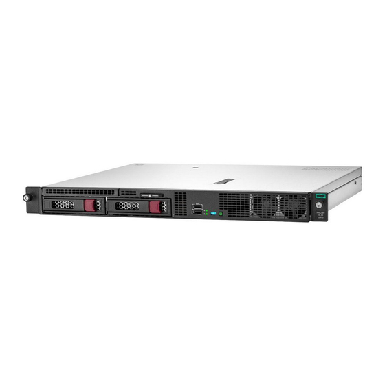
Servidor HPE ProLiant DL20
Geração 10
O servidor HPE ProLiant DL20 Gen10 entrega um servidor
compacto e versátil por um preço acessível. Implante o
formato portátil em escritórios pequenos, remotos e filiais
como uma plataforma de ponto de venda compacta,
porém poderosa, em ambientes de transporte, varejo e
hotelaria, ou como uma configuração flexível para
personalização em ambientes com restrição de espaço de
clientes OEM, militares ou governamentais.
www.bztech.com.br
Advertisement
Table of Contents

Related Manuals for HPE ProLiant DL20 Gen10


Summary of Contents for HPE ProLiant DL20 Gen10
- Page 1 Servidor HPE ProLiant DL20 Geração 10 O servidor HPE ProLiant DL20 Gen10 entrega um servidor compacto e versátil por um preço acessível. Implante o formato portátil em escritórios pequenos, remotos e filiais como uma plataforma de ponto de venda compacta, porém poderosa, em ambientes de transporte, varejo e...
- Page 2 HPE ProLiant DL20 Gen10 Server User Guide Abstract This document is for the person who installs, administers, and troubleshoots servers and storage systems. Hewlett Packard Enterprise assumes you are qualified in the servicing of computer equipment and trained in recognizing hazards in products with hazardous energy levels.
- Page 3 Notices The information contained herein is subject to change without notice. The only warranties for Hewlett Packard Enterprise products and services are set forth in the express warranty statements accompanying such products and services. Nothing herein should be construed as constituting an additional warranty. Hewlett Packard Enterprise shall not be liable for technical or editorial errors or omissions contained herein.
-
Page 4: Table Of Contents
Contents Component identification................7 Front panel components........................7 Serial number/iLO information pull tab..................9 Front panel LEDs and buttons......................9 UID button functionality......................10 Front panel LED power fault codes..................10 Rear panel components........................11 Rear panel LEDs..........................12 System board components........................13 System maintenance switch descriptions................15 DIMM slot locations........................ - Page 5 Installing the Chassis Intrusion Detection switch..............88 HPE Trusted Platform Module 2.0 Gen10 option................89 Overview..........................89 HPE Trusted Platform Module 2.0 Guidelines................ 90 Installing and enabling the HPE TPM 2.0 Gen10 Kit.............. 90 Installing the Trusted Platform Module board.............. 90 Enabling the Trusted Platform Module.................93...
- Page 6 Scripting Toolkit for Windows and Linux..................112 UEFI System Utilities........................112 Selecting the boot mode ...................... 112 Secure Boot.......................... 113 Launching the Embedded UEFI Shell ..................114 HPE Smart Storage Administrator....................114 USB support............................ 115 External USB functionality....................115 Redundant ROM support.........................115 Safety and security benefits....................115 Keeping the system current......................
- Page 7 Mechanical specifications........................123 Power supply specifications......................123 ATX 290W Non-Hot-plug Power Supply................123 HPE 500W Flex Slot Platinum Hot-plug Low Halogen Power Supply........124 HPE 800W Flex Slot -48VDC Hot plug Low Halogen Power Supply........124 Safety, warranty, and regulatory information........126 Regulatory information........................126 Local representative information...................126...
-
Page 8: Component Identification
Component identification This chapter describes the external and internal server features and components. Front panel components Two-bay LFF non-hot-plug drive model Item Description Optical drive (optional) Serial number/iLO information pull tab iLO Service Port USB 3.0 port Two-bay LFF non-hot-plug drive cage Two-bay LFF hot-plug drive model Component identification... - Page 9 Item Description Optical drive (optional) Serial number/iLO information pull tab iLO Service Port USB 3.0 port Two-bay LFF hot-plug drive bays Four-bay SFF hot-plug drive model Item Description Media drive bay Serial number/iLO information pull tab iLO Service Port USB 3.0 port Four-bay SFF hot-plug drive bays The media drive bay supports an optical drive assembly or a two-bay SFF drive cage assembly.
-
Page 10: Serial Number/Ilo Information Pull Tab
The other side shows the default iLO account information and QR code label. Use a mobile device to scan the QR code label to display the server mobile product page (http:// www.hpe.com/qref/dl20gen10). This page contains links to server setup information, spare part numbers, QuickSpecs, troubleshooting resources, and other useful product links. -
Page 11: Uid Button Functionality
UID button functionality The UID button can be used to display the Server Health Summary when the server will not power on. For more information, see the iLO user guide on the Hewlett Packard Enterprise website (http://www.hpe.com/ support/ilo-docs). Front panel LED power fault codes The following table provides a list of power fault codes, and the subsystems that are affected. -
Page 12: Rear Panel Components
LED behavior Memory 3 flashes Riser board PCIe slots 4 flashes FlexibleLOM 5 flashes Removable HPE Smart Array SR Gen10 controller 6 flashes System board PCIe slots 7 flashes Power backplane or storage backplane 8 flashes Power supply 9 flashes... -
Page 13: Rear Panel Leds
If FlexibleLOM is installed in the server, the shared iLO port behavior will be default to port 1 of the FlexibleLOM card. Rear panel LEDs Item Status Definition Solid blue Activated Flashing blue • 1 flash per second = Remote management of firmware upgrade in progress •... -
Page 14: System Board Components
Item Status Definition Flashing green Network active No network activity NIC link Solid green Network link No network link iLO status Solid green Link to network Flashing green Network active No network activity iLO link Solid green Network link No network link System board components Component identification... - Page 15 Item Description PCIe riser connector System maintenance switch Onboard M.2/Dedicated iLO management connector Storage backup power connector for slot 1 Fan connector 2 Fan connector 1 System battery Chassis Intrusion Detection switch Standard or Flexible Slot power supply connector Two-bay SFF drive sideband connector Smart Storage Battery connector Standard or Flexible Slot power supply sideband connector Flexible slot power supply connector...
-
Page 16: System Maintenance Switch Descriptions
System maintenance switch descriptions Position Default Function Off = iLO 5 security is enabled. On = iLO 5 security is disabled. Reserved Reserved Reserved Off = Power-on password is enabled. On = Power-on password is disabled. Off = No function On = Restore default manufacturing settings Reserved —... -
Page 17: Dimm Label Identification
DIMM label identification To determine DIMM characteristics, see the label attached to the DIMM. The information in this section helps you to use the label to locate specific information about the DIMM. Item Description Example Capacity 8 GB 16 GB 32 GB 64 GB 128 GB... -
Page 18: Pcie Riser Board Slot Definitions
L = LRDIMM (load reduced) E = Unbuffered ECC (UDIMM) For more information about product features, specifications, options, configurations, and compatibility, see the product QuickSpecs on the Hewlett Packard Enterprise website (http://www.hpe.com/info/qs). PCIe riser board slot definitions • FlexibleLOM riser board... -
Page 19: Drive Led Definitions
Item Slot number Form factor Slot description Low-profile PCIe3 x8 (8,4,1) Full-height, half-length PCIe3 x16 (8,4,1) Drive LED definitions Low profile LFF drive LED definitions Item Status Definition Fault Solid amber The drive has failed. \Locate Solid blue The drive is operating normally and being identified by a management application. -
Page 20: Hot-Plug Drive Led Definitions
Item Status Definition Flashing green The drive is doing one of the following: • Rebuilding (1 flash per second) • Performing a RAID migration • Performing a strip size migration • Performing a capacity expansion • Performing a logical drive extension •... -
Page 21: Drive Bay Numbering
Item LED Status Definition The drive is doing one of the following: Flashing green • Rebuilding • Performing a RAID migration • Performing a strip size migration • Performing a capacity expansion • Performing a logical drive extension • Erasing •... - Page 22 • Four-bay SFF hot-plug drive model • Six-bay SFF hot-plug drive model Component identification...
-
Page 23: Fan Locations
Fan locations Component identification... -
Page 24: Setup
Delivered by experienced, certified engineers, Hewlett Packard Enterprise support services help you keep your servers up and running with support packages tailored specifically for HPE ProLiant systems. Hewlett Packard Enterprise support services let you integrate both hardware and software support into a single package. - Page 25 • Obtain the storage driver if needed: ◦ Download it from the HPE Support Center website: http://www.hpe.com/support/hpesc ◦ Extract it from the SPP. • Read the rack warnings and cautions: Rack warnings and cautions on page 28 • Read the server warnings and cautions:...
- Page 26 From the boot screen, press F9 to run UEFI System Utilities. From the UEFI System Utilities screen, select System Configuration > Embedded Storage: HPE Smart Storage S100i SR Gen10 > Array Configuration > Create Array. Deploy an OS or virtualization software 8.
-
Page 27: Operational Requirements
Press F11 at boot screen to select the boot device. c. After the OS installed, update the drivers. Register the server 9. To experience quicker service and more efficient support, register the server at the HPE website: https://myenterpriselicense.hpe.com Operational requirements... -
Page 28: Temperature Requirements
CAUTION: If a third-party rack is used, observe the following additional requirements to ensure adequate airflow and to prevent damage to the equipment: • Front and rear doors—If the 42U rack includes closing front and rear doors, you must allow 5,350 sq cm (830 sq in) of holes evenly distributed from top to bottom to permit adequate airflow (equivalent to the required 64 percent open area for ventilation). -
Page 29: Server Warnings And Cautions
locking-style plugs or those complying with IEC 60309 are considered suitable for this purpose. Using common power outlet strips for the server is not recommended. Server warnings and cautions WARNING: To reduce the risk of personal injury, electric shock, or damage to the equipment, disconnect the power cord to remove power from the server. -
Page 30: Electrostatic Discharge
WARNING: The chassis is heavy. To reduce the risk of personal injury or damage to the equipment, do the following: • Observe local occupational health and safety requirements and guidelines for manual material handling. • Get help to lift and stabilize the product during installation or removal, especially when the product is not fastened to the rails. -
Page 31: Configuring The Server
For more information on these requirements, see the HPE UEFI Requirements on the Hewlett Packard Enterprise website. To install an operating system on the server, use one of the following methods: •... -
Page 32: Installing The Operating System With Intelligent Provisioning
For additional system software and firmware updates, download the Service Pack for ProLiant from the Hewlett Packard Enterprise website. Software and firmware must be updated before using the server for the first time, unless any installed software or components require an older version. For more information, see Keeping the system current on page 115. -
Page 33: Operations
Operations Removing the security bezel (optional) Procedure 1. Press the latch. 2. Open the security bezel. 3. Detach the security bezel from the chassis ear. Installing the security bezel (optional) Procedure 1. Attach the security bezel to the latch ear. 2. -
Page 34: Powering Down The Server
4. Install the Kensington security lock. For more information about the Kensington security lock, see the document with the component. Powering down the server Before powering down the server for any upgrade or maintenance procedures, perform a backup of critical server data and programs. -
Page 35: Extending The Server From The Rack
Extending the server from the rack WARNING: To reduce the risk of personal injury or equipment damage, be sure that the rack is adequately stabilized before extending a component from the rack. Prerequisites Before you perform this procedure, make sure that you have T-25 screwdriver available. Procedure 1. -
Page 36: Removing The Server From The Rack
c. Slide the server out of the rack. 6. Extend the server on the rack rails until the server rail-release latches are engaged. Removing the server from the rack WARNING: This server is heavy. To reduce the risk of personal injury or damage to the equipment: •... -
Page 37: Removing The Access Panel
7. Place the server on a sturdy, level surface. Removing the access panel WARNING: To reduce the risk of personal injury from hot surfaces, allow the drives and the internal system components to cool before touching them. CAUTION: To prevent damage to electrical components, take the appropriate anti-static precautions before beginning any installation, removal, or replacement procedure. -
Page 38: Installing The Access Panel
• Extend the server from the rack. • Remove the server from the rack. 5. Remove the access panel: a. If the locking latch is locked, use a T-15 Torx screwdriver to unlock the latch. b. Press the release button and pull up the latch to disengage the access panel from the chassis. c. -
Page 39: Removing The Riser Cage
Removing the riser cage WARNING: To reduce the risk of personal injury from hot surfaces, allow the drives and the internal system components to cool before touching them. CAUTION: To prevent damage to the server or expansion boards, power down the server, and disconnect all power cords before removing or installing the riser cage. -
Page 40: Installing The Riser Cage
Installing the riser cage CAUTION: To prevent damage to the server or expansion boards, power down the server, and disconnect all power cords before removing or installing the riser cage. Procedure 1. Connect all necessary internal cabling to the expansion board. 2. -
Page 41: Installing The Server Into The Rack
Installing the server into the rack Prerequisites Before you perform this procedure, make sure you have the T-25 Torx screwdriver available. Procedure Install the rack rail option. Do the following: a. Align the mounting rail of the server with the rack rail. b. - Page 42 • For server with latch ears, if necessary, open the latches and tighten the screws. Connect peripheral devices to the server. For information on identifying connectors, see Rear panel components on page 11. Connect the power cord to the power supply. For hot-plug power supply: To prevent accidental power cord disconnection when sliding the server in and out of the rack, secure the power cord in the strain relief strap attached to the power input module handle:...
- Page 43 For non-hot-plug power supply: To prevent the accidental disconnection of the power cord when sliding the server into and from the rack, secure the power cord through the strain relief clip: a. If the clip is positioned too near the power cord that it blocks the power cord plug connection, pull the release tab and then slide the clip backward.
- Page 44 e. Slide the clip forward until it is flush against the edge of the power cord plug. To secure the power cords and other rear panel cables to the rack rail, use the hook-and-loop strap. For detailed instructions, see Installing the rack rail hook-and-loop strap on page 48. Connect the power cord to the power source.
-
Page 45: Hardware Options Installation
Hardware options installation This chapter provides detailed instructions on how to install hardware options. For more information on supported options, see the product QuickSpecs on the HPE ProLiant DL20 Gen10 Server website at: http://www.hpe.com/servers/dl20-gen10 To view the warranty for your server and supported options, see Warranty information on page 128. - Page 46 2. Install the sliding rails on the server tray. 3. Remove the pins and also the pin nuts from the ends of the right and left rails. Hardware options installation...
- Page 47 4. Fasten the mounting rails to the rack columns: • For square hole racks: align the rail pins with the holes of the rack column and insert the pins. • For round hole racks: align the rail pins with the holes of the rack column and mount the rails by fastening the screws.
- Page 48 5. Slide the server tray into the rack. The rails will click and lick into place when the tray is properly engaged. Hardware options installation...
-
Page 49: Installing The Rack Rail Hook-And-Loop Strap
Installing the rack rail hook-and-loop strap The rack rail hook-and-loop strap can be installed on either the left or right rack rail. Hewlett Packard Enterprise recommends installing it on the left rack rail for better cable management. To install the rack rail hook-and-loop strap: 1. -
Page 50: Drive Options
Drive options Drive installation guidelines Observe the following general guidelines: • The system automatically sets all drive numbers. • If only one drive is used, install it in the bay with the lowest drive number. For drive numbering, see Drive bay numbering on page 20. •... - Page 51 Procedure If installed, remove the security bezel. Power down the server. Remove all power: a. Disconnect each power cord from the power source. b. Disconnect each power cord from the server. Do one of the following: • Extend the server from the rack. •...
- Page 52 Install the drive. 10. Install the non-hot-plug drive cage assembly. Hardware options installation...
-
Page 53: Installing An Lff Hot-Plug Drive
16. Power up the server. 17. If removed, install the security bezel. The installation is complete. To configure arrays, see the HPE Smart Array SR Gen10 Configuration Guide at the Hewlett Packard Enterprise website. Installing an LFF hot-plug drive CAUTION: To prevent improper cooling and thermal damage, do not operate the server unless all bays are populated with either a component or a blank. -
Page 54: Installing An Sff Hot-Plug Drive
4. Install the drive. 5. Determine the status of the drive from the drive LED definitions. The installation is complete. To configure arrays, see the HPE Smart Array SR Gen10 Configuration Guide at the Hewlett Packard Enterprise website. Installing an SFF hot-plug drive CAUTION: To prevent improper cooling and thermal damage, do not operate the server unless all bays are populated with either a component or a blank. -
Page 55: Power Supply Options
4. Install the SFF drive. 5. Determine the status of the drive from the drive LED definitions. The installation is complete. To configure arrays, see the HPE Smart Array SR Gen10 Configuration Guide at the Hewlett Packard Enterprise website. Power supply options Depending on the installed options and the regional location where the server was purchased, the server can be configured with one of the following power supplies. -
Page 56: Power Supply Warnings And Cautions
Power supply warnings and cautions WARNING: To reduce the risk of electric shock or damage to the equipment: • Do not disable the power cord grounding plug. The grounding plug is an important safety feature. • Plug the power cord into a grounded (earthed) electrical outlet that is easily accessible at all times. •... -
Page 57: Optical Drive Enablement Option
2. Slide the power supply into the bay until it clicks into place. 3. Connect the power cord to the power supply. 4. Secure the power cord in the strain relief strap attached to the power supply handle. 5. Connect the power cord to the power source. 6. - Page 58 • Optical drive enablement kit • T-10 Torx screwdriver • Phillips screwdriver Procedure If installed, remove the security bezel. Power down the server. Remove all power: a. Disconnect each power cord from the power source. b. Disconnect each power cord from the server. Do one of the following: •...
- Page 59 Install the optical drive cage assembly in the server. Connect the SATA-power Y-cable. 10. Install the access panel. 11. Install the server into the rack. 12. Connect each power cord to the server. 13. Connect each power cord to the power source. 14.
-
Page 60: Installing The Optical Drive Enablement Option For Sff Configuration
Installing the optical drive enablement option for SFF configuration Prerequisites Before you perform this procedure, make sure that you have the following items available: • Optical drive enablement kit • T-10 Torx screwdriver • Phillips screwdriver Procedure If installed, remove the security bezel. Power down the server. - Page 61 Install the optical drive bracket. Install the optical drive in the optical drive cage. Hardware options installation...
-
Page 62: Two-Bay Sff Hot-Plug Drive Enablement Option
10. Install the optical drive cage assembly in the server: 11. Connect the SATA-power Y-cable. 12. Install the access panel. 13. Install the server into the rack. 14. Connect each power cord to the server. 15. Connect each power cord to the power source. 16. -
Page 63: Installing The Two-Bay Sff Hot-Plug Drive Enablement Drive Cage
Installing the two-bay SFF hot-plug drive enablement drive cage Prerequisites Before you perform this procedure, make sure that you have the following items available: • Two-bay SFF drive enablement kit • Two SFF drives • T-10 screwdriver Procedure If installed, remove the security bezel. Power down the server. -
Page 64: Memory Options
BIOS initialization. All memory installed in the server must be of the same type. DIMM population information For specific DIMM population information, see the DIMM population guidelines on the Hewlett Packard Enterprise website (http://www.hpe.com/docs/standard-population-rules). Installing a DIMM Procedure If installed, remove the security bezel. -
Page 65: Expansion Board Options
a. Disconnect each power cord from the power source. b. Disconnect each power cord from the server. Do one of the following: • Extend the server from the rack. • Remove the server from the rack. Remove the access panel. Open the DIMM slot latches. -
Page 66: Installing An Expansion Board
Installing an expansion board Prerequisites Before you perform this procedure, make sure that you have the following items available: • Expansion board option kit • External and internal cabling required by the expansion board • T-10 Torx screwdriver Procedure If installed, remove the security bezel. Power down the server. - Page 67 Retain the screw for future use. Install the expansion board. • Slot 1 • Slot 2 Hardware options installation...
-
Page 68: Installing The M.2 Sata Ssd Expansion Board And M.2 Sata Cables
10. Install the PCIe riser cage. 11. Connect all necessary internal cabling to the expansion board. For more information on the cabling requirements, see the documentation that ships with the option. 12. Install the access panel. 13. Install the server into the rack. 14. - Page 69 If installing the expansion board into slot 1 of the PCIe riser cage, do the following: a. Remove the full-height bracket from the M.2 SATA SSD expansion board. b. Install the low-profile bracket onto the expansion board. Install the M.2 SATA SSD module on the expansion board: a.
-
Page 70: Storage Controller Options
10. Install the M.2 SATA SSD expansion board. 11. Install the PCIe riser cage. 12. Connect the M.2 SATA cables. 13. Install the access panel. 14. Install the server into the rack. 15. Connect each power cord to the server. 16. - Page 71 CAUTION: In systems that use external data storage, be sure that the server is the first unit to be powered down and the last to be powered back up. Taking this precaution ensures that the system does not erroneously mark the drives as failed when the server is powered up. Procedure If installed, remove the security bezel.
-
Page 72: External Type-P And Type-E Smart Array Sr Gen10 Controller Option
14. Power up the server. 15. If removed, install the security bezel. The installation is complete. To configure arrays, see the HPE Smart Array SR Gen10 Configuration Guide at the Hewlett Packard Enterprise website. External type-P and type-E Smart Array SR Gen10 controller option The server supports the following external controllers: •... -
Page 73: M.2/Dedicated Ilo/Serial Port Option
Connect the cable. When routing the Smart Storage Battery cable, make sure that it does not block the air flow of the fan and route the cable under the metal tab. Install the access panel. Install the server into the rack. 10. -
Page 74: M.2/Dedicated Ilo/Serial Port Option Kit Content
M.2 2280 SSD standoff position M.2 2242 SSD standoff position M.2 SSD module connector Serial port cable Serial port cable clip NOTE: Enablement board stabilizer and serial port cable clip are not used in HPE ProLiant DL20 Gen10 server. Hardware options installation... -
Page 75: M.2 Ssd System Board Connectors
M.2 SSD system board connectors Item Description Standoff position to secure the 22110 M.2 SSD module Standoff position to secure the 2280 M.2 SSD module Standoff position to secure the 2242 M.2 SSD module M.2 SSD module connector Installing the M.2/dedicated iLO/serial port enablement board Prerequisites Before you perform this procedure, make sure that you have the following items available: •... - Page 76 • Extend the server from the rack. • Remove the server from the rack. Remove the access panel. Remove the PCIe riser cage. Remove the iLO port blank. Remove the M.2 air guider. Remove the screw and the standoff. Hardware options installation...
- Page 77 10. Smoothen the tape mylar on the system board. 11. Install the M.2/ dedicated iLO/serial port enablement board: a. Insert the enablement board in the slot. b. Press down the other end of the board. c. Secure the board with screw. Hardware options installation...
- Page 78 12. Identify the standoff position on the enablement board for securing the M.2 NVMe SSD and install the standoff. 13. If you intend to install the M.2 SSD, install it now. 14. Install the serial port 15. Install the PCIe riser cage. 16.
-
Page 79: M.2 Ssd Module Option
M.2 SSD on the server. Installing the M.2 SSD on the system board IMPORTANT: When installing HPE 400GB NVMe x4 MU M.2 22110 DS SSD (875583-B21) and HPE 480GB NVMe x4 RI M.2 22110 DS SSD (875579-001) modules, the supporting ambient temperature should be under 30°C (86°F). - Page 80 Identify the standoff position on the system board for securing the M.2 NVMe SSD. Remove the alignment screws: • If installing an M.2 2242 or 2280 SSD, remove both the standoff (Hex nut) screw and Phillips screw. • If installing the M.2 22110, remove only the Phillips screw. Retain the standoff (Hex nut) screw. Hardware options installation...
- Page 81 Install the standoff (hex nut) screw on 2242 or 2280 standoff position on the system board. 10. Install the M.2 SSD module: a. Insert the SSD into the M.2 slot at a 45° angle. b. Carefully press the SSD down to the horizontal position. c.
-
Page 82: Installing An M.2 Ssd Module On M.2/Dedicated Ilo/Serial Port Enablement Board
17. If removed, install the security bezel. The installation is complete. To configure the M.2 SSD, see the HPE Smart Array SR Gen10 Configuration Guide at the Hewlett Packard Enterprise website. Installing an M.2 SSD module on M.2/dedicated iLO/serial port enablement board... - Page 83 14. Connect each power cord to the power source. 15. Power up the server. 16. If removed, install the security bezel. The installation is complete. To configure the M.2 SSD, see the HPE Smart Array SR Gen10 Configuration Guide at the Hewlett Packard Enterprise website. Hardware options installation...
-
Page 84: Installing The Serial Port
Installing the Serial Port Prerequisites Before you perform this procedure, make sure that you have the following items available: • T-15 Torx screwdriver • Sleeve screwdriver Procedure If installed, remove the security bezel. Power down the server. Remove all power: a. -
Page 85: Enabling The Dedicated Ilo Management Module
The onboard NIC 1/shared iLO connector is set as the default system iLO connector. To enable the dedicated iLO management module, use the iLO 5 Configuration Utility accessible within the HPE UEFI System Utilities. For more information on the UEFI System Utilities, see the UEFI documentation on the Hewlett Packard Enterprise website (http://www.hpe.com/servers/uefi). -
Page 86: Flexiblelom Riser Option
3. Select Network Options, and then press Enter. The Network Options screen appears. 4. Set the Network Interface Adapter field to ON, and then press Enter. 5. Press F10 to save your changes. A message prompt to confirm that the iLO settings reset appears. 6. -
Page 87: Transceiver Option
Install the component: a. Firmly seat the FlexibleLOM riser into the slot. b. Secure the FlexibleLOM riser with a screw. Install the FLOM riser cage. 10. Install the access panel. 11. Install the server into the rack. 12. Connect all necessary external cabling. 13. -
Page 88: Installing A Transceiver
CAUTION: The presence of dust in transceiver ports can cause poor cable connectivity. To prevent dust from entering, install a dust plug in an unused transceiver port. CAUTION: Supported transceivers can be hot-swapped—removed and installed while the server is powered-on. However, to prevent potential damage to the transceiver or the fiber-optic cable, disconnect the cable from the transceiver before hot-swapping it. -
Page 89: Chassis Intrusion Detection Option
4. Connect a compatible network cable to the transceiver. 5. If needed, see the transceiver documentation for the model-specific fastening mechanism applicable to the transceiver. The installation is complete. Chassis Intrusion detection option The chassis intrusion detection option detects if the chassis access cover is opened or closed. The iLO management processor monitors the switch and if there is a change (if the access cover is either opened or closed), it creates a log entry noting the intrusion. -
Page 90: Hpe Trusted Platform Module 2.0 Gen10 Option
HPE Trusted Platform Module 2.0 Gen10 option Overview Use these instructions to install and enable an HPE TPM 2.0 Gen10 Kit in a supported server. This option is not supported on Gen9 and earlier servers. This procedure includes three sections: 1. -
Page 91: Hpe Trusted Platform Module 2.0 Guidelines
IMPORTANT: In UEFI Boot Mode, the HPE TPM 2.0 Gen10 Kit can be configured to operate as TPM 2.0 (default) or TPM 1.2 on a supported server. In Legacy Boot Mode, the configuration can be changed between TPM 1.2 and TPM 2.0, but only TPM 1.2 operation is supported. - Page 92 WARNING: The front panel Power On/Standby button does not shut off system power. Portions of the power supply and some internal circuitry remain active until AC power is removed. To reduce the risk of personal injury, electric shock, or damage to the equipment, remove power from the server: For rack and tower servers, remove the power cord.
- Page 93 3. Install the TPM cover: a. Line up the tabs on the cover with the openings on either side of the TPM connector. b. To snap the cover into place, firmly press straight down on the middle of the cover. 4.
-
Page 94: Enabling The Trusted Platform Module
5. Connect each power cord to the power source. 6. Power up the server. 7. If removed, install the security bezel. Enabling the Trusted Platform Module When enabling the Trusted Platform module, observe the following guidelines: • By default, the Trusted Platform Module is enabled as TPM 2.0 when the server is powered on after installing it. -
Page 95: Retaining The Recovery Key/Password
For more information, see the Microsoft website. Enabling the Trusted Platform Module as TPM 1.2 Procedure 1. During the server startup sequence, press the F9 key to access System Utilities. 2. From the System Utilities screen select System Configuration > BIOS/Platform Configuration (RBSU) >... -
Page 96: Cabling
Cabling Cabling guidelines The cable colors in the cabling diagrams used in this chapter are for illustration purposes only. Most of the server cables are black. Observe the following guidelines when working with server cables. Before connecting cables • Note the port labels on the PCA components. Not all of these components are used by all servers: ◦... -
Page 97: Storage Cabling
• Remove cables that are no longer being used. Retaining them inside the server can restrict airflow. If you intend to use the removed cables later, label and store them for future use. Storage cabling Non-hot-plug drive cabling Two-bay LFF non-hot-plug drive embedded controller cabling Cable color Description Orange... -
Page 98: Hot-Plug Drive Cabling
Two-bay LFF non-hot-plug drive Smart Array modular controller (AROC) cabling Cable color Description Orange Mini-SAS cable from drive backplane to modular controller (AROC) port 1 Blue Drive backplane power cable Hot-plug drive cabling Two-bay LFF hot-plug drive cabling Two-bay LFF hot-plug drive embedded controller cabling Cable color Description Orange... -
Page 99: Four Bay Sff Hot-Plug Drive Cabling
Two-bay LFF hot-plug drive Smart Array modular controller (AROC) cabling Cable color Description Blue Drive backplane power cable Orange Min-SAS cable from drive backplane to AROC port 1 Four bay SFF hot-plug drive cabling Four-bay SFF hot-plug drive embedded controller cabling Cable color Description Orange... -
Page 100: 4+2 Bay Sff Hot-Plug Drive Cabling
4+2 bay SFF hot-plug drive cabling 4+2 bay SFF hot-plug drive embedded controller cabling Cable color Description Orange Four-bay SFF drive backplane power cable Blue Mini-SAS cable Gold Two-bay SFF to four-bay SFF drive backplane power cable Pink SATA cable and drive sideband cable 4+2 bay SFF hot-plug drive Smart Array modular controller (AROC) cabling Cabling... -
Page 101: M.2 Sata Ssd Cabling
Cable color Description Blue Mini-SAS cable from two-bay SFF drive backplane to AROC port 2 Orange Mini-SAS cable from four-bay SFF drive backplane Mini-SAS cable to AROC port 1 Gold Four-bay SFF drive backplane power cable Pink Two-bay to four-bay SFF drive backplane power cable M.2 SATA SSD cabling M.2 SATA SSD in slot 1 Cable color... -
Page 102: Smart Storage Battery Cabling
M.2 SATA SSD in slot 2 Cable color Description Orange SATA cable to x1 SATA port 2 Blue SATA cable to x1 SATA port 1 Smart Storage Battery cabling Cabling... -
Page 103: Storage Controller Backup Power Cabling
Storage controller backup power cabling Smart Array P-class storage controller in slot 1 Cable color Description Orange Slot 1 storage controller backup power cable Smart Array P-class storage controller in slot 2 Cable color Description Orange Slot 2 storage controller backup power cable Cabling... -
Page 104: Optical Drive Cabling
Optical drive cabling LFF configuration Cable color Description Orange SATA-power Y-cable to x1 SATA port 2 Blue Power extension cable SFF configuration Cable color Description Orange SATA-power-Y cable to x1 SATA port 2 Blue Power extension cable Cabling... -
Page 105: Fan Cabling
Fan cabling Cable color Description Orange Fan 1 cable Blue Fan 2 cable Gold Fan 3 cable Chassis Intrusion detection cabling Cabling... -
Page 106: M.2/Dedicated Ilo/Serial Port Cabling
M.2/dedicated iLO/serial port cabling Power supply cabling • Non-hot-plug Cable color Description Orange 16-pin power supply sideband cable Blue 14-pin power supply cable • Hot-plug Cabling... - Page 107 Cable color Description Orange 14-pin power supply cable Blue Redundant power supply sideband cable Cabling...
-
Page 108: Software And Configuration Utilities
Product QuickSpecs For more information about product features, specifications, options, configurations, and compatibility, see the product QuickSpecs on the Hewlett Packard Enterprise website (http://www.hpe.com/info/qs). Active Health System Viewer Active Health System Viewer (AHSV) is an online tool used to read, diagnose, and resolve server issues quickly using AHS uploaded data. -
Page 109: Active Health System Data Collection
HPE iLO 5 iLO 5 is a remote server management processor embedded on the system boards of HPE ProLiant servers and Synergy compute modules. iLO enables the monitoring and controlling of servers from remote locations. -
Page 110: Ilo Federation
For more information about iLO Federation, see the iLO user guide at the following website: http:// www.hpe.com/support/ilo-docs. iLO Service Port When you have physical access to a server, you can use the Service Port to do the following: Download the Active Health System Log to a supported USB flash drive. -
Page 111: Ilo Restful Api
RESTful Interface Tool The RESTful Interface Tool (iLOREST) is a scripting tool that allows you to automate HPE server management tasks. It provides a set of simplified commands that take advantage of the iLO RESTful API. You can install the tool on your computer for remote use or install it locally on a server with a Windows or Linux Operating System. -
Page 112: Intelligent Provisioning Operation
Management Security HPE ProLiant Gen10 servers are built with some of the industry's most advanced security capabilities, out of the box, with a foundation of secure embedded management applications and firmware. The management security provided by HPE embedded management products enables secure support of modern workloads,... -
Page 113: Scripting Toolkit For Windows And Linux
Advanced and iLO Advanced Premium Security Edition licenses provides security features that help ensure protection, detection, and recovery from advanced cyber-attacks. For more information, see the HPE Gen10 Server Security Reference Guide on the Hewlett Packard Enterprise Information Library at http://www.hpe.com/support/gen10- security-ref-en. -
Page 114: Secure Boot
Operating systems must support Secure Boot and have an EFI boot loader signed with one of the authorized keys to boot. For more information about supported operating systems, see http:// www.hpe.com/servers/ossupport. You can customize the certificates embedded in the UEFI BIOS by adding or removing your own certificates, either from a management console directly attached to the server, or by remotely connecting to the server using the iLO Remote Console. -
Page 115: Launching The Embedded Uefi Shell
HPE Smart Storage Administrator HPE SSA is the main tool for configuring arrays on HPE Smart Array SR controllers. It exists in three interface formats: the HPE SSA GUI, the HPE SSA CLI, and HPE SSA Scripting. All formats provide support for configuration tasks. -
Page 116: Usb Support
Array controllers and integrated Smart Array controllers. Some HPE SSA features are only available in the offline environment, such as setting the boot controller and boot volume. • Accessing HPE SSA in the online environment This method requires an administrator to download the HPE SSA executables and install them. You can run HPE SSA online after launching the host operating system. -
Page 117: Service Pack For Proliant
NOTE: SUM does not support third-party controllers, including flashing hard drives behind the controllers. Integrated Smart Update Tools Integrated Smart Update Tools (iSUT) is a software utility used with iLO 4, iLO 5, iLO Amplifier Pack, HPE OneView, Service Pack for ProLiant (SPP), and Smart Update Manager (SUM) to stage, install, and activate firmware and driver updates. -
Page 118: Updating Firmware From The System Utilities
HPE OneView: Displays available updates for servers. Communicates with iSUT (or SUT 1.x) to initiate updates, reports the status on the Firmware section of the Server Profile page of HPE OneView. HPE OneView provides automated compliance reporting in the dashboard. -
Page 119: Updating The Firmware From The Uefi Embedded Shell
Procedure 1. Access the System ROM Flash Binary component for your server from the Hewlett Packard Enterprise Support Center (http://www.hpe.com/support/hpesc). 2. Copy the binary file to a USB media or iLO virtual media. 3. Attach the media to the server. -
Page 120: Operating System Version Support
HPE Pointnext Portfolio HPE Pointnext delivers confidence, reduces risk, and helps customers realize agility and stability. Hewlett Packard Enterprise helps customers succeed through Hybrid IT by simplifying and enriching the on-premise experience, informed by public cloud qualities and attributes. -
Page 121: Troubleshooting
• Error Message Guide for HPE ProLiant Gen10 servers and HPE Synergy provides a list of error messages and information to assist with interpreting and resolving error messages. •... -
Page 122: System Battery Replacement
System battery replacement Removing and replacing the system battery Prerequisites Before you perform this procedure make sure that you have flat-headed, nonconductive tool. Procedure 1. If installed, remove the security bezel. 2. Power down the server. 3. Remove all power: a. -
Page 123: Specifications
Specifications Environmental specifications Specifications Value Temperature range* — Operating 10°C to 35°C (50°F to 95°F) Nonoperating -30°C to 60°C (-22°F to 140°F) Relative humidity — (noncondensing) Operating 8% to 90% 28°C (82.4°F) maximum wet bulb temperature Nonoperating 5 to 95% 38.7°C (101.7°F) maximum wet bulb temperature Altitude —... -
Page 124: Mechanical Specifications
• ATX 290W Non-hot-plug Power Supply • HPE 500W Flex Slot Platinum Hot-plug Low Halogen Power Supply • HPE 800W Flex Slot -48VDC Hot-plug Low Halogen Power Supply These are entry class power supply products for ProLiant Servers. For detailed power supply specifications, see the QuickSpecs on the Hewlett Packard Enterprise website. -
Page 125: Hpe 500W Flex Slot Platinum Hot-Plug Low Halogen Power Supply
500 W at 100 VAC to 127 VAC input 500 W at 100 VAC to 240 VAC input 500 W at 240 VDC input for China only HPE 800W Flex Slot -48VDC Hot plug Low Halogen Power Supply Specification Value Input requirements —... - Page 126 Specification Value Power supply output — Rated steady-state power (W) 800 W at -40 VDC to -72 VDC Maximum peak power (W) 800 W at -40 VDC to -72 VDC Maximum peak power 800 W at 200 VAC to 277 VAC 800 W at -40VDC to -72 VDC WARNING: To reduce the risk of electric shock or energy hazards: •...
-
Page 127: Safety, Warranty, And Regulatory Information
To view the regulatory information for your product, view the Safety and Compliance Information for Server, Storage, Power, Networking, and Rack Products, available at the Hewlett Packard Enterprise Support Center: www.hpe.com/support/Safety-Compliance-EnterpriseProducts Additional regulatory information Hewlett Packard Enterprise is committed to providing our customers with information about the chemical substances in our products as needed to comply with legal requirements such as REACH (Regulation EC No 1907/2006 of the European Parliament and the Council). -
Page 128: Turkey Rohs Material Content Declaration
Belarus: Kazakhstan: Turkey RoHS material content declaration Ukraine RoHS material content declaration GS Gloss declaration The product is not suitable for use at visual display workplaces according to §2 of the German Ordinance for Work with Visual Display Units. Das Produkt ist nicht für den Einsatz an Bildschirmarbeitsplätzen im Sinne § 2 der Bildschirmarbeitsverordnung geeignet. -
Page 129: Websites
For additional general support websites, see Support and other resources. Product websites Product QuickSpecs http://www.hpe.com/servers/dl20-gen10 HPE ProLiant DL20 Gen10 support page http://www.hpe.com/support/dl20gen10 HPE ProLiant DL20 Gen10 user documents http://www.hpe.com/info/dl20gen10-docs Warranty information To view the warranty for your product or to view the Safety and Compliance Information for Server, Storage,... -
Page 130: Support And Other Resources
Support and other resources Accessing Hewlett Packard Enterprise Support • For live assistance, go to the Contact Hewlett Packard Enterprise Worldwide website: http://www.hpe.com/assistance • To access documentation and support services, go to the Hewlett Packard Enterprise Support Center website: http://www.hpe.com/support/hpesc Information to collect •... -
Page 131: Customer Self Repair
Hewlett Packard Enterprise Support Center More Information on Access to Support Materials page: www.hpe.com/support/AccessToSupportMaterials IMPORTANT: Access to some updates might require product entitlement when accessed through the Hewlett Packard Enterprise Support Center. You must have an HPE Passport set up with relevant entitlements. Customer self repair Hewlett Packard Enterprise customer self repair (CSR) programs allow you to repair your product. -
Page 132: Documentation Feedback
Documentation Feedback (docsfeedback@hpe.com). When submitting your feedback, include the document title, part number, edition, and publication date located on the front cover of the document. For online help content, include the product name, product version, help edition, and publication date located on the legal notices page. -
Page 133: Acronyms And Abbreviations
Canadian Standards Association customer self repair DDR4 double data rate-4 FCoE Fibre Channel over Ethernet HPE SSA HPE Smart Storage Administrator International Electrotechnical Commission Integrated Lights-Out Integrated Management Log International Organization for Standardization iSUT Integrated Smart Update Tools large form factor... - Page 134 NVMe nonvolatile memory express printed circuit assembly PCIe Peripheral Component Interconnect Express power distribution unit POST Power-On Self-Test Preboot eXecution Environment QR code quick response code RBSU ROM-Based Setup Utility RDIMM registered dual in-line memory module REACH Registration, Evaluation, Authorization, Restriction of Chemicals (European Union chemical regulatory framework) REST representational state transfer...
- Page 135 Smart Update Manager Smart Update Tools TMRA recommended ambient operating temperature Trusted Platform Module UDIMM unbuffered dual in-line memory module UEFI Unified Extensible Firmware Interface unit identification uninterruptible power supply...
Need help?
Do you have a question about the ProLiant DL20 Gen10 and is the answer not in the manual?
Questions and answers