
Related Manuals for HPE ProLiant DL360


Summary of Contents for HPE ProLiant DL360
- Page 1 HPE ProLiant DL360 Gen10 Server Maintenance and Service Guide HPE ProLiant DL360 Gen10 Server Maintenance and Service Guide Part Number: 30-BC3F38A8-407 Published: July 2022 Edition: 17...
- Page 2 HPE ProLiant DL360 Gen10 Server Maintenance and Service Guide HPE ProLiant DL360 Gen10 Server Maintenance and Service Guide Abstract Abstract This guide describes identification and maintenance procedures, diagnostic tools, specifications, and requirements for hardware components and software. This guide is for an experienced service technician. Hewlett Packard Enterprise assumes you are qualified in the servicing of computer equipment, trained in recognizing hazards in products, and are familiar with weight and stability precautions.
-
Page 3: Table Of Contents
1.2.2.2.3 52XX processor spare parts 1.2.2.2.4 62xx processor spare parts 1.2.2.2.5 82xx processor spare parts 1.2.3 DIMM spare parts 1.2.4 HPE 16GB NVDIMM spare part 1.2.5 Persistent memory module spare parts 1.2.6 Smart Array controller spare parts 1.2.7 PCIe riser board spare parts 1.2.8 FlexibleLOM adapter spare parts... - Page 4 1.3.15.1 Pensando DSP iLO Sideband ALOM Module spare parts 1.3.15.2 Smart I/O (Pensando Distributed Services Platform) spare parts 1.3.16 HPE NS204i-p NVMe OS Boot Device spare parts 1.3.17 Accelerator and GPU spare parts 1.3.18 HPE Trusted Platform Module 2.0 spare part...
- Page 5 3.32.6 Configuring the server for NVDIMMs 3.33 Removing and replacing a persistent memory module 3.33.1 Persistent memory module-processor compatibility 3.33.2 Configuring the server for Intel Optane persistent memory 100 series for HPE 3.33.3 Persistent memory module relocation guidelines 3.33.4 Persistent memory module sanitization 3.34 Removing and replacing the system battery...
- Page 6 6.7.5 NVDIMM identification 6.7.5.1 NVDIMM 2D Data Matrix barcode 6.7.6 NVDIMM LED identification 6.7.6.1 NVDIMM-N LED combinations 6.7.6.2 NVDIMM Function LED patterns 6.7.7 Intel Optane persistent memory 100 series for HPE label identification 6.8 Processor, heatsink, and socket components 6.9 Device numbers...
- Page 7 8.3.4 HPE 800W Flex Slot Universal Hot-plug Low Halogen Power Supply 8.3.5 HPE 800W Flex Slot -48VDC Hot-plug Low Halogen Power Supply 8.3.6 HPE 1600 W Flex Slot Platinum Hot-plug Low Halogen Power Supply 8.4 Hot-plug power supply calculations 9 Websites 10 Support and other resources 10.1 Accessing Hewlett Packard Enterprise Support...
- Page 8 10.6 Documentation feedback...
-
Page 9: Illustrated Parts Catalog
Illustrated parts catalog Illustrated parts catalog Illustrated parts catalog... -
Page 10: Mechanical Components
Mechanical components Mechanical components Hewlett Packard Enterprise continually improves and changes product parts. For complete and current supported parts information, see the Hewlett Packard Enterprise PartSurfer website Hewlett Packard Enterprise PartSurfer website . Item Item Description Description Access panel spare parts PCIe riser cage spare part PCIe riser blank spare parts Miscellaneous blank spare parts*... -
Page 11: Access Panel Spare Parts
Access panel spare parts Access panel spare parts Customer self repair: mandatory mandatory Description Description Spare part Spare part number number Access panel 875536-001 Access panel spare parts... -
Page 12: Pcie Riser Cage Spare Part
PCIe riser cage spare part PCIe riser cage spare part Customer self repair: optional optional Description Description Spare part Spare part number number Assembly, secondary riser x16 LP 875539-001 Assembly, secondary riser x16 FH 875540-001 For primary riser board spares, see PCIe riser board spare parts PCIe riser cage spare part... -
Page 13: Pcie Riser Blank Spare Parts
PCIe riser blank spare parts PCIe riser blank spare parts Customer self repair: mandatory mandatory Description Description Spare part Spare part number number PCIe riser blank, slotted 875537-001 PCIe riser blank spare parts... -
Page 14: Miscellaneous Blank Spare Parts
Miscellaneous blank spare parts Miscellaneous blank spare parts Customer self repair: mandatory mandatory Description Description Spare part Spare part number number Miscellaneous blanks kit 775423-001 Miscellaneous blank spare parts... -
Page 15: Server Ear And Front Bezel Spare Parts
Server ear and front bezel spare parts Server ear and front bezel spare parts Customer self repair: mandatory mandatory Description Description Spare part Spare part number number Left ear 875541-001 Right ear 875542-001 1U Bezel 875561-001 Server ear and front bezel spare parts... -
Page 16: Rack Mounting Hardware Spare Parts
Rack mounting hardware spare parts Rack mounting hardware spare parts Customer self repair: mandatory mandatory Description Description Spare part Spare part number number SFF Easy Install Rail kit 875544-001 LFF Easy Install Rail kit 744112-001 SFF Ball Bearing Rail kit 875543-001 LFF Ball Bearing Rail kit 675041-001... -
Page 17: Cable Management Arm Spare Parts
Cable management arm spare parts Cable management arm spare parts Customer self repair: mandatory mandatory Description Description Spare part Spare part number number 1U Cable Management Arm 744113-001 Cable management arm spare parts... -
Page 18: System Components
Item Description Heatsink spare parts Processor spare parts DIMM spare parts HPE 16GB NVDIMM spare part HPEPersistent Memory module spare parts Smart Array controller spare parts PCIe riser board spare parts FlexibleLOM adapter spare parts Pensando DSP iLO Sideband ALOM Module spare parts... -
Page 19: Heatsink Spare Parts
Heatsink spare parts Heatsink spare parts Customer self repair: no no Description Description Spare part Spare part number number Standard heatsink 872452-001 Performance heatsink 872453-001 Heatsink spare parts... -
Page 20: Processor Spare Parts
Processor spare parts Processor spare parts Processor spare parts... -
Page 21: First Generation Intel Xeon Scalable Processors
First Generation Intel Xeon Scalable Processors First Generation Intel Xeon Scalable Processors First Generation Intel Xeon Scalable Processors... -
Page 22: 31Xx Processor Spare Parts
31XX processor spare parts 31XX processor spare parts Customer self repair: no no Description Description Spare part number Spare part number 1.7-GHz Intel Xeon-B 3104 6c 85 W processor 875709-001 1.7-GHz Intel Xeon-B 3106 8c 85 W processor 875710-001 31XX processor spare parts... -
Page 23: 41Xx Processor Spare Parts
41XX processor spare parts 41XX processor spare parts Customer self repair: no no Description Description Spare part number Spare part number 1.8-GHz Intel Xeon-S 4108 8c 85 W processor 875712-001 2.1-GHz Intel Xeon-S 4110 8c 85 W processor 875711-001 2.6-GHz Intel Xeon-S 4112 4c 85 W processor 875714-001 2.2-GHz Intel Xeon-S 4114 10c 85 W processor 875713-001 2.1-GHz Intel Xeon-S 4116 12c 85 W processor 875716-001... -
Page 24: 51Xx Processor Spare Parts
51XX processor spare parts 51XX processor spare parts Customer self repair: no no Description Description Spare part number Spare part number 2.4-GHz Intel Xeon-G 5115 10c 85 W processor 875715-001 2.0-GHz Intel Xeon-G 5117 14c 105 W processor P10199-001 2.3-GHz Intel Xeon-G 5118 12c 105 W processor 875717-001 2.2-GHz Intel Xeon-G 5120 14c 105 W processor 875718-001 3.6-GHz Intel Xeon-G 5122 4c 105 W processor 875719-001... -
Page 25: 61Xx Processor Spare Parts
61xx processor spare parts 61xx processor spare parts Customer self repair: no no Description Description Spare part number Spare part number 2.6-GHz Intel Xeon-G 6126 23c 125 W processor 875720-001 3.4-GHz Intel Xeon-G 6128 6c 115 W processor 875721-001 2.1-GHz Intel Xeon-G 6130 16c 125 W processor 874736-001 2.6-GHz Intel Xeon-G 6132 14c 140 W processor 875722-001... -
Page 26: 81Xx Processor Spare Parts
81xx processor spare parts 81xx processor spare parts Customer self repair: no no Description Description Spare part number Spare part number 2.0-GHz Intel Xeon-P 8153 16c 125 W processor 875728-001 3.6-GHz Intel Xeon-P 8156 4c 105 W processor 875732-001 3.0-GHz Intel Xeon-P 8158 12c 150 W processor 875733-001 2.1-GHz Intel Xeon-P 8160 24c 150 W processor 874729-001... -
Page 27: Second Generation Intel Xeon Scalable Processors
Second Generation Intel Xeon Scalable Processors Second Generation Intel Xeon Scalable Processors Second Generation Intel Xeon Scalable Processors... -
Page 28: 32Xx Processor Spare Parts
32XX processor spare parts 32XX processor spare parts Customer self repair: no no Description Description Spare part number Spare part number 1.9-GHz Intel Xeon-B 3204 6c 85 W processor P11604-001 1.9-GHz Intel Xeon-B 3206R 8c 85 W processor P19248-001 32XX processor spare parts... -
Page 29: 42Xx Processor Spare Parts
42XX processor spare parts 42XX processor spare parts Customer self repair: no no Description Description Spare part number Spare part number 2.1-GHz Intel Xeon-S 4208 8c 85 W processor P11605-001 2.2-GHz Intel Xeon-S 4210 10c 85 W processor P11606-001 2.4-GHz Intel Xeon-S 4210R 10c 100 W processor P19246-001 2.2-GHz Intel Xeon-S 4214 12c 85 W processor P11607-001 2.4-GHz Intel Xeon-S 4214R 12c 100 W processor P19245-001... -
Page 30: 52Xx Processor Spare Parts
52XX processor spare parts 52XX processor spare parts Customer self repair: no no Description Description Spare part number Spare part number 2.5-GHz Intel Xeon-G 5215 10c 85 W processor P11610-001 2.5-GHz Intel Xeon-G 5215M 10c 85 W processor P11626-001 2.5-GHz Intel Xeon-G 5215L 10c 85 W processor P11631-001 3.0-GHz Intel Xeon-G 5217 8c 115 W processor P11611-001... -
Page 31: 62Xx Processor Spare Parts
62xx processor spare parts 62xx processor spare parts Customer self repair: no no Description Description Spare part number Spare part number 2.9-GHz Intel Xeon-G 6208U 16c 150 W processor P25102-001 2.1-GHz Intel Xeon-G 6209U 20c 125 W processor P11644-001 2.5-GHz Intel Xeon-G 6210U 20c 150 W processor P11642-001 2.4-GHz Intel Xeon-G 6212U 24c 165 W processor P11643-001 1.8-GHz Intel Xeon-G 6222V 20c 115 W processor P12019-001 2.7-GHz Intel Xeon-G 6226 12c 125 W processor... -
Page 32: 82Xx Processor Spare Parts
82xx processor spare parts 82xx processor spare parts Customer self repair: no no Description Description Spare part number Spare part number 2.2-GHz Intel Xeon-P 8253 24c 135 W processor P12011-001 3.8-GHz Intel Xeon-P 8256 4c 105 W processor P12012-001 2.4-GHz Intel Xeon-P 8260 24c 165 W processor P11621-001 2.4-GHz Intel Xeon-P 8260M 24c 165 W processor P11628-001 2.4-GHz Intel Xeon-P 8260Y 16c 165 W processor P11638-001... -
Page 33: Dimm Spare Parts
DIMM spare parts DIMM spare parts Customer self repair: mandatory mandatory 2666 MT/s DIMMs 2666 MT/s DIMMs Description Description Spare part number Spare part number DIMM, 8GB PC4-2666V-R, 1Gx8 850879-001 DIMM, 8GB PC4-2666V-R, 512Mx8 878490-001 DIMM, 16GB PC4-2666V-R, 2Rx4 850880-001 DIMM, 16GB PC4-2666V-R, 2Rx8 868846-001 DIMM, 32GB PC4-2666V-R, 2Gx4... -
Page 34: Hpe 16Gb Nvdimm Spare Part
HPE 16GB NVDIMM spare part HPE 16GB NVDIMM spare part Customer self repair: mandatory mandatory Description Description Spare part number Spare part number NVDIMM 16GB 1Rx4 NN4-2666V-R 874540-001 HPE 16GB NVDIMM spare part... -
Page 35: Persistent Memory Module Spare Parts
Customer self repair: mandatory mandatory Description Description Spare part number Spare part number Intel Optane 128GB PMEM 100 for HPE 844071-001 Intel Optane 256GB PMEM 100 for HPE 844072-001 Intel Optane 512GB PMEM 100 for HPE 844073-001 Persistent memory module spare parts... -
Page 36: Smart Array Controller Spare Parts
Spare part Spare part number number HPE Smart Array E208i-a SR Gen10 Controller 836259-001 HPE Smart Array E208i-a LH SR Gen10 Controller 871039-001 HPE Smart Array P408i-a SR Gen10 Controller 836260-001 HPE Smart Array P408i-a LH SR Gen10 Controller 871040-001... -
Page 37: Pcie Riser Board Spare Parts
PCIe riser board spare parts PCIe riser board spare parts Customer self repair: optional optional Description Description Spare part Spare part number number Primary riser board, x16 x8, GPU 875545-001 Primary riser board, x16 x8 + PCIe M.2 875546-001 Primary riser board, x16 x16 + SATA M.2 875547-001 Primary riser board, x16 x8, GPU, 2x4 NVMe ports 875548-001... -
Page 38: Flexiblelom Adapter Spare Parts
Description Description Spare part number Spare part number HPE InfiniBand FDR/EN 40Gb 2-port, 544+ FLR-QSFP Adapter 764737-001 HPE InfiniBand FDR/EN 40Gb 2-port, 544+ QSFP Adapter 764736-001 HPE Ethernet 10/25Gb 2-port 640FLR-SFP28 Adapter 840139-001 HPE Ethernet 10/25Gb 2-port 631FLR-SFP28 Adapter... -
Page 39: System Board Assembly Spare Parts
System board assembly spare parts System board assembly spare parts Customer self repair: optional optional Description Description Spare part number Spare part number System board (DL360) first-generation Intel Xeon scalable 875552-001 processors System board (DL360) first and second-generation Intel Xeon P11781-001 scalable processors System board (DL360) without embedded LOM... -
Page 40: Expansion Board Spare Parts
Expansion board spare parts Expansion board spare parts Expansion board spare parts... -
Page 41: Host Bus Adapter Spare Parts
489190-001 HPE SN1200E 16Gb 1p FC HBA 870001-001 HPE SN1200E 16Gb 2p FC HBA 870002-001 HPE 82Q 8Gb Dual Port PCI-e FC HBA 489191-001 HPE StoreFabric SN1100E 4p 16Gb FC HBA 853008-001 HPE StoreFabric 84E 4-port 8Gb FC HBA 780686-001... -
Page 42: Converged Network Adapter Spare Parts
Spare part number Spare part number HPE CN1100R 2P Converged Network Adapter 706801-001 HPE StoreFabric CN1100R-T 10Gb Converged Network Adapter 872605-001 HPE StoreFabric CN1200E 10Gb Converged Network Adapter 767078-001 HPE StoreFabric CN1200E-T 10Gb Converged Network Adapter 827607-001 Converged network adapter spare parts... -
Page 43: Infiniband Adapter Spare Parts
Adapter HPE InfiniBand HDR/Ethernet 200Gb 1-port 940QSFP56 x16 P08354-001 Adapter HPE InfiniBand HDR PCIe G3 Auxiliary card with 150 mm cable P10330-001 HPE InfiniBand HDR PCIe G3 Auxiliary card with 350 mm cable P10331-001 Choose the cable length based on the distance between the adapter card slot and the auxiliary card slot. -
Page 44: Nic Network Adapter Spare Parts
HPE Ethernet 10/25 Gb 2-port SFP28 X2522 Adapter P24737-001 HPE Ethernet 10/25Gb 2-port 642SFP28 Adapter P25987-001 Intel E810 Ethernet 10/25Gb 2-port SFP28 Adapter for HPE P08441-001 Intel E810 Ethernet 10/25Gb 4-port SFP28 Adapter for HPE P08456-001 NIC network adapter spare parts... -
Page 45: Smartnic Network Adapter Spare Part
SmartNIC network adapter spare part SmartNIC network adapter spare part Customer self repair: mandatory mandatory Description Description Spare part number Spare part number HPE SmartNIC 25Gb 2P 691 SFP28 Adapter P18715-001 SmartNIC network adapter spare part... -
Page 46: Solid State Nvme/Pcie Add-In-Card Spare Parts
Description Spare part number Spare part number HPE 750 GB PCIe x4 WI HH DS Card P03580-001 HPE 1.6 TB PCIe x8 MU HH DS Card P28069-001 HPE 3.2 TB PCIe x8 MU HH DS Card P28070-001 HPE 6.4 TB PCIe x8 MU HH DS Card P28071-001... -
Page 47: Server Options
Systems Insight Display spare parts Power switch spare parts Universal Media Bay spare parts Drive backplane spare parts Cable kit spare parts Pensando Distributed Services Platform spare parts Accelerator and GPU spare parts HPE Trusted Platform Module 2.0 spare part Not shown Server options... -
Page 48: Fan Spare Parts
Fan spare parts Fan spare parts Customer self repair: mandatory mandatory Description Description Spare part Spare part number number Standard fans 875283-001 High-performance fans 875284-001 Fan spare parts... -
Page 49: Power Supply Spare Parts
Power supply spare parts Power supply spare parts Customer self repair: mandatory mandatory Description Description Spare part Spare part number number 800W Flex-slot 277VDC 866727-001 800W Flex-slot 48VDC 866728-001 500W Flex-slot Platinum 866729-001 800W Flex-slot Platinum 866730-001 800W Flex-slot High Efficiency Titanium 96% 866793-001 1000W Flex-slot Titanium 96% P44412-001... -
Page 50: Battery And Capacitor Spare Parts
Battery and capacitor spare parts Battery and capacitor spare parts Customer self repair: mandatory mandatory Description Description Spare part Spare part number number HPE Smart Storage Hybrid Capacitor P07473-001 HPE Smart Storage Battery 878643-001 System battery 319603-001 Battery and capacitor spare parts... -
Page 51: Hot-Plug Drive Spare Parts
14TB SATA 7.2K LFF DS He SC HDD P11185-001 14TB SATA 7.2K LFF LP He 512e DS HDD P11519-001 HPE 16TB SATA 7.2K LFF ISE He LP HDD P25244-001 HPE 16TB SAS 7.2K LFF ISE He LP HDD P25245-001 HPE 16TB SATA 7.2K LFF ISE He SC HDD P25246-001 HPE 16TB SAS 7.2K LFF ISE He SC HDD... - Page 52 2TB SAS 7.2K SFF SC 512e DS HDD 765873-001 2TB SATA 7.2K SFF SC 512e DS HDD 765869-001 HPE 2.4TB SAS 10K SFF BC 512e MV HDD P30562-001 HPE 1.2TB SAS 10K SFF BC MV HDD P30563-001 HPE 300GB SAS 10K SFF BC MV HDD...
-
Page 53: Solid State Nvme Drive Spare Parts
P10648-001 HPE 800GB NVMe x4 MU SFF SCN U.3 SSD P26422-001 HPE 800GB NVMe PERF MU SFF U.3 SCN DS SSD P20754-001 HPE 800GB NVMe MAIN MU SFF SCN U.3 SSD P28066-001 HPE 800GB NVMe MAIN MU SFF SCN U.3 SSD P20598-001 HPE 800GB NVMe MAIN MU SFF SC U.3 SSD... - Page 54 HPE 2TB NVMe x4 RI SFF SCN SSD 765069-001 HPE 2TB NVMe x4 WI SFF SCN SSD 765062-001 HPE 3.2TB NVMe x4 MU SFF SCN DS SSD P10471-001 HPE 3.2TB NVMe x4 MU SFF SCN DS SSD P10650-001 HPE 3.2TB NVMe x4 MU SFF SCN U.3 SSD P26415-001 HPE 3.2TB NVMe PERF MU SFF U.3 SCN SSD...
-
Page 55: Solid State M.2 Drive Spare Parts
HPE 340GB SATA RI uFF M.2 Kit 781566-001 HPE 2x240GB SATA RI M.2 SFF SCM SSD kit P25248-001 HPE 2x480GB SATA MU M.2 SFF SCM SSD kit P25249-001 HPE 480GB SATA MU M.2 2280 SSD P27212-001 HPE 960GB SATA MU M.2 2280 SSD P27213-001 Solid state M.2 drive spare parts... -
Page 56: Solid State Sas Drive Spare Parts
HPE 800GB SAS MU LFF LPC DS SSD P06579-001 HPE 800GB SAS MU LFF SCC DS SSD P06578-001 HPE 960GB SAS MU LFF SCC VS DS SSD P10605-001 HPE 960GB SAS MU LFF LPC VS DS SSD P10606-001 HPE 960GB SAS MU LFF LPC MV SSD P37070-001 HPE 1.6TB SAS MU LFF LPC DS SSD... - Page 57 HPE 1.92TB SAS RI SFF SC DS SSD P06597-001 HPE 1.92TB SAS RI SFF SC SSD 817051-001 HPE 1.92TB SAS RI SFF SC VS DS SSD P10638-001 HPE 1.92TB SAS MU SFF SC VS DS SSD P10607-001 HPE 1.92TB SAS RI SFF SC SSD P20834-001 HPE 1.92TB SAS RI SFF SC SSD...
- Page 58 HPE 800GB SAS WI SFF BC PM6 SSD P41506-001 HPE 3.2TB SAS MU SFF BC MV SSD P49749-001 HPE 3.84TB SAS MU SFF BC VS MV SSD P41537-001 HPE 1.92TB SAS RI SFF BC VS MV SSD P41532-001 HPE 6.4TB SAS MU SFF BC MV SSD...
-
Page 59: Solid State Sata Drive Spare Parts
HPE 400GB SATA WI LFF SCC SSD 805388-001 HPE 480GB SATA RI LFF SCC DS SSD P09845-001 HPE 480GB SATA 6G MU LFF SCC DS SSD 872519-001 HPE 480GB SATA 6G RI LFF SCC DS SSD 869578-001 HPE 480GB SATA RI LFF LPC SSD... - Page 60 Description Description Spare part number Spare part number HPE 480GB SATA 6G MU SFF SC DS SSD 872518-001 HPE 480GB SATA MU SFF SC MV SSD P18477-001 HPE 480GB SATA RI SFF SC MV SSD P18482-001 HPE 480GB SATA 6G RI SFF SC DS SSD...
- Page 61 Description Spare part number Spare part number HPE 3.84TB SATA RI SFF SC SSD P21084-001 HPE 3.84TB SATA MU SFF SC DS SS P22588-001 HPE 3.84TB SATA MU SFF SC SSD P21091-001 HPE 7.68TB SATA RI SFF SC MV SSD P18486-001 HPE 7.68TB SATA RI SFF SC SSD...
-
Page 62: Microsd Spare Parts
Customer self repair: mandatory mandatory Description Description Spare part Spare part number number HPE 32 GB microSD RAID 1 USB Boot Drive P23103-001 microSD spare parts... -
Page 63: Systems Insight Display Spare Parts
Systems Insight Display spare parts Systems Insight Display spare parts Customer self repair: mandatory mandatory Description Description Spare part Spare part number number SFF Systems Insight Display 875563-001 LFF Systems Insight Display 875564-001 Systems Insight Display spare parts... -
Page 64: Power Switch Spare Parts
Power switch spare parts Power switch spare parts Customer self repair: mandatory mandatory Description Description Spare part Spare part number number SFF Power/UID power switch 875565-001 LFF Power/UID power switch P25160-001 Power switch spare parts... -
Page 65: Universal Media Bay Spare Parts
Universal Media Bay spare parts Universal Media Bay spare parts Customer self repair: mandatory mandatory Description Description Spare part Spare part number number SFF display port/USB/Optical disk drive blank 875560-001 LFF display port/USB Option 875562-001 Universal Media Bay spare parts... -
Page 66: Drive Backplane Spare Parts
Drive backplane spare parts Drive backplane spare parts Customer self repair: mandatory mandatory Description Description Spare part Spare part number number 2 SFF drive cage only for 10SFF 875553-001 2 SFF SAS/SATA drive backplane plus cage 875554-001 assembly 2 SFF NVMe drive backplane plus cage assembly 875555-001 10 SFF NVMe/SAS/SATA drive backplane 875556-001... -
Page 67: Cable Kit Spare Parts
Cable kit spare parts Cable kit spare parts Customer self repair: mandatory mandatory Description Description Spare part Spare part number number 10SFF P824i-P cables kit P03217-001 Controller backup power cable (short) 878645-001 Controller backup power cable (long) 878646-001 2SFF/8SFF cables kit 875566-001 10SFF cables kit 875567-001... -
Page 68: Pensando Distributed Services Platform Spare Parts
Pensando Distributed Services Platform spare parts Pensando Distributed Services Platform spare parts Pensando Distributed Services Platform spare parts... -
Page 69: Pensando Dsp Ilo Sideband Alom Module Spare Parts
Pensando DSP iLO Sideband ALOM Module spare parts Customer self repair: optional optional Description Description Spare part number Spare part number Pensando Distributed Services Platform for HPE iLO Sideband P27683-001 Management ALOM Module Pensando DSP iLO Sideband ALOM Module spare parts... -
Page 70: Smart I/O (Pensando Distributed Services Platform) Spare Parts
Smart I/O (Pensando Distributed Services Platform) spare parts Smart I/O (Pensando Distributed Services Platform) spare parts Customer self repair: optional optional Description Description Spare part number Spare part number Pensando Distributed Services Platform DSC-25 10/25G 2-port P27682-001 SFP28 card To use with the accompanying Pensando DSP iLO Sideband ALOM Module, the Smart I/O card must be installed on slot 3 of the primary riser. -
Page 71: Hpe Ns204I-P Nvme Os Boot Device Spare Parts
Customer self repair: mandatory mandatory Description Description Spare part number Spare part number HPE NS204i-p NVMe OS Boot Device P14379-001 480 GB NVMe x4 RI M.2 22110 DS SSD P24886-001 HPE NS204i-p NVMe OS Boot Device spare parts... -
Page 72: Accelerator And Gpu Spare Parts
NVIDIA Quadro RTX 4000 module P11603-001 HPE NVIDIA Quadro P2200 Graphics Accelerator P16021-001 HPE NVIDIA Tesla T4 16GB Accelerator P09571-001 Intel Arria 10 GX FPGA Accelerator P02425-001 HPE DL360 Gen10 2P FH GPU v2 Enable Kit P26841-001 Accelerator and GPU spare parts... -
Page 73: Hpe Trusted Platform Module 2.0 Spare Part
HPE Trusted Platform Module 2.0 spare part HPE Trusted Platform Module 2.0 spare part Customer self repair: no no Description Description Spare part number Spare part number HPE Trusted Platform Module 2.0 Gen 10 kit, TAA 872159-001 HPE Trusted Platform Module 2.0 spare part... -
Page 74: Customer Self Repair
Customer self repair Customer self repair Hewlett Packard Enterprise products are designed with many Customer Self Repair (CSR) parts to minimize repair time and allow for greater flexibility in performing defective parts replacement. If during the diagnosis period Hewlett Packard Enterprise (or Hewlett Packard Enterprise service providers or service partners) identifies that the repair can be accomplished by the use of a CSR part, Hewlett Packard Enterprise will ship that part directly to you for replacement. - Page 75 remplacer ces pièces, les coûts de déplacement et main d'œuvre du service vous seront facturés. Riparazione da parte del cliente Riparazione da parte del cliente Per abbreviare i tempi di riparazione e garantire una maggiore flessibilità nella sostituzione di parti difettose, i prodotti Hewlett Packard Enterprise sono realizzati con numerosi componenti che possono essere riparati direttamente dal cliente (CSR, Customer Self Repair).
- Page 76 Ihre Hewlett Packard Enterprise Garantie umfasst möglicherweise einen Parts-only Warranty Service (Garantieservice ausschließlich für Teile). Gemäß den Bestimmungen des Parts-only Warranty Service stellt Hewlett Packard Enterprise Ersatzteile kostenlos zur Verfügung. Für den Parts-only Warranty Service ist das CSR-Verfahren zwingend vorgegeben. Wenn Sie den Austausch dieser Teile von Hewlett Packard Enterprise vornehmen lassen, werden Ihnen die Anfahrt- und Arbeitskosten für diesen Service berechnet.
- Page 77 Het defecte onderdeel moet met de bijbehorende documentatie worden geretourneerd in het meegeleverde verpakkingsmateriaal. Als u het defecte onderdeel niet terugzendt, kan Hewlett Packard Enterprise u voor het vervangende onderdeel kosten in rekening brengen. Bij reparatie door de klant betaalt Hewlett Packard Enterprise alle verzendkosten voor het vervangende en geretourneerde onderdeel en kiest Hewlett Packard Enterprise zelf welke koerier/transportonderneming hiervoor wordt gebruikt.
- Page 78 Customer self repair...
- Page 79 Customer self repair...
- Page 80 Customer self repair...
- Page 81 Customer self repair...
-
Page 82: Removal And Replacement Procedures
Removal and replacement procedures Removal and replacement procedures Removal and replacement procedures... -
Page 83: Required Tools
Required tools Required tools The following tools might be required to perform some procedures: T-10/T-15/T-30 Torx screwdriver HPE Insight Diagnostics software Required tools... -
Page 84: Safety Considerations
Safety considerations Safety considerations Before performing service procedures, review all the safety information. Safety considerations... -
Page 85: Electrostatic Discharge
Electrostatic discharge Electrostatic discharge Be aware of the precautions you must follow when setting up the system or handling components. A discharge of static electricity from a finger or other conductor may damage system boards or other static-sensitive devices. This type of damage may reduce the life expectancy of the system or component. -
Page 86: Server Warnings And Cautions
Server warnings and cautions Server warnings and cautions WARNING: WARNING: This server is heavy. To reduce the risk of personal injury or damage to the equipment: Observe local occupational health and safety requirements and guidelines for manual material handling. Get help to lift and stabilize the product during installation or removal, especially when the product is not fastened to the rails. -
Page 87: Rack Warnings
Rack warnings Rack warnings WARNING: To reduce the risk of personal injury or damage to the equipment, be sure that: WARNING: The leveling jacks are extended to the floor. The full weight of the rack rests on the leveling jacks. The stabilizing feet are attached to the rack if it is a single-rack installation. -
Page 88: Preparation Procedures
Preparation procedures Preparation procedures To access some components and perform certain service procedures, you must perform one or more of the following procedures: Extend the server from the rack . If you are performing service procedures in a Hewlett Packard Enterprise, Compaq branded, Telco, or third-party rack cabinet, you can use the locking feature of the rack rails to support the server and gain access to internal components. -
Page 89: Power Up The Server
Power up the server Power up the server To power up the server, use one of the following methods: Press the Power On/Standby button. Use the virtual power button through iLO. Power up the server... -
Page 90: Power Down The Server
Power down the server Power down the server Before powering down the server for any upgrade or maintenance procedures, perform a backup of critical server data and programs. IMPORTANT: IMPORTANT: When the server is in standby mode, auxiliary power is still being provided to the system. To power down the server, use one of the following methods: Press and release the Power On/Standby button. -
Page 91: Extend The Server From The Rack
Extend the server from the rack Extend the server from the rack NOTE: NOTE: If the cable management arm option is installed, you can extend the server without powering down the server or disconnecting peripheral cables and power cords. These steps are only necessary with the standard cable management solution. -
Page 92: Remove The Server From The Rack
Remove the server from the rack Remove the server from the rack To remove the server from a Hewlett Packard Enterprise, Compaq-branded, Telco, or third-party rack: Procedure Procedure 1. Power down the server. 2. Extend the server from the rack . 3. -
Page 93: Remove The Access Panel
Remove the access panel Remove the access panel WARNING: To reduce the risk of personal injury from hot surfaces, allow the drives and the WARNING: internal system components to cool before touching them. CAUTION: Do not operate the server for long periods with the access panel open or removed. Operating the server in CAUTION: this manner results in improper airflow and improper cooling that can lead to thermal damage. -
Page 94: Install The Access Panel
Install the access panel Install the access panel Procedure Procedure 1. Place the access panel on top of the server with the latch open. Allow the panel to extend past the rear of the server approximately 1.25 cm (0.5 in). 2. -
Page 95: Release The Cable Management Arm
Release the cable management arm Release the cable management arm Release the cable management arm and then swing the arm away from the rack. Release the cable management arm... -
Page 96: Removing And Replacing The Bezel
Removing and replacing the bezel Removing and replacing the bezel Removing and replacing the bezel... -
Page 97: Removing And Replacing The Cable Management Arm
Removing and replacing the cable management arm Removing and replacing the cable management arm CAUTION: Support the CMA during the removal/replacement procedure. Do not allow the CMA to hang by its own CAUTION: weight during the procedure. Procedure Procedure 1. Extend the server from the rack . 2. - Page 98 To replace the component, reverse the removal procedure. Removing and replacing the cable management arm...
-
Page 99: Removing And Replacing The Easy Install Rails
Removing and replacing the easy install rails Removing and replacing the easy install rails WARNING: WARNING: To reduce the risk of personal injury or damage to the equipment, you must adequately support the enclosure during installation and removal. Prerequisites Prerequisites Before you begin, be sure that you have appropriate screwdriver for the screws in the rack. - Page 100 To replace the component, reverse the removal procedure. Removing and replacing the easy install rails...
-
Page 101: Removing And Replacing The Ball Bearing Rails
Removing and replacing the ball bearing rails Removing and replacing the ball bearing rails WARNING: WARNING: To reduce the risk of personal injury or damage to the equipment, you must adequately support the enclosure during installation and removal. Prerequisites Prerequisites Before you begin, be sure that you have the following items: Appropriate screwdriver for the screws in the rack. - Page 102 7. Secure the cables. Removing and replacing the ball bearing rails...
- Page 103 To replace the component, reverse the removal procedure. Removing and replacing the ball bearing rails...
-
Page 104: Removing The Hard Drive Blank
Removing the hard drive blank Removing the hard drive blank Remove the component as indicated. Removing the hard drive blank... -
Page 105: Removing A Sas/Sata Drive
Removing a SAS/SATA drive Removing a SAS/SATA drive Procedure Procedure 1. Back up all server data. 2. Observe the LED status of the drive and determine if it can be removed. 3. Remove the drive. To replace the component, reverse the removal procedure. Removing a SAS/SATA drive... -
Page 106: Removing A Hot-Plug Sas/Sata Basic Drive
Removing a hot-plug SAS/SATA basic drive Removing a hot-plug SAS/SATA basic drive CAUTION: For proper cooling, do not operate the server without the access panel, baffles, expansion slot covers, or CAUTION: blanks installed. If the server supports hot-plug components, minimize the amount of time the access panel is open. 1. -
Page 107: Removing And Replacing An Nvme Drive
Removing and replacing an NVMe drive Removing and replacing an NVMe drive An NVMe SSD is a PCIe BUS device. Devices attached to a PCIe bus cannot be removed without allowing the device and the bus to complete and cease signal/traffic flow. Procedure Procedure 1. -
Page 108: Removing And Replacing An M.2 Ssd
Removing and replacing an M.2 SSD Removing and replacing an M.2 SSD This procedure is for drives on the system board, riser, or expansion card. Do not use this procedure on uFF drives. Procedure Procedure 1. Power down the server. 2. -
Page 109: Removing And Replacing A Uff Drive
Removing and replacing a uFF drive Removing and replacing a uFF drive Procedure Procedure 1. Back up all server data. 2. Observe the LED status of the drive and determine if it can be removed. 3. Remove the drive. To remove the drive carrier: To replace the component, reverse the removal procedure. -
Page 110: Removing And Replacing A Power Supply Blank
Removing and replacing a power supply blank Removing and replacing a power supply blank WARNING: To reduce the risk of personal injury from hot surfaces, allow the power supply or WARNING: power supply blank to cool before touching it. CAUTION: To prevent improper cooling and thermal damage, do not operate the server unless all bays are populated CAUTION: with either a component or a blank. -
Page 111: Removing And Replacing The Ac Power Supply
Removing and replacing the AC power supply Removing and replacing the AC power supply CAUTION: To prevent improper cooling and thermal damage, do not operate the server unless all bays are populated CAUTION: with either a component or a blank. Procedure Procedure 1. -
Page 112: Removing And Replacing A Fan
Removing and replacing a fan Removing and replacing a fan CAUTION: Do not operate the server for long periods with the access panel open or removed. Operating the server in CAUTION: this manner results in improper airflow and improper cooling that can lead to thermal damage. IMPORTANT: For optimum cooling, install fans in all primary fan locations. -
Page 113: Removing And Replacing A Fan Blank
Removing and replacing a fan blank Removing and replacing a fan blank CAUTION: Do not operate the server for long periods with the access panel open or removed. Operating the server in CAUTION: this manner results in improper airflow and improper cooling that can lead to thermal damage. IMPORTANT: For optimum cooling, install fans in all primary fan locations. -
Page 114: Removing And Replacing A Pcie Blank
Removing and replacing a PCIe blank Removing and replacing a PCIe blank CAUTION: To prevent damage to the server or expansion boards, power down the server and remove all AC power cords CAUTION: before removing or installing the PCI riser cage. Procedure Procedure 1. - Page 115 To remove blanks from the secondary riser: a. Lift the rear wall latch. Half-height b. Remove the riser blank. Removing and replacing a PCIe blank...
- Page 116 Full-height To replace the component, reverse the removal procedure. Removing and replacing a PCIe blank...
-
Page 117: Removing And Replacing A Riser Cage
Removing and replacing a riser cage Removing and replacing a riser cage CAUTION: To prevent damage to the server or expansion boards, power down the server and remove all AC power cords CAUTION: before removing or installing the PCI riser cage. Procedure Procedure 1. - Page 118 c. Remove any expansion boards. d. Remove the riser cage. To replace the component, reverse the removal procedure. Removing and replacing a riser cage...
-
Page 119: Removing And Replacing An Expansion Board
Removing and replacing an expansion board Removing and replacing an expansion board Use these instructions to remove and replace expansion boards such as Smart I/O cards (such as the Pensando DSP DSC-25 2p SFP28 card), solid state NVMe/PCIe Add-In-Cards, HBAs, CNAs, InfiniBand adapters, and accelerators. WARNING: To reduce the risk of personal injury, electric shock, or damage to the equipment, WARNING: remove power from the server by removing the power cord. - Page 120 To replace the component, reverse the removal procedure. Removing and replacing an expansion board...
-
Page 121: Removing And Replacing The Pensando Dsp Dsc-25 2P Sfp28 Card With The Ilo Sideband Alom Module
Removing and replacing the Pensando DSP DSC-25 2p SFP28 card with the iLO Sideband Removing and replacing the Pensando DSP DSC-25 2p SFP28 card with the iLO Sideband ALOM Module ALOM Module Removing and replacing the Pensando DSP DSC-25 2p SFP28 card with the iLO Sideband ALOM Module... -
Page 122: Decommissioning The Pensando Dsp Dsc-25 2P Sfp28 Card
Before removing the DSC-25 card from the server, you must first decommission the card using the Pensando Policy and Services Manager (PSM). For more information, see Pensando Distributed Services Card for Single-Wire Management (DSC-25-SWM) Removal/Replacement Guide on the Hewlett Packard Enterprise website (https://www.hpe.com/support/dsc25-replacement https://www.hpe.com/support/dsc25-replacement). Decommissioning the Pensando DSP DSC-25 2p SFP28 card... -
Page 123: Removing The Pensando Dsp Dsc-25 2P Sfp28 Card With The Ilo Sideband Alom Module
Removing the Pensando DSP DSC-25 2p SFP28 card with the iLO Sideband ALOM Module Pensando Distributed Services Platform for HPE iLO Sideband Management ALOM Module requires that the accompanying Smart I/O card (such as the Pensando DSP DSC-25 2p SFP28 card) be installed on slot 1 of the primary PCIe riser cage. - Page 124 9. Remove the DSC-25 card from the slot. 10. Disconnect the auxiliary cable from the ALOM module using the thumb screw. NOTE: NOTE: Be sure not to twist the cable. 11. Remove the Pensando DSP iLO Sideband ALOM Module from the FlexibleLOM adapter connector on the system board. Removing the Pensando DSP DSC-25 2p SFP28 card with the iLO Sideband ALOM Module...
- Page 125 Removing the Pensando DSP DSC-25 2p SFP28 card with the iLO Sideband ALOM Module...
-
Page 126: Replacing The Pensando Dsp Dsc-25 2P Sfp28 Card With The Ilo Sideband Alom Module
Replacing the Pensando DSP DSC-25 2p SFP28 card with the iLO Sideband ALOM Module Replacing the Pensando DSP DSC-25 2p SFP28 card with the iLO Sideband ALOM Module Pensando DSP iLO Sideband ALOM Module requires that the accompanying Smart I/O card (such as the Pensando DSP DSC-25 2p SFP28 card) be installed on slot 1 of the primary PCIe riser cage. - Page 127 5. Install the PCIe riser cage into the server. CAUTION: CAUTION: Do not twist the cable service loop during installation. 6. Remove the shipping cap from the auxiliary cable. 7. Connect the auxiliary cable to the DSC-25 card: a. Align the connector keying posts to the DSC-25 card. b.
- Page 128 13. Admit the new DSC-25 card to the Pensando Policy and Services Manager (PSM). For more information, see Pensando Distributed Services Card for Single-Wire Management (DSC-25-SWM) Removal/Replacement Guide on the Hewlett Packard Enterprise website (https://www.hpe.com/support/dsc25-replacement https://www.hpe.com/support/dsc25-replacement). Replacing the Pensando DSP DSC-25 2p SFP28 card with the iLO Sideband ALOM Module...
-
Page 129: Removing And Replacing The Hpe Ns204I-P Nvme Os Boot Device Option
Removing and replacing the HPE Removing and replacing the HPE NS204i-p NVMe OS Boot Device NS204i-p NVMe OS Boot Device option option Removing and replacing the HPE NS204i-p NVMe OS Boot Device option... -
Page 130: Removing And Replacing The Boot Device
Removing and replacing the boot device Removing and replacing the boot device Prerequisites Prerequisites Before installing this option, be sure you have the following: The components included with the hardware option kit. T-10 Torx screwdriver. Procedure Procedure 1. Observe the following alerts: CAUTION: CAUTION: The boot device and the drives installed on the boot device are not hot-pluggable. - Page 131 Retain these drives for installation onto the replacement boot device. To replace the component, reverse the removal procedure. Removing and replacing the boot device...
- Page 132 Removing and replacing a boot device Removing and replacing a boot device drive drive The boot device supports two physical drive sizes: 22110 model (110mm) 22080 model (80mm) Two drives of the same physical size, or one of each size (80mm and 110mm), can be installed at the same time. Depending on the replacement drive model, you might be required to relocate the M.2 drive retaining latches on the boot device.
-
Page 133: Removing And Replacing A Boot Device Drive
To replace the component, reverse the removal procedure. Removing and replacing a boot device drive... -
Page 134: Relocating The M.2 Drive Retaining Latches
Relocating the M.2 drive retaining latches Relocating the M.2 drive retaining latches Procedure Procedure 1. If your spare kit includes an 80 mm replacement drive, remove the retaining latch from its current location. 2. Install the retaining latch at the 80 mm drive location. Relocating the M.2 drive retaining latches... -
Page 135: Removing And Replacing A 940Qsfp56 X16 Adapter And Auxiliary Card
Removing and replacing a 940QSFP56 x16 adapter and auxiliary card Removing and replacing a 940QSFP56 x16 adapter and auxiliary card Procedure Procedure 1. Power down the server. 2. Remove all power: a. Disconnect each power cord from the power source. b. - Page 136 The cable latch door must be open when connecting the cables. CAUTION: CAUTION: The connector pins are fragile and easily damaged. To avoid damaging the connector pins, do not use excessive force when connecting the cables. 3. Install the retention clip. 4.
- Page 137 7. Install the auxiliary card into expansion slot 3. 8. Install the retaining screw, if removed. 9. Install the 940QSFP56 x16 adapter into expansion slot 2. 10. Install the retaining screw, if removed. 11. Install the riser cage. 12. Install the access panel. 13.
- Page 138 14. Connect each power cord to the power source. 15. Power up the server. Removing and replacing a 940QSFP56 x16 adapter and auxiliary card...
-
Page 139: Removing And Replacing A Primary Riser Card
Removing and replacing a primary riser card Removing and replacing a primary riser card CAUTION: To prevent damage to the server or expansion boards, power down the server and remove all AC power cords CAUTION: before removing or installing the PCI riser cage. Procedure Procedure 1. - Page 140 Secondary risers are spared with the riser cage. To replace the component, reverse the removal procedure. Removing and replacing a primary riser card...
-
Page 141: Removing And Replacing The Serial Port
Removing and replacing the serial port Removing and replacing the serial port Procedure Procedure 1. Power down the server. 2. Remove all power: a. Disconnect each power cord from the power source. b. Disconnect each power cord from the server. 3. -
Page 142: Removing And Replacing The Intrusion Detection Switch
Removing and replacing the intrusion detection switch Removing and replacing the intrusion detection switch Procedure Procedure 1. Power down the server. 2. Remove all power: a. Disconnect each power cord from the power source. b. Disconnect each power cord from the server. 3. -
Page 143: Removing And Replacing A Gpu In The Primary Riser
Removing and replacing a GPU in the primary riser Removing and replacing a GPU in the primary riser Procedure Procedure 1. Observe the following warning: WARNING: To reduce the risk of personal injury from hot surfaces, allow the drives and the WARNING: internal system components to cool before touching them. - Page 144 8. If replacing the system board, remove the GPU support bracket. To replace the component, reverse the removal procedure. Removing and replacing a GPU in the primary riser...
-
Page 145: Removing And Replacing A Gpu In The Secondary Riser
Removing and replacing a GPU in the secondary riser Removing and replacing a GPU in the secondary riser This procedure applies to 3/4 length GPUs. Some GPUs might not have a power cable or a support bracket. Be sure to reuse the power cable or bracket from the existing GPU, if needed. - Page 146 To replace the component, reverse the removal procedure. Removing and replacing a GPU in the secondary riser...
-
Page 147: Removing And Replacing The Flexiblelom
Removing and replacing the FlexibleLOM Removing and replacing the FlexibleLOM Procedure Procedure 1. Power down the server. 2. Remove all power: a. Disconnect each power cord from the power source. b. Disconnect each power cord from the server. 3. Disconnect the LAN segment cables. 4. -
Page 148: Removing And Replacing A Storage Controller
Removing and replacing a storage controller Removing and replacing a storage controller Procedure Procedure 1. Power down the server. 2. Remove all power: a. Disconnect each power cord from the power source. b. Disconnect each power cord from the server. 3. -
Page 149: Removing And Replacing A Dimm
Removing and replacing a DIMM Removing and replacing a DIMM To identify DIMMs installed in the server, see "DIMM slot locations." Prerequisites Prerequisites Before replacing memory, read the memory configuration and population guidelines in the server user guide. Procedure Procedure 1. -
Page 150: Dimm-Processor Compatibility
DIMM-processor compatibility DIMM-processor compatibility The installed processor determines the type of DIMM that is supported in the server: First-generation Intel Xeon Scalable processors support DDR4-2666 DIMMs. Second-generation Intel Xeon Scalable processors support DDR4-2933 DIMMs. Mixing DIMM types is not supported. Install only the supported DDR4-2666 or DDR4-2933 DIMMs in the server. DIMM-processor compatibility... -
Page 151: Removing And Replacing An Nvdimm
Removing and replacing an NVDIMM Removing and replacing an NVDIMM CAUTION: CAUTION: Do not remove an NVDIMM when any LEDs on any NVDIMM in the system are illuminated. Removing an NVDIMM when an LED is illuminated might cause a loss of data. CAUTION: CAUTION: Electrostatic discharge can damage electronic components. -
Page 152: Nvdimm-Processor Compatibility
NVDIMM-processor compatibility NVDIMM-processor compatibility HPE 16GB NVDIMMs are only supported in servers with first-generation Intel Xeon Scalable processors installed. NVDIMM-processor compatibility... -
Page 153: Dimm And Nvdimm Population Information
DIMM and NVDIMM population information DIMM and NVDIMM population information For specific DIMM and NVDIMM population information, see the DIMM population guidelines on the Hewlett Packard Enterprise website (https://www.hpe.com/docs/memory-population-rules https://www.hpe.com/docs/memory-population-rules). DIMM and NVDIMM population information... -
Page 154: Nvdimm Sanitization
(such as disintegrate, pulverize, melt, incinerate, or shred) The NVDIMM-N Sanitize options are intended to meet the Purge level. For more information on sanitization for NVDIMMs, see the following sections in the HPE 16GB NVDIMM User Guide on the Hewlett Packard Enterprise website (https://www.hpe.com/info/nvdimm-docs https://www.hpe.com/info/nvdimm-docs):... -
Page 155: Nvdimm Relocation Guidelines
NVDIMM relocation guidelines NVDIMM relocation guidelines Requirements for relocating NVDIMMs or a set of NVDIMMs when the data must be preserved Requirements for relocating NVDIMMs or a set of NVDIMMs when the data must be preserved The destination server hardware must match the original server hardware configuration. All System Utilities settings in the destination server must match the original System Utilities settings in the original server. -
Page 156: Recovering Restored Data From An Nvdimm-N Dram
3. Extend or remove the server. 4. Remove the access panel. 5. Remove all components necessary to access the server DIMM slots and the HPE Smart Storage Battery. For more information, see the server maintenance and service guide on the Hewlett Packard Enterprise website (https://www.hpe.com/info/enterprise-docs... -
Page 157: Configuring The Server For Nvdimms
Configuring the server for NVDIMMs for NVDIMMs After installing NVDIMMs, configure the server for NVDIMMs. For information on configuring settings for NVDIMMs, see the HPE 16GB NVDIMM User Guide on the Hewlett Packard Enterprise website ( https://www.hpe.com/info/nvdimm-docs https://www.hpe.com/info/nvdimm-docs). The server can be configured for NVDIMMs using either of the following: UEFI System Utilities—Use System Utilities through the Remote Console to configure the server for NVDIMM memory options by... -
Page 158: Removing And Replacing A Persistent Memory Module
For specific population and configuration information, see the memory population guidelines on the Hewlett Packard Enterprise website (https://www.hpe.com/docs/memory-population-rules https://www.hpe.com/docs/memory-population-rules). To identify the persistent memory modules installed in the server, see Intel Optane persistent memory 100 series for HPE label identification. Procedure Procedure 1. - Page 159 guidelines. Removing and replacing a persistent memory module...
-
Page 160: Persistent Memory Module-Processor Compatibility
Persistent memory module-processor compatibility Persistent memory module -processor compatibility Intel Optane persistent memory 100 series for HPE is supported only in servers with second-generation Intel Xeon Scalable processors installed. Persistent memory module-processor compatibility... -
Page 161: Configuring The Server For Intel Optane Persistent Memory 100 Series For Hpe
HPE Persistent Memory Management Utility —The HPE Persistent Memory Management Utility is a desktop application used to configure the server for Intel Optane persistent memory 100 series for HPE, as well as evaluate and monitor the server memory configuration layout. -
Page 162: Persistent Memory Module Relocation Guidelines
Observe the process for installing a persistent memory module. Review and configure the system settings for Intel Optane persistent memory for HPE. For more information, see the Intel Optane persistent memory 100 series for HPE User Guide on the Hewlett Packard Enterprise website Persistent memory module relocation guidelines... - Page 163 (https://www.hpe.com/info/persistentmemory-docs https://www.hpe.com/info/persistentmemory-docs). Persistent memory module relocation guidelines...
-
Page 164: Persistent Memory Module Sanitization
RESTful Interface Tool or UEFI System Utilities to schedule sanitization on the next boot. For more information, see the sanitization policies and guidelines in the Intel Optane persistent memory 100 series for HPE User Guide on the Hewlett Packard Enterprise website (https://www.hpe.com/info/persistentmemory-docs https://www.hpe.com/info/persistentmemory-docs). -
Page 165: Removing And Replacing The System Battery
Removing and replacing the system battery Removing and replacing the system battery The system battery provides power to the real-time clock. If the server no longer automatically displays the correct date and time, you might need to replace the system battery. WARNING: The computer contains an internal lithium manganese dioxide, a vanadium WARNING: pentoxide, or an alkaline battery pack. -
Page 166: Removing And Replacing The Smart Storage Battery Or Hybrid Capacitor
Removing and replacing the Smart Storage Battery or Hybrid Capacitor NOTE: System ROM and firmware messages might display "energy pack" in place of "Smart Storage Battery." Energy NOTE: pack refers to both HPE Smart Storage batteries and HPE Smart Storage Hybrid capacitors. Procedure Procedure 1. - Page 167 When removing the cable, remove the cable and cable extender. To replace the component, reverse the removal procedure. Removing and replacing the Smart Storage Battery or Hybrid Capacitor...
-
Page 168: Hpe Smart Storage Battery
After the battery is installed, it might take up to two hours to charge. Controller features requiring backup power are not re-enabled until the battery is capable of supporting the backup power. This server supports the 96W HPE Smart Storage Battery with the 145mm cable. HPE Smart Storage Battery... -
Page 169: Removing And Replacing A Microsd Card
Removing and replacing a microSD card Removing and replacing a microSD card Procedure Procedure 1. Power down the server. 2. Remove all power: a. Disconnect each power cord from the power source. b. Disconnect each power cord from the server. 3. -
Page 170: Removing And Replacing A Processor Heatsink Assembly
IMPORTANT: IMPORTANT: Existing HPE ProLiant and HPE Synergy Gen10 server products containing first-generation Intel Xeon Scalable processors may not be upgraded to second-generation Intel Xeon Scalable processors at this time. For more information, see the product QuickSpecs on the Hewlett Packard Enterprise website (https://www.hpe.com/info/qs... - Page 171 c. Lift the processor heatsink assembly and move it away from the system board. d. Turn the assembly over and place it on a work surface with the processor facing up. e. Install the dust cover. To replace the component, reverse the removal procedure. Removing and replacing a processor heatsink assembly...
-
Page 172: Removing And Replacing The System Board
Export a password file to a USB key. Hewlett Packard Enterprise recommends exporting the password file to a USB key. For more information, see the Intel Optane persistent memory 100 series for HPE User Guide on the Hewlett Packard Enterprise website (https://www.hpe.com/info/persistentmemory-docs https://www.hpe.com/info/persistentmemory-docs). - Page 173 If persistent memory modules are encrypted with remote key management, enroll the server iLO in the key management server to provide access to the data on the persistent memory modules. For more information, see the Intel Optane persistent memory 100 series for HPE User Guide on the Hewlett Packard Enterprise website (https://www.hpe.com/info/persistentmemory-docs https://www.hpe.com/info/persistentmemory-docs).
- Page 174 key. The following message appears: Only qualified service personnel must modify the serial number. This value must always match the serial number on the chassis. 4. To clear the warning, press the Enter key. 5. Enter the serial number and press the Enter key.
-
Page 175: Removing And Replacing The Lff Optical Disk Drive/Display Port/Usb
Removing and replacing the LFF optical disk drive/display port/USB Removing and replacing the LFF optical disk drive/display port/USB Procedure Procedure 1. Power down the server. 2. Remove all power: a. Disconnect each power cord from the power source. b. Disconnect each power cord from the server. 3. - Page 176 7. Remove the component. Optical disk drive Display port/USB Removing and replacing the LFF optical disk drive/display port/USB...
- Page 177 To replace the component, reverse the removal procedure. Removing and replacing the LFF optical disk drive/display port/USB...
-
Page 178: Removing And Replacing The Sff Optical Disk Drive/Display Port/Usb
Removing and replacing the SFF optical disk drive/display port/USB Removing and replacing the SFF optical disk drive/display port/USB Procedure Procedure 1. Power down the server. 2. Remove all power: a. Disconnect each power cord from the power source. b. Disconnect each power cord from the server. 3. - Page 179 7. Remove the component. To replace the component, reverse the removal procedure. Removing and replacing the SFF optical disk drive/display port/USB...
-
Page 180: Removing And Replacing The Lff Power Switch Module
Removing and replacing the LFF power switch module Removing and replacing the LFF power switch module Procedure Procedure 1. Power down the server. 2. Remove all power: a. Disconnect each power cord from the power source. b. Disconnect each power cord from the server. 3. - Page 181 To replace the component, reverse the removal procedure. Removing and replacing the LFF power switch module...
-
Page 182: Removing And Replacing The Systems Insight Display Power Module
Removing and replacing the Systems Insight Display power module Removing and replacing the Systems Insight Display power module Procedure Procedure 1. Power down the server. 2. Remove all power: a. Disconnect each power cord from the power source. b. Disconnect each power cord from the server. 3. - Page 183 To replace the component, reverse the removal procedure. Removing and replacing the Systems Insight Display power module...
-
Page 184: Removing And Replacing The Rear Sff Drive Cage
Removing and replacing the rear SFF drive cage Removing and replacing the rear SFF drive cage Procedure Procedure 1. Power down the server. 2. Remove all power: a. Disconnect each power cord from the power source. b. Disconnect each power cord from the server. 3. - Page 185 9. Remove the drive cage from the riser cage. 10. Remove the riser from the riser cage. To replace the component, reverse the removal procedure. Removing and replacing the rear SFF drive cage...
-
Page 186: Removing And Replacing The 2 Sff Drive Cage
Removing and replacing the 2 SFF drive cage Removing and replacing the 2 SFF drive cage Procedure Procedure 1. Power down the server (Power down the server). 2. Remove all power: a. Disconnect each power cord from the power source. b. -
Page 187: Removing And Replacing The 4 Lff Drive Backplane
Removing and replacing the 4 LFF drive backplane Removing and replacing the 4 LFF drive backplane Procedure Procedure 1. Power down the server (Power down the server). 2. Remove all power: a. Disconnect each power cord from the power source. b. -
Page 188: Removing And Replacing The 8 Sff Drive Backplane
Removing and replacing the 8 SFF drive backplane Removing and replacing the 8 SFF drive backplane Procedure Procedure 1. Power down the server ( Power down the server). 2. Remove all power: a. Disconnect each power cord from the power source. b. -
Page 189: Removing And Replacing The 10 Sff Drive Backplane
Removing and replacing the 10 SFF drive backplane Removing and replacing the 10 SFF drive backplane CAUTION: CAUTION: To prevent damage to electrical components, take the appropriate antistatic precautions before beginning any system installation. Improper grounding can cause electrostatic discharge. Procedure Procedure 1. -
Page 190: Hpe Trusted Platform Module 2.0 Gen10 Option
HPE Trusted Platform Module 2.0 Gen10 Option The HPE Trusted Platform Module 2.0 Gen10 Option is not a customer-removable part. CAUTION: If the TPM is removed from the original server and powered up on a different server, data stored in the TPM CAUTION: including keys will be erased. -
Page 191: Troubleshooting
Troubleshooting Troubleshooting Troubleshooting... -
Page 192: Troubleshooting Resources
Error Message Guide for HPE ProLiant Gen10 servers and HPE Synergy provides a list of error messages and information to assist with interpreting and resolving error messages. -
Page 193: Diagnostic Tools
Diagnostic tools Diagnostic tools Diagnostic tools... -
Page 194: Product Quickspecs
Product QuickSpecs Product QuickSpecs For more information about product features, specifications, options, configurations, and compatibility, see the product QuickSpecs on the Hewlett Packard Enterprise website (https://www.hpe.com/info/qs https://www.hpe.com/info/qs). Product QuickSpecs... -
Page 195: Uefi System Utilities
Selecting the primary boot controller or partition. Configuring memory options. Launching other preboot environments. HPE servers with UEFI can provide: Support for boot partitions larger than 2.2 TB. Such configurations could previously only be used for boot drives when using RAID solutions. -
Page 196: Selecting The Boot Mode
Selecting the boot mode Selecting the boot mode This server provides two Boot Mode configurations: UEFI Mode and Legacy BIOS Mode. Certain boot options require that you select a specific boot mode. By default, the boot mode is set to UEFI Mode. The system must boot in UEFI Mode to use certain options, including: Secure Boot, UEFI Optimized Boot, Generic USB Boot, IPv6 PXE Boot, iSCSI Boot, and Boot from URL Fibre Channel/FCoE Scan Policy NOTE:... -
Page 197: Secure Boot
Operating systems must support Secure Boot and have an EFI boot loader signed with one of the authorized keys to boot. For more information about supported operating systems, see https://www.hpe.com/servers/ossupport https://www.hpe.com/servers/ossupport. You can customize the certificates embedded in the UEFI BIOS by adding or removing your own certificates, either from a management console directly attached to the server, or by remotely connecting to the server using the iLO Remote Console. -
Page 198: Launching The Embedded Uefi Shell
Launching the Embedded UEFI Shell Launching the Embedded UEFI Shell Use the Embedded UEFI Shell option to launch the Embedded UEFI Shell. The Embedded UEFI Shell is a preboot command-line environment for scripting and running UEFI applications, including UEFI boot loaders. The Shell also provides CLI-based commands you can use to obtain system information, and to configure and update the system BIOS. -
Page 199: Intelligent Provisioning
Service Pack for ProLiant (SPP). SPP is a comprehensive systems software and firmware solution for ProLiant servers, server blades, their enclosures, and HPE Synergy compute modules. These components are preloaded with a basic set of firmware and OS components that are installed along with Intelligent Provisioning. -
Page 200: Intelligent Provisioning Operation
SUSE Linux Enterprise Server VMware ESXi/vSphere Custom Image ClearOS Not all versions of an OS are supported. For information about specific versions of a supported operating system, see the OS Support Matrix on the Hewlett Packard Enterprise website (https://www.hpe.com/info/ossupport https://www.hpe.com/info/ossupport). Intelligent Provisioning operation... -
Page 201: Hpe Insight Remote Support
Hewlett Packard Enterprise strongly recommends that you register your device for remote support to enable enhanced delivery of your Hewlett Packard Enterprise warranty, HPE support services, or Hewlett Packard Enterprise contractual support agreement. Insight Remote Support supplements your monitoring continuously to ensure maximum system availability by providing intelligent event diagnosis, and automatic, secure submission of hardware event notifications to Hewlett Packard Enterprise, which will initiate a fast and accurate resolution, based on your product’s service level. -
Page 202: Hpe Infosight For Servers
HPE InfoSight for servers HPE InfoSight for servers The HPE InfoSight portal is a secure web interface hosted by HPE that allows you to monitor supported devices through a graphical interface. HPE InfoSight for servers: Combines the machine learning and predictive analytics of HPE InfoSight with the health and performance monitoring of Active... -
Page 203: Usb Support
USB support USB support Hewlett Packard Enterprise Gen10 and Gen10 Plus servers support all USB operating speeds depending on the device that is connected to the server. USB support... -
Page 204: External Usb Functionality
External USB functionality External USB functionality Hewlett Packard Enterprise provides external USB support to enable local connection of USB devices for server administration, configuration, and diagnostic procedures. For additional security, external USB functionality can be disabled through USB options in UEFI System Utilities. External USB functionality... -
Page 205: Hpe Smart Storage Administrator
HPE Smart Storage Administrator HPE SSA is the main tool for configuring arrays on HPE Smart Array SR controllers. It exists in three interface formats: the HPE SSA GUI, the HPE SSA CLI, and HPE SSA Scripting. All formats provide support for configuration tasks. Some of the advanced tasks are available in only one format. -
Page 206: Component Identification
Component identification Component identification Component identification... -
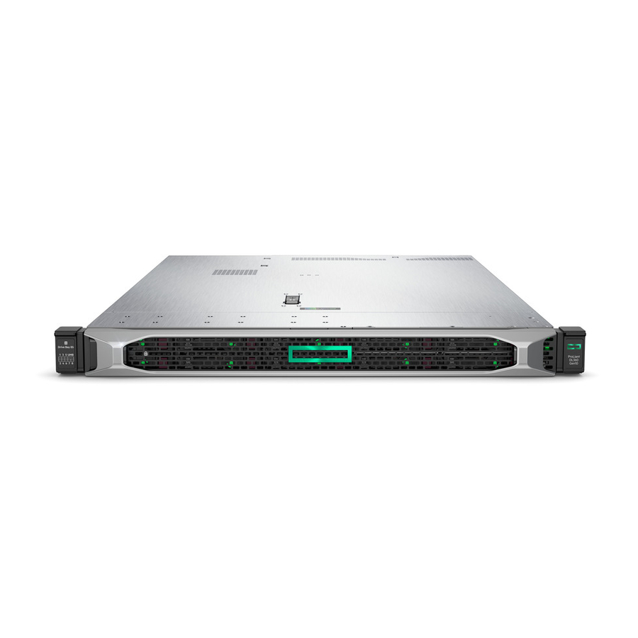
Page 207: Front Panel Components
Front panel components Front panel components 8 SFF 8 SFF Item Item Description Description Serial label pull tab Display port (optional) Optical drive (optional) USB 2.0 port (optional) USB 3.0 port iLO Service Port The operating system does not recognize this port as a USB port. - Page 208 10 SFF NVMe/SAS Combo 10 SFF NVMe/SAS Combo Item Item Description Description Serial label pull tab Systems Insight Display (optional) USB 3.0 port SAS/SATA/NVMe drive bays When the 10 SFF NVMe/SAS backplane option is installed, NVMe drives must be installed in bays 9 and 10.
-
Page 209: Front Panel Leds And Buttons
Front panel LEDs and buttons Front panel LEDs and buttons 8 SFF/10 SFF 8 SFF/10 SFF Item Item Description Description Status Status UID button/LED Solid blue = Activated Flashing blue: 1 Hz = Remote management or firmware upgrade in progress 4 Hz = iLO manual reboot sequence initiated 8 Hz = iLO manual reboot sequence in progress Off = Deactivated... - Page 210 Item Item Description Description Status Status UID button/LED Solid blue = Activated. Flashing blue: 1 Hz = Remote management or firmware upgrade in progress. 4 Hz = iLO manual reboot sequence initiated. 8 Hz = iLO manual reboot sequence in progress. Off = Deactivated.
-
Page 211: Uid Button Functionality
The UID button can be used to display the Server Health Summary when the server will not power on. For more information, see the latest HPE iLO 5 User Guide on the Hewlett Packard Enterprise website Hewlett Packard Enterprise website . -
Page 212: Front Panel Led Power Fault Codes
Front panel LED power fault codes Front panel LED power fault codes The following table provides a list of power fault codes, and the subsystems that are affected. Not all power faults are used by all servers. Subsystem Subsystem LED behavior LED behavior System board 1 flash... -
Page 213: Systems Insight Display Leds
Systems Insight Display LEDs Systems Insight Display LEDs The Systems Insight Display LEDs represent the system board layout. The display enables diagnosis with the access panel installed. Description Description Status Status Processor LEDs Off = Normal Amber = Failed processor DIMM LEDs Off = Normal Amber = Failed DIMM or configuration issue... - Page 214 Description Description Status Status Power cap LED Off = System is in standby, or no cap is set. Solid green = Power cap applied For Networking Choice (NC) server models, the embedded NIC ports are not equipped on the server. Therefore, the NIC LEDs on the Systems Insight Display will flash based on the FlexibleLOM network port activity.
-
Page 215: Systems Insight Display Combined Led Descriptions
Systems Insight Display combined LED descriptions Systems Insight Display combined LED descriptions The combined illumination of the following LEDs indicates a system condition: Systems Insight Display LEDs System power LED Health LED Systems Insight Display Systems Insight Display Health Health System System Status... - Page 216 Systems Insight Display Systems Insight Display Health Health System System Status Status LED and color LED and color power LED power LED Power cap (green) — Flashing Waiting for power. green Power cap (green) — Green Power is available. Power cap (flashing —...
-
Page 217: Rear Panel Components
Rear panel components Rear panel components Item Item Description Description Slot 1 PCIe3 Slot 2 PCIe3 Slot 3 PCIe3 (optional - requires second processor) Power supply 2 (PS2) Power supply 1 (PS1) Video port NIC ports (if equipped) iLO Management Port Serial port (optional) USB 3.0 ports FlexibleLOM (optional) -
Page 218: Rear Panel Leds
Rear panel LEDs Rear panel LEDs Item Item Description Description Status Status UID LED Solid blue = Identification is activated. Flashing blue = System is being managed remotely. Off = Identification is deactivated. iLO 5/standard Solid green = Activity exists. NIC activity LED Flashing green = Activity exists. -
Page 219: System Board Components
System board components System board components Item Item Description Description FlexibleLOM connector Primary (processor 1) PCIe riser connector System maintenance switch Front display port/USB 2.0 connector x4 SATA port 1 x4 SATA port 2 x2 SATA port 3 x1 SATA port 4 Front power/USB 3.0 connector Optical/SATA port 5 Energy pack connector... -
Page 220: System Maintenance Switch Descriptions
System maintenance switch descriptions System maintenance switch descriptions Position Position Default Default Function Function Off = iLO security is enabled. On = iLO security is disabled. Reserved Reserved Reserved Off = Power-on password is enabled. On = Power-on password is disabled. 1 , 2 , 3 Off = No function On = Restore default manufacturing settings... -
Page 221: Nmi Functionality
NMI functionality NMI functionality An NMI crash dump enables administrators to create crash dump files when a system is hung and not responding to traditional debugging methods. An analysis of the crash dump log is an essential part of diagnosing reliability problems, such as hanging operating systems, device drivers, and applications. -
Page 222: Dimm Slot Locations
DIMM slot locations DIMM slot locations DIMM slots are numbered sequentially (1 through 12) for each processor. DIMM slot locations... -
Page 223: Dimm Label Identification
DIMM label identification DIMM label identification To determine DIMM characteristics, see the label attached to the DIMM. The information in this section helps you to use the label to locate specific information about the DIMM. Item Item Description Description Example Example Capacity 8 GB... - Page 224 R = RDIMM (registered) L = LRDIMM (load reduced) E = Unbuffered ECC (UDIMM) For more information about product features, specifications, options, configurations, and compatibility, see the HPE DDR4 SmartMemory QuickSpecs on the Hewlett Packard Enterprise website (https://www.hpe.com/support/DDR4SmartMemoryQS https://www.hpe.com/support/DDR4SmartMemoryQS). DIMM label identification...
-
Page 225: Nvdimm Identification
Data width per DRAM chip x4 (4 bit) Memory type NN4=DDR4 NVDIMM-N Maximum memory speed 2667 MT/s Speed grade V (latency 19-19-19) DIMM type RDIMM (registered) Other — For more information about NVDIMMs, see the product QuickSpecs on the Hewlett Packard Enterprise website (https://www.hpe.com/info/qs https://www.hpe.com/info/qs). NVDIMM identification... -
Page 226: Nvdimm 2D Data Matrix Barcode
NVDIMM 2D Data Matrix barcode NVDIMM 2D Data Matrix barcode The 2D Data Matrix barcode is on the right side of the NVDIMM label and can be scanned by a cell phone or other device. When scanned, the following information from the label can be copied to your cell phone or device: (P) is the module part number. -
Page 227: Nvdimm Led Identification
NVDIMM LED identification NVDIMM LED identification Item LED description Item LED description LED color LED color Power LED Green Function LED Blue NVDIMM LED identification... -
Page 228: Nvdimm-N Led Combinations
NVDIMM-N LED combinations NVDIMM-N LED combinations State State Definition Definition NVDIMM-N Power LED (green) NVDIMM-N Power LED (green) NVDIMM-N Function LED (blue) NVDIMM-N Function LED (blue) AC power is on (12V rail) but the NVM controller is not working or not ready. AC power is on (12V rail) and the NVM controller is ready. -
Page 229: Nvdimm Function Led Patterns
NVDIMM Function LED patterns NVDIMM Function LED patterns For the purpose of this table, the NVDIMM-N LED operates as follows: Solid indicates that the LED remains in the on state. Flashing indicates that the LED is on for 2 seconds and off for 1 second. Fast-flashing indicates that the LED is on for 300 ms and off for 300 ms. -
Page 230: Intel Optane Persistent Memory 100 Series For Hpe Label Identification
QR code Includes part number and serial number For more information about product features, specifications, options, configurations, and compatibility, see the product QuickSpecs on the Hewlett Packard Enterprise website (https://www.hpe.com/support/persistentmemoryQS https://www.hpe.com/support/persistentmemoryQS). Intel Optane persistent memory 100 series for HPE label identification... -
Page 231: Processor, Heatsink, And Socket Components
Processor, heatsink, and socket components Processor, heatsink, and socket components Item Item Description Description Heatsink nuts Processor carrier Pin 1 indicator Heatsink guide/keying feature Alignment post Heatsink keying frame Symbol also on the processor and frame. Processor, heatsink, and socket components... -
Page 232: Device Numbers
Device numbers Device numbers 8 SFF device bay numbering 8 SFF device bay numbering 8 SFF + 2 SFF device bay numbering 8 SFF + 2 SFF device bay numbering Item Item Description Description Box 1, bays 1-8 Box 2, bays 1 and 2 4 LFF device bay numbering 4 LFF device bay numbering 10 SFF NVMe/SAS backplane option device bay numbering... - Page 233 Optional rear device bay numbering The optional rear device bay supports either 1 SFF drive in a SmartDrive carrier, or 2 uFF M.2 drives in an HPE Smart Carrier M.2 (SCM). When the HPE SFF Flash Adapter is installed, the uFF drives are recognized as 1 and 101.
-
Page 234: Hot-Plug Drive Led Definitions
Hot-plug drive LED definitions Hot-plug drive LED definitions Item Item Status Status Definition Definition Locate Solid blue The drive is being identified by a host application. Flashing blue The drive carrier firmware is being updated or requires an update. Activity ring Rotating green Drive activity. -
Page 235: Smart Carrier Nvme (Scn) Drive Led Definitions
Smart Carrier NVMe (SCN) drive LED definitions Smart Carrier NVMe (SCN) drive LED definitions The NVMe drive is a PCIe bus device. A device attached to a PCIe bus cannot be removed without allowing the device and bus to complete and cease the signal/traffic flow. CAUTION: Do not remove an NVMe drive from the drive bay while the Do not remove LED is flashing. - Page 236 Smart Carrier NVMe (SCN) drive LED definitions...
- Page 237 HPE Basic Drive LED definitions Basic Drive LED definitions LFF low-profile drive carrier low-profile drive carrier The LFF low-profile drive carrier supports hot-plug SAS and SATA drives. SFF basic drive carrier basic drive carrier The SFF basic drive carrier supports hot-plug SAS, SATA, and NVMe drives.
-
Page 238: Hpe Basic Drive Led Definitions
HPE Basic Drive LED definitions... -
Page 239: Uff Drive Components And Leds
uFF drive components and LEDs uFF drive components and LEDs Item Item Description Description Status Status Locate Off—Normal Solid blue—The drive is being identified by a host application Flashing blue—The drive firmware is being updated or requires an update uFF drive ejection latch Removes the uFF drive when released Do not remove LED Off—OK to remove the drive. -
Page 240: Hot-Plug Fans
The high performance fans are used for 8 SFF +2 SFF NVMe and 10 SFF drive configurations when NVMe drives are installed in the server. They are also required for ASHRAE-compliant configurations. For more information on ASHRAE-compliant configurations, see the Hewlett Packard Enterprise website https://www.hpe.com/servers/ASHRAE https://www.hpe.com/servers/ASHRAE. - Page 241 BIOS/Platform Configuration (RBSU). Hot-plug fans...
-
Page 242: Hpe Smart Array P824I-P Mr Gen10 Controller
HPE Smart Array P824i-p MR Gen10 Controller HPE Smart Array P824i-p MR Gen10 Controller Components Components Item Description Item Description Internal SAS port 1i Internal SAS port 2i Internal SAS port 3i Internal SAS port 4i Controller backup power cable connector... -
Page 243: Hpe Ns204I-P Nvme Os Boot Device Components
HPE NS204i-p NVMe OS Boot Device NS204i-p NVMe OS Boot Device components components Item Item Description Description Drive bay 1 Drive bay 2 Thermal interface pad with removable liner M.2 drive retaining latches HPE NS204i-p NVMe OS Boot Device components... -
Page 244: Hpe Ns204I-P Nvme Os Boot Device Led Definitions
NS204i-p NVMe OS Boot Device LED definitions LED definitions Item Item Description Fault LED status Description Fault LED status Bay 1 LED Off: Normal Flashing 1Hz: Drive predictive failure Bay 2 LED Amber: Drive failure HPE NS204i-p NVMe OS Boot Device LED definitions... -
Page 245: Hpe Infiniband Hdr/Ethernet 940Qsfp 56X16 Adapter Leds
HPE InfiniBand HDR/Ethernet 940QSFP 56x16 adapter LEDs HPE InfiniBand HDR/Ethernet 940QSFP 56x16 adapter LEDs Link LED status Link LED status Description Description A link has not been established. Solid amber Active physical link exists Blinking amber 4 Hz blinking amber indicates a problem with the physical link. -
Page 246: Dsc-25 2-Port Sfp28 Card Ports And Leds
LEDs The HPE for Pensando DSP DSC-25 2p SFP28 card is a dual-port, single-slot, half-height, half-length (HHHL) SFP28 network adapter. It has LEDs for Link (L) and Activity (A) for each port. A half-height bracket is shown in the following illustration with SFP28 ports and LEDs. - Page 247 Item Item Status Status Description Description SFP Port 2 Link/Activity A link has not been established Solid green Valid Ethernet link Flashing green Passing traffic; flashing frequency indicates traffic intensity Solid amber Link fault System status LED System is not powered Solid amber Power is up, software has not booted yet Solid green...
-
Page 248: Cabling
Cabling Cabling Cabling... -
Page 249: Cabling Overview
Cabling overview Cabling overview This section provides guidelines that help you make informed decisions about cabling the server and hardware options to optimize performance. CAUTION: When routing cables, always be sure that the cables are not in a position where they can be pinched or CAUTION: crimped. -
Page 250: Sff Cables
SFF cables SFF cables Option kit Option kit Cable part number Cable part number Connects from Connects from Connects to Connects to SFF P824i-p Cable Kit 876864-001 8 SFF SAS/SATA Backplane Port 1i/2i on the P824i-p Smart Array Controller 876865-002 2 SFF SAS/SATA Backplane Port 3i on the P824i-p Smart Array Controller... -
Page 251: Sff Configuration Cable Routing
NOTE: NOTE: The following information describes the standard cable routing for this component. For more information on optional cable routing, see the HPE ProLiant DL380 Gen10 Servercabling matrix on the Hewlett Packard Enterprise website (https://www.hpe.com/info/CablingMatrixGen10 https://www.hpe.com/info/CablingMatrixGen10). SFF configuration cable routing... -
Page 252: Sff Backplane To P824I-P Controller
SFF backplane to P824i-p controller SFF backplane to P824i-p controller 8 SFF to ports 1i/2i in the primary 8 SFF to ports 1i/2i in the primary 8 SFF to ports 1i/2i + 2 SFF to port 3i in the primary 8 SFF to ports 1i/2i + 2 SFF to port 3i in the primary 10 SFF premium backplane to ports 1i/2i in the primary 10 SFF premium backplane to ports 1i/2i in the primary... - Page 253 SFF backplane to P824i-p controller...
-
Page 254: Sff Backplane To A P408I-A/P816I-A Controller
8 SFF backplane to a P408i-a/P816i-a controller 8 SFF backplane to a P408i-a/P816i-a controller A P408i-a controller is shown, but the routing is the same for the P816i-a. 8 SFF backplane to a P408i-a/P816i-a controller... -
Page 255: Sff Backplane To P816I-A Controller
2 SFF backplane to P816i-a controller 2 SFF backplane to P816i-a controller 2 SFF backplane to P816i-a controller... -
Page 256: 10 Sff Nvme Backplane To Nvme Riser
10 SFF NVMe backplane to NVMe riser 10 SFF NVMe backplane to NVMe riser 10 SFF NVMe backplane to NVMe riser... -
Page 257: Sff Nvme Backplane To Primary Riser
2 SFF NVMe backplane to primary riser 2 SFF NVMe backplane to primary riser 2 SFF NVMe backplane to primary riser... -
Page 258: Sff Rear Backplane To System Board Sata
1 SFF rear backplane to system board SATA 1 SFF rear backplane to system board SATA 1 SFF rear backplane to system board SATA... -
Page 259: 10 Sff Backplane To P408I-A Controller
10 SFF backplane to P408i-a controller 10 SFF backplane to P408i-a controller 10 SFF backplane to P408i-a controller... -
Page 260: Additional Sff Cabling
Additional SFF cabling Additional SFF cabling For more information on the following cables and cabling configurations, see the HPE DL360 Gen10 Server cabling matrix on the Hewlett Packard Enterprise website (https://www.hpe.com/info/CablingMatrixGen10 https://www.hpe.com/info/CablingMatrixGen10): 8 SFF backplane to P408i-p controller 8 SFF backplane to system board SATA... -
Page 261: Lff Cables
4 LFF backplane Type -p Smart Array controller, slot 1 Type -a Smart Array controller Embedded SATA 874616-001 4 LFF backplane PCI controller, slot 2 HPE Gen9 LFF Optical Cable Kit 756914-001 LFF optical drive System board SATA, port 5 LFF cables... -
Page 262: Lff Configuration Cable Routing
NOTE: NOTE: The following information describes the standard cable routing for this component. For more information on optional cable routing, see the HPE ProLiant DL380 Gen10 Servercabling matrix on the Hewlett Packard Enterprise website (https://www.hpe.com/info/CablingMatrixGen10 https://www.hpe.com/info/CablingMatrixGen10). LFF configuration cable routing... -
Page 263: Lff Backplane To P408I-A Controller
4 LFF backplane to P408i-a controller 4 LFF backplane to P408i-a controller 4 LFF backplane to P408i-a controller... -
Page 264: Additional Lff Cabling
Additional LFF cabling Additional LFF cabling For more information on the following cables and cabling configurations, see the HPE DL360 Gen10 Server cabling matrix on the Hewlett Packard Enterprise website (https://www.hpe.com/info/CablingMatrixGen10 https://www.hpe.com/info/CablingMatrixGen10): 4 LFF backplane to P408i-p controller 4 LFF backplane to system board SATA... -
Page 265: Specifications
Specifications Specifications Specifications... -
Page 266: Environmental Specifications
Environmental specifications Environmental specifications Specification Specification Value Value Temperature range Temperature range — Operating 10°C to 35°C (50°F to 95°F) Nonoperating -30°C to 60°C (-22°F to 140°F) Relative humidity (noncondensing) Relative humidity (noncondensing) — Operating Minimum to be the higher (more moisture) of -12°C (10.4°F) dew point or 8% relative humidity Maximum to be 24°C (75.2°F) dew point or 90% relative humidity Nonoperating... -
Page 267: Server Specifications
Server specifications Server specifications Specification Specification Value Value Height 4.29 cm (1.69 in) Depth (chassis with SFF 70.7 cm (27.83 in) drive cage) Depth (chassis with LFF 74.98 cm (29.50 in) drive cage) Width 43.46 cm (17.11 in) Weights Weights SFF minimum (one drive, one 13.04 kg (28.74 lb) processor, one power supply,... -
Page 268: Power Supply Specifications
HPE 800W Flex Slot Universal Hot-plug Low Halogen Power Supply HPE 800W Flex Slot -48VDC Hot-plug Low Halogen Power Supply HPE 1600 W Flex Slot Platinum Hot-plug Low Halogen Power Supply For detailed power supply specifications, see the QuickSpecs on the Hewlett Packard Enterprise website (https://www.hpe.com/info/proliant/powersupply... -
Page 269: Hpe 500W Flex Slot Platinum Hot-Plug Low Halogen Power Supply
HPE 500W Flex Slot Platinum Hot-plug Low Halogen Power Supply HPE 500W Flex Slot Platinum Hot-plug Low Halogen Power Supply Specification Specification Value Value Input requirements Input requirements — Rated input voltage 100 VAC to 240 VAC 240 VDC for China only... -
Page 270: Hpe 800W Flex Slot Platinum Hot-Plug Low Halogen Power Supply
HPE 800W Flex Slot Platinum Hot-plug Low Halogen Power Supply HPE 800W Flex Slot Platinum Hot-plug Low Halogen Power Supply Specification Specification Value Value Input requirements Input requirements — Rated input voltage 100 VAC to 127 VAC 200 VAC to 240 VAC... -
Page 271: Hpe 800W Flex Slot Titanium Hot-Plug Low Halogen Power Supply
HPE 800W Flex Slot Titanium Hot-plug Low Halogen Power Supply HPE 800W Flex Slot Titanium Hot-plug Low Halogen Power Supply Specification Specification Value Value Input requirements Input requirements — Rated input voltage 200 VAC to 240 VAC 240 VDC for China only... -
Page 272: Hpe 800W Flex Slot Universal Hot-Plug Low Halogen Power Supply
HPE 800W Flex Slot Universal Hot-plug Low Halogen Power Supply HPE 800W Flex Slot Universal Hot-plug Low Halogen Power Supply Specification Specification Value Value Input requirements Input requirements — Rated input voltage 200 VAC to 277 VAC 380 VDC Rated input frequency... -
Page 273: Hpe 800W Flex Slot -48Vdc Hot-Plug Low Halogen Power Supply
HPE 800W Flex Slot -48VDC Hot-plug Low Halogen Power Supply HPE 800W Flex Slot -48VDC Hot-plug Low Halogen Power Supply Specification Specification Value Value Input requirements Input requirements — Rated input voltage -40 VDC to -72 VDC -48 VDC nominal input Rated input current 22.1 A at -40 VDC input... -
Page 274: Hpe 1600 W Flex Slot Platinum Hot-Plug Low Halogen Power Supply
HPE 1600 W Flex Slot Platinum Hot-plug Low Halogen Power Supply HPE 1600 W Flex Slot Platinum Hot-plug Low Halogen Power Supply Specification Specification Value Value Input requirements Input requirements — Rated input voltage 200 VAC to 240 VAC 240 VDC for China only... -
Page 275: Hot-Plug Power Supply Calculations
Hot-plug power supply calculations Hot-plug power supply calculations For hot-plug power supply specifications and calculators to determine electrical and heat loading for the server, see the Hewlett Packard Enterprise Power Advisor website (https://www.hpe.com/info/poweradvisor/online https://www.hpe.com/info/poweradvisor/online). Hot-plug power supply calculations... -
Page 276: Websites
Websites Websites General websites General websites Hewlett Packard Enterprise Information Library https://www.hpe.com/info/EIL https://www.hpe.com/info/EIL Single Point of Connectivity Knowledge (SPOCK) Storage compatibility matrix https://www.hpe.com/storage/spock https://www.hpe.com/storage/spock Storage white papers and analyst reports https://www.hpe.com/storage/whitepapers https://www.hpe.com/storage/whitepapers For additional websites, see Support and other resources. -
Page 277: Support And Other Resources
Support and other resources Support and other resources Support and other resources... -
Page 278: Accessing Hewlett Packard Enterprise Support
Accessing Hewlett Packard Enterprise Support Accessing Hewlett Packard Enterprise Support For live assistance, go to the Contact Hewlett Packard Enterprise Worldwide website: https://www.hpe.com/info/assistance https://www.hpe.com/info/assistance To access documentation and support services, go to the Hewlett Packard Enterprise Support Center website: https://www.hpe.com/support/hpesc https://www.hpe.com/support/hpesc... -
Page 279: Accessing Updates
Enterprise Support Center More Information on Access to Support Materials page: https://www.hpe.com/support/AccessToSupportMaterials https://www.hpe.com/support/AccessToSupportMaterials IMPORTANT: IMPORTANT: Access to some updates might require product entitlement when accessed through the Hewlett Packard Enterprise Support Center. You must have an HPE Passport set up with relevant entitlements. Accessing updates... -
Page 280: Remote Support
HPE Datacenter Care services https://www.hpe.com/services/datacentercare https://www.hpe.com/services/datacentercare HPE Proactive Care service: Supported products list https://www.hpe.com/services/proactivecaresupportedproducts https://www.hpe.com/services/proactivecaresupportedproducts HPE Proactive Care advanced service: Supported products list https://www.hpe.com/services/proactivecareadvancedsupportedproducts https://www.hpe.com/services/proactivecareadvancedsupportedproducts Proactive Care customer information Proactive Care customer information Proactive Care central https://www.hpe.com/services/proactivecarecentral https://www.hpe.com/services/proactivecarecentral Proactive Care service activation https://www.hpe.com/services/proactivecarecentralgetstarted... -
Page 281: Warranty Information
Warranty information Warranty information To view the warranty information for your product, see the links provided below: HPE ProLiant and IA-32 Servers and Options https://www.hpe.com/support/ProLiantServers-Warranties https://www.hpe.com/support/ProLiantServers-Warranties HPE Enterprise and Cloudline Servers https://www.hpe.com/support/EnterpriseServers-Warranties https://www.hpe.com/support/EnterpriseServers-Warranties HPE Storage Products https://www.hpe.com/support/Storage-Warranties https://www.hpe.com/support/Storage-Warranties HPE Networking Products https://www.hpe.com/support/Networking-Warranties... -
Page 282: Regulatory Information
Regulatory information To view the regulatory information for your product, view the Safety and Compliance Information for Server, Storage, Power, Networking, and Rack Products, available at the Hewlett Packard Enterprise Support Center: https://www.hpe.com/support/Safety-Compliance-EnterpriseProducts https://www.hpe.com/support/Safety-Compliance-EnterpriseProducts Additional regulatory information Additional regulatory information Hewlett Packard Enterprise is committed to providing our customers with information about the chemical substances in our products as needed to comply with legal requirements such as REACH (Regulation EC No 1907/2006 of the European Parliament and the Council). - Page 283 Documentation feedback Hewlett Packard Enterprise is committed to providing documentation that meets your needs. To help us improve the documentation, send any errors, suggestions, or comments to Documentation Feedback (docsfeedback@hpe.com docsfeedback@hpe.com). When submitting your feedback, include the document title, part number, edition, and publication date located on the front cover of the document. For online help content, include the product name, product version, help edition, and publication date located on the legal notices page.
Need help?
Do you have a question about the ProLiant DL360 and is the answer not in the manual?
Questions and answers