
Related Manuals for HPE ProLiant DL20 Gen10


Summary of Contents for HPE ProLiant DL20 Gen10
- Page 1 HPE ProLiant DL20 Gen10 Server User Guide HPE ProLiant DL20 Gen10 Server User Guide Part Number: 30-5C1DC581-005 Published: August 2021 Edition: 5...
- Page 2 HPE ProLiant DL20 Gen10 Server User Guide HPE ProLiant DL20 Gen10 Server User Guide Abstract Abstract This document is for the person who installs, administers, and troubleshoots servers and storage systems. Hewlett Packard Enterprise assumes you are qualified in the servicing of computer equipment and trained in recognizing hazards in products with hazardous energy levels, and are familiar with the weight and stability precautions for rack installations.
-
Page 3: Table Of Contents
2.8 Install the access panel 2.9 Remove the riser cage 2.10 Install the riser cage 3 Setup 3.1 Initial server installation 3.1.1 HPE Installation Service 3.1.2 Setting up the server 3.2 Operational requirements 3.2.1 Space and airflow requirements 3.2.2 Temperature requirements 3.2.3 Power requirements... - Page 4 4.12 Storage controller options 4.12.1 Installing a modular Smart Array controller option (type-a, AROC) 4.12.2 Installing a Smart Array standup storage controller 4.12.3 Configuring an HPE Smart Array Gen10 controller 4.13 Energy pack option 4.13.1 HPE Smart Storage Battery 4.13.2 Installing an energy pack...
- Page 5 4.18 HPE Trusted Platform Module 2.0 Gen10 option 4.18.1 Overview 4.18.2 HPE Trusted Platform Module 2.0 guidelines 4.18.3 Installing and enabling the HPE TPM 2.0 Gen10 option 4.18.3.1 Installing the Trusted Platform Module board 4.18.3.1.1 Preparing the server for installation 4.18.3.1.2 Installing the TPM board and cover...
- Page 6 6.8 Scripting Toolkit for Windows and Linux 6.9 UEFI System Utilities 6.9.1 Selecting the boot mode 6.9.2 Secure Boot 6.9.3 Launching the Embedded UEFI Shell 6.10 HPE Smart Storage Administrator 6.11 HPE InfoSight for servers 6.12 USB support 6.12.1 External USB functionality 6.13 Redundant ROM support 6.13.1 Safety and security benefits...
- Page 7 10.3.1 ATX 290 W Non-hot-plug Power Supply (92% efficiency) 10.3.2 ATX 290 W Platinum Non-hot-plug Power Supply (94% efficiency) 10.3.3 HPE 500 W Flex Slot Platinum Hot-plug Low Halogen Power Supply 10.3.4 HPE 800W Flex Slot -48VDC Hot plug Low Halogen Power Supply...
-
Page 8: Component Identification
Component identification Component identification Component identification... -
Page 9: Front Panel Components
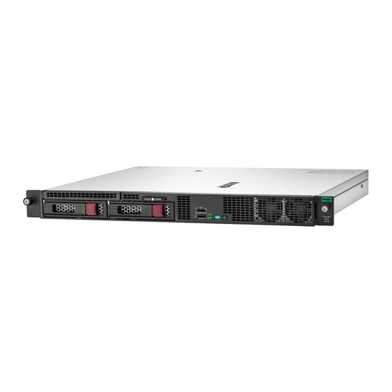
Front panel components Front panel components Two-bay LFF non-hot-plug drive model Two-bay LFF non-hot-plug drive model Item Item Description Description Optical drive (optional) Serial number/iLO information pull tab iLO Service Port USB 3.0 port LFF non-hot-plug drive cage Two-bay LFF hot-plug drive model Two-bay LFF hot-plug drive model Item Item... - Page 10 Item Item Description Description Media bay Serial number/iLO information pull tab iLO Service Port USB 3.0 port SFF hot-plug drives The media drive bay supports an optical drive or a two-bay SFF drive cage. Six-bay SFF hot-plug drive model Six-bay SFF hot-plug drive model Item Item Description...
-
Page 11: Serial Number/Ilo Information Pull Tab
The serial number/iLO information pull tab is double-sided. One side shows the server serial number and the customer asset tag label. The other side shows the default iLO account information and QR code label. Use a mobile device to scan the QR code label to display the server mobile product page ( https://www.hpe.com/qref/dl20gen10 https://www.hpe.com/qref/dl20gen10). This page contains links to server setup information, spare part numbers, QuickSpecs, troubleshooting resources, and other useful product links. -
Page 12: Front Panel Leds And Buttons
Front panel LEDs and buttons Front panel LEDs and buttons Item Item Description Description Status Status Definition Definition Health LED Solid green Normal Flashing green iLO is rebooting Flashing amber System degraded Flashing red System critical NIC status LED Solid green Linked to network Flashing green Network active... -
Page 13: Server Uid Led
Server UID LED Server UID LED The UID LED is used to locate a particular server when it is deployed in a dense rack with other equipment. Activating the UID LED helps an on-site technician to quickly identify a server for maintenance tasks. Server UID LED... -
Page 14: Uid Button Functionality
UID button functionality The UID button can be used to display the Server Health Summary when the server will not power on. For more information, see the iLO user guide on the Hewlett Packard Enterprise website (https://www.hpe.com/support/ilo-docs https://www.hpe.com/support/ilo-docs). UID button functionality... -
Page 15: Front Panel Led Power Fault Codes
Front panel LED power fault codes Front panel LED power fault codes The following table provides a list of power fault codes, and the subsystems that are affected. Not all power faults are used by all servers. Subsystem Subsystem LED behavior LED behavior System board 1 flash... -
Page 16: Rear Panel Components
Rear panel components Rear panel components Item Item Description Description Slot 1 PCIe3 x8 (8, 4, 1)/FlexibleLOM slot Slot 2 PCIe3 x8 (8, 4, 1) Serial port (optional) Non-hot-plug power supply Hot-plug power supply bay 1 (optional) Hot-plug power supply bay 2 (optional) USB 3.0 ports (2) NIC port 2 NIC 1/iLO Shared Network Port... -
Page 17: Rear Panel Leds
Rear panel LEDs Rear panel LEDs Item Item Status Status Definition Definition Solid blue Activated Flashing blue System is being managed remotely. Deactivated Power supply Solid green Normal System is off or power supply has failed. NIC/iLO status Solid green Linked to network Flashing green Network active... -
Page 18: System Board Components
System board components System board components Item Item Description Description PCIe riser connector System maintenance switch M.2 SSD slot Controller backup power connector for slot 1 Fan connector 2 Fan connector 1 System battery Chassis intrusion detection switch Non-hot-plug or Flexible Slot power supply connector Two-bay SFF drive sideband connector Energy pack connector Non-hot-plug or Flexible Slot power supply sideband connector... - Page 19 Item Item Description Description Fan connector 3 Controller backup power connector for slot 2 TPM connector Smart Array modular controller connector (AROC) Internal USB 3.0 connector For more information on the supported riser board slots, see PCIe riser slot definitions System board components...
-
Page 20: System Maintenance Switch Descriptions
System maintenance switch descriptions System maintenance switch descriptions Position Position Default Default Function Function Off = iLO 5 security is enabled. On = iLO 5 security is disabled. Reserved Reserved Reserved Off = Power-on password is enabled. On = Power-on password is disabled. 1 , 2 , 3 Off = No function On = Restore default manufacturing settings... -
Page 21: Dimm Slot Locations
DIMM slot locations DIMM slot locations The arrow in the illustration points to the front of the server. DIMM slot locations... -
Page 22: Dimm Label Identification
DIMM label identification DIMM label identification To determine DIMM characteristics, see the label attached to the DIMM. The information in this section helps you to use the label to locate specific information about the DIMM. Item Item Description Description Example Example Capacity 8 GB... - Page 23 R = RDIMM (registered) L = LRDIMM (load reduced) E = Unbuffered ECC (UDIMM) For more information about product features, specifications, options, configurations, and compatibility, see the HPE DDR4 SmartMemory QuickSpecs on the Hewlett Packard Enterprise website (https://www.hpe.com/support/DDR4SmartMemoryQS https://www.hpe.com/support/DDR4SmartMemoryQS). DIMM label identification...
-
Page 24: Pcie Riser Slot Definitions
PCIe riser slot definitions PCIe riser slot definitions FlexibleLOM riser board FlexibleLOM riser board Item Item Description Description Supported options Supported options FlexibleLOM slot, PCIe3 x8 (with NCSI) FlexibleLOM adapter Slot 2, PCIe3 x16 (8,4,1) Full-height, half-length expansion boards Two-slot PCIe riser board Two-slot PCIe riser board Item Item... -
Page 25: Drive Led Definitions
Drive LED definitions Drive LED definitions Drive LED definitions... -
Page 26: Low-Profile Lff Drive Led Definitions
Low-profile LFF drive LED definitions Low-profile LFF drive LED definitions Item Item Status Status Definition Definition Fault\Locate Solid amber The drive has failed. Solid blue The drive is operating normally and being identified by a management application. Flashing amber/blue The drive has failed, or a predictive failure alert has been received for this (1 flash per second) drive;... -
Page 27: Smart Carrier (Sc) Drive Led Definitions
Smart Carrier (SC) drive LED definitions Smart Carrier (SC) drive LED definitions Item Item Status Status Definition Definition Locate Solid blue The drive is being identified by a host application. Flashing blue The drive carrier firmware is being updated or requires an update. Activity Rotating green Drive activity... -
Page 28: Drive Bay Numbering
Drive bay numbering Drive bay numbering Two-bay LFF non-hot-plug drive model Two-bay LFF non-hot-plug drive model Two-bay LFF hot-plug drive model Two-bay LFF hot-plug drive model Four-bay SFF hot-plug drive model Four-bay SFF hot-plug drive model Six-bay SFF hot-plug drive model Six-bay SFF hot-plug drive model Drive bay numbering... -
Page 29: Fan Bay Numbering
Fan bay numbering Fan bay numbering To provide sufficient airflow to the system, the server is by default populated by three fans. Fan bay numbering... -
Page 30: Fan Mode Behavior
Fan mode behavior Fan mode behavior The server supports nonredundant fan mode. If a fan fails or is missing, the following behaviors are exhibited: The health LED flashes red. The operating system performs a graceful shutdown. Fan mode behavior... -
Page 31: Operations
Operations Operations Operations... -
Page 32: Power Up The Server
Power up the server Power up the server To power up the server, use one of the following methods: Press the Power On/Standby button. Use the virtual power button through iLO. Power up the server... -
Page 33: Power Down The Server
Power down the server Power down the server Before powering down the server for any upgrade or maintenance procedures, perform a backup of critical server data and programs. IMPORTANT: IMPORTANT: When the server is in standby mode, auxiliary power is still being provided to the system. To power down the server, use one of the following methods: Press and release the Power On/Standby button. -
Page 34: Remove The Front Bezel
Remove the front bezel Remove the front bezel Procedure Procedure 1. If installed, unlock and remove the Kensington security lock. For more information, see the lock documentation. 2. Press and hold the front bezel latch. 3. Open the front bezel. 4. -
Page 35: Extend The Server From The Rack
Extend the server from the rack Extend the server from the rack WARNING: WARNING: To reduce the risk of personal injury or equipment damage, be sure that the rack is adequately stabilized before extending a component from the rack. Prerequisites Prerequisites Before you perform this procedure, make sure that you have a T-25 Torx screwdriver available. - Page 36 6. Extend the server on the rack rails until the server rail-release latches are engaged. Extend the server from the rack...
-
Page 37: Remove The Server From The Rack
Remove the server from the rack Remove the server from the rack WARNING: This server is heavy. To reduce the risk of personal injury or damage to the WARNING: equipment: Observe local occupational health and safety requirements and guidelines for manual material handling. -
Page 38: Install The Server Into The Rack
Install the server into the rack Install the server into the rack Prerequisites Prerequisites Before you perform this procedure, make sure that you have a T-25 Torx screwdriver available. Procedure Procedure 1. Install the server into the rack: a. Insert the server sliding rails into the rack mounting rails. b. - Page 39 3. Connect the peripheral devices to the server. For information on identifying I/O ports, see Rear panel components. 4. For a hot-plug power supply: For a hot-plug power supply: To prevent accidental power cord disconnection when sliding the server in and out of the rack, secure the power cord in the strain relief strap attached to the power supply handle: a.
- Page 40 a. Pull the release tab and then slide the clip backward to avoid having the power cord connection blocked by the clip. b. Connect the power cord to the power supply. c. Press the top part of the clip, and then pull the clip open. d.
- Page 41 6. To secure the power cords and other rear panel cables to the rack rail, use the hook-and-loop strap. 7. Connect each power cord to the power source. 8. Power up the server . Install the server into the rack...
-
Page 42: Remove The Access Panel
Remove the access panel Remove the access panel WARNING: To reduce the risk of personal injury from hot surfaces, allow the drives and the WARNING: internal system components to cool before touching them. CAUTION: To prevent damage to electrical components, take the appropriate anti-static precautions before beginning CAUTION: any installation, removal, or replacement procedure. -
Page 43: Install The Access Panel
Install the access panel Install the access panel Prerequisites Prerequisites Before you perform this procedure, make sure that you have a T-15 Torx screwdriver available. Procedure Procedure 1. With access panel latch open, insert the guide pin on the chassis through the hole on the access panel latch. 2. -
Page 44: Remove The Riser Cage
Remove the riser cage Remove the riser cage CAUTION: CAUTION: To prevent damage to the server or expansion boards, power down the server, and disconnect all power cords before removing or installing the riser cage. Procedure Procedure 1. If installed, remove the front bezel . 2. -
Page 45: Install The Riser Cage
Install the riser cage Install the riser cage CAUTION: CAUTION: To prevent damage to the server or expansion boards, power down the server, and disconnect all power cords before removing or installing the riser cage. Procedure Procedure 1. Connect all necessary internal cabling to the expansion board. 2. -
Page 46: Setup
Setup Setup Setup... -
Page 47: Initial Server Installation
Depending on the technical expertise of the user and the complexity of the product, for the initial server installation, the user can choose Order the HPE Installation Service. Perform the initial server setup procedure. Initial server installation... -
Page 48: Hpe Installation Service
HPE-supported products from other vendors that are sold by HPE or by HPE authorized resellers. The Installation Service is part of a suite of HPE deployment services that are designed to give users the peace of mind that comes from knowing that their HPE and HPE- supported products have been installed by an HPE specialist. -
Page 49: Setting Up The Server
Extract it from the SPP. Read the HPE UEFI requirements for ProLiant servers on the HPE website: http://www.hpe.com/support/Gen10UEFI http://www.hpe.com/support/Gen10UEFI If the UEFI requirements are not met, you might experience boot failures or other errors when installing the operating system. - Page 50 For Intelligent Provisioning 3.30 and later, you are prompted to select whether you want to enter the Intelligent Provisioning or HPE Rapid Setup Software mode. After you have selected a mode, you must reprovision the server to change the mode that launches when you boot to F10.
- Page 51 Press F11 at boot screen to select the boot device. c. After the OS installed, update the drivers. Register the server Register the server 9. To experience quick service and efficient support, register the server at the HPE website: https://myenterpriselicense.hpe.com https://myenterpriselicense.hpe.com Setting up the server...
-
Page 52: Operational Requirements
Operational requirements Operational requirements Operational requirements... -
Page 53: Space And Airflow Requirements
Space and airflow requirements Space and airflow requirements To allow for servicing and adequate airflow, observe the following space and airflow requirements when deciding where to install a rack: Leave a minimum clearance of 63.5 cm (25 in) in front of the rack. Leave a minimum clearance of 76.2 cm (30 in) behind the rack. -
Page 54: Temperature Requirements
Temperature requirements Temperature requirements To ensure continued safe and reliable equipment operation, install or position the system in a well-ventilated, climate-controlled environment. The maximum recommended ambient operating temperature (TMRA) for most server products is 35°C (95°F). The temperature in the room where the rack is located must not exceed 35°C (95°F). -
Page 55: Power Requirements
Power requirements Power requirements Installation of this equipment must comply with local and regional electrical regulations governing the installation of information technology equipment by licensed electricians. This equipment is designed to operate in installations covered by NFPA 70, 1999 Edition (National Electric Code) and NFPA-75, 1992 (code for Protection of Electronic Computer/Data Processing Equipment). -
Page 56: Electrical Grounding Requirements
Electrical grounding requirements Electrical grounding requirements The server must be grounded properly for proper operation and safety. In the United States, you must install the equipment in accordance with NFPA 70, National Electric Code Article 250, as well as any local and regional building codes. In Canada, you must install the equipment in accordance with Canadian Standards Association, CSA C22.1, Canadian Electrical Code. -
Page 57: Rack Warnings And Cautions
Rack warnings and cautions Rack warnings and cautions WARNING: WARNING: To reduce the risk of personal injury or equipment damage when unloading a rack: At least two people are needed to safely unload the rack from the pallet. An empty 42U rack can weigh as much as 115 kg (253 lb), can stand more than 2.1 m (7 ft) tall, and might become unstable when being moved on its casters. - Page 58 the installation, consider the following: You must fully understand the static and dynamic load carrying capacity of the rack and be sure that it can accommodate the maximum weight of the server. Be sure sufficient clearance exists for cabling, installation and removal of the server, and movement of the rack doors.
-
Page 59: Server Warnings And Cautions
Server warnings and cautions Server warnings and cautions WARNING: WARNING: To reduce the risk of personal injury, electric shock, or damage to the equipment, disconnect the power cord to remove power from the server. Pressing the Power On/Standby button does not shut off system power completely. -
Page 60: Electrostatic Discharge
Electrostatic discharge Electrostatic discharge Be aware of the precautions you must follow when setting up the system or handling components. A discharge of static electricity from a finger or other conductor may damage system boards or other static-sensitive devices. This type of damage may reduce the life expectancy of the system or component. -
Page 61: Post Screen Options
POST screen options POST screen options When the server is powered on, the POST screen is displayed. The following options are displayed: System Utilities (F9) Use this option to configure the system BIOS. Intelligent Provisioning (F10) Use this option to deploy an operating system or configure storage. Boot menu (F11) Use this option to make a one-time boot selection. -
Page 62: Hardware Options Installation
This chapter provides instructions for installing supported hardware options. To ensure proper server deployment and operation, Hewlett Packard Enterprise recommends installing only HPE‑validated hardware options. To see the list of validated options for this server, see the product QuickSpecs on the HPE ProLiant DL20 Gen10 Server website: https://www.hpe.com/servers/dl20-gen10 https://www.hpe.com/servers/dl20-gen10... -
Page 63: Introduction
Introduction Introduction Install any hardware options before initializing the server. If multiple options are being installed, read the installation instructions for all the hardware options to identify similar steps and streamline the installation process. WARNING: To reduce the risk of personal injury from hot surfaces, allow the drives and the WARNING: internal system components to cool before touching them. -
Page 64: Rack Rail Option
Rack rail option Rack rail option Rack rail option... -
Page 65: Installing The Rack Rail Option
Installing the rack rail option Installing the rack rail option The rack rails can be installed in round-hole, square-hole, or threaded-hole racks. These rails occupy 1U position on the rack. The illustrations used in this section show an icon on the upper right corner of the image. This icon indicates the rack type for which the action illustrated in the image is valid. - Page 66 3. Remove the pins and washers from the mounting rails. 4. Fasten the mounting rails to the rack columns: For round-hole or square-hole racks: Insert the rail pins into the rack column holes. Installing the rack rail option...
- Page 67 For threaded-hole rack: Insert the rail pins into the rack column holes, and then install the mounting screws. 5. Install the server into the rack . 6. To secure the power cords and other rear panel cables to the rack rail, install the hook-and-loop strap. The installation is complete.
-
Page 68: Installing The Rack Rail Hook-And-Loop Strap
Installing the rack rail hook-and-loop strap Installing the rack rail hook-and-loop strap The rack rail hook-and-loop strap can be installed on either the left or right rack rail. Hewlett Packard Enterprise recommends installing it on the left rack rail for better cable management. Procedure Procedure 1. -
Page 69: Installing The Front Bezel Option
Installing the front bezel option Installing the front bezel option Procedure Procedure 1. Attach the front bezel to the latch ear. 2. Press and hold the front bezel latch. 3. Close the front bezel. 4. Install the Kensington security lock. For more information, see the lock documentation. -
Page 70: Drive Options
Drive options Drive options Drive options... -
Page 71: Drive Installation Guidelines
Drive installation guidelines Drive installation guidelines Observe the following general guidelines: The system automatically sets all drive numbers. If only one drive is used, install it in the bay with the lowest drive number. For drive numbering, see Drive bay numbering. Drives with the same capacity provide the greatest storage space efficiency when grouped into the same drive array. -
Page 72: Drive Support Information
Non-hot plug LFF drives Hot-plug LFF drives Hot-plug SFF drives The embedded HPE Smart Array S100i SR Gen10 Controller supports SATA drive installation. For SAS support, install a Smart Array Gen10 type-p or type-a controller option . Drive support information... -
Page 73: Installing An Lff Non-Hot-Plug Drive
Installing an LFF non-hot-plug drive Installing an LFF non-hot-plug drive Prerequisites Prerequisites Before you perform this procedure, make sure that you have the following tools available: T-15 Torx screwdriver Phillips No. 1 screwdriver Procedure Procedure 1. If installed, remove the front bezel . 2. - Page 74 10. Install the non-hot-plug drive. 11. Install the non-hot-plug drive cage assembly. Installing an LFF non-hot-plug drive...
- Page 75 18. If removed, install the front bezel . The installation is complete. To configure arrays, see the HPE Smart Array SR Gen10 Configuration Guide at the Hewlett Packard Enterprise website Hewlett Packard Enterprise website . Installing an LFF non-hot-plug drive...
-
Page 76: Installing An Lff Hot-Plug Drive
6. Determine the status of the drive from the drive LED definitions . The installation is complete. To configure arrays, see the HPE Smart Array SR Gen10 Configuration Guide at the Hewlett Packard Enterprise website Hewlett Packard Enterprise website . -
Page 77: Installing An Sff Hot-Plug Drive
6. Determine the status of the drive from the drive LED definitions . The installation is complete. To configure arrays, see the HPE Smart Array SR Gen10 Configuration Guide at the Hewlett Packard Enterprise website Hewlett Packard Enterprise website . -
Page 78: Power Supply Options
ATX 290 W Platinum Non-hot-plug Power Supply (94% efficiency) ATX 290 W Non-hot-plug Power Supply (92% efficiency) HPE 500 W Flex Slot Platinum Hot-plug Low Halogen Power Supply HPE 800W Flex Slot -48VDC Hot plug Low Halogen Power Supply Power supply options... -
Page 79: Hot-Plug Power Supply Calculations
Hot-plug power supply calculations Hot-plug power supply calculations For more information on the hot-plug power supply and calculators to determine server power consumption in various system configurations, see the Hewlett Packard Enterprise Power Advisor website (https://www.hpe.com/info/poweradvisor/online https://www.hpe.com/info/poweradvisor/online). Hot-plug power supply calculations... -
Page 80: Power Supply Warnings And Cautions
Power supply warnings and cautions Power supply warnings and cautions WARNING: WARNING: To reduce the risk of electric shock or damage to the equipment: Do not disable the power cord grounding plug. The grounding plug is an important safety feature. Plug the power cord into a grounded (earthed) electrical outlet that is easily accessible at all times. -
Page 81: Installing A Redundant Ac Power Supply
Installing a redundant AC power supply Installing a redundant AC power supply WARNING: To reduce the risk of personal injury from hot surfaces, allow the power supply or WARNING: power supply blank to cool before touching it. CAUTION: To prevent improper cooling and thermal damage, do not operate the server unless all bays are populated CAUTION: with either a component or a blank. -
Page 82: Installing A Hot-Plug Dc Power Supply
The following input power cord option might be purchased from an authorized Hewlett Packard Enterprise reseller: J6X43A—HPE 12 AWG 48 V DC 3.0 m Power Cord If you are not using an input power cord option, the power supply cabling should be made in consultation with a licensed electrician and be compliant with local code. - Page 83 2. Remove the ring tongue. 3. Crimp the ring tongue to the ground cable from the -48 V DC power source. Installing a hot-plug DC power supply...
- Page 84 4. Remove the terminal block connector. 5. Loosen the screws on the terminal block connector. Installing a hot-plug DC power supply...
- Page 85 6. Attach the ground (earthed) wire to the ground screw and washer and tighten to 1.47 N m (13 lb-in) of torque. The ground wire must be connected before the -48 V wire and the return wire. The ground wire must be connected before the -48 V wire and the return wire. 7.
- Page 86 8. Insert the return wire into the right side of the connector, and then tighten the screw to 1.3 N m (10 lb-in) of torque. 9. Install the terminal block connector in the power supply. Installing a hot-plug DC power supply...
- Page 87 10. To prevent accidental power cord disconnection when sliding the server in and out of the rack, secure the power cord, wires, and/or cables in the strain relief strap attached to the power supply handle: a. Unwrap the strain relief strap from the power supply handle. CAUTION: Avoid tight bend radii to prevent damaging the internal wires of a power cord or a server cable.
- Page 88 12. Make sure the -48V DC power source is off or the PDU breaker is in the off position. 13. Connect the power cord to the -48V DC power source or PDU. 14. Turn on the -48V power source or switch the PDU breaker to the on position to supply -48V to the power supply. 15.
-
Page 89: Optical Drive Option
Optical drive option Optical drive option Optical drive option... -
Page 90: Installing An Optical Drive In An Lff Chassis
Installing an optical drive in an LFF chassis Installing an optical drive in an LFF chassis Prerequisites Prerequisites Before you perform this procedure, make sure that you have the following tools available: T-10 Torx screwdriver Phillips No. 1 screwdriver Procedure Procedure 1. - Page 91 9. Install the optical drive in the optical drive bay. 10. Connect the optical drive SATA-power Y-cable . 11. Install the access panel . 12. Install the server into the rack . 13. Connect all peripheral cables to the server. 14.
- Page 92 The installation is complete. Installing an optical drive in an LFF chassis...
-
Page 93: Installing An Optical Drive In An Sff Chassis
Installing an optical drive in an SFF chassis Installing an optical drive in an SFF chassis Prerequisites Prerequisites Before you perform this procedure, make sure that you have the following items available: T-10 Torx screwdriver Phillips No. 1 screwdriver Procedure Procedure 1. - Page 94 9. Install the optical drive bracket. 10. Install the optical drive in the optical drive cage. Installing an optical drive in an SFF chassis...
- Page 95 11. Install the optical drive cage assembly in the media bay. 12. Connect the optical drive SATA-power Y-cable . 13. Install the access panel . 14. Install the server into the rack . 15. Connect all peripheral cables to the server. 16.
- Page 96 Installing an optical drive in an SFF chassis...
-
Page 97: Installing The Two-Bay Sff Drive Cage Option
Installing the two-bay SFF drive cage option Installing the two-bay SFF drive cage option Prerequisites Prerequisites Before you perform this procedure, make sure that you have a T-10 Torx screwdriver available. Procedure Procedure 1. If installed, remove the front bezel . 2. - Page 98 9. Install the drives . 10. Connect the drive cables . 11. Install the access panel . 12. Install the server into the rack . 13. Connect all peripheral cables to the server. 14. Connect the power cords: a. Connect each power cord to the server. b.
-
Page 99: Memory Options
Memory options Memory options IMPORTANT: This server does not support mixing RDIMMs and UDIMMs. Attempting to mix any combination of these IMPORTANT: DIMMs can cause the server to halt during BIOS initialization. All memory installed in the server must be of the same type. -
Page 100: Dimm Population Information
DIMM population information DIMM population information For specific DIMM population information, see the DIMM population guidelines on the Hewlett Packard Enterprise website (https://www.hpe.com/docs/standard-population-rules https://www.hpe.com/docs/standard-population-rules ). DIMM population information... -
Page 101: Installing A Dimm
Installing a DIMM Installing a DIMM Procedure Procedure 1. If installed, remove the front bezel . 2. Power down the server. 3. Remove all power: a. Disconnect each power cord from the power source. b. Disconnect each power cord from the server. 4. - Page 102 Installing a DIMM...
-
Page 103: M.2 Ssd/Dedicated Ilo/Serial Port Enablement Option
M.2 SSD/dedicated iLO/serial port enablement option M.2 SSD/dedicated iLO/serial port enablement option The M.2 SSD/dedicated iLO/serial port enablement option adds support for: M.2 NVMe SSD iLO Dedicated Network Port Serial port M.2 SSD/dedicated iLO/serial port enablement option... -
Page 104: M.2 Ssd/Dedicated Ilo/Serial Port Enablement Option Components
M.2 2242 SSD standoff M.2 SSD slot Serial port cable Serial port cable clip This component is not required for installing the M.2 SSD/dedicated iLO/serial port enablement option in the HPE ProLiant DL20 Gen10 Server. M.2 SSD/dedicated iLO/serial port enablement option components... -
Page 105: M.2 Ssd Standoffs In The System Board
M.2 SSD standoffs in the system board M.2 SSD standoffs in the system board Item Item Description Description M.2 22110 SSD standoff M.2 2280 SSD standoff M.2 2242 SSD standoff M.2 SSD slot M.2 SSD standoffs in the system board... -
Page 106: Installing The M.2 Ssd/Dedicated Ilo/Serial Port Enablement Board
Installing the M.2 SSD/dedicated iLO/serial port enablement board Installing the M.2 SSD/dedicated iLO/serial port enablement board Prerequisites Prerequisites Before you perform this procedure, make sure that you have the following tools available: T-15 Torx screwdriver 4.5 mm hex nut screwdriver Procedure Procedure 1. - Page 107 10. Identify the M.2 SSD type to be installed in the enablement board. 11. Remove the system board mounting screw and hex nut corresponding to the M.2 SSD type. Retain these fasteners for future use. 12. Smoothen the mylar tape adjacent to the onboard M.2 SSD slot. Installing the M.2 SSD/dedicated iLO/serial port enablement board...
- Page 108 13. Install the M.2 SSD/dedicated iLO/serial port enablement board: a. Insert the enablement board into the M.2 SSD slot at a 45° angle. b. Carefully press the enablement board down to the horizontal position. c. Install the enablement board screw. 14.
- Page 109 17. Install the access panel . 18. Install the server into the rack . 19. Connect all peripheral cables to the server. 20. Connect the power cords: a. Connect each power cord to the server. b. Connect each power cord to the power source. 21.
-
Page 110: Installing The Serial Port Cable
Installing the serial port cable Installing the serial port cable Prerequisites Prerequisites Before you perform this procedure, make sure that: The M.2 SSD/dedicated iLO/serial port enablement board is installed . 5 mm hex nut screwdriver is available. Procedure Procedure 1. If installed, remove the front bezel . 2. - Page 111 10. Connect the serial port cable to the M.2 SSD/dedicated iLO/serial port enablement board . 11. Install the riser cage. 12. Install the access panel . 13. Install the server into the rack . 14. Connect all peripheral cables to the server. 15.
-
Page 112: Enabling The Dedicated Ilo Management Module
The onboard NIC 1/shared iLO connector is set as the default system iLO connector. To enable the dedicated iLO management module, use the iLO 5 Configuration Utility accessible within the HPE UEFI System Utilities. For more information on the UEFI System Utilities, see the UEFI documentation on the Hewlett Packard Enterprise website ( https://www.hpe.com/servers/uefi). -
Page 113: M.2 Ssd Option
The SmartSSD Wear Gauge reports in the HPE Smart Storage Administrator contain information about the current usage level and remaining expected lifetime of SSDs attached to the system. For more information, see the HPE Smart Array SR Gen10 Configuration Guide at the Hewlett Packard Enterprise website Hewlett Packard Enterprise website . -
Page 114: Installing The M.2 Nvme Ssd On The System Board
This means that RAID configuration for NVMe SSDs is only supported through the operating system. IMPORTANT: IMPORTANT: When installing HPE 400 GB NVMe x4 MU M.2 22110 DS SSD (875583-B21) and HPE 480 GB NVMe x4 RI M.2 22110 DS SSD (875579-001) modules, the supporting ambient temperature should be under 30°C (86°F). Prerequisites... - Page 115 For M.2 22110 SSD installation, remove the Phillips screw. 11. Install the hex standoff on the 2242 or 2280 standoff position on the system board. Installing the M.2 NVMe SSD on the system board...
- Page 116 12. Install an M.2 NVMe SSD on the system board: a. Insert the SSD into the M.2 slot at a 45° angle. b. Carefully press the SSD down to the horizontal position. c. Install the SSD mounting screw. 13. If removed, install the riser cage. 14.
- Page 117 15. Install the access panel . 16. Install the server into the rack . 17. Connect all peripheral cables to the server. 18. Connect the power cords: a. Connect each power cord to the server. b. Connect each power cord to the power source. 19.
-
Page 118: Installing An M.2 Nvme Ssd On The M.2 Ssd/Dedicated Ilo/Serial Port Enablement Board
This means that RAID configuration for NVMe SSDs is only supported through the operating system. IMPORTANT: IMPORTANT: When installing HPE 400 GB NVMe x4 MU M.2 22110 DS SSD (875583-B21) and HPE 480 GB NVMe x4 RI M.2 22110 DS SSD (875579-001) modules, the supporting ambient temperature should be under 30°C (86°F). Prerequisites... - Page 119 11. Install the M.2 NVMe SSD on the enablement board: a. Insert the SSD into the M.2 SSD slot at a 45° angle. b. Carefully press the SSD down to the horizontal position. c. Install the SSD mounting screw. 12. If removed, install the riser cage. 13.
- Page 120 14. Install the access panel . 15. Install the server into the rack . 16. Connect all peripheral cables to the server. 17. Connect the power cords: a. Connect each power cord to the server. b. Connect each power cord to the power source. 18.
-
Page 121: M.2 Sata Ssd Enablement Option
The server supports the installation of M.2 SATA SSD enablement board. The enablement board can support two M.2 SATA SSDs. Use the embedded HPE Smart Array S100i SR Gen10 Controller to manage the M.2 SATA SSDs. The S100i SR Gen10 SW RAID support requires that the server boot mode be set to UEFI. -
Page 122: Installing An M.2 Sata Ssd
Installing an M.2 SATA SSD Installing an M.2 SATA SSD The M.2 SATA expansion board supports 2280 or 22110 M.2 SSDs only. Prerequisites Prerequisites Before you perform this procedure, make sure that you have the following tools available: T-15 Torx screwdriver Phillips No. - Page 123 9. Install the M.2 SATA SSD on the enablement board: a. If only one SSD is being installed, install the SSD in the enablement board slot 1. b. Insert the SSD into the SSD slot at a 45° angle. c. Carefully press the SSD down to the horizontal position. d.
- Page 124 18. If removed, install the front bezel . The installation is complete. To configure the M.2 SATA SSDs, see the HPE Smart Array SR Gen10 Configuration Guide at the Hewlett Packard Enterprise website Hewlett Packard Enterprise website . Installing an M.2 SATA SSD...
-
Page 125: Storage Controller Options
Storage controller options Storage controller options The server supports following storage controllers: For SATA drives only – Embedded HPE Smart Array S100i SR Gen10 Controller For SAS and SATA drives: Type-a modular Smart Array controller (AROC) Type-p standup plug-in Smart Array controller... -
Page 126: Installing A Modular Smart Array Controller Option (Type-A, Aroc)
Installing a modular Smart Array controller option (type-a, AROC) Installing a modular Smart Array controller option (type-a, AROC) Prerequisites Prerequisites Before you perform this procedure, perform the following steps: 1. Back up data on the system. 2. Close all applications. 3. - Page 127 9. Cable the controller . 10. Install the riser cage. 11. Install the access panel . 12. Install the server into the rack . 13. Connect all peripheral cables to the server. 14. Connect the power cords: a. Connect each power cord to the server. b.
-
Page 128: Installing A Smart Array Standup Storage Controller
Installing a Smart Array standup storage controller Installing a Smart Array standup storage controller Prerequisites Prerequisites To determine the slot compatibility for the storage controller, review the PCIe expansion slot population rules . Before you perform this procedure, perform the following steps: 1. - Page 129 b. Install the low-profile bracket on the controller. 10. Remove the riser slot blank. Riser slot 1 Installing a Smart Array standup storage controller...
- Page 130 11. Install the controller. Riser slot 1 Riser slot 2 12. Cable the controller . 13. To enable HPE Smart Array SR SmartCache in a Smart Array type-p Gen10 controller, install an energy pack. Installing a Smart Array standup storage controller...
- Page 131 SmartCache and CacheCade enable solid-state drives to be used as caching devices for hard drive media. These features accelerate access to frequently used data by caching hot data from the hard drives onto the solid-state drives. 14. Install the riser cage. 15.
-
Page 132: Configuring An Hpe Smart Array Gen10 Controller
SPP – See the product documentation on the Hewlett Packard Enterprise website: http://www.hpe.com/info/spp/docs http://www.hpe.com/info/spp/docs UEFI System Utilities or HPE Smart Storage Administrator – See the HPE Smart Array SR Gen10 Configuration Guide on the Hewlett Packard Enterprise website: http://www.hpe.com/info/smartstorage-docs http://www.hpe.com/info/smartstorage-docs... -
Page 133: Energy Pack Option
One energy pack option can support multiple devices. An energy pack option is required for P-class Smart Array controllers. Once installed, the status of the energy pack displays in HPE iLO. For more information, see the HPE iLO user guide on the Hewlett Packard Enterprise website (https://www.hpe.com/support/ilo-docs... -
Page 134: Hpe Smart Storage Battery
After the battery is installed, it might take up to two hours to charge. Controller features requiring backup power are not re-enabled until the battery is capable of supporting the backup power. This server supports the 12 W HPE Smart Storage Battery with the 230 mm cable. HPE Smart Storage Battery... -
Page 135: Installing An Energy Pack
Installing an energy pack Installing an energy pack Procedure Procedure 1. If installed, remove the front bezel . 2. Power down the server. 3. Remove all power: a. Disconnect each power cord from the power source. b. Disconnect each power cord from the server. 4. - Page 136 The installation is complete. Installing an energy pack...
-
Page 137: Expansion Card Options
Expansion card options Expansion card options The server supports the installation of full-height, half-length and half-height, half-length (low-profile) PCIe expansion / add-in (AIC) cards such as: HPE type-p storage controller Ethernet adapter HDR InfiniBand adapter Fibre channel host bus adapter (FC HBA) -
Page 138: Pcie Expansion Slot Population Rules
PCIe expansion slot population rules PCIe expansion slot population rules Observe the following guidelines when installing expansion options in the riser cage: To check the electrical compatibility of the expansion option with the riser slot, review the PCIe riser slot definitions . Network adapter option: Due to the mechanical design of the riser cage, install a four-port network adapter with a full‑height bracket in the riser slot 2. -
Page 139: Installing An Expansion Board
Installing an expansion board Installing an expansion board Prerequisites Prerequisites To determine the slot compatibility for the expansion option, review the PCIe expansion slot population rules . Before you perform this procedure, make sure that you have a T-10 Torx screwdriver available. Procedure Procedure 1. - Page 140 10. Remove the riser slot blank. Riser slot 1 Riser slot 2 Retain the screw for future use. 11. Make sure that any switches or jumpers on the expansion board are set properly. For more information, see the documentation that ships with the option. 12.
- Page 141 Riser slot 1 Riser slot 2 13. Install the riser cage. 14. Connect all necessary internal cabling to the expansion board. For more information on these cabling requirements, see the documentation that ships with the option. 15. Install the access panel . 16.
-
Page 142: Installing The Flexiblelom Adapter
Installing the FlexibleLOM adapter Installing the FlexibleLOM adapter Prerequisites Prerequisites Before you perform this procedure, make sure that you have a T-10 Torx screwdriver available. Procedure Procedure 1. If installed, remove the front bezel . 2. Power down the server. 3. - Page 143 13. Connect all peripheral cables to the server. 14. Connect the power cords: a. Connect each power cord to the server. b. Connect each power cord to the power source. 15. Power up the server . 16. If removed, install the front bezel . The installation is complete.
-
Page 144: Transceiver Option
Transceiver option Transceiver option Transceiver option... -
Page 145: Transceiver Warnings And Cautions
Transceiver warnings and cautions Transceiver warnings and cautions WARNING: WARNING: Fiber-optic transceivers and fiber-optic cables connected to transceivers emit laser light that can damage your eyes. To avoid eye injuries, avoid direct eye exposure to the beam from the fiber-optic transceiver or into the ends of fiber-optic cables when they are powered-up. CAUTION: CAUTION: The presence of dust in transceiver ports can cause poor cable connectivity. -
Page 146: Installing A Transceiver
Installing a transceiver Installing a transceiver Prerequisites Prerequisites Before installing a transceiver, make sure that you read the following: Transceiver warnings and cautions Transceiver documentation for specific operational and cabling requirements Procedure Procedure 1. Install the FlexibleLOM riser assembly . 2. -
Page 147: Chassis Intrusion Detection Switch Option
Chassis intrusion detection switch option Chassis intrusion detection switch option The chassis intrusion detection switch enables iLO to record an event in the Integrated Management Log (IML) whenever the access panel is physically opened or removed. An alert is also sent to the BIOS whenever a chassis intrusion is detected. The chassis intrusion detection occurs as long as the server is plugged in, regardless of whether the server is powered on or off. -
Page 148: Installing The Chassis Intrusion Detection Switch
Installing the chassis intrusion detection switch Installing the chassis intrusion detection switch Procedure Procedure 1. If installed, remove the front bezel . 2. Power down the server. 3. Remove all power: a. Disconnect each power cord from the power source. b. -
Page 149: Hpe Trusted Platform Module 2.0 Gen10 Option
HPE Trusted Platform Module 2.0 Gen10 option HPE Trusted Platform Module 2.0 Gen10 option HPE Trusted Platform Module 2.0 Gen10 option... -
Page 150: Overview
Overview Overview Use these instructions to install and enable an HPE TPM 2.0 Gen10 Kit in a supported server. This option is not supported on a Gen9 and earlier server. This procedure includes three sections: 1. Installing the Trusted Platform Module board. -
Page 151: Hpe Trusted Platform Module 2.0 Guidelines
HPE Trusted Platform Module 2.0 guidelines Trusted Platform Module 2.0 guidelines CAUTION: Always observe the guidelines in this document. Failure to follow these guidelines can cause hardware CAUTION: damage or halt data access. Hewlett Packard Enterprise SPECIAL REMINDER: Hewlett Packard Enterprise SPECIAL REMINDER: Before enabling TPM functionality on this system, you must ensure that your intended use of TPM complies with relevant local laws, regulations and policies, and approvals or licenses must be obtained if applicable. -
Page 152: Installing And Enabling The Hpe Tpm 2.0 Gen10 Option
Installing and enabling the HPE TPM 2.0 Gen10 option Installing and enabling the HPE TPM 2.0 Gen10 option Installing and enabling the HPE TPM 2.0 Gen10 option... -
Page 153: Installing The Trusted Platform Module Board
Installing the Trusted Platform Module board Installing the Trusted Platform Module board Installing the Trusted Platform Module board... -
Page 154: Preparing The Server For Installation
Preparing the server Preparing the server for installation for installation Procedure Procedure 1. Observe the following warnings: WARNING: The front panel Power On/Standby button does not shut off system power. WARNING: Portions of the power supply and some internal circuitry remain active until AC power is removed. -
Page 155: Installing The Tpm Board And Cover
Installing the TPM board and cover Installing the TPM board and cover Procedure Procedure 1. Observe the following alerts: CAUTION: If the TPM is removed from the original server and powered up on a different server, data stored in the CAUTION: TPM including keys will be erased. - Page 156 4. Proceed to Preparing the server for operation. Installing the TPM board and cover...
-
Page 157: Preparing The Server For Operation
Preparing the server Preparing the server for operation for operation Procedure Procedure 1. Install any options or cables previously removed to access the TPM connector. 2. Install the access panel . 3. Install the server into the rack . 4. Connect all peripheral cables to the server. 5. -
Page 158: Enabling The Trusted Platform Module
Enabling the Trusted Platform Module Enabling the Trusted Platform Module When enabling the Trusted Platform module, observe the following guidelines: By default, the Trusted Platform Module is enabled as TPM 2.0 when the server is powered on after installing it. In UEFI Boot Mode, the Trusted Platform Module can be configured to operate as TPM 2.0 (default) or TPM 1.2. -
Page 159: Enabling The Trusted Platform Module As Tpm 2.0
Enabling the Trusted Platform Module as TPM 2.0 Enabling the Trusted Platform Module as TPM 2.0 Procedure Procedure 1. During the server startup sequence, press the F9 key to access System Utilities. 2. From the System Utilities screen, select System Configuration > BIOS/Platform Configuration (RBSU) > Server Security > Trusted Platform Module options. - Page 160 Enabling the Trusted Platform Module as TPM 1.2 Enabling the Trusted Platform Module as TPM 1.2 Procedure Procedure 1. During the server startup sequence, press the F9 key to access System Utilities. 2. From the System Utilities screen select System Configuration > BIOS/Platform Configuration (RBSU) > Server Security > Trusted Platform Module options.
-
Page 161: Retaining The Bitlocker Recovery Key/Password
Retaining the BitLocker recovery key/password Retaining the BitLocker recovery key/password The recovery key/password is generated during BitLocker setup, and can be saved and printed after BitLocker is enabled. When using BitLocker, always retain the recovery key/password. The recovery key/password is required to enter Recovery Mode after BitLocker detects a possible compromise of system integrity. -
Page 162: Cabling
Cabling Cabling Cabling... -
Page 163: Cabling Guidelines
Cabling guidelines Cabling guidelines The cable colors in the cabling diagrams used in this chapter are for illustration purposes only. Observe the following guidelines when working with server cables. Before connecting cables Before connecting cables Note the port labels on the PCA components. Not all these components are used by all servers: System board ports Drive and power supply backplane ports Expansion board ports (controllers, adapters, expanders, risers, and similar boards) - Page 164 Remove cables that are no longer being used. Retaining them inside the server can restrict airflow. If you intend to use the removed cables later, label and store them for future use. Cabling guidelines...
-
Page 165: Storage Cabling
Storage cabling Storage cabling Storage cabling... -
Page 166: Non-Hot-Plug Drive Cabling
Non-hot-plug drive cabling Non-hot-plug drive cabling Two-bay LFF non-hot-plug drive for embedded controller cabling Two-bay LFF non-hot-plug drive for embedded controller cabling Cable color Cable color Description Description Orange Non-hot-plug drive power cable Blue SATA cable Two-bay LFF non-hot-plug drive for Smart Array modular controller (AROC) cabling Two-bay LFF non-hot-plug drive for Smart Array modular controller (AROC) cabling Cable color Cable color... - Page 167 Cable color Cable color Description Description Two-bay LFF non-hot-plug drive for type-p controller cabling Two-bay LFF non-hot-plug drive for type-p controller cabling Slot 1 Slot 1 Cable color Cable color Description Description Orange SATA cable from drive backplane to controller port 1 Blue Drive backplane power cable Slot 2...
- Page 168 Cable color Cable color Description Description Orange SATA cable from drive backplane to controller port 2 Blue Drive backplane power cable Non-hot-plug drive cabling...
-
Page 169: Hot-Plug Drive Cabling
Hot-plug drive cabling Hot-plug drive cabling Hot-plug drive cabling... -
Page 170: Two-Bay Lff Hot-Plug Drive Cabling
Two-bay LFF hot-plug drive cabling Two-bay LFF hot-plug drive cabling Two-bay LFF hot-plug drive for embedded controller cabling Two-bay LFF hot-plug drive for embedded controller cabling Cable color Cable color Description Description Orange Two-bay LFF drive backplane power cable Blue Mini-SAS cable Two-bay LFF hot-plug drive for Smart Array modular controller (AROC) cabling Two-bay LFF hot-plug drive for Smart Array modular controller (AROC) cabling... - Page 171 Cable color Cable color Description Description Two-bay LFF hot-plug drive for type-p controller cabling Two-bay LFF hot-plug drive for type-p controller cabling Slot 1 Slot 1 Cable color Cable color Description Description Orange Mini-SAS cable from drive backplane to controller port 1 Blue Drive backplane power cable Slot 2...
- Page 172 Cable color Cable color Description Description Orange Mini-SAS cable from drive backplane to controller port 2 Blue Drive backplane power cable Two-bay LFF hot-plug drive cabling...
-
Page 173: Four Bay Sff Hot-Plug Drive Cabling
Four bay SFF hot-plug drive cabling Four bay SFF hot-plug drive cabling Four-bay SFF hot-plug drive for embedded controller cabling Four-bay SFF hot-plug drive for embedded controller cabling Cable color Cable color Description Description Orange Four-bay SFF drive backplane power cable Blue Mini-SAS cable Four bay SFF hot-plug drive cabling... -
Page 174: 4+2 Bay Sff Hot-Plug Drive Cabling
4+2 bay SFF hot-plug drive cabling 4+2 bay SFF hot-plug drive cabling 4+2 bay SFF hot-plug drive for embedded controller cabling 4+2 bay SFF hot-plug drive for embedded controller cabling Cable color Cable color Description Description Orange Four-bay SFF drive backplane power cable Blue Mini-SAS cable Gold... - Page 175 Cable color Cable color Description Description Orange Mini-SAS cable from four-bay SFF drive backplane Mini-SAS cable to AROC port 1 Blue Mini-SAS cable from two-bay SFF drive backplane to AROC port 2 Gold Four-bay SFF drive backplane power cable Pink Two-bay to four-bay SFF drive backplane power cable 4+2 bay SFF hot-plug drive for type-p controller cabling 4+2 bay SFF hot-plug drive for type-p controller cabling...
- Page 176 Cable color Cable color Description Description Orange Mini-SAS cable from four-bay SFF drive backplane to controller port 1 Blue Mini-SAS cable from two-bay SFF drive backplane to controller port 2 Gold Two-bay to four-bay SFF drive backplane power cable Pink Four-bay SFF drive backplane power cable 4+2 bay SFF hot-plug drive cabling...
-
Page 177: Sata Ssd Cabling
M.2 SATA SSD cabling M.2 SATA SSD cabling M.2 SATA SSD in slot 1 M.2 SATA SSD in slot 1 Cable color Cable color Description Description Orange SATA cable to x1 SATA port 1 Blue SATA cable to x1 SATA port 2 M.2 SATA SSD in slot 2 M.2 SATA SSD in slot 2 Cable color... - Page 178 Cable color Cable color Description Description M.2 SATA SSD cabling...
-
Page 179: Energy Pack Cabling
Energy pack cabling Energy pack cabling Energy pack cabling... -
Page 180: Controller Backup Power Cabling
Controller backup power cabling Controller backup power cabling Slot 1 Slot 1 Slot 2 Slot 2 Controller backup power cabling... -
Page 181: Optical Drive Cabling
Optical drive cabling Optical drive cabling LFF configuration LFF configuration Cable color Cable color Description Description Orange SATA-power Y-cable to x1 SATA port 2 Blue Power extension cable SFF configuration SFF configuration Cable color Cable color Description Description Orange SATA-power-Y cable to x1 SATA port 2 Blue Power extension cable Optical drive cabling... - Page 182 Cable color Cable color Description Description Optical drive cabling...
-
Page 183: Fan Cabling
Fan cabling Fan cabling Cable color Cable color Description Description Orange Fan 1 cable Blue Fan 2 cable Gold Fan 3 cable Fan cabling... -
Page 184: Chassis Intrusion Detection Switch Cabling
Chassis intrusion detection switch cabling Chassis intrusion detection switch cabling Chassis intrusion detection switch cabling... -
Page 185: Serial Port Cabling
Serial port cabling Serial port cabling Serial port cabling... -
Page 186: Power Supply Cabling
Power supply cabling Power supply cabling Non-hot-plug power supply cabling Non-hot-plug power supply cabling Cable color Cable color Description Description Orange 16-pin power supply sideband cable Blue 14-pin power supply cable Flexible Slot power supply cabling Flexible Slot power supply cabling Cable color Cable color Description... - Page 187 Cable color Cable color Description Description Orange 14-pin power supply cable Blue Redundant power supply sideband cable Power supply cabling...
-
Page 188: Software And Configuration Utilities
Software and configuration utilities Software and configuration utilities Software and configuration utilities... -
Page 189: Server Mode
Server mode Server mode Active Health System Online and Offline HPE iLO 5 Online and Offline HPE Smart Storage Administrator Online and Offline iLO RESTful API Online and Offline Intelligent Provisioning Online and Offline Scripting Toolkit for Windows and Linux... -
Page 190: Product Quickspecs
Product QuickSpecs Product QuickSpecs For more information about product features, specifications, options, configurations, and compatibility, see the product QuickSpecs on the Hewlett Packard Enterprise website (https://www.hpe.com/info/qs https://www.hpe.com/info/qs). Product QuickSpecs... -
Page 191: Active Health System Viewer
Active Health System Viewer Active Health System Viewer Active Health System Viewer (AHSV) is an online tool used to read, diagnose, and resolve server issues quickly using AHS uploaded data. AHSV provides Hewlett Packard Enterprise recommended repair actions based on experience and best practices. AHSV provides the ability to: Read server configuration information View Driver/Firmware inventory... -
Page 192: Active Health System
Logging of all configuration changes Consolidated health and service alerts with precise time stamps Agentless monitoring that does not affect application performance For more information about the Active Health System, see the iLO user guide at the following website: https://www.hpe.com/support/ilo-docs. https://www.hpe.com/support/ilo-docs Active Health System... -
Page 193: Active Health System Data Collection
Active Health System data collection Active Health System data collection The Active Health System does not collect information about your operations, finances, customers, employees, or partners. Examples of information that is collected: Server model and serial number Processor model and speed Storage capacity and speed Memory capacity and speed Firmware/BIOS and driver versions and settings... -
Page 194: Active Health System Log
You can upload the log to HPE InfoSight for Servers to view the log data or create a support case for servers under a valid warranty or support contract. For more information, see the HPE InfoSight for Servers documentation at the following website: https://www.hpe.com/support/infosight-servers-docs. -
Page 195: Hpe Ilo 5
5 iLO 5 is a remote server management processor embedded on the system boards of supported HPE servers and compute modules. iLO enables the monitoring and controlling of servers from remote locations. iLO management is a powerful tool that provides multiple ways to configure, update, monitor, and repair servers remotely. -
Page 196: Ilo Federation
Any user can view information on iLO Federation pages, but a license is required for using the following features: Group virtual media, Group power control, Group power capping, Group configuration, and Group firmware update. For more information about iLO Federation, see the iLO user guide at the following website: https://www.hpe.com/support/ilo-docs https://www.hpe.com/support/ilo-docs. -
Page 197: Ilo Service Port
You cannot access the server by connecting to the Service Port. You cannot access the connected device from the server. For more information about the iLO Service Port, see the iLO user guide at the following website: https://www.hpe.com/support/ilo-docs https://www.hpe.com/support/ilo-docs. iLO Service Port... - Page 198 For specific information about automating tasks using the iLO RESTful API, see libraries and sample code at https://www.hpe.com/info/redfish. https://www.hpe.com/info/redfish For more information, watch the Redfish & How it works with Redfish & How it works with HPE HPE Server Management Server Management video. iLO RESTful API...
-
Page 199: Restful Interface Tool
RESTful Interface Tool The RESTful Interface Tool (iLOREST) is a scripting tool that allows you to automate HPE server management tasks. It provides a set of simplified commands that take advantage of the iLO RESTful API. You can install the tool on your computer for remote use or install it locally on a server with a Windows or Linux Operating System. -
Page 200: Ilo Amplifier Pack
For more information about iLO Amplifier Pack, see the iLO Amplifier Pack User Guide at the following website: https://www.hpe.com/support/ilo-ap-ug-en. https://www.hpe.com/support/ilo-ap-ug-en iLO Amplifier Pack... -
Page 201: Integrated Management Log
The IML records hundreds of events and stores them in an easy-to-view form. The IML timestamps each event with one-minute granularity. You can view recorded events in the IML in several ways, including the following: From within HPE SIM From within the UEFI System Utilities From within the Embedded UEFI shell... -
Page 202: Intelligent Provisioning
Service Pack for ProLiant (SPP). SPP is a comprehensive systems software and firmware solution for ProLiant servers, server blades, their enclosures, and HPE Synergy compute modules. These components are preloaded with a basic set of firmware and OS components that are installed along with Intelligent Provisioning. -
Page 203: Intelligent Provisioning Operation
SUSE Linux Enterprise Server VMware ESXi/vSphere Custom Image ClearOS Not all versions of an OS are supported. For information about specific versions of a supported operating system, see the OS Support Matrix on the Hewlett Packard Enterprise website (https://www.hpe.com/info/ossupport https://www.hpe.com/info/ossupport). Intelligent Provisioning operation... -
Page 204: Management Security
Management security HPE ProLiant Gen10, HPE ProLiant Gen10 Plus, and HPE Apollo servers are built with some of the industry's most advanced security capabilities, out of the box, with a foundation of secure embedded management applications and firmware. The management security provided by HPE embedded management products enables secure support of modern workloads, protecting your components from unauthorized access and unapproved use. -
Page 205: Scripting Toolkit For Windows And Linux
Scripting Toolkit for Windows and Linux Scripting Toolkit for Windows and Linux The STK for Windows and Linux is a server deployment product that delivers an unattended automated installation for high-volume server deployments. The STK is designed to support ProLiant servers. The toolkit includes a modular set of utilities and important documentation that describes how to apply these tools to build an automated server deployment process. -
Page 206: Uefi System Utilities
Selecting the primary boot controller or partition. Configuring memory options. Launching other preboot environments. HPE servers with UEFI can provide: Support for boot partitions larger than 2.2 TB. Such configurations could previously only be used for boot drives when using RAID solutions. -
Page 207: Selecting The Boot Mode
Selecting the boot mode Selecting the boot mode This server provides two Boot Mode configurations: UEFI Mode and Legacy BIOS Mode. Certain boot options require that you select a specific boot mode. By default, the boot mode is set to UEFI Mode. The system must boot in UEFI Mode to use certain options, including: Secure Boot, UEFI Optimized Boot, Generic USB Boot, IPv6 PXE Boot, iSCSI Boot, NVMe Boot and Boot from URL Fibre Channel/FCoE Scan Policy NOTE:... -
Page 208: Secure Boot
Operating systems must support Secure Boot and have an EFI boot loader signed with one of the authorized keys to boot. For more information about supported operating systems, see https://www.hpe.com/servers/ossupport https://www.hpe.com/servers/ossupport. You can customize the certificates embedded in the UEFI BIOS by adding or removing your own certificates, either from a management console directly attached to the server, or by remotely connecting to the server using the iLO Remote Console. -
Page 209: Launching The Embedded Uefi Shell
Launching the Embedded UEFI Shell Launching the Embedded UEFI Shell Use the Embedded UEFI Shell option to launch the Embedded UEFI Shell. The Embedded UEFI Shell is a preboot command-line environment for scripting and running UEFI applications, including UEFI boot loaders. The Shell also provides CLI-based commands you can use to obtain system information, and to configure and update the system BIOS. -
Page 210: Hpe Smart Storage Administrator
HPE Smart Storage Administrator HPE SSA is the main tool for configuring arrays on HPE Smart Array SR controllers. It exists in three interface formats: the HPE SSA GUI, the HPE SSA CLI, and HPE SSA Scripting. All formats provide support for configuration tasks. Some of the advanced tasks are available in only one format. -
Page 211: Hpe Infosight For Servers
HPE InfoSight for servers HPE InfoSight for servers The HPE InfoSight portal is a secure web interface hosted by HPE that allows you to monitor supported devices through a graphical interface. HPE InfoSight for servers: Combines the machine learning and predictive analytics of HPE InfoSight with the health and performance monitoring of Active... -
Page 212: Usb Support
USB support USB support Hewlett Packard Enterprise Gen10 and Gen10 Plus servers support all USB operating speeds depending on the device that is connected to the server. USB support... -
Page 213: External Usb Functionality
External USB functionality External USB functionality Hewlett Packard Enterprise provides external USB support to enable local connection of USB devices for server administration, configuration, and diagnostic procedures. For additional security, external USB functionality can be disabled through USB options in UEFI System Utilities. External USB functionality... -
Page 214: Redundant Rom Support
Redundant ROM support Redundant ROM support The server enables you to upgrade or configure the ROM safely with redundant ROM support. The server has a single ROM that acts as two separate ROM images. In the standard implementation, one side of the ROM contains the current ROM program version, while the other side of the ROM contains a backup version. -
Page 215: Safety And Security Benefits
Safety and security benefits Safety and security benefits When you flash the system ROM, the flashing mechanism writes over the backup ROM and saves the current ROM as a backup, enabling you to switch easily to the alternate ROM version if the new ROM becomes corrupted for any reason. This feature protects the existing ROM version, even if you experience a power failure while flashing the ROM. -
Page 216: Keeping The System Current
Keeping the system current Keeping the system current Keeping the system current... -
Page 217: Updating Firmware Or System Rom
To update firmware or system ROM, use one of the following methods: The Firmware Update option in the System Utilities. The fwupdate command in the Embedded UEFI Shell. Service Pack for ProLiant (SPP) HPE online flash components Moonshot Component Pack Updating firmware or system ROM... -
Page 218: Service Pack For Proliant
HPE ProLiant, HPE BladeSystem, HPE Synergy, and HPE Apollo servers and infrastructure. SPP, along with SUM and SUT, provides Smart Update system maintenance tools that systematically update HPE ProLiant, HPE BladeSystem, HPE Synergy, and HPE Apollo servers and infrastructure. -
Page 219: Introduction To Smart Update Manager
Introduction to Smart Update Manager Introduction to Smart Update Manager SUM is an innovative tool for maintaining and updating the firmware, drivers, and system software of HPE ProLiant, HPE BladeSystem, HPE Synergy, HPE Superdome Flex servers, and HPE Apollo servers, infrastructure, and associated options. -
Page 220: Integrated Smart Update Tools
SUT: Polls iLO to check for requests from SUM, iLO Amplifier Pack, or HPE OneView for updates through local iLO using the iLO channel interface driver installed on the OS and orchestrates staging, deploying, and activating updates. You can adjust the polling interval by issuing the appropriate command-line option provided by SUT. -
Page 221: Updating Firmware From The System Utilities
Updating firmware from the System Utilities Updating firmware from the System Utilities Use the Firmware Updates option to update firmware components in the system, including the system BIOS, NICs, and storage cards. Procedure Procedure 1. Access the System ROM Flash Binary component for your server from the Hewlett Packard Enterprise Support Center. 2. -
Page 222: Updating The Firmware From The Uefi Embedded Shell
Procedure Procedure 1. Access the System ROM Flash Binary component for your server from the Hewlett Packard Enterprise Support Center (https://www.hpe.com/support/hpesc https://www.hpe.com/support/hpesc). 2. Copy the binary file to a USB media or iLO virtual media. 3. Attach the media to the server. -
Page 223: Online Flash Components
Online Flash components Online Flash components This component provides updated system firmware that can be installed directly on supported operating systems. Additionally, when used in conjunction with SUM, this Smart Component allows the user to update firmware on remote servers from a central location. This remote deployment capability eliminates the need for the user to be physically present at the server to perform a firmware update. -
Page 224: Drivers
Drivers Drivers IMPORTANT: Always perform a backup before installing or updating device drivers. IMPORTANT: Update drivers using any of the following Smart Update Solutions Smart Update Solutions: Download the latest Service Pack for ProLiant (includes Smart Update Manager) Create a custom SPP download Download Smart Update Manager for Linux Download specific drivers To locate the drivers for a server, go to the Hewlett Packard Enterprise Support Center website... -
Page 225: Software And Firmware
For system software and firmware updates, use one of the following sources: Download the SPP from the Hewlett Packard Enterprise website (https://www.hpe.com/servers/spp/download https://www.hpe.com/servers/spp/download). Download individual drivers, firmware, or other system software components from the server product page in the Hewlett Packard Enterprise Support Center website ( https://www.hpe.com/support/hpesc... -
Page 226: Operating System Version Support
Operating system version support Operating system version support For information about specific versions of a supported operating system, refer to the operating system support matrix operating system support matrix . Operating system version support... -
Page 227: Hpe Pointnext Portfolio
HPE Pointnext Portfolio HPE Pointnext Portfolio HPE Pointnext delivers confidence, reduces risk, and helps customers realize agility and stability. Hewlett Packard Enterprise helps customers succeed through Hybrid IT by simplifying and enriching the on-premise experience, informed by public cloud qualities and attributes. -
Page 228: Proactive Notifications
Proactive notifications Proactive notifications 30 to 60 days in advance, Hewlett Packard Enterprise sends notifications to subscribed customers on upcoming: Hardware, firmware, and software changes Bulletins Patches Security alerts You can subscribe to proactive notifications on the Hewlett Packard Enterprise website Hewlett Packard Enterprise website . -
Page 229: Troubleshooting
Troubleshooting Troubleshooting Troubleshooting... -
Page 230: Nmi Functionality
NMI functionality NMI functionality An NMI crash dump enables administrators to create crash dump files when a system is hung and not responding to traditional debugging methods. An analysis of the crash dump log is an essential part of diagnosing reliability problems, such as hanging operating systems, device drivers, and applications. -
Page 231: Troubleshooting Resources
Error Message Guide for HPE ProLiant Gen10 servers and HPE Synergy provides a list of error messages and information to assist with interpreting and resolving error messages. -
Page 232: System Battery Replacement
System battery replacement System battery replacement System battery replacement... -
Page 233: System Battery Information
System battery information System battery information The server contains an internal lithium manganese dioxide, a vanadium pentoxide, or an alkaline battery that provides power to the real- time clock. WARNING: WARNING: If this battery is not properly handled, a risk of the fire and burns exists. To reduce the risk of personal injury: Do not attempt to recharge the battery. -
Page 234: Removing And Replacing The System Battery
Removing and replacing the system battery Removing and replacing the system battery Prerequisites Prerequisites Before you perform this procedure make sure that you have a flat-bladed, nonconductive tool. Procedure Procedure 1. If installed, remove the front bezel . 2. Power down the server. 3. - Page 235 10. Install the access panel . 11. Install the server into the rack . 12. Connect all peripheral cables to the server. 13. Connect the power cords: a. Connect each power cord to the server. b. Connect each power cord to the power source. 14.
-
Page 236: Safety, Warranty, And Regulatory Information
Safety, warranty, and regulatory information Safety, warranty, and regulatory information Safety, warranty, and regulatory information... -
Page 237: Regulatory Information
Regulatory information To view the regulatory information for your product, view the Safety and Compliance Information for Server, Storage, Power, Networking, and Rack Products, available at the Hewlett Packard Enterprise Support Center: https://www.hpe.com/support/Safety-Compliance-EnterpriseProducts https://www.hpe.com/support/Safety-Compliance-EnterpriseProducts Additional regulatory information Additional regulatory information Hewlett Packard Enterprise is committed to providing our customers with information about the chemical substances in our products as needed to comply with legal requirements such as REACH (Regulation EC No 1907/2006 of the European Parliament and the Council). -
Page 238: Notices For Eurasian Economic Union
ЖШС «Хьюлетт-Паккард (К)», Қазақстан Республикасы, 050040, Алматы к., Бостандык ауданы, Әл- Фараби даңғ ылы, 77/7, Телефон/факс: +7 727 355 35 50 Manufacturing date: Manufacturing date: The manufacturing date is defined by the serial number. If you need help identifying the manufacturing date, contact tre@hpe.com tre@hpe.com. Notices for Eurasian Economic Union... -
Page 239: Turkey Rohs Material Content Declaration
Turkey RoHS material content declaration Turkey RoHS material content declaration Türkiye Cumhuriyeti: AEEE Yönetmeliğine Uygundur Turkey RoHS material content declaration... -
Page 240: Ukraine Rohs Material Content Declaration
Ukraine RoHS material content declaration Ukraine RoHS material content declaration Ukraine RoHS material content declaration... -
Page 241: Gs Gloss Declaration
GS Gloss declaration GS Gloss declaration The product is not suitable for use at visual display workplaces according to §2 of the German Ordinance for Work with Visual Display Units. Das Produkt ist nicht für den Einsatz an Bildschirmarbeitsplätzen im Sinne § 2 der Bildschirmarbeitsverordnung geeignet. GS Gloss declaration... -
Page 242: Warranty Information
Warranty information Warranty information To view the warranty information for your product, see the links provided below: HPE ProLiant and IA-32 Servers and Options https://www.hpe.com/support/ProLiantServers-Warranties https://www.hpe.com/support/ProLiantServers-Warranties HPE Enterprise and Cloudline Servers https://www.hpe.com/support/EnterpriseServers-Warranties https://www.hpe.com/support/EnterpriseServers-Warranties HPE Storage Products https://www.hpe.com/support/Storage-Warranties https://www.hpe.com/support/Storage-Warranties HPE Networking Products https://www.hpe.com/support/Networking-Warranties... -
Page 243: Specifications
Specifications Specifications For more information on cable, power, environmental, compliance, and general specifications, see the HPE Compute Transceiver and HPE Compute Transceiver and Cable Hardware Matrix. Cable Hardware Matrix Specifications... -
Page 244: Environmental Specifications
Environmental specifications Environmental specifications Specifications Specifications Value Value Temperature range* Temperature range* — Operating 10°C to 35°C (50°F to 95°F) Nonoperating -30°C to 60°C (-22°F to 140°F) Relative humidity (noncondensing) Relative humidity (noncondensing) — Operating 8% to 90% 28°C (82.4°F) maximum wet bulb temperature Nonoperating 5 to 95% 38.7°C (101.7°F) maximum wet bulb temperature... -
Page 245: Mechanical Specifications
Mechanical specifications Mechanical specifications Specification Specification Value Value Height 4.32 cm (1.70 in) Depth 38.22 cm (15.05 in) Width 43.46 cm (17.11 in) Weight, maximum 9.46 kg (20.85 lb) Weight, minimum 6.0 kg (13.22 lb) Mechanical specifications... -
Page 246: Power Supply Specifications
ATX 290 W Non-hot-plug Power Supply (92% efficiency) ATX 290 W Platinum Non-hot-plug Power Supply (94% efficiency) HPE 500 W Flex Slot Platinum Hot-plug Low Halogen Power Supply HPE 800W Flex Slot -48VDC Hot plug Low Halogen Power Supply These are entry class power supply products for ProLiant Servers. For detailed power supply specifications, see the QuickSpecs on the Hewlett Packard Enterprise website . -
Page 247: Atx 290 W Non-Hot-Plug Power Supply (92% Efficiency)
ATX 290 W Non-hot-plug Power Supply (92% efficiency) ATX 290 W Non-hot-plug Power Supply (92% efficiency) Specification Specification Value Value Input requirements Input requirements — Rated input voltage 100 VAC to 240 VAC Rated input frequency 50 Hz to 60 Hz Rated input current 5.5 A Maximum rated input power... -
Page 248: Atx 290 W Platinum Non-Hot-Plug Power Supply (94% Efficiency)
ATX 290 W Platinum Non-hot-plug Power Supply (94% efficiency) ATX 290 W Platinum Non-hot-plug Power Supply (94% efficiency) Specification Specification Value Value Input requirements Input requirements — Rated input voltage 100 VAC to 240 VAC Rated input frequency 50 Hz to 60 Hz Rated input current 5.5 A Rated input power... -
Page 249: Hpe 500 W Flex Slot Platinum Hot-Plug Low Halogen Power Supply
HPE 500 W Flex Slot Platinum Hot-plug Low Halogen Power Supply 500 W Flex Slot Platinum Hot-plug Low Halogen Power Supply Specification Specification Value Value Input requirements Input requirements — Rated input voltage 100 VAC to 240 VAC 240 VDC for China only... -
Page 250: Hpe 800W Flex Slot -48Vdc Hot Plug Low Halogen Power Supply
HPE 800W Flex Slot -48VDC Hot plug Low Halogen Power Supply HPE 800W Flex Slot -48VDC Hot plug Low Halogen Power Supply Specification Specification Value Value Input requirements Input requirements — Rated input voltage -40 VDC to -72 VDC -48 VDC... -
Page 251: Websites
For additional websites, see Support and other resources. Product websites Product websites HPE ProLiant DL20 Gen10 Server https://www.hpe.com/servers/dl20-gen10 https://www.hpe.com/servers/dl20-gen10 HPE ProLiant DL20 Gen10 Server support page https://www.hpe.com/support/dl20gen10 https://www.hpe.com/support/dl20gen10 HPE ProLiant DL20 Gen10 Server user documents https://www.hpe.com/info/dl20gen10-docs https://www.hpe.com/info/dl20gen10-docs Websites... -
Page 252: Support And Other Resources
Support and other resources Support and other resources Support and other resources... -
Page 253: Accessing Hewlett Packard Enterprise Support
Accessing Hewlett Packard Enterprise Support Accessing Hewlett Packard Enterprise Support For live assistance, go to the Contact Hewlett Packard Enterprise Worldwide website: https://www.hpe.com/info/assistance https://www.hpe.com/info/assistance To access documentation and support services, go to the Hewlett Packard Enterprise Support Center website: https://www.hpe.com/support/hpesc https://www.hpe.com/support/hpesc... -
Page 254: Clearcare Technical Support
ClearCARE technical support ClearCARE technical support Support for ClearOS and ClearVM is not provided by Hewlett Packard Enterprise. Support for ClearOS and ClearVM is purchased and delivered by ClearCenter. You can purchase single support incidents by submitting a support ticket to ClearCenter, or you can purchase a Bronze, Silver, Gold, or Platinum ClearCARE subscription. -
Page 255: Accessing Updates
Enterprise Support Center More Information on Access to Support Materials page: https://www.hpe.com/support/AccessToSupportMaterials https://www.hpe.com/support/AccessToSupportMaterials IMPORTANT: IMPORTANT: Access to some updates might require product entitlement when accessed through the Hewlett Packard Enterprise Support Center. You must have an HPE Passport set up with relevant entitlements. Accessing updates... -
Page 256: Customer Self Repair
Customer self repair Customer self repair Hewlett Packard Enterprise customer self repair (CSR) programs allow you to repair your product. If a CSR part needs to be replaced, it will be shipped directly to you so that you can install it at your convenience. Some parts do not qualify for CSR. Your Hewlett Packard Enterprise authorized service provider will determine whether a repair can be accomplished by CSR. -
Page 257: Remote Support
Hewlett Packard Enterprise strongly recommends that you register your device for remote support. If your product includes additional remote support details, use search to locate that information. HPE Get Connected https://www.hpe.com/services/getconnected https://www.hpe.com/services/getconnected HPE Pointnext Tech Care https://www.hpe.com/services/techcare https://www.hpe.com/services/techcare HPE Datacenter Care https://www.hpe.com/services/datacentercare https://www.hpe.com/services/datacentercare... -
Page 258: Documentation Feedback
Feedback button and icons (located at the bottom of an opened document) on the Hewlett Packard Enterprise Support Center portal (https://www.hpe.com/support/hpesc https://www.hpe.com/support/hpesc) to send any errors, suggestions, or comments. All document information is captured by the process. Documentation feedback...
Need help?
Do you have a question about the ProLiant DL20 Gen10 and is the answer not in the manual?
Questions and answers