Table of Contents
Advertisement
Advertisement
Table of Contents
Troubleshooting

Related Manuals for Access RAD ASMi-54

Summary of Contents for Access RAD ASMi-54
- Page 1 ASMi-54 G.SHDSL.bis Modem Version 1.0 The Access Company...
- Page 3 ASMi-54 G.SHDSL.bis Modem Version 1.0 Installation and Operation Manual Notice This manual contains information that is proprietary to RAD Data Communications Ltd. ("RAD"). No part of this publication may be reproduced in any form whatsoever without prior written approval by RAD Data Communications. Right, title and interest, all information, copyrights, patents, know-how, trade secrets and other intellectual property or other proprietary rights relating to this manual and to the ASMi-54 and any software components contained therein are proprietary products of RAD protected under...
- Page 4 Limited Warranty RAD warrants to DISTRIBUTOR that the hardware in the ASMi-54 to be delivered hereunder shall be free of defects in material and workmanship under normal use and service for a period of twelve (12) months following the date of shipment to DISTRIBUTOR. If, during the warranty period, any component part of the equipment becomes defective by reason of material or workmanship, and DISTRIBUTOR immediately notifies RAD of such defect, RAD shall have the option to choose the appropriate corrective action: a) supply a replacement...
- Page 5 General Safety Instructions The following instructions serve as a general guide for the safe installation and operation of telecommunications products. Additional instructions, if applicable, are included inside the manual. Safety Symbols This symbol may appear on the equipment or in the text. It indicates potential safety hazards regarding product operation or maintenance to operator or service personnel.
- Page 6 Due to the high current capability of DC power systems, care should be taken when connecting the DC supply to avoid short-circuits and fire hazards. DC units should be installed in a restricted access area, i.e. an area where access is authorized only to qualified service and maintenance personnel.
- Page 7 Before connecting the DC supply wires, ensure that power is removed from the DC circuit. Locate the circuit breaker of the panel board that services the equipment and switch it to the OFF position. When connecting the DC supply wires, first connect the ground wire to the corresponding terminal, then the positive pole and last the negative pole.
- Page 8 there are restrictions on the diameter of wires in the telecom cables, between the equipment and the mating connectors. Caution To reduce the risk of fire, use only No. 26 AWG or larger telecommunication line cords. Attention Pour réduire les risques s’incendie, utiliser seulement des conducteurs de télécommunications 26 AWG ou de section supérieure.
- Page 9 FCC-15 User Information This equipment has been tested and found to comply with the limits of the Class A digital device, pursuant to Part 15 of the FCC rules. These limits are designed to provide reasonable protection against harmful interference when the equipment is operated in a commercial environment. This equipment generates, uses and can radiate radio frequency energy and, if not installed and used in accordance with the Installation and Operation manual, may cause harmful interference to the radio communications.
- Page 10 Mise au rebut du produit Afin de faciliter la réutilisation, le recyclage ainsi que d'autres formes de récupération d'équipement mis au rebut dans le cadre de la protection de l'environnement, il est demandé au propriétaire de ce produit RAD de ne pas mettre ce dernier au rebut en tant que déchet municipal non trié, une fois que le produit est arrivé...
- Page 11 Certains produits peuvent être équipés d'une diode laser. Dans de tels cas, une étiquette indiquant la classe laser ainsi que d'autres avertissements, le cas échéant, sera jointe près du transmetteur optique. Le symbole d'avertissement laser peut aussi être joint. Avertissement Veuillez observer les précautions suivantes : •...
- Page 12 Connexion au courant du secteur Assurez-vous que l'installation électrique est conforme à la réglementation locale. Branchez toujours la fiche de secteur à une prise murale équipée d'une borne protectrice de mise à la terre. La capacité maximale permissible en courant du circuit de distribution de la connexion alimentant le produit est de 16A.
- Page 13 Quick Start Guide The ASMi-54 should be installed by an experienced technician only. If you are familiar with the ASMi-54, use this guide to prepare the unit for operation. Installing ASMi-54 Connecting the Interfaces To connect the interfaces: 1. Connect the user LAN to the RJ-45 connector designated 10/100BaseT (up to four connectors).
- Page 14 Quick Start Guide Installation and Operation Manual Starting a Terminal Session To start a terminal session: 1. Turn on the control terminal PC and set its default port parameters to 9,600 bps, 8 bits/character, 1 stop bit, no parity. 2. Set the terminal emulator to ANSI VT100 emulation (for optimal view of system menus).
- Page 15 Contents Chapter 1. Introduction Overview........................1-1 Versions .........................1-1 Applications......................1-2 Main Features......................1-2 1.2 Physical Description ....................1-5 1.3 Functional Description....................1-5 Interfaces .......................1-5 Ethernet Access (Bridge)..................1-6 Quality of Service....................1-10 Management ......................1-11 Security ........................1-12 Statistics ......................1-12 Event Log File .......................1-12 Diagnostics and Troubleshooting ................1-12 1.4 Technical Specifications....................1-12...
-
Page 16: Table Of Contents
Table of Contents Installation and Operation Manual Entering Device Information..................4-1 Configuring IP Host Parameters................4-3 Configuring Terminal Parameters................4-5 Setting Management Access ...................4-6 Configuring the Network Managers .................4-6 4.2 Configuring for Operation ..................4-8 Setting Device-Level Parameters ................4-8 Configuring Date and Time..................4-8 Configuring Physical-Level Port Parameters .............4-9... - Page 17 Chapter 1 Introduction Overview ASMi-54 is a standalone SHDSL modem with G.SHDSL.bis and EFM (Ethernet in the First Mile) technologies that provides up to 22.8 Mbps of bandwidth. ASMi-54 is a dedicated managed SHDSL modem that supports multiple data rates and operates in full duplex mode over 2-wire, 4-wire, or 8-wire lines.
- Page 18 Chapter 1 Introduction Installation and Operation Manual Applications Figure shows a typical application that includes point-to-point Ethernet services. Figure 1-1. ASMi-54 (ETH) vs. ASMi-54 (ETH) Main Features Ethernet Interfaces ASMi-54 provides one or four half/full duplex, 10/100 Mbps Fast Ethernet ports, with flow control and autonegotiation support.
- Page 19 Installation and Operation Manual Chapter 1 Introduction WAN Protocol ASMi-54 supports EFM. PCS and PME ASMi-54 follows EFM naming conventions: • DSL pairs are called PME (Physical Medium Entity) • A group of pairs (up to four in ASMi-54) is called PCS (Physical Coding Sublayer).
- Page 20 Chapter 1 Introduction Installation and Operation Manual Access to the ASMi-54 software can be limited to the ASCII terminal and ConfiguRAD management by disabling the Telnet access. The following functions are supported by the internal management software: • Local terminal, Telnet server, SNMP (V1), WEB server (ConfiguRAD) ConfiguRAD is RAD’s Web-based element management system for remote...
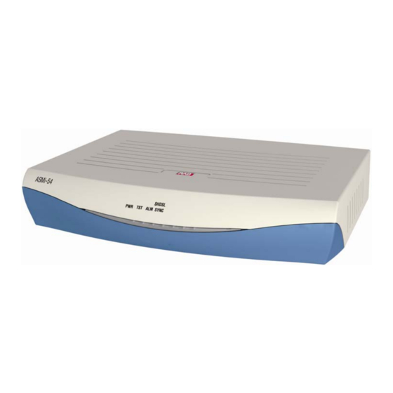
- Page 21 Installation and Operation Manual Chapter 1 Introduction Physical Description ASMi-54 is a 1U high standalone device in a plastic or metal enclosure. Figure shows a three-dimensional view of the ASMi-54 unit with Ethernet Chapter 3. and SHDSL interfaces. The front and rear panels are shown in Figure 1-2.
- Page 22 Chapter 1 Introduction Installation and Operation Manual Ethernet Access (Bridge) ASMi-54 has a multi-port bridging capability handling up to six bridge ports. The Bridge supports two modes of operation: • VLAN-Aware • VLAN-Unaware. The mechanism of each mode can be described as five different processes: •...
- Page 23 Installation and Operation Manual Chapter 1 Introduction Enable: Performs ingress filtering according to VIDs. Only frames that share a VID assigned to this bridge port are admitted Disable: All frames are forwarded. Only admitted frames that pass filtering are submitted to learning and forwarding processes.
- Page 24 Chapter 1 Introduction Installation and Operation Manual The ASMi-54 VLAN-Aware bridge is an Independent VLAN Learning (IVL) bridge. The learning process inserts a new dynamic entry into the MAC table. This entry consists of a MAC-VID pair and bridge port. •...
- Page 25 Installation and Operation Manual Chapter 1 Introduction The frame format can be configured for each VLAN and port: • VLAN-tagged: In this mode: VLAN-tagged frames are transmitted unchanged. Untagged frames are transmitted tagged with priority according to the default priority of the ingress bridge port, and VID=PVID of the port from which they entered.
- Page 26 Chapter 1 Introduction Installation and Operation Manual entry entered the bridge. The periodic check of the MAC table (aging time intervals), results in an actual aging time that can reach up to twice the value that was configured by the user. Forwarding Process The forwarding process is performed based on the frame MAC Destination Address (MDA).
- Page 27 Chapter 3 Management Access The unit’s architecture allows access from every bridge port to both the host and remote site devices. In certain configuration modes, a total separation of management traffic from user traffic can be achieved.
- Page 28 Chapter 1 Introduction Installation and Operation Manual Security ASCII terminal, Telnet, and Web access are password protected. After a period of 15 minutes of inactivity, the system exits to the password screen. ASMi-54 supports the following access authorization levels: •...
- Page 29 Installation and Operation Manual Chapter 1 Introduction • 1536 kpbs – 5.7 km (26 AWG, noise free) • 2048 kpbs – 5.1 km • 4096 kpbs – 3.9 km • 4608 kpbs – 3.5 km • 5696 kpbs – 2.9 km. *Preliminary estimate Impedance 135Ω...
- Page 30 Chapter 1 Introduction Installation and Operation Manual Timing Derived from alternative sources: • Internal oscillator (only CO unit) • Receive, derived from the SHDSL received signal (only CPE unit) Diagnostics Statistics and SHDSL performance Performance Monitoring Indicators PWR (green) On: ASMi-54 is powered on (Front Panel) Off: ASMi-54 is off TST (yellow)
- Page 31 Installation and Operation Manual Chapter 1 Introduction Physical Plastic Enclosure Height 43.7 mm (1.7 in) Width 217 mm (8.5 in) Depth 170 mm (6.7 in) Weight 0.5 kg (1.1 lb) Metal Enclosure Height 43.7 mm (1.7 in) Width 217 mm (8.5 in) Depth 170 mm (6.7 in) Weight...
- Page 32 Chapter 1 Introduction Installation and Operation Manual 1-16 Technical Specifications ASMi-54 Ver. 1.0...
- Page 33 DC-powered ASMi-54 units require a -48 VDC power source, which must be adequately isolated from the main supply. Allow at least 90 cm (36 in) of frontal clearance for operator access. For continuous product operation allow at least 10 cm of frontal clearance and at least 15 cm at rear of the unit, for cable connections and ventilation.
- Page 34 Chapter 2 Installation and Setup Installation and Operation Manual The ambient operating temperature is 0º–50ºC (32º–122ºF), at a relative humidity of up to 90%, non-condensing. Package Contents The package contains the following items: • One ASMi-54 unit • AC power cord or DC adaptor connector •...
- Page 35 Installation and Operation Manual Chapter 2 Installation and Setup Mounting the Unit Rack Mounting Kit For mounting the ASMi-54 unit in a 19-inch rack, refer to the for 19-inch Racks guide that comes with the RM-33-2 kit. Connecting the Cables Figure 2-1 - Figure 2-3 show the options for the rear panel of an AC/DC powered ASMi-54 unit.
- Page 36 Chapter 2 Installation and Setup Installation and Operation Manual Connecting to the SHDSL Equipment The SHDSL interfaces terminate in an 8-pin RJ-45 connector. To connect the SHDSL interface: • Connect an SHDSL line to an RJ-45 connector designated SHDSL (1,2,3,4). Connecting to an ASCII Terminal To connect the ASCII terminal: •...
- Page 37 Chapter 3 Operation This chapter provides the following information for ASMi-54: • Explains power-on and power-off procedures • Provides a detailed description of the controls and indicators and their functions • Provides instructions for using a terminal connected to the ASMi-54 control port •...
- Page 38 Chapter 3 Operation Installation and Operation Manual Figure 3-1. ASMi-54 Front Panel (Plastic Enclosure) Figure 3-2. ASMi-54 Front Panel (Metal Enclosure) Table 3-1. ASMi-54 Front Panel LEDs Name Color Function Green On: ASMi-54 is powered on Off: ASMi-54 is off On: A test is active Off: A test is inactive On: Alarm is active...
- Page 39 Installation and Operation Manual Chapter 3 Operation Figure 3-3. ASMi-54 with One SHDSL Port and One Ethernet Port Figure 3-4. ASMi-54 with One SHDSL Port and Four Ethernet Ports Figure 3-5. ASMi-54 with Two SHDSL Ports and Four Ethernet Ports Table 3-2.
- Page 40 Host Tagging Untagged Host VLAN ID Host Priority Tag Management User Name USER ; SU Access Old Password 1234 User Access New Password Empty string User Level Confirm New Password Empty string Telnet Access Enable SNMP Access Enable Web Access...
- Page 41 Installation and Operation Manual Chapter 3 Operation Table 3-5. Default SHDSL Settings Menu Parameter Default Value SHDSL PCS (Physical Coding Sublayer) Administrative Status Power Backoff Disable Clock Source RX Clock: STU-R PME (Physical Medium Entity) Configuration Administrative Status Line Probe Disable Current Margin 0 dB [Disable]...
- Page 42 Chapter 3 Operation Installation and Operation Manual Table 3-8. Default QoS Settings Menu Parameter Default Value Priority Classification 802.1p Priority Mapping User Priority 0 Traffic Class 0 User Priority 1 Traffic Class 0 User Priority 2 Traffic Class 0 User Priority 3 Traffic Class 0 User Priority 4 Traffic Class 0...
- Page 43 To log in: 1. Enter su for user name with read/write permission. 2. Enter 1234 for (default) password. Note It is recommended to change default passwords to prevent unauthorized access to the unit. Choosing Options To choose an option: 1. Press the number corresponding to the option, and press <Enter>.
- Page 44 Chapter 3 Operation Installation and Operation Manual Navigating Tables Some of the management screens, such as the Manager table, are tables that are larger than regular menus and may require scrolling to navigate between parameters. These screens are best viewed when your terminal screen is set to 132 character width.
- Page 45 Web Browser Requirements The following Web browsers can be used to access the ASMi-54 ConfiguRAD supervision utility from any location using Internet protocols. • Internet Explorer version 6.0 and up, running on Windows™ 98, Windows™...
- Page 46 The ConfiguRAD Main menu is displayed. • Note It is recommended to change default passwords to prevent unauthorized access to the unit. • ASMi-54 allows six management sessions to be active simultaneously: one network session (Telnet, ConfiguRAD, RADview-Lite) and one ASCII terminal session.
- Page 47 Installation and Operation Manual Chapter 3 Operation Figure 3-10. Configuration Menu Map – Page 2 ASMi-54 Ver. 1.0 Configuration and Management Alternatives 3-11...
- Page 48 Chapter 3 Operation Installation and Operation Manual Figure 3-11. Monitoring Menu Map – Page 3 3-12 Configuration and Management Alternatives ASMi-54 Ver. 1.0...
- Page 49 Installation and Operation Manual Chapter 3 Operation Turning Off the Unit To power off the ASMi-54 unit: • Remove the power cord from the power source. ASMi-54 Ver. 1.0 Turning Off the Unit 3-13...
- Page 50 Chapter 3 Operation Installation and Operation Manual 3-14 Turning Off the Unit ASMi-54 Ver. 1.0...
-
Page 51: Entering Device Information
Chapter 4 Configuration This chapter describes how to configure the ASMi-54 for management and operational tasks. Configuration screens are shown, and configuration parameters explained. Note The configuration screens illustrated in this chapter are taken from a terminal screen, but most of the menus are similar to those viewed in Telnet and ConfiguRAD. - Page 52 Figure 4-2. Configuration System Screen ASMi-54 Main Menu > Configuration >System > Management 1. Device information > 2. Host > 3. Managers list [] > 4. Management Access > ESC-Previous menu; !-Main menu; &-Exit Figure 4-3. Management Screen Configuring for Management ASMi-54 Ver. 1.0...
-
Page 53: Configuring Ip Host Parameters
Installation and Operation Manual Chapter 4 Configuration ASMi-54 Main Menu > Configuration > System > Management > Device Information Description … (ASMi-54, HW Version 0.00, SW Version 1.00) 1. Name … (ASMi-54) 2. Location … (Location of the device) 3. Contact …... - Page 54 Chapter 4 Configuration Installation and Operation Manual Tagged – The host receives frames only when they are tagged with the host’s VLAN ID, and it sends frames to the bridge with this tag. Note When Host Tagging is set to Tagged, two parameters are added to the menu: Host VLAN ID and VLAN Priority.
-
Page 55: Configuring Terminal Parameters
Installation and Operation Manual Chapter 4 Configuration Configuring Terminal Parameters The Terminal is connected to the Control Port. The management software allows you to configure the terminal baud rate. Note The Baud Rate parameter is masked during a Telnet session. To change the terminal baud rate: 1. -
Page 56: Setting Management Access
2. Select Management Access. The Management Access screen appears (see Figure 4-9 3. Select the access level you wish to change: Telnet Access, SNMP Access, or WEB Access. 4. Select the permission setting for this access level: Enable, Disable or Manage Only. - Page 57 Installation and Operation Manual Chapter 4 Configuration 5. Select Change Cell, and press <Enter> to enter a new IP address for the selected network manager. 6. Move the cursor to the Trap field and toggle between Mask and Unmask to mask or unmask traps for the selected management station.
-
Page 58: Configuring For Operation
Chapter 4 Configuration Installation and Operation Manual Configuring for Operation This section explains how to operate the unit. Setting Device-Level Parameters This section includes procedures for setting the configuring fault propagation options. Configuring Fault Propagation When the Network > User Fault Propagation feature is enabled, the LAN ports are deactivated when the PCS uplink goes down. -
Page 59: Configuring Physical-Level Port Parameters
Installation and Operation Manual Chapter 4 Configuration To configure the NTP client parameters: 1. Select Main Menu>Configuration>System. Figure 4-2 The Configuration System screen appears (see 2. Select Date and Time. Figure 4-13 The Date and Time screen appears (see ). The parameters are Table 4-1 described in 3. - Page 60 Chapter 4 Configuration Installation and Operation Manual Configuring the Fast Ethernet Port The following parameters can be configured for the Ethernet ports at the physical level: • Administrative Status • Autonegotiation • Flow Control • Maximum advertised capability for autonegotiation procedure •...
- Page 61 Installation and Operation Manual Chapter 4 Configuration ASMi-54 Main Menu > Configuration > Physical Layer > Ethernet Port 1. Administrative Status (Up) 2. Auto Negotiation (Enable) 3. Flow Control (Disable) 4. Max Capability Advertised (100base – TX Full Duplex) 5. MDIX Auto Cross Over (Enable) F-Forwards;...
- Page 62 Chapter 4 Configuration Installation and Operation Manual Configuring the SHDSL Ports This section includes procedures for configuring the SHDSL PCS ports, configuring the SHDSL PME ports, and setting the clock source. Configuring the SHDSL PCS Ports To configure SHDSL PCS ports: 1.
- Page 63 Installation and Operation Manual Chapter 4 Configuration Parameter Possible Values Remarks Transmission Annex A/F The regional setting of the SHDSL span. Mode Annex B/G Default: Annex B/G Note: This parameter can be configured in STU-C mode only. The configuration of the PME (Physical Medium Entity), Configuring the SHDSL PME Ports Configuration Configuring the Clock Source...
- Page 64 Chapter 4 Configuration Installation and Operation Manual ASMi-54 Main Menu > Configuration > Physical Layer > SHDSL > PME Configuration PME (Physical Medium Entity) 1. Administrative Status (Up) 2. Line Probe (Disable) 3. Line Rate (192000) 4. Current Margin > (0) 5.
- Page 65 Installation and Operation Manual Chapter 4 Configuration Parameter Possible Values Remarks SNR Margin 0…15 The SNR margin alarm threshold. Threshold (dB) Default: 0 Configuring the SHDSL PME Current Margin Only available in STU-R mode. Note To configure the SHDSL PME current margin: 1.
- Page 66 Chapter 4 Configuration Installation and Operation Manual ASMi-54 Main Menu > Configuration > Physical Layer > SHDSL > PME Configuration > Current Margin 1. –10 dB 17. 6 dB 2. –9 dB 18. 7 dB 3. –8 dB 19. 8 dB 4.
- Page 67 Installation and Operation Manual Chapter 4 Configuration Configuring 6. For VLAN Membership configuration (in Aware bridge only), see VLAN Membership 7. Press <S> to save the changes. ASMi-54 Main Menu > Configuration > Applications 1. Bridge > 2. QoS > ESC-Previous menu;...
- Page 68 Chapter 4 Configuration Installation and Operation Manual Using the Static MAC Table Static MAC addresses are stored in the MAC table. To add a static MAC address: 1. Select Main Menu>Configuration>Applications> Bridge. Figure 4-20 The Bridge screen appears (see 2. Select Static MAC Table. Figure 4-21 The Static MAC Table screen appears (see ), with VLAN ID...
- Page 69 Installation and Operation Manual Chapter 4 Configuration ASMi-54 MAC table handling 1. MAC address … (00-00-00-00-00-00) 2. VLAN ID [1-4094] 3. Bridge port [1 – N] S - Save ESC-Previous menu; !-Main menu; &-Exit; ?-Help Figure 4-22. Static MAC Table, Add Mode To remove a static address from the table: 1.
- Page 70 Chapter 4 Configuration Installation and Operation Manual To delete a factory-set bridge port configuration: 1. Select Main Menu>Configuration>Applications>Bridge. Figure 4-20 The Bridge screen appears (see 2. Select Bridge Port. Figure 4-23 The Bridge Ports screen appears (see 3. Type the Bridge Port number. Note Bridge Port 1 is reserved for management.
- Page 71 Installation and Operation Manual Chapter 4 Configuration Table 4-7. Bridge Port Parameters Parameter Possible Values Remarks Bridge Port 1 - 6 Bridge port number. Number Default: 2 Note: Bridge port number 1 is reserved for the host bridge port. The type of port to be bound. To configure a bridge port, see Bind Configuring a Bridge Port Activation...
- Page 72 Chapter 4 Configuration Installation and Operation Manual Configuring a Bridge Port To configure a bridge port: 1. Select Main Menu>Configuration>Applications>Bridge>Bridge Ports. The Bridge Ports screen appears (see Figure 4-23 2. Select Bind to define which port the bridge port should be bound to. Figure 4-24 The Bind screen appears (see Note...
- Page 73 Installation and Operation Manual Chapter 4 Configuration 5. Select Egress Untagged Ports. Define the set of ports to transmit packets for this VLAN as untagged. 6. Press <A> to add BP to this VLAN. 7. Press <F> to toggle through the VLAN IDs. 8.
- Page 74 Chapter 4 Configuration Installation and Operation Manual 802.1p DSCP Per Port. 5. Press <S> to save the changes. ASMi-54 Main Menu > Configuration > Applications > QoS 1. Priority Classification (802.1p) 2. Priority Mapping > ESC-Previous menu; !-Main menu; &-Exit Figure 4-26.
- Page 75 Installation and Operation Manual Chapter 4 Configuration ASMi-54 Main Menu > Configuration > Applications > QoS > Priority Mapping (802.1p) 1. User Priority 0 > (Traffic Class 0) 2. User Priority 1 > (Traffic Class 0) 3. User Priority 2 > (Traffic Class 1) 4.
- Page 76 Chapter 4 Configuration Installation and Operation Manual ASMi-54 Main Menu > Configuration > Applications > QoS > Priority Mapping (DSCP) 1. Tag Value 0 > (Traffic Class 0) 2. Tag Value 1 > (Traffic Class 0) 3. Tag Value 2 > (Traffic Class 0) 4.
-
Page 77: Additional Tasks
Installation and Operation Manual Chapter 4 Configuration Additional Tasks Procedures for miscellaneous tasks are provided in this section. • Displaying the Inventory • Changing User Name and Password • Transferring Software and Configuration Files • Resetting ASMi-54. Displaying the Inventory The inventory displays a description of the unit, including its hardware revision and power supply type. -
Page 78: Changing User Name And Password
Reassign the new password. 8. Press <S> to save the changes. The new password is saved. ASMi-54 Main Menu > Configuration > System > Management > Management Access > User Access 1. Change password > ESC-Previous menu; !-Main menu; &-Exit Figure 4-32. -
Page 79: Transferring Software And Configuration Files
Installation and Operation Manual Chapter 4 Configuration ASMi-54 Main Menu > Configuration > System > Management > Management Access > User Access > User Level 1. User name … (USER) 2. Old Password … (********) 3. New password … (********) 4. - Page 80 Chapter 4 Configuration Installation and Operation Manual 6. Select File Type, and choose whether you intend to transfer a software program (IMG) or configuration file. 7. Select Save to save the changes. 8. Select Command to start the desired procedure: Upload: To save a software or configuration file on a remote server Download: To transfer a software or configuration file to the unit.
-
Page 81: Resetting Asmi-54
Installation and Operation Manual Chapter 4 Configuration ASMi-54 Main Menu > Utilities > File Transfer > TFTP Status (No operation) Error (No error) 1. Server IP Address (0.0.0.0) 2. Remote File name 3. File Type (Configuration) 4. Command > ESC-Previous menu; !-Main menu; &-Exit; ?-Help Figure 4-36. - Page 82 Chapter 4 Configuration Installation and Operation Manual Resetting the Unit You can perform an overall reset of the unit. To reset ASMi-54: 1. Select Main Menu>Utilities. The Utilities screen appears (see Figure 4-34 2. Select Reset Device. The following confirmation message appears: The device will restart.
-
Page 83: Chapter 5. Configuring Typical Applications
Chapter 5 Configuring Typical Applications This chapter gives detailed instructions for configuring for a typical application in which a unit is used for Customer Premises with inband management and an Aware Bridge. Configuring the ASMi-54 Application Figure 5-1 illustrates a typical application that includes Ethernet services, point- to-point. -
Page 84: Defining The Host
Chapter 5 Configuring Typical Applications Installation and Operation Manual Defining the Host Defines the host parameters such as IP address and subnet mask, and the read/write communities. To define the host: 1. From the Management menu (Main>Configuration>System>Management), select Host IP. The Host IP menu appears. -
Page 85: Configuring Shdsl Physical Layer
Installation and Operation Manual Chapter 5 Configuring Typical Applications 4. In the Trap field, specify Mask or Unmask to mask or unmask traps for the new management station. 5. Select Save. 6. Repeat the previous steps for each network manager you wish to add. To update existing manager parameters: 1. -
Page 86: Defining The Bridge
Chapter 5 Configuring Typical Applications Installation and Operation Manual Defining the Bridge Defines the Bridge entity. To define the bridge: 1. Open the Bridge menu (Main>Configuration>Application>Bridge). Configuring the Internal Bridge 2. Define the bridge parameters. See for more information on each of the parameters. Defining VLANs Define the required VLAN and add to it the relevant bridge ports. -
Page 87: Chapter 6. Diagnostics And Troubleshooting
• Troubleshoot the device • Perform connectivity tests. Monitoring Performance The software provides access to the following status information: • System level – MAC address, connection status, and Event Log file • Physical level – Ethernet and SHDSL port status •... - Page 88 Chapter 6 Diagnostics and Troubleshooting Installation and Operation Manual ASMi-54 Main Menu > Monitoring 1. System > 2. Physical Ports > 3. Application > C-Clear All Statistics ESC-Previous menu; !-Main menu; &-Exit; ?-Help Figure 6-1. Monitoring Screen ASMi-54 Main Menu > Monitoring > System MAC address …...
-
Page 89: Displaying The Physical Port Status
Installation and Operation Manual Chapter 6 Diagnostics and Troubleshooting Displaying the Physical Port Status You can view the status of the unit’s physical ports. Displaying For a description of the Ethernet and SHDSL port statistics, refer to Interface Statistics Displaying the Ethernet Port Status To display the Ethernet port status: 1. - Page 90 Chapter 6 Diagnostics and Troubleshooting Installation and Operation Manual ASMi-54 Main Menu > Monitoring > Physical Ports > Ethernet > Status Port Administrative Status (Enable) Operation Status (Up) Speed & Duplex (100Mbps – Full Duplex) Flow Control (Enable) F - Forwards; B - Backwards ESC-Previous menu;...
- Page 91 Installation and Operation Manual Chapter 6 Diagnostics and Troubleshooting ASMi-54 Main Menu > Monitoring > Physical Ports > SHDSL 1. Status > 2. Statistics > ESC-Previous menu; !-Main Menu; &-Exit Figure 6-7. Monitoring Physical Ports - SHDSL Screen ASMi-54 Main Menu > Monitoring > Physical Ports > SHDSL > Status PCS (Physical Coding Sublayer) (1) Administrative Status (Up)
- Page 92 Chapter 6 Diagnostics and Troubleshooting Installation and Operation Manual Displaying the SHDSL PME Port Status To display the SHDSL PME port status: 1. Select Main Menu>Monitoring>Physical Ports>SHDSL>Status. Figure 6-8 The SHDSL PCS Status screen appears (see 2. Select PME Status. Figure 6-9 The SHDSL PMS Status screen appears (see ).
-
Page 93: Displaying Application-Level Status
Installation and Operation Manual Chapter 6 Diagnostics and Troubleshooting Displaying Application-Level Status At the application level, the unit provides information of the MAC addresses (static and learned) and their bridge port assignments; as well as VLAN IDs and their bridge port assignments. To display the MAC table: 1. -
Page 94: Displaying Interface Statistics
Chapter 6 Diagnostics and Troubleshooting Installation and Operation Manual ASMi-54 Main Menu > Monitoring > Application > Bridge > View MAC Table MAC address Bridge port Status 11-11-11-11-11-11 Static 22-22-22-22-22-22 Dynamic 33-33-33-33-33-33 Static 44-44-44-44-44-44 Dynamic 55-55-55-55-55-55 Dynamic ESC-Previous menu; !-Main menu; &-Exit; ?-Help Figure 6-13. - Page 95 Installation and Operation Manual Chapter 6 Diagnostics and Troubleshooting 4. Press <F> to select the Port number. ASMi-54 Main Menu > Monitoring > Physical Ports> Ethernet > Statistics Port Rx Correct Frames (166185) Rx Correct Octets 10635840) Rx Alignment Error Rx FCS Errors Rx Congestion Dropped Frames Tx Correct Frames...
-
Page 96: Clearing Ethernet Port Statistics
Chapter 6 Diagnostics and Troubleshooting Installation and Operation Manual Parameter Description Tx Deferred Transmissions The number of transmission attempts deferred in order to avoid a collision. Tx Late Collisions The number of transmission attempts that experienced late collisions. Tx Congestion Dropped The number of frames discarded due to a lack of buffer Frames space. - Page 97 Installation and Operation Manual Chapter 6 Diagnostics and Troubleshooting ASMi-54 Main Menu > Monitoring > Physical Ports > SHDSL > Statistics PCS Number RX Total Frames RX Total Errors TX Total Frames 1. PME Statistics > 2. Clear All SHDSL Statistics F-Forwards ;...
- Page 98 Chapter 6 Diagnostics and Troubleshooting Installation and Operation Manual ASMi-54 Main Menu > Monitoring > Physical Ports > SHDSL > Statistics > PME Statistics PME (Physical Medium Entity) Number PCS (Physical Coding Sublayer) Number 1. Current Interval 2. 15 Min. Intervals 3.
- Page 99 Installation and Operation Manual Chapter 6 Diagnostics and Troubleshooting ASMi-54 Main Menu > Monitoring > Physical Ports > SHDSL > Statistics > PME Statistics > Current Interval PME (Physical Medium Entity) Number PCS (Physical Coding Sublayer) Number LOSWS CRC Anomalies Elapsed Time (150) F-Forwards ;...
- Page 100 Chapter 6 Diagnostics and Troubleshooting Installation and Operation Manual Displaying SHDSL PME 15 Minute Intervals Statistics To view SHDSL PME 15 minute intervals statistics: 1. Select Main Menu>Monitoring>Physical Ports>SHDSL>Statistics >PME Statistics. The SHDSL PME Statistics screen appears (see Figure 6-16 2.
- Page 101 Installation and Operation Manual Chapter 6 Diagnostics and Troubleshooting Parameter Description LOSWS The number of Loss of Sync Word (LOSW) Seconds during the interval. CRC Anomalies The number of CRC anomalies during the interval. Displaying SHDSL PME Current Interval StatisticsTo view SHDSL PME Current Interval statistics: 1.
- Page 102 Chapter 6 Diagnostics and Troubleshooting Installation and Operation Manual Parameter Description The number of Severely Errored Seconds (ES) during the current day. LOSWS The number of Loss of Sync Word (LOSW) Seconds during the current day. CRC Anomalies The number of CRC anomalies during the current day. Elapsed Time The number of seconds that have elapsed since the beginning of the current 1-day interval.
- Page 103 Installation and Operation Manual Chapter 6 Diagnostics and Troubleshooting Table 6-12. SHDSL PME Day Intervals Statistics Parameter Description PME (Physical Medium The selected SHDSL PME number. Entity) Number PCS (Physical Coding The SHDSL PCS number to which the PME line belongs. Sublayer) Number Interval Number The History Data Interval number.
-
Page 104: Clearing The Shdsl Port Statistics
Chapter 6 Diagnostics and Troubleshooting Installation and Operation Manual Table 6-13. SHDSL PME Accumulated Data Statistics Parameter Description The number of Errored Seconds (ES) on this endpoint since it was last restarted. The number of Unavailable Seconds (UAS) on this endpoint since it was last restarted. -
Page 105: Displaying The Event Log File
00-00-0000 and system uptime. Once the NTP server becomes available, all messages (including those already received) appear with the real date and time. To access the Event Log file: 1. Select Main Menu>Monitoring>System. Figure 6-1 The Monitoring screen appears (see 2. - Page 106 Chapter 6 Diagnostics and Troubleshooting Installation and Operation Manual ASMi-54 Main Menu > Monitoring > System > Event Log Source Description Information Severity Date Time PME Port 1 LINK_DOWN PME port Major 04-07-1776 00:00:01 PME Port 2 LINK_UP PME port Major 02-06-1946 00:00:02...
-
Page 107: Clearing The Event Log File
Installation and Operation Manual Chapter 6 Diagnostics and Troubleshooting Trap Description trap, the snmpEnableAuthenTraps object indicates whether this trap will be generated. TFTP Status This trap is sent whenever the status of TFTP changed. Status Change This trap is sent whenever the state of the entity the agent is responsible for changed. -
Page 108: Troubleshooting
Chapter 6 Diagnostics and Troubleshooting Installation and Operation Manual Troubleshooting Table 6-16 Use the chart shown in to identify and remedy problems in unit operation. Table 6-16. Troubleshooting Chart Fault Probable Cause Remedial Action • Power led off No power supplied to unit Check power source. -
Page 109: Testing The Unit
Installation and Operation Manual Chapter 6 Diagnostics and Troubleshooting Testing the Unit ASMi-54 checks network integrity by running ping, trace route, or loopback tests. Running a Ping Test You can ping the remote IP host to check the IP connectivity. To ping an IP host: 1. -
Page 110: Tracing The Route
Chapter 6 Diagnostics and Troubleshooting Installation and Operation Manual Tracing the Route This diagnostic utility traces the route through the network from ASMi-54 to the destination host. To trace a route: 1. Select Main Menu>Diagnostics. Figure 6-24 The Diagnostics menu appears (see 2. -
Page 111: Appendix A Pinouts
Appendix A Pinouts Ethernet Connector The 10/100BaseT Ethernet electrical interface is an 8-pin RJ-45 connector, wired Table A-1 in accordance with Table A-1. 10/100BaseT Ethernet Connector Pinouts Function Tx– 4, 5 – Rx– 7, 8 – SHDSL Connector The SHDSL electrical interface is an 8-pin RJ-45 connector, wired in accordance Table A-2 with Table A-2. - Page 112 Appendix A Pinouts Installation and Operation Manual Control Connector The control terminal interface terminates in a V.24/RS-232 9-pin D-type female Table A-3 DCE connector. lists the control connector pin assignments. Table A-3. CONTROL Connector Pinout Function Txd (TD) Rxd (RD) Ground (GND) Control Connector ASMi-54 Ver.
-
Page 113: Appendix B Boot Sequence And Downloading Software
Booting ASMi-54 ASMi-54 boots up automatically. After powering up, no user intervention is required, except when the user wants to access the file system to modify or update the software or the ASMi-54 configuration. Accessing the Boot Manager The Boot Manager menu is an option that allows the user to perform basic file transfer operations. - Page 114 Appendix B Boot Sequence and Downloading Software Installation and Operation Manual ASMi-54 Boot Version 1.00 (Jan 20 2005) Boot manager version 7.02 (Jan 20 2005) 0 - Exit Boot-Manager 1 - Dir 2 - Set Active Software Copy 3 - Delete Software Copy 4 - Download an Application by XMODEM 5 - Format flash 6 - Show basic hardware information...
- Page 115 To download application file via XMODEM: 1. Configure your ASCII terminal or terminal emulation utility running on your PC to the 115.2 kbps data rate. 2. Access the Boot Manager menu. Figure B-1 The Boot Manager menu appears (see 3. From the Boot Manager menu, select Download Files or an Application by XMODEM.
- Page 116 Appendix B Boot Sequence and Downloading Software Installation and Operation Manual ASMi-54 automatically erases the backup partition (it takes about 25 seconds). Once the downloading is completed, ASMi-54 saves the new release as an active partition; the former active partition becomes a backup. Transferring the Software and Configuration Files ASMi-54 Ver.
- Page 117 —A— Host, AC Power, Internal bridge, 4-16 Additional tasks, 4-27 IP host parameters, Aging, Management, Aging Process management access, VLAN-Aware bridge, Managers, VLAN–Unaware bridge, 1-10 network managers, Application ports, configuring, QoS priorities, 4-23 Application-level status SHDSL PCS ports,...
- Page 118 Index Installation and Operation Manual power cable, WAN, Equipment for installation, Internal bridge, 4-16 Ethernet. See Fast Ethernet Internal clock access, source, 4-13 Ethernet in the First Mile. See EFM Inventory, 4-27 Ethernet interface, pinouts, —L— Ethernet port statistics Learning,...
- Page 119 Installation and Operation Manual Index Ping, 6-23 new releases, 4-29 Pinouts, updates, 4-29, PME, 1-3, 6-11 versions, 4-29 Power source, 1-14 Specifications Powering bridge, 1-13 down, 3-13 Statistics, 1-4, 1-12, System messages, 6-18 Prerequisites, PVID assignment, —T— Technical specifications, 1-12 —Q—...
- Page 120 Index Installation and Operation Manual ASMi-54 Ver. 1.0...
- Page 121 24 Raoul Wallenberg Street, Tel Aviv 69719, Israel Tel: +972-3-6458181, Fax +972-3-6483331, +972-3-6498250 E-mail: erika_y@rad.com, Web site: http://www.rad.com Customer Response Form RAD Data Communications would like your help in improving its product documentation. Please complete and return this form by mail or by fax or send us an e-mail with your comments.
- Page 123 Error Report Type of error(s) or Incompatibility with product problem(s): Difficulty in understanding text Regulatory information (Safety, Compliance, Warnings, etc.) Difficulty in finding needed information Missing information Illogical flow of information Style (spelling, grammar, references, etc.) Appearance Other Please list the exact page numbers with the error(s), detail the errors you found (information missing, unclear or inadequately explained, etc.) and attach the page to your fax, if necessary.
- Page 126 International Headquarters 24 Raoul Wallenberg Street Tel Aviv 69719, Israel Tel. 972-3-6458181 Fax 972-3-6498250, 6474436 E-mail market@rad.com North America Headquarters 900 Corporate Drive Mahwah, NJ 07430, USA Tel. 201-5291100 Toll free 1-800-4447234 Fax 201-5295777 E-mail market@radusa.com www.rad.com The Access Company...
Need help?
Do you have a question about the RAD ASMi-54 and is the answer not in the manual?
Questions and answers