Table of Contents
Advertisement
Quick Links
Advertisement
Table of Contents

Related Manuals for Oracle SPARC T8-1


Summary of Contents for Oracle SPARC T8-1
- Page 1 SPARC T8-1 Server Service Manual Part No: E80510-04 January 2022...
- Page 3 Oracle. Oracle Corporation and its affiliates will not be responsible for any loss, costs, or damages incurred due to your access to or use of third-party content, products, or services, except as set forth in an applicable agreement between you and Oracle.
- Page 4 Oracle Corporation et ses affiliés déclinent toute responsabilité ou garantie expresse quant aux contenus, produits ou services émanant de tiers, sauf mention contraire stipulée dans un contrat entre vous et Oracle. En aucun cas, Oracle Corporation et ses affiliés ne sauraient être tenus pour responsables des pertes subies, des coûts occasionnés ou des dommages causés par l'accès à...
-
Page 5: Table Of Contents
▼ Check the Message Buffer .............. 32 ▼ View Log Files (Oracle Solaris) ............ 33 ▼ View Log Files (Oracle ILOM) ............ 33 POST Overview .................. 34 ▼ Configure POST ................ 34 Oracle ILOM Properties That Affect POST Behavior ........ 36 ▼ Clear a Fault Manually ................ 37... - Page 6 ▼ Remove a Drive or Drive Filler .............. 61 ▼ Install a Drive or Drive Filler .............. 65 ▼ Verify a Drive .................. 66 Servicing Fan Modules .................. 69 Fan Module LEDs .................. 70 ▼ Determine Which Fan Module Is Faulty ............ 71 SPARC T8-1 Server Service Manual • January 2022...
- Page 7 Memory Riser and DIMM FRU Names ............. 85 ▼ Add Memory to the Server ................ 87 ▼ Replace a Faulty DIMM ................ 88 ▼ Locate a Faulty DIMM (Oracle ILOM) ............ 89 ▼ Locate a Faulty DIMM (Fault Remind Button) .......... 90 ▼ Remove a Memory Riser ................ 91 ▼...
- Page 8 ▼ Return the Server to the Normal Operating Position ........ 158 ▼ Attach Power Cords ................ 159 ▼ Power On the Server (Oracle ILOM) ............ 159 ▼ Power On the Server (System Power Button) .......... 160 Glossary ...................... 161 Index ........................ 165 SPARC T8-1 Server Service Manual • January 2022...
-
Page 9: Using This Documentation
Product Documentation Library Documentation and resources for this product and related products are available at http://www. oracle.com/goto/t8-1/docs. Feedback Provide feedback about this documentation at http://www.oracle.com/goto/docfeedback. Using This Documentation... - Page 10 SPARC T8-1 Server Service Manual • January 2022...
-
Page 11: Identifying Components
Identifying Components These topics identify key components of the server, including major boards and internal system cables, as well as front and rear panel features. “Front Panel Components” on page 11 ■ “Rear Panel Components” on page 13 ■ “Internal Component Locations” on page 14 ■... - Page 12 “Servicing Drives” on page 59 HDD 5 or NVMe 3 “Servicing Drives” on page 59 HDD 6 or NVMe 4 “Servicing Drives” on page 59 HDD 7 “Servicing Drives” on page 59 SPARC T8-1 Server Service Manual • January 2022...
-
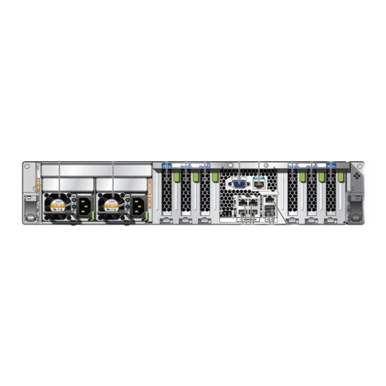
Page 13: Rear Panel Components
Rear Panel Components Related Information “Rear Panel Components” on page 13 ■ “Internal Component Locations” on page 14 ■ “Server Block Diagram” on page 17 ■ Rear Panel Components Description Links Power supply 0 “Servicing Power Supplies” on page 77 Power supply 1 “Servicing Power Supplies”... -
Page 14: Internal Component Locations
■ “Server Block Diagram” on page 17 ■ Internal Component Locations The following figure identifies the replaceable component locations with the top cover removed. The two memory risers are optional. Note - SPARC T8-1 Server Service Manual • January 2022... - Page 15 Internal Component Locations Component Oracle ILOM Target Links Drive cage (drive backplane on the rear of “Servicing the Drive /SYS/DBP the drive cage) Backplane” on page 147 Fan module cover “Remove the Fan Cover” on page 55 “Replace the Fan Cover” on page 154...
- Page 16 /SYS/DBP/HDD2 or /SYS/DBP/NVME0 /SYS/DBP/HDD3 or /SYS/DBP/NVME1 /SYS/DBP/HDD4 or /SYS/DBP/NVME2 /SYS/DBP/HDD5 or /SYS/DBP/NVME3 /SYS/DBP/HDD6 /SYS/DBP/HDD7 (right) Processor chip (replaceable only by “Servicing the /SYS/MB/CM/CMP replacing the motherboard) Motherboard” on page 129 eUSB drive /SYS/MB/EUSB_DISK SPARC T8-1 Server Service Manual • January 2022...
-
Page 17: Server Block Diagram
Server Block Diagram Related Information “Component Names Displayed by Diagnostic Software” on page 26 ■ “Front Panel Components” on page 11 ■ “Rear Panel Components” on page 13 ■ “Internal Component Locations” on page 14 ■ “Server Block Diagram” on page 17 ■... - Page 18 Device Path PCIe 1 /pci@300/pci@2 PCIe 2 /pci@303/pci@2 PCIe 3 /pci@303/pci@1 PCIe 4 /pci@302/pci@1 PCIe 5 /pci@302/pci@2 PCIe 6 /pci@301/pci@1 NET 0 /pci@300/pci@1/network@0 NET 1 /pci@300/pci@1/network@0,1 NET 2 /pci@300/pci@3/network@0 NET 3 /pci@300/pci@3/network@0,1 SPARC T8-1 Server Service Manual • January 2022...
- Page 19 Server Block Diagram Device Path HDD 0 /pci@301/pci@2/scsi@0/disk@p0 HDD 1 /pci@301/pci@2/scsi@0/disk@p1 HDD 2 /pci@301/pci@2/scsi@0/disk@p2 NVMe 0 /pci@303/pci@1/pci@0/pci@6/nvme@0/disk@1 HDD 3 /pci@301/pci@2/scsi@0/disk@p3 NVMe 1 /pci@303/pci@1/pci@0/pci@7/nvme@0/disk@1 HDD 4 /pci@301/pci@2/scsi@0/disk@p4 NVMe 2 /pci@303/pci@1/pci@0/pci@5/nvme@0/disk@1 HDD 5 /pci@301/pci@2/scsi@0/disk@p4 NVMe 3 /pci@303/pci@1/pci@0/pci@4/nvme@0/disk@1 HDD 6 /pci@301/pci@2/scsi@0/disk@p6 HDD 7 /pci@301/pci@2/scsi@0/disk@p7 Related Information “Component Names Displayed by Diagnostic Software”...
- Page 20 SPARC T8-1 Server Service Manual • January 2022...
-
Page 21: Detecting And Managing Faults
Use these tools to identify components that require service. Step Description Links “Log In to Oracle ILOM (Service)” on page 22 Run the fmadm faulty command to display information about components “Identify Faulted Components” on page 23 that require service. -
Page 22: Log In To Oracle Ilom (Service)
At the terminal prompt, type: ssh root@SP-IP-address Password: password Oracle (R) Integrated Lights Out Manager Version Version 4.0.x Copyright (c) 2017, Oracle and/or its affiliates, Inc. All rights reserved. -> Related Information “Identify Faulted Components” on page 23 ■ “Identify Disabled Components” on page 25 ■... -
Page 23: Identify Faulted Components
Identify Faulted Components The fmadm faulty command displays the list of faults detected by PSH (Predictive Self Healing). You can run this command from the host or through the Oracle ILOM fault management shell. From the Oracle ILOM prompt, start the fault management shell and type fmadm faulty. - Page 24 Obtain the message ID from console output (SPT-8000-PX in the example above). Go to https://support.oracle.com, and search on the message ID in the Knowledge tab, or type the URL from the Action field into a browser. Follow the suggested actions to repair the fault.
-
Page 25: Identify Disabled Components
Identify Disabled Components Identify Disabled Components You can run the show disabled command from the Oracle ILOM prompt to identify components that have been disabled either intentionally, by a user, or automatically, because of a fault. At the Oracle ILOM prompt, type: ->... -
Page 26: Component Names Displayed By Diagnostic Software
/SYS/MB/FM3 (right) Memory risers “Servicing Memory Risers and /SYS/MB/CM/CMP/MR0 DIMMs” on page 83 /SYS/MB/CM/CMP/MR1 Motherboard “Servicing the /SYS/MB Motherboard” on page 129 PCIe cards “Servicing PCIe /SYS/MB/PCIE1 Cards” on page 107 /SYS/MB/PCIE2 SPARC T8-1 Server Service Manual • January 2022... -
Page 27: Interpreting Leds
/SYS/PS0 (outer) Supplies” on page 77 /SYS/PS1 (inner) “Servicing the SPM” on page 121 /SYS/MB/SPM Related Information “Log In to Oracle ILOM (Service)” on page 22 ■ “Identify Faulted Components” on page 23 ■ “Identify Disabled Components” on page 25 ■... -
Page 28: Front Panel Controls And Leds
■ Slow blink – A normal but transitory activity is taking place. Slow blinking might indicate that server diagnostics are running or that the server is booting. ■ Standby blink – Server is running in standby mode and can be quickly returned to full function. SPARC T8-1 Server Service Manual • January 2022... - Page 29 ■ Steady on – SP is running in its normal operating state. No service actions are required. ■ Slow Blink – SP is initializing the Oracle ILOM firmware. Fan Module Fault LED (amber) Indicates these conditions: ■...
-
Page 30: Rear Panel Controls And Leds
■ Off – 12V DC output from this power supply is disabled or not within specification. ■ Steady on – 12V DC output from this power supply is present and within specifications. SPARC T8-1 Server Service Manual • January 2022... - Page 31 Interpreting LEDs Icon or Label Description Locate indicator and button Turn on the Locate indicator by pressing the Locator button, or see (white) “Locate the Server” on page 43. When lit, the LED blinks rapidly. The blinking will time out after 15 minutes. Service Required LED The fmadm faulty command provides details about any (amber)
-
Page 32: Performing Advanced Troubleshooting
Log in as an Oracle Solaris OS superuser. Type: # dmesg Related Information “View Log Files (Oracle Solaris)” on page 33 ■ “View Log Files (Oracle ILOM)” on page 33 ■ “POST Overview” on page 34 ■ SPARC T8-1 Server Service Manual • January 2022... -
Page 33: View Log Files (Oracle Solaris)
To view all logged messages, type: # more /var/adm/messages* Related Information “Check the Message Buffer” on page 32 ■ “View Log Files (Oracle Solaris)” on page 33 ■ “POST Overview” on page 34 ■ View Log Files (Oracle ILOM) View the event log. -
Page 34: Post Overview
You can also set other Oracle ILOM properties to control various other aspects of POST operations. For example, you can specify the events that cause POST to run, the level of testing POST performs, and the amount of diagnostic information POST displays. - Page 35 To set error_level, to max, and to set hw_change_level to max, type: -> set /HOST/diag error_level=max -> set /HOST/diag hw_change_level=max Refer to the section on setting the SPARC host keyswitch state in the Oracle ILOM Administrator’s Guide for Configuration and Maintenance Firmware Release 4.0.x for a description of parameters and values.
-
Page 36: Oracle Ilom Properties That Affect Post Behavior
Oracle ILOM Properties That Affect POST Behavior There are a number of Oracle ILOM commands that you can use to perform host diagnostic tests. For details about using these commands, refer to the chapter that describes configuring host server management actions in the Oracle ILOM Administrator's Guide for Configuration and Maintenance Firmware Release 4.0.x. -
Page 37: Clear A Fault Manually
Clear the fault in the Oracle Enterprise Manager Ops Center software, if applicable. Clearing a fault with the fmadm aquit command does not clear that fault in the Oracle Enterprise Manager Ops Center software. You must manually clear the fault or incident. For... - Page 38 Clear a Fault Manually more information, refer to the section on marking an incident repaired in the Oracle Enterprise Manager Ops Center Feature Reference Guide at: http://www.oracle.com/pls/topic/lookup?ctx=oc122 If you are servicing a component, return to the procedure for that component.
-
Page 39: Preparing For Service
Preparing for Service These topics describe how to prepare the server for servicing. Use only SPARC T8 components in SPARC T8 servers. Note - Step Description Links Review safety and handling information. “Safety Information” on page 39 Gather the tools needed for service. “Tools Needed For Service”... -
Page 40: Safety Symbols
Antistatic Wrist Strap Use Wear an antistatic wrist strap and use an antistatic mat when handling components such as drive assemblies, circuit boards, or PCIe cards. When servicing or removing server components, SPARC T8-1 Server Service Manual • January 2022... -
Page 41: Antistatic Mat
Tools Needed For Service attach an antistatic strap to your wrist and then to a metal area on the chassis. Following this practice equalizes the electrical potentials between you and the server. Note - An antistatic wrist strap is no longer included in the accessory kit for this server. However, antistatic wrist straps are still included with options. -
Page 42: Fillers
Read the serial number from a sticker located on the front of the server or ■ another sticker on the side of the server. At the Oracle ILOM prompt, type. ■ -> show /System SPARC T8-1 Server Service Manual • January 2022... -
Page 43: Locate The Server
30 minutes before turning off. After locating the server with the blinking Locate indicator, turn it off by pressing the Server Locator button. Alternatively, you can type an Oracle ILOM command to turn off the Locate indicator. -> set /System/locator_indicator=off Related Information “Front Panel Components”... - Page 44 PROM to new motherboard. personnel Drive backplane “Servicing the Drive Backplane” on page 147 LED indicator modules (front left and front right) Related Information “Internal Component Locations” on page 14 ■ SPARC T8-1 Server Service Manual • January 2022...
-
Page 45: Removing Power From The Server
Save any open files and quit all running programs. Refer to your application documentation for specific information on these processes. Shut down all LDoms. Refer to Oracle Solaris system administration and Oracle VM Server for SPARC documentation for additional information. Preparing for Service... -
Page 46: Power Off The Server (Oracle Ilom)
Prepare to power off the server. “Prepare to Power Off the Server” on page If you are consoled to the host, switch from the system console to the Oracle ILOM prompt by typing the #. (Hash-Dot) key sequence. Power off the server. -
Page 47: Power Off The Server (Server Power Button - Graceful)
You might need to use a pointed object, such as a pen or pencil. Related Information “Prepare to Power Off the Server” on page 45 ■ “Power Off the Server (Oracle ILOM)” on page 46 ■ “Power Off the Server (Emergency Shutdown)” on page 47 ■... -
Page 48: Disconnect Power Cords
Related Information “Safety Information” on page 39 ■ “Power Off the Server (Oracle ILOM)” on page 46 ■ “Power Off the Server (Server Power Button - Graceful)” on page 47 ■ “Power Off the Server (Emergency Shutdown)” on page 47 ■... -
Page 49: Prevent Esd Damage
Prevent ESD Damage Prevent ESD Damage Many components housed within the chassis can be damaged by ESD. To protect these components from damage, perform the following steps before opening the chassis for service. Prepare an antistatic surface to set parts on during the removal or installation process. - Page 50 While squeezing the slide release latches, slowly pull the server forward until the slide rails latch. Related Information “Release the CMA” on page 51 ■ “Remove the Server From the Rack” on page 52 ■ SPARC T8-1 Server Service Manual • January 2022...
-
Page 51: Release The Cma
For instructions on how to install the CMA for the first time, refer to “Prepare the CMA Note - for Installation” in SPARC T8-1 Server Installation Guide. Press and hold the tab. The tab is on the inside rear of the left side of the CMA. -
Page 52: Remove The Server From The Rack
From the front of the server, pull the release tabs forward and pull the server forward until it is free of the rack rails. A release tab is located on each rail. Set the server on a sturdy work surface. SPARC T8-1 Server Service Manual • January 2022... -
Page 53: Remove The Top Cover
Remove the Top Cover Related Information “Extend the Server to the Service Position” on page 49 ■ “Release the CMA” on page 51 ■ “Remove the Top Cover” on page 53 ■ Remove the Top Cover Removing the top cover without properly powering down the server and Caution - disconnecting the AC power cords from the power supplies results in a chassis intrusion switch failure. -
Page 54: Open And Remove The Airflow Cover
Lift the edge of the airflow cover closest to the rear of the server. The airflow cover can stand in its upright position. Perform the next steps if you need to remove the airflow cover. SPARC T8-1 Server Service Manual • January 2022... -
Page 55: Remove The Fan Cover
Remove the Fan Cover Open the fan cover. Pull open the plastic tabs to release the airflow cover's hinge edge from the server. Related Information “Install and Close the Airflow Cover” on page 155 ■ “Remove the Top Cover” on page 53 ■... - Page 56 Lift the fan cover from the server. Related Information “Replace the Fan Cover” on page 154 ■ “Open and Remove the Airflow Cover” on page 54 ■ “Remove the Top Cover” on page 53 ■ SPARC T8-1 Server Service Manual • January 2022...
-
Page 57: Attachment Of Devices During Service
“Identifying Ports” in SPARC T8-1 Server Installation Guide. If you plan to connect to the Oracle ILOM software over the network, connect an Ethernet ■ cable to the Ethernet port labeled NET MGT. The SP uses the NET MGT (out-of-band) port by default. You can configure the Note - SP to share one of the sever's four Ethernet ports instead. - Page 58 SPARC T8-1 Server Service Manual • January 2022...
-
Page 59: Servicing Drives
Servicing Drives The server provides eight 2.5-inch drive bays, accessible through the front panel. See “Front Panel Components” on page 11. Drives can be removed and installed while the server is running. This feature, referred to as being hot-serviceable, depends on how the drives are configured. -
Page 60: Drive Leds
“Front Panel Components” on page 11 “Rear Panel Components” on page Related Information “Front Panel Components” on page 11 ■ “Rear Panel Components” on page 13 ■ “Remove a Drive or Drive Filler” on page 61 ■ SPARC T8-1 Server Service Manual • January 2022... -
Page 61: Determine Which Drive Is Faulty
Determine Which Drive Is Faulty “Install a Drive or Drive Filler” on page 65 ■ “Verify a Drive” on page 66 ■ Determine Which Drive Is Faulty You must determine which drive is faulty before you replace it. Check to see if any System Service Required LEDs are lit or flashing. “Interpreting LEDs”... - Page 62 If the drive can be taken offline without shutting down the OS, go to Step ■ Take the drive offline. At the Oracle Solaris prompt, list all drives in the device tree, including drives that are not configured. # cfgadm -al This command lists dynamically reconfigurable hardware resources and shows their operational status.
- Page 63 Remove a Drive or Drive Filler Cannot be logically isolated from the online operations of the server. ■ Take one of the following actions: To cold-service the drive, power off the server. Complete one of the ■ procedures described in “Removing Power From the Server”...
- Page 64 Install a replacement drive or a drive filler. “Install a Drive or Drive Filler” on page Related Information “Determine Which Drive Is Faulty” on page 61 ■ “Install a Drive or Drive Filler” on page 65 ■ SPARC T8-1 Server Service Manual • January 2022...
-
Page 65: Install A Drive Or Drive Filler
Install a Drive or Drive Filler “Verify a Drive” on page 66 ■ Install a Drive or Drive Filler Installing a drive into a server is a two-step process. You must first install the drive into the drive slot and then configure that drive to the server. If you removed an existing drive from a slot in the server, you must install the Note - replacement drive in the same slot as the drive that was removed. -
Page 66: Verify A Drive
OS. Depending on the nature of the replaced drive, you might need to perform administrative tasks to reinstall software before the server can boot. Refer to the Oracle Solaris OS administration documentation for more information. At the Oracle Solaris prompt, list all drives in the device tree, including any drives that are not configured. - Page 67 Verify that the blue Ready to Remove LED is no longer lit on the drive that you installed. “Determine Which Drive Is Faulty” on page At the Oracle Solaris prompt, list all drives in the device tree, including any drives that are not configured. # cfgadm -al The replacement drive is now listed as configured, as shown in the following example.
- Page 68 Verify a Drive Related Information “Determine Which Drive Is Faulty” on page 61 ■ “Remove a Drive or Drive Filler” on page 61 ■ “Install a Drive or Drive Filler” on page 65 ■ SPARC T8-1 Server Service Manual • January 2022...
-
Page 69: Servicing Fan Modules
Servicing Fan Modules The four fan modules in the server are located behind the drives near the middle of the chassis. “Identifying Components” on page 11. You can access the fan modules without removing the server cover. You might need to extend the server from the rack to access the fans. Each fan module contains two fans mounted in an integrated, hot-serviceable component. -
Page 70: Fan Module Leds
Fan Module LEDs Fan Module LEDs Color Status When Lit Power OK Green The server is powered on, and the fan module is functioning correctly. Service Required Amber The fan module is faulty. SPARC T8-1 Server Service Manual • January 2022... -
Page 71: Determine Which Fan Module Is Faulty
Determine Which Fan Module Is Faulty Related Information “Determine Which Fan Module Is Faulty” on page 71 ■ “Detecting and Managing Faults” on page 21 ■ Determine Which Fan Module Is Faulty View the following LEDs, which are lit when a fan fault is detected. Fan (FAN) Fault LED on the front of the server. - Page 72 The screws should only be finger tight. If you have difficulty loosening a screw by hand, use a No. 2 Phillips screwdriver. Grasp the fan module and lift it out of the server (panel 2). SPARC T8-1 Server Service Manual • January 2022...
-
Page 73: Install A Fan Module
Install a Fan Module When removing a fan module, do not rock it back and forth. Rocking fans can Caution - damage the fan module connectors. When changing fan modules, note that only the fan modules can be removed or Caution - replaced. - Page 74 This screw should only be finger tight. Do not use a screwdriver to tighten it. If the server is powered during this procedure, verify the new fan module. “Verify a Fan Module” on page Close the fan door. Press down until the latches engage. SPARC T8-1 Server Service Manual • January 2022...
-
Page 75: Verify A Fan Module
Use the Oracle ILOM show faulty command to verify that the fault has been cleared. “Identify Faulted Components” on page 23 for more information on using the show faulty command. - Page 76 Verify a Fan Module “Front Panel Components” on page 11 ■ “Rear Panel Components” on page 13 ■ SPARC T8-1 Server Service Manual • January 2022...
-
Page 77: Servicing Power Supplies
For information about power configuration policies, refer to “Configuring Policy Settings” in SPARC T8 Series Servers Administration Guide and the Oracle ILOM documentation. These topics describe how to service power supply modules. “Locate a Faulty Power Supply” on page 77 ■... -
Page 78: Remove A Power Supply
“Release the CMA” on page Do not allow the CMA to hang unsupported while it is unattached. Disconnect the power cord from the power supply that displays a lit amber Service Required LED. SPARC T8-1 Server Service Manual • January 2022... - Page 79 Remove a Power Supply Press the release latch to the left to open the ejector arm. Slide the power supply out of the chassis. There is no restraint mechanism on the power supply to prevent it from sliding Caution - completely out of the chassis.
-
Page 80: Install A Power Supply
Do not allow the CMA to hang unsupported while it is unattached. Align the power supply with the empty power supply chassis bay. Slide the power supply into the bay until it is fully seated. SPARC T8-1 Server Service Manual • January 2022... - Page 81 Reconnect the power cord to the power supply. If you disconnected the two CMA left-side connectors, reconnect the CMA. For instructions on reconnecting the CMA see “Attach the CMA to the Server” in SPARC T8-1 Server Installation Guide. Verify that the AC OK LED is lit.
-
Page 82: Verify A Power Supply
Verify that the amber Service Required LED on the replaced power supply is not lit. Verify that the PS Fault LED on the front of the server is not lit. Use the Oracle ILOM show faulty command to verify that the fault has been cleared. “Identify Faulted Components” on page 23 for more information on using the show faulty command. -
Page 83: Servicing Memory Risers And Dimms
“Add Memory to the Server” on page 87 ■ “Replace a Faulty DIMM” on page 88 ■ “Locate a Faulty DIMM (Oracle ILOM)” on page 89 ■ “Locate a Faulty DIMM (Fault Remind Button)” on page 90 ■ “Remove a Memory Riser” on page 91 ■... -
Page 84: Checking Dimm Compatibility
Use these labels to identify the DIMMs installed in the server, to verify that any replacement DIMMs are compatible, or to confirm that upgrade DIMMs may be installed in a supported configuration. SPARC T8-1 Server Service Manual • January 2022... -
Page 85: Memory Riser And Dimm Fru Names
Memory Riser and DIMM FRU Names As of System Firmware version 9.10.3, the following DIMM configurations are supported. DIMM Capacity DRAM Density Rank Classification Label 16 Gbyte 4 Gbit Dual-rank x4 2Rx4 32 Gbyte 4 Gbit Quad-rank x4 4Rx4 32 Gbyte 8 Gbit Dual-rank x4 2Rx4... - Page 86 DIMM names that include CH0 have black ejectors and DIMM names that include CH1 Note - have white ejectors. Physical Location (Seen From Rear) Memory Riser or DIMM FRU Name Left Memory Riser /SYS/MB/CM/CMP/MR1 (riser) /SYS/MB/CM/CMP/MR1/BOB11/CH0 /SYS/MB/CM/CMP/MR1/BOB11/CH1 /SYS/MB/CM/CMP/MR1/BOB31/CH0 /SYS/MB/CM/CMP/MR1/BOB31/CH1 Left motherboard /SYS/MB/CM/CMP/BOB30/CH0 SPARC T8-1 Server Service Manual • January 2022...
-
Page 87: Add Memory To The Server
“Checking DIMM Compatibility” on page 84 ■ “Locate a Faulty DIMM (Fault Remind Button)” on page 90 ■ “Locate a Faulty DIMM (Oracle ILOM)” on page 89 ■ “Enable and Verify a DIMM” on page 103 ■ Add Memory to the Server These procedures require that you handle components that are sensitive to ESD. -
Page 88: Replace A Faulty Dimm
Perform this procedure to replace a faulty DIMM on the motherboard or a memory riser. Identify the faulty DIMM to be removed using the ILOM show faulty command. Prepare the system for service. SPARC T8-1 Server Service Manual • January 2022... -
Page 89: Locate A Faulty Dimm (Oracle Ilom)
DIMM. Locate a Faulty DIMM (Oracle ILOM) The Oracle ILOM show faulty command displays current faults, including DIMM failures. Type show faulty at the Oracle ILOM prompt. If a DIMM is faulty, the show faulty output is similar to this example. -
Page 90: Locate A Faulty Dimm (Fault Remind Button)
Press the DIMM fault indicator button to illuminate the faulty DIMM. Pressing any of these buttons activates the amber LED for all faulty DIMMs on the motherboard and memory risers. SPARC T8-1 Server Service Manual • January 2022... -
Page 91: Remove A Memory Riser
You must press the button with a few minutes of shutting the system down to ensure Note - there is enough stored power available to light fault LEDs. Related Information “Locate a Faulty DIMM (Oracle ILOM)” on page 89 ■ “Remove a Memory Riser” on page 91 ■... - Page 92 Prepare the system for service. “Preparing for Service” on page Loosen the four screws that attach the memory riser to the standoffs. Use a T15 Torx driver to loosen the captive screws. SPARC T8-1 Server Service Manual • January 2022...
- Page 93 Remove a Memory Riser Lift the handle on the memory riser to release it from the connector. Servicing Memory Risers and DIMMs...
- Page 94 Related Information “Remove a DIMM” on page 95 ■ “Install a DIMM” on page 96 ■ “Install a Memory Riser” on page 99 ■ SPARC T8-1 Server Service Manual • January 2022...
-
Page 95: Remove A Dimm
Remove a DIMM Remove a DIMM This procedure requires handling components that are sensitive to ESD. Follow Caution - antistatic practices to avoid damage or component failure. DIMMs or DIMM fillers must be removed: When adding memory to the server. ■... -
Page 96: Install A Dimm
“Install a Memory Riser” on page 99 ■ Install a DIMM This procedure requires handling components that are sensitive to ESD. Follow Caution - antistatic practices to avoid damage or component failure. SPARC T8-1 Server Service Manual • January 2022... - Page 97 Install a DIMM DIMMs are installed: When adding memory to the server. ■ When replacing faulty DIMMs. ■ When replacing a faulty motherboard. ■ You can perform this procedure, but the server must first be completely powered down and all power cords unplugged.
- Page 98 The notch ensures that the DIMM is oriented correctly. Gently press the DIMM into the slot until the ejector tabs lock the DIMM in place. Related Information “Memory Riser and DIMM Configuration” on page 83 ■ SPARC T8-1 Server Service Manual • January 2022...
-
Page 99: Install A Memory Riser
Install a Memory Riser “Checking DIMM Compatibility” on page 84 ■ “Remove a Memory Riser” on page 91 ■ “Remove a DIMM” on page 95 ■ “Install a Memory Riser” on page 99 ■ “Enable and Verify a DIMM” on page 103 ■... - Page 100 Install a Memory Riser The handle on the memory riser is closest to the center of the server. SPARC T8-1 Server Service Manual • January 2022...
- Page 101 Install a Memory Riser Lower the handle on the memory riser to seat the connector. Tighten the four screws that secure the memory riser to the standoffs. Servicing Memory Risers and DIMMs...
- Page 102 “Remove a Memory Riser” on page 91 ■ “Remove a DIMM” on page 95 ■ “Install a Memory Riser” on page 99 ■ “Enable and Verify a DIMM” on page 103 ■ SPARC T8-1 Server Service Manual • January 2022...
-
Page 103: Enable And Verify A Dimm
Enable and Verify a DIMM Enable and Verify a DIMM Use the show faulty command to determine how to clear the fault. If the output indicates a POST-detected fault, go to Broken Link (Target ID: ■ Z40006B61395820). If the output displays a UUID, which indicates a host-detected fault, skip ■... - Page 104 | fru | /SYS/MB/CM/CMP/BOB21/CH0 /SP/faultmgmt/0 | timestamp | Dec 14 22:43:59 /SP/faultmgmt/0/ | sunw-msg-id | SUN4V-8000-DX faults/0 /SP/faultmgmt/0/ | uuid | 3aa7c854-9667-e176-efe5-e487e520 faults/0 | 7a8a /SP/faultmgmt/0/ | timestamp | Dec 14 22:43:59 faults/0 SPARC T8-1 Server Service Manual • January 2022...
-
Page 105: Dimm Configuration Errors
UUID, you are done with the verification process. Switch to the system console and type the fmadm repair command with the UUID. Use the same UUID that was displayed from the output of the Oracle ILOM show faulty command. # fmadm repair 3aa7c854-9667-e176-efe5-e487e520 Related Information “Memory Riser and DIMM Configuration”... - Page 106 SPARC T8-1 Server Service Manual • January 2022...
-
Page 107: Servicing Pcie Cards
PCIe cards and two slots can support x16 PCIe cards. To determine the slot in which to install a PCIe card, follow these guidelines: Install cards that require a specific slot. Refer to the SPARC T8-1 Server Product Notes and ■... -
Page 108: I/O Root Complex Connections
This is a cold-service procedure that can be performed by a customer. Power down the server completely before performing this procedure. See “Component Service Categories” on page 43 for more information about cold-service procedures. SPARC T8-1 Server Service Manual • January 2022... - Page 109 Remove a PCIe Card or Filler Locate the PCIe card or filler that you want to remove. “Rear Panel Components” on page 13 for information about PCIe slots and their locations. If you are removing a PCIe filler, go to Step Note the slot location for each PCIe card you plan to remove.
-
Page 110: Install A Pcie Card Or Filler
“PCIe Card Configuration” on page 107. Open the PCIe card locking mechanism for this PCIe card slot. The locking mechanism might already be disengaged if you removed a PCIe card or filler from that slot. SPARC T8-1 Server Service Manual • January 2022... - Page 111 Refer to the documentation shipped with the PCIe card for information about configuring the PCIe card, including installing required operating systems. To create or recover RAID configurations, refer to the LSI MegaRAID SAS Software User's Guide, which is available at: https://www.broadcom.com/support/oem/oracle/ Related Information “PCIe Card Configuration” on page 107 ■...
- Page 112 SPARC T8-1 Server Service Manual • January 2022...
-
Page 113: Servicing The Eusb Drive
Servicing the eUSB Drive The eUSB drive is mounted on the motherboard towards the front on the power supply side. These topics describe how to service the eUSB drive. “Install the eUSB Drive” on page 115 ■ “Remove the eUSB Drive” on page 113 ■... - Page 114 Lift the eUSB drive up to disconnect it from the motherboard. Install a new eUSB drive. “Install the eUSB Drive” on page 115. Related Information “Install the eUSB Drive” on page 115 ■ SPARC T8-1 Server Service Manual • January 2022...
-
Page 115: Install The Eusb Drive
Install the eUSB Drive Install the eUSB Drive You can perform this cold-service procedure. Power down the server completely before performing this procedure. This procedure requires that you handle components that are sensitive to ESD. This Caution - sensitivity can cause the components to fail. To avoid damage, ensure that you follow antistatic practices as described in “Prevent ESD Damage”... - Page 116 Install the eUSB Drive Do not use a tool to tighten the screw further. Return the Server to Operation. Related Information “Remove the eUSB Drive” on page 113 ■ SPARC T8-1 Server Service Manual • January 2022...
-
Page 117: Servicing The Battery
Servicing the Battery The battery is located inside the chassis. See “Internal Component Locations” on page 14. The battery maintains system time when the server is powered off and disconnected from AC power. If the IPMI logs indicate a battery failure, replace the battery. Ensure that all power is removed from the server before removing or installing Caution - the battery. - Page 118 Prepare the server for service. If a PCIe card is in slot 6, remove it to improve access to the battery. “Remove a PCIe Card or Filler” on page 108. Remove the old battery SPARC T8-1 Server Service Manual • January 2022...
- Page 119 Return the Server to Operation. Reset the system clock. Use the Oracle ILOM clock command to reset the system clock. The following example sets the date to August 22, 2016, and the timezone to EDT. -> set /SP/clock datetime=081221302016 timezone=EDT...
- Page 120 If the /SP/clock usentpserver property was enabled before you replaced the battery, you must re-enable it. -> set /SP/clock usentpserver=enabled Verify the battery. -> show /SYS/MB/BAT Related Information “Identify Faulted Components” on page 23 ■ SPARC T8-1 Server Service Manual • January 2022...
-
Page 121: Servicing The Spm
When replacing the SPM, you must restore the configuration settings maintained in the SPM. Before replacing the SPM, save the configuration using the Oracle ILOM backup utility. Refer to the Oracle ILOM documentation for instructions on backing up and restoring the Oracle ILOM configuration. -
Page 122: Remove The Spm
After you replace the SPM, restoring the SPM configuration will be easier if you previously saved the configuration using the Oracle ILOM backup utility. Refer to the Oracle ILOM documentation for instructions on backing up and restoring the Oracle ILOM configuration. -
Page 123: Install The Spm
Install the SPM Lift the SPM up and away from the motherboard (panel 2). Install a new SPM. “Install the SPM” on page 123. Related Information “SPM Firmware and Configuration” on page 121 ■ “Install the SPM” on page 123 ■... - Page 124 Unrecognized Chassis: This module is installed in an unknown or unsupported chassis. You must upgrade the firmware to a newer SPARC T8-1 Server Service Manual • January 2022...
- Page 125 Note - that was installed prior to replacing the SPM. If you created a backup of your Oracle ILOM configuration, use the Oracle ILOM restore utility to restore the configuration of the replacement SPM. Refer to the Oracle ILOM documentation for instructions.
-
Page 126: Verify The Spm
Verify the SPM Verify that the SP Status LED is illuminated green. Note that the LED flashes green while the SPM initializes the Oracle ILOM firmware. See “Interpreting LEDs” on page 27 for information about the status of the SP LED. - Page 127 If the previous steps indicate that no faults have been detected, then the ■ component has been replaced successfully. No further action is required. Related Information Oracle ILOM documentation ■ “Install the SPM” on page 123 ■ Servicing the SPM...
- Page 128 SPARC T8-1 Server Service Manual • January 2022...
-
Page 129: Servicing The Motherboard
Servicing the Motherboard The motherboard includes one CMP module, memory control subsystems, and all SP (Oracle ILOM) logic. The motherboard hosts a removable SC PROM, which contains MAC addresses and host ID. These topics describe how to service the motherboard. - Page 130 Note - motherboard, and install these components on the new motherboard. The SPM contains the Oracle ILOM system configuration data, and the SC PROM contains the system host ID and MAC address. Transferring these components preserves the system-specific information stored on these modules.
- Page 131 Remove the Motherboard You will reinstall it on the new motherboard. Remove the SPM. You will reinstall the SPM on the new motherboard. See “Remove the SPM” on page 122. Remove any memory risers. “Remove a Memory Riser” on page You will reinstall the memory risers on the new motherboard.
- Page 132 The right LED indicator module include the front USB 2.0 ports. The left and right LED indicator modules do not need to be removed to replace the motherboard. Disconnect the cable from the server intrusion switch (panel 1). SPARC T8-1 Server Service Manual • January 2022...
- Page 133 Remove the Motherboard Disconnect the signal cable and power cable from the motherboard to the drive backplane. “Remove the Drive Backplane” on page 147. Disconnect the mid-wall from the chassis. Remove the screw, using a T20 Torx driver, on each side of the chassis that secures the mid-wall to the chassis (panel 3).
- Page 134 You can use the bar by the rear I/O panel and the metal handle in front of the cable channel as handles to lift the motherboard. Place the motherboard on an antistatic mat. SPARC T8-1 Server Service Manual • January 2022...
-
Page 135: Install The Motherboard
When replacing the motherboard, remove the SPM and SC PROM from the old motherboard and install these components on the new motherboard. The SPM contains the Oracle ILOM system configuration data, and the SC PROM contains the system host ID and MAC address. - Page 136 Tilt the motherboard to the right side so it gets under the power supplies. Be sure the power supplies are pulled out slightly from their slots when you insert the motherboard. Level the motherboard in the server chassis. SPARC T8-1 Server Service Manual • January 2022...
- Page 137 Install the Motherboard Slide the motherboard to the rear of the server to engage the raised standoffs. Push the power supplies in to engage securely with the motherboard. Insert the mid-wall into the chassis (panel 2). Fasten the mid-wall to the chassis. Tighten the four green captive screws that secure the mid-wall to the bottom of the chassis (panel 3).
- Page 138 Use a No. 2 Phillips screwdriver to tighten the captive screws. Fasten a screw, using a T20 Torx driver, on each side of the chassis to secure the mid-wall to the chassis (panel 4). SPARC T8-1 Server Service Manual • January 2022...
- Page 139 Install the Motherboard Reconnect the cable from the server intrusion switch (panel 1). Reconnect the ribbon cables to the motherboard from the left and right LED indicator modules (panel 2). Reconnect the signal cable and power cable from the motherboard to the drive backplane.
- Page 140 “Remove the eUSB Drive” on page 113 “Install the eUSB Drive” on page 115. Install the SC PROM on the motherboard. Use the SC PROM you removed from a motherboard. Install any memory risers. SPARC T8-1 Server Service Manual • January 2022...
- Page 141 If necessary, configure the server's NET MGT port so that it can access the network. Log in to the SP through the NET MGT port. Refer to the Oracle ILOM documentation for network configuration instructions. Download the system firmware. Servicing the Motherboard...
-
Page 142: Reactivate Raid Volumes
“Log In to Oracle ILOM” in SPARC T8 Series Servers Administration Guide instructions. At the Oracle ILOM prompt, disable auto-boot so that the server will not boot the OS when the server powers on. -> set /HOST/bootmode script="setenv auto-boot? false"... - Page 143 Reactivate RAID Volumes “Power On the Server (Oracle ILOM)” on page 159 “Power On the Server (System Power Button)” on page 160. At the OpenBoot prompt, list the device paths on the server. ok show-devs /pci@301/pci@2/scsi@0/disk@p0 You can also use the devalias command to locate device paths specific to your server.
- Page 144 NVME Controller VID: 8086 SSVID: 108e SN: PHLE7192009Z6P4O MN: 7335940:ICDPC2DD2ORA6.4T FR: QDV1RD06 NN: 1 Namespace ID: 1 Size: 6.401 TB /pci@303/pci@2/pci@0/pci@5/nvme@0 NVME Controller VID: 8086 SSVID: 108e SN: PHLE719200736P4O MN: 7335940:ICDPC2DD2ORA6.4T FR: QDV1RD06 NN: 1 Namespace ID: 1 Size: 6.401 TB SPARC T8-1 Server Service Manual • January 2022...
-
Page 145: Verify The Motherboard
■ “Verify the Motherboard” on page 145 ■ Verify the Motherboard Use the Oracle ILOM show faulty command to verify that the fault has been cleared. “Identify Faulted Components” on page 23 for more information on using the show faulty command. - Page 146 SPARC T8-1 Server Service Manual • January 2022...
-
Page 147: Servicing The Drive Backplane
Servicing the Drive Backplane This board provides connectors for the drive signal cables. These topics describe how to service the drive backplane. “Remove the Drive Backplane” on page 147 ■ “Install the Drive Backplane” on page 149 ■ “Verify the Drive Backplane” on page 151 ■... - Page 148 Note the cable connections in order to ease proper reconnection of the cables. Disconnect the power cable from the drive backplane (panel 2). If present, disconnect the two optional NVMe cables from the drive backplane (panel 2). SPARC T8-1 Server Service Manual • January 2022...
-
Page 149: Install The Drive Backplane
Install the Drive Backplane Disconnect the auxiliary signal cable from the drive backplane (panel 4). Using a No. 2 Phillips screwdriver, loosen the right-side spring-mounted screw (on the power supply side of the server) that secures the drive backplane to the chassis [4]. - Page 150 Using a No. 2 Phillips screwdriver, install and tighten the spring-mounted screw (on the power supply side of the server) to secure the drive backplane to the chassis (panel 3). Reconnect the cables to the drive backplane. SPARC T8-1 Server Service Manual • January 2022...
-
Page 151: Verify The Drive Backplane
“Remove the Drive Backplane” on page 147 ■ Verify the Drive Backplane Use the Oracle ILOM show faulty command to verify that the fault has been cleared. “Identify Faulted Components” on page 23 for more information on using the show faulty command. - Page 152 SPARC T8-1 Server Service Manual • January 2022...
-
Page 153: Returning The Server To Operation
Position” on page 158 Connect the power cords to the server. “Attach Power Cords” on page 159 Power on the server. “Power On the Server (Oracle ILOM)” on page 159 “Power On the Server (System Power Button)” on page 160... -
Page 154: Replace The Fan Cover
Align the fan cover with the screw holes and fasten the 12 No. 2 Phillips screws to the top and side. Check that the two latches engage when you close the fan cover. Related Information “Replace the Top Cover” on page 157 ■ SPARC T8-1 Server Service Manual • January 2022... -
Page 155: Install And Close The Airflow Cover
Install and Close the Airflow Cover Install and Close the Airflow Cover Follow this procedure to reattach or install an airflow cover and to lower and secure the airflow cover. If you need to reattach the airflow cover, open the fan cover. Align the airflow cover on its hinge edge. - Page 156 Install and Close the Airflow Cover Make sure the two pairs of side tabs clear the sides of the server. Related Information “Replace the Top Cover” on page 157 ■ SPARC T8-1 Server Service Manual • January 2022...
-
Page 157: Replace The Top Cover
Replace the Top Cover Replace the Top Cover Place the top cover on the chassis. Set the cover down so that it is about 1 inch (2.5 cm) forward of the rear of the server. Slide the top cover toward the rear of the chassis until the rear cover lip engages with the rear of the chassis. -
Page 158: Return The Server To The Normal Operating Position
“Release the CMA” on page Reconnect the CMA. Swing the CMA closed and latch it to the left rack rail. Refer to “Attach the CMA to the Server” in SPARC T8-1 Server Installation Guide. SPARC T8-1 Server Service Manual • January 2022... -
Page 159: Attach Power Cords
Note - the server. Depending on how the firmware is configured, the server might boot at this time. Power on the server. “Power On the Server (Oracle ILOM)” on page 159 “Power On the Server (System Power Button)” on page 160. -
Page 160: Power On The Server (System Power Button)
Each time the server powers on, POST can take several minutes to complete tests. Related Information “Power On the Server (Oracle ILOM)” on page 159 ■ “Clear a Fault Manually” on page 37 ■... -
Page 161: Glossary
Glossary Memory buffer on board. chassis Server enclosure. Cable management arm (SPARC T8-1 and SPARC T8-2). Cable management assembly (SPARC T8-4). Chip multiprocessor. Customer-replaceable unit. Electrostatic discharge. eUSB drive Embedded universal serial bus drive. Field-replaceable unit. Glossary... - Page 162 The part of the server or server module with the CPU and other hardware that runs the Oracle Solaris OS and other applications. The term host is used to distinguish the primary computer from the SP. See SP.
- Page 163 Oracle ILOM Oracle Integrated Lights Out Manager. Oracle ILOM firmware is preinstalled on a variety of Oracle systems. Oracle ILOM enables you to remotely manage your Oracle servers regardless of the state of the host system. Oracle Solaris Oracle Solaris operating system.
- Page 164 Solid-state drive. Secure shell. UUID Universal unique identifier. SPARC T8-1 Server Service Manual • January 2022...
-
Page 165: Index
84 AC OK LED, location of, 13 installing, 96 adding memory, 87 locating faulty fault remind button, 90 Oracle ILOM, 89 physical layout, 85 rank classification, 84 cfgadm command, 66 removing, 91, 95 chassis serial number, locating, 42 replacing faulty, 88... - Page 166 14 log files viewing (Oracle ILOM), 33 installing viewing (Oracle Solaris), 33 DIMMs, 96 drive backplane, 149 drives, 65 eUSB drive , 115 fans, 73 maintenance position, 52 SPARC T8-1 Server Service Manual • January 2022...
- Page 167 83 POST message buffer, checking the, 32 about, 34 message identifier, 23 configuration examples, 34 message log files (Oracle ILOM), viewing, 33 configuring, 34 message log files (Oracle Solaris), viewing, 33 Power button, 28 motherboard Power button, location of, 11...
- Page 168 123 removing, 122 verifying, 126 standby power, defined, 47 status LEDs, locations of, 13 symbols, safety, 40 System OK indicator, 28, 30 top cover installing, 157 removing, 53 troubleshooting, 32 USB ports SPARC T8-1 Server Service Manual • January 2022...
Need help?
Do you have a question about the SPARC T8-1 and is the answer not in the manual?
Questions and answers