Table of Contents
Advertisement
Quick Links
Advertisement
Table of Contents

Related Manuals for Oracle SPARC T8-1


Summary of Contents for Oracle SPARC T8-1
- Page 1 SPARC T8-1 Server Installation Guide Part No: E80507-03 June 2019...
- Page 3 Oracle. Oracle Corporation and its affiliates will not be responsible for any loss, costs, or damages incurred due to your access to or use of third-party content, products, or services, except as set forth in an applicable agreement between you and Oracle.
- Page 4 Oracle Corporation et ses affiliés déclinent toute responsabilité ou garantie expresse quant aux contenus, produits ou services émanant de tiers, sauf mention contraire stipulée dans un contrat entre vous et Oracle. En aucun cas, Oracle Corporation et ses affiliés ne sauraient être tenus pour responsables des pertes subies, des coûts occasionnés ou des dommages causés par l'accès à...
-
Page 5: Table Of Contents
Contents Using This Documentation ................. 7 Product Documentation Library ................. 7 Feedback ....................... 7 Understanding the Server ................... 9 Installation Task Overview ................ 9 Server Overview ................... 10 Front Panel Components ................. 12 Rear Panel Components .................. 13 Preparing for Installation .................. 15 Shipping Kit .................... 15 Handling Precautions .................. 17 ESD Precautions ................... 17 Tools Needed for Installation ................ 18 Specifications .................... - Page 6 ▼ Configure the Preinstalled OS ............ 63 ▼ Reach a State to Install a Fresh OS (Oracle ILOM CLI) ...... 63 ▼ Reach a State to Install a Fresh OS (Oracle ILOM Web Interface) .... 65 Oracle Solaris OS Configuration Parameters .......... 67 ▼ Assign a Static IP Address to the NET MGT Port .......... 68 Oracle Auto Service Request Software Activation ..........
-
Page 7: Using This Documentation
Overview – Describes how to install the server ■ Audience – Technicians, system administrators, and authorized service providers ■ Required knowledge – Experience with the Oracle Solaris OS, troubleshooting, and ■ replacing hardware Product Documentation Library Documentation and resources for this product and related products are available at http://www. - Page 8 SPARC T8-1 Server Installation Guide • June 2019...
-
Page 9: Understanding The Server
Understanding the Server These topics list the installation tasks, provide an overview of the server, and highlight the key components. “Installation Task Overview” on page 9 ■ “Server Overview” on page 10 ■ “Front Panel Components” on page 12 ■ “Rear Panel Components”... -
Page 10: Server Overview
Attach data and management cables to the server. “Connect Cables” on page 51 Connect the power cords to the server, configure the Oracle “Powering On the Server for the First Time” on page 51 ILOM on the SP, power on the server for the first time, and set up the operating system. - Page 11 Two hot-swappable (1+1) AC 1200W power supplies. Cooling fans Four hot-swappable, redundant fan modules at mid-chassis (top-loading). Redundant fans in each power supply. Oracle Integrated Lights Out Manager (Oracle ILOM). Related Information SPARC T8-1 Server Service Manual ■ Oracle ILOM documentation ■...
-
Page 12: Front Panel Components
System OK indicator (green) Power button SP OK indicator (green) Fan Fault LED (amber) PS fault LED (amber) Overtemperature LED (amber) USB 2.0 connectors (2) Server serial number Drive 1 Drive 0 SPARC T8-1 Server Installation Guide • June 2019... -
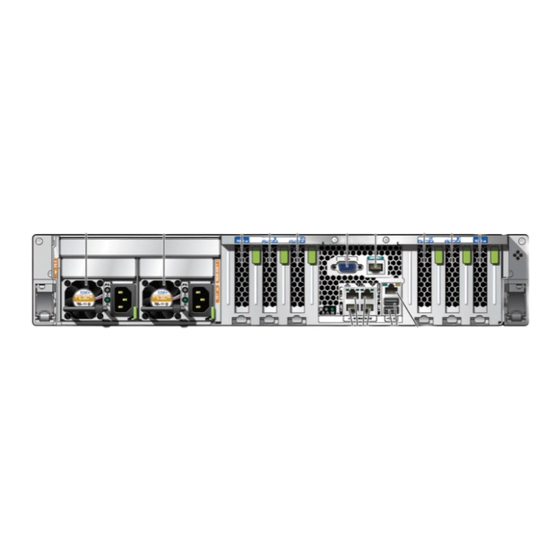
Page 13: Rear Panel Components
Rear Panel Components Description Drive 3 (or NVMe drive 1) Drive 2 (or NVMe drive 0) Drive 4 (or NVMe drive 2) Drive 5 (or NVMe drive 3) Drive 6 Drive 7 Related Information “Server Overview” on page 10 ■ “Rear Panel Components”... - Page 14 “Front Panel Components” on page 12 ■ “Connect Cables” on page 51 ■ “Attach the CMA to the Server” on page 41 ■ “Secure Cables to the CMA” on page 60 ■ SPARC T8-1 Server Installation Guide • June 2019...
-
Page 15: Preparing For Installation
Preparing for Installation These topics detail the precautions to follow and the tools to assemble prior to installing the server. Step Description Links Confirm that you received all the items you ordered. “Shipping Kit” on page 15 Review safety and ESD precautions “Handling Precautions”... - Page 16 PCIe cards were installed in the factory. Save these PCIe fillers and use them to cover PCIe slots when cards are removed from the server. Related Information “Server Overview” on page 10 ■ “Preparing for Installation” on page 15 ■ SPARC T8-1 Server Installation Guide • June 2019...
-
Page 17: Handling Precautions
“Physical Specifications” on page 19 ■ “Installing the Server” on page 25 ■ SPARC T8-1 Server Getting Started Guide ■ ESD Precautions Electronic equipment is susceptible to damage by static electricity. Use a grounded antistatic wrist strap, foot strap, or equivalent safety equipment to prevent electrostatic damage when you install or service the servers. -
Page 18: Tools Needed For Installation
■ Terminal server ■ Patch panel connected to a terminal server ■ Related Information “Handling Precautions” on page 17 ■ “ESD Precautions” on page 17 ■ SPARC T8-1 Server Service Manual ■ SPARC T8-1 Server Installation Guide • June 2019... -
Page 19: Specifications
Specifications These topics provide the technical information and airflow precautions you need to install the server. “Physical Specifications” on page 19 ■ “Electrical Specifications” on page 20 ■ “Environmental Specifications” on page 21 ■ “Airflow Precautions” on page 22 ■ Related Information “Server Overview”... -
Page 20: Electrical Specifications
620W / (120 * 0.90) = 6.89A You can use this equation to calculate your maximum operating current at your input voltage. For information on power specifications, use the power calculator at: http://www.oracle.com/us/products/servers-storage/sun-power-calculators Related Information “Powering On the Server for the First Time” on page 51 ■ SPARC T8-1 Server Installation Guide • June 2019... -
Page 21: Environmental Specifications
Environmental Specifications “Physical Specifications” on page 19 ■ “Environmental Specifications” on page 21 ■ “Airflow Precautions” on page 22 ■ Environmental Specifications This topic includes these specifications that apply to both server configurations: Temperature, humidity, and elevation ■ Shock and vibration ■... -
Page 22: Airflow Precautions
When servicing server internal components, ensure that air ducts, baffles, and filler panels ■ are properly installed. Route cables so they do not interfere with airflow. ■ Related Information “Rack Cautions” on page 27 ■ SPARC T8-1 Server Installation Guide • June 2019... - Page 23 Airflow Precautions “Physical Specifications” on page 19 ■ “Electrical Specifications” on page 20 ■ “Environmental Specifications” on page 21 ■ Specifications...
- Page 24 SPARC T8-1 Server Installation Guide • June 2019...
-
Page 25: Installing The Server
Installing the Server These topics describe how to install the server into a rack using the rail assembly in the rackmount kit. Perform these procedures if you purchased the rail assembly. Note - In this guide, the term rack means either an open rack or a closed cabinet. Step Description Links... -
Page 26: Rack Compatibility
Clearance width between front and rear Distance between structural supports and cable troughs is at least mounting planes 18 in. (456 mm). Server dimensions Depth: 29.0 in. (737 mm). Width: 17.5 in. (445 mm). SPARC T8-1 Server Installation Guide • June 2019... -
Page 27: Rack Cautions
Rack Cautions Item Requirement Height: 3.45 in. (87.6 mm). Related Information “Physical Specifications” on page 19 ■ “Handling Precautions” on page 17 ■ “Rack Cautions” on page 27 ■ Rack Cautions Equipment Loading. Always load equipment into a rack from the bottom up so that Caution - the rack does not become top-heavy and tip over. -
Page 28: Stabilize The Rack
If there are leveling feet beneath the rack to prevent it from rolling, extend these leveling feet fully downward to the floor. Install the rackmount hardware. “Install the Rackmount Hardware” on page SPARC T8-1 Server Installation Guide • June 2019... -
Page 29: Install The Rackmount Hardware
Install the Rackmount Hardware Related Information Rack documentation ■ SPARC T8-1 Server Safety and Compliance Guide ■ “Rack Compatibility” on page 26 ■ “Rack Cautions” on page 27 ■ Install the Rackmount Hardware Complete the following task to remove the mounting brackets from the slide rail assemblies before installation. - Page 30 Slide rail lock Mounting bracket Mounting bracket clip With the heads of the five chassis locating pins protruding through the five keyhole openings in the mounting bracket, pull the mounting bracket toward SPARC T8-1 Server Installation Guide • June 2019...
-
Page 31: Attach Slide Rail Assemblies To The Rack
Attach Slide Rail Assemblies to the Rack the front of the chassis until the mounting bracket clip locks into place with an audible click. Verify that the rear locating pin has engaged the mounting bracket clip. Repeat Step 2 through Step 4 to install the remaining mounting bracket on the other side of the server. - Page 32 The bottom edge of the card corresponds to the bottom edge of the server. Measure up from the bottom of the installation card. Mark the mounting holes for the front slide rails. Mark the mounting holes for the rear slide rails. SPARC T8-1 Server Installation Guide • June 2019...
- Page 33 Attach Slide Rail Assemblies to the Rack Orient the slide rail assembly so that the ball-bearing track is forward and locked in place. Description Slide rail Ball-bearing track Locking mechanism Installing the Server...
- Page 34 Repeat this procedure to attach the slide rail assembly to the other side of the rack. If available, extend the antitip legs or antitilt bar at the bottom of the rack. Refer to the documentation for the rack for instructions. SPARC T8-1 Server Installation Guide • June 2019...
-
Page 35: Install The Server Into The Slide Rail Assemblies
Install the Server Into the Slide Rail Assemblies Install the server into the slide rail assemblies. “Install the Server Into the Slide Rail Assemblies” on page Related Information “Rack Compatibility” on page 26 ■ “Install the Rackmount Hardware” on page 29 ■... - Page 36 Continue pushing the server into the rack until the slide rail locks (on the front of the mounting brackets) engage the slide rail assemblies. SPARC T8-1 Server Installation Guide • June 2019...
- Page 37 Install the Server Into the Slide Rail Assemblies You hear an audible click when the slide rail locks are engaged. Verify that the server is securely mounted in the rack and that the slide rail locks are Caution - engaged with the mounting brackets before you install the optional CMA. (Optional) If you chose to secure the slide rail assembly to the rack with screws, insert the M4 mounting screws that are provided with the rail kit, through the front left and right slide rail brackets and rack posts.
-
Page 38: Prepare The Cma For Installation
Install the server in the rack before attaching the CMA. “Install the Server Into the Slide Rail Assemblies” on page Unpack the CMA. The following figure shows the CMA components. Description Connector A Front slide bar SPARC T8-1 Server Installation Guide • June 2019... - Page 39 Connector D Slide rail latching bracket (used with connector D) Rear slide bar Flat cable covers (not used with SPARC T8-1) Round cable covers Ensure that the correct cable covers for your server are installed on the CMA. This server uses the round cable covers.
- Page 40 Swing the cable covers down and press down on the cable cover handle to lock them into the closed position. Ensure that the six Velcro straps are threaded into the CMA as shown in Step SPARC T8-1 Server Installation Guide • June 2019...
-
Page 41: Attach The Cma To The Server
Attach the CMA to the Server Ensure that the two Velcro straps located on the front slide bar are threaded through the Note - opening in the top of the slide bar as shown in Step 2. This prevents the Velcro straps from interfering with the expansion and contraction of the slide bar when the server is extended out of the rack and returned into the rack. - Page 42 Insert the CMA's connector B into the front slot on the right slide rail until it locks into place with an audible click (panels 1 and 2). The connector B tab goes into the slide rail's front slot (panel 1). SPARC T8-1 Server Installation Guide • June 2019...
- Page 43 Attach the CMA to the Server Gently tug on the right side of the front slide bar to verify that connector B is properly seated. Description Connector B tab Right slide rail front slot Install the CMA's connector C into the right slide rail. Installing the Server...
- Page 44 (panels 2 and 3). Gently tug on the right side of the CMA's rear slide bar to verify that connector C is properly seated. Prepare the CMA's connector D for installation. SPARC T8-1 Server Installation Guide • June 2019...
- Page 45 Attach the CMA to the Server Remove the tape that secures the slide rail latching bracket to connector D and ensure that the latching bracket is properly aligned with connector D (panels 1 and 2). Note - The CMA is shipped with the slide rail latching bracket taped to connector D. You must remove the tape before you install this connector.
- Page 46 Verify that the slide rails and CMA operate properly. “Verify Operation of Slide Rails and CMA” on page Related Information “Prepare the CMA for Installation” on page 38 ■ “Secure Cables to the CMA” on page 60 ■ SPARC T8-1 Server Installation Guide • June 2019...
-
Page 47: Verify Operation Of Slide Rails And Cma
Verify Operation of Slide Rails and CMA Verify Operation of Slide Rails and CMA Two people are recommended for this procedure, one to move the server in and out of Note - the rack, and one to observe the cables and CMA. Slowly pull the server out of the rack until the slide rails reach their stops. - Page 48 Adjust the cable straps and CMA, as required. Related Information “Attach the CMA to the Server” on page 41 ■ SPARC T8-1 Server Installation Guide • June 2019...
- Page 49 Verify Operation of Slide Rails and CMA “Secure Cables to the CMA” on page 60 ■ Installing the Server...
- Page 50 SPARC T8-1 Server Installation Guide • June 2019...
-
Page 51: Powering On The Server For The First Time
If using a CMA, connect cables to it now. “Secure Cables to the CMA” on page 60 Power on the server and start the Oracle ILOM “Power on the System for the First Time” on page 61 system console. - Page 52 A null modem configuration is needed, meaning the transmit and receive signals are reversed (crossed over) for DTE to DTE communications. You can use the supplied RJ-45 crossover adapters with a standard RJ-45 cable to achieve the null modem configuration. SPARC T8-1 Server Installation Guide • June 2019...
- Page 53 Connect Cables If you power on the server for the first time and do not have a terminal or terminal Note - emulator (PC or workstation) connected to the SP SER MGT port, you will not see system messages. Connect a Category 5 (or better) RJ-45 cable from the NET MGT port to your network switch or hub.
- Page 54 60 seconds if a terminal or terminal emulator is not connected to the SER MGT port before power is applied. Oracle ILOM signals a fault if both power supplies are not cabled at the same time, since Note - it will be a nonredundant condition.
-
Page 55: Identifying Ports
Identifying Ports “Identifying Ports” on page 55 ■ Identifying Ports This topic provide the pin descriptions of the ports. USB Ports Two USB 3.0 ports can be accessed from the rear of the server and two USB 2.0 ports from the front. -
Page 56: Ser Mgt Port
The NET MGT RJ-45 port, located on the rear panel, provides an optional Ethernet connection to the SP. The NET MGT port is an optional connection to Oracle ILOM on the SP. The SP NET MGT port uses an RJ-45 cable for a 1000BASE-T connection (auto-negotiates to 10 Mb/ sec, 100 Mb /sec, and 1 Gb/sec, full-duplex only). -
Page 57: Gigabit Ethernet Ports
Identifying Ports Signal Description Signal Description Transmit Data + No Connect Transmit Data – Receive Data – Receive Data + No Connect No Connect No Connect Gigabit Ethernet Ports Four RJ-45 Ethernet ports (NET 0, NET 1, NET 2, NET 3) can be accessed from the rear panel. “Rear Panel Components”... -
Page 58: Vga Port
VGA 12C Serial Clock Blue Ground SAS Ports The eight SAS connectors are located on the drive backplane inside the server. Four of the connectors also can be used by NVMe drives. SPARC T8-1 Server Installation Guide • June 2019... - Page 59 Identifying Ports The following table lists the pinouts for the SAS connector. Segment Signal Note Signal segment Second mate Transmit from PHY to hard drive (S1 to S7) Second mate Receive from hard drive to PHY Second mate Back-side signal Second mate (S8 to S14) Second mate...
-
Page 60: Secure Cables To The Cma
“Prepare the CMA for Installation” on page 38 “Attach the CMA to the Server” on page Open the cable covers and straps on the CMA. Route the server cables through the CMA cable covers and straps. SPARC T8-1 Server Installation Guide • June 2019... -
Page 61: Power On The System For The First Time
Administrator account as soon as possible after your initial login to Oracle ILOM. If you find this default Administrator account has already been changed, contact your system administrator to obtain an Oracle ILOM user account with Administrator privileges. -
Page 62: Installing The Os
■ “Reach a State to Install a Fresh OS (Oracle ILOM CLI)” on page 63 ■ “Reach a State to Install a Fresh OS (Oracle ILOM Web Interface)” on page 65 ■ Installing the OS Use these topics to either configure the preinstalled OS or use an alternative OS. -
Page 63: Configure The Preinstalled Os
Oracle Solaris OS parameters you must provide during initial configuration. Log in to the server. You can now enter Oracle Solaris OS commands at the prompt. For more details, refer to the Oracle Solaris 11 OS man pages and documentation at: http://www.oracle.com/goto/solaris11/docs Related Information “Power on the System for the First Time”... - Page 64 There are many methods by which you can install the OS. For example, you can boot and install the OS from external media or from another server on the network. For more information about the methods, refer to Installing Oracle Solaris 11 Systems, comparing installation options at: http://www.oracle.com/goto/solaris11/docs...
-
Page 65: Reach A State To Install A Fresh Os (Oracle Ilom Web Interface)
“Reach a State to Install a Fresh OS (Oracle ILOM CLI)” on page 63 ■ “Reach a State to Install a Fresh OS (Oracle ILOM Web Interface)” on page 65 ■ “Assign a Static IP Address to the NET MGT Port” on page 68 ■... - Page 66 Reach a State to Install a Fresh OS (Oracle ILOM Web Interface) In the Oracle ILOM web interface, in the left navigation pane, choose Host Management → Host Boot Mode. The Host Boot Mode page is displayed. Apply these changes to the Host Boot Mode Settings.
-
Page 67: Oracle Solaris Os Configuration Parameters
“Reach a State to Install a Fresh OS (Oracle ILOM CLI)” on page 63 ■ “Reach a State to Install a Fresh OS (Oracle ILOM Web Interface)” on page 65 ■ “Assign a Static IP Address to the NET MGT Port” on page 68 ■... -
Page 68: Assign A Static Ip Address To The Net Mgt Port
Accept the default date and time, or change the values. root Password Type the root password twice. This password is for the superuser account for the Oracle Solaris OS on this server. This password is not the SP password. Related Information Oracle Solaris OS documentation ■... - Page 69 To change the default IPv6 DHCP property and set property values for a static IPv6 address, refer to the section Modifying Default Connectivity Configuration Properties in the Oracle ILOM Administrator's Guide for Configuration and Maintenance. Set the IP address for the SP gateway.
-
Page 70: Oracle Auto Service Request Software Activation
Oracle's qualified server, storage, and Engineered System products when specific faults occur. Parts are dispatched upon receipt of a service request sent by Oracle ASR. In many cases, Oracle engineers are already working to resolve an issue before you're even aware that a problem exists. - Page 71 Oracle Auto Service Request Software Activation Oracle ASR is a feature of the Oracle hardware warranty, Oracle Premium Support for Systems, and Oracle Platinum Services. ■ https://www.oracle.com/support/premier/index.html ■ https://www.oracle.com/support/premier/engineered-systems/platinum-services. html Oracle ASR is integrated with My Oracle Support (https://support.oracle.com). You must use My Oracle Support to activate your ASR assets, such as a new server.
- Page 72 SPARC T8-1 Server Installation Guide • June 2019...
-
Page 73: Index
38 handling precautions, 17 mounting bracket, 41 heat dissipation specification, 20 securing cables, 60 height specification, 19 slide rail connector, 41 humidity specification, 21 configuring Oracle Solaris, 67 cooling fans, 10 CPU description, 10 current specifications, 20 I/O expansion, 10... - Page 74 25 rackmount Oracle Auto Service Request, 70 antitilt legs or bar, extending, 28 Oracle Solaris configuration parameters, 67 installing, 41 configuring the preinstalled OS, 63 slide rail connector, 41 SPARC T8-1 Server Installation Guide • June 2019...
- Page 75 Index installing cables, 41 frequency, 20 kit, 25 heat dissipation, 20 racks, supported, 26 humidity, 21 safety warnings, 27 physical, 19 slide rail assemblies, stops, releasing, verify power, 20 operation, 47 temperature, 21 stabilizing the rack, 28 vibration, 21 rear panel components, 13 voltage, 20 standby mode, 51...
- Page 76 SPARC T8-1 Server Installation Guide • June 2019...
Need help?
Do you have a question about the SPARC T8-1 and is the answer not in the manual?
Questions and answers