Table of Contents
Advertisement
Quick Links
Advertisement
Table of Contents

Related Manuals for Oracle SPARC T8-4


Summary of Contents for Oracle SPARC T8-4
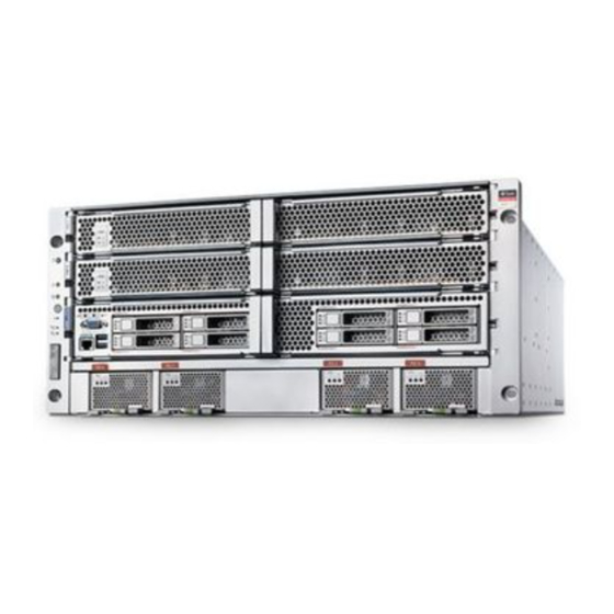
- Page 1 SPARC T8-4 Server Installation Guide Part No: E80509-01 September 2017...
- Page 3 Oracle. Oracle Corporation and its affiliates will not be responsible for any loss, costs, or damages incurred due to your access to or use of third-party content, products, or services, except as set forth in an applicable agreement between you and Oracle.
- Page 4 Oracle Corporation et ses affiliés déclinent toute responsabilité ou garantie expresse quant aux contenus, produits ou services émanant de tiers, sauf mention contraire stipulée dans un contrat entre vous et Oracle. En aucun cas, Oracle Corporation et ses affiliés ne sauraient être tenus pour responsables des pertes subies, des coûts occasionnés ou des dommages causés par l'accès à...
-
Page 5: Table Of Contents
Contents Using This Documentation ................. 9 Product Documentation Library ................. 9 Feedback ....................... 9 Understanding the Server ................. 11 Installation Task Overview ................ 11 Server Overview ................... 12 Front Panel Components ................. 14 Rear Panel Components .................. 15 Confirming Specifications ................. 17 Physical Specifications ................... 17 Electrical Specifications .................. 18 Environmental Requirements ................ 19 Airflow Precautions .................. 20 Preparing for Installation .................. - Page 6 ▼ Connect the Chassis Ground Wire ............... 66 ▼ Connect a Terminal or Emulator to the SER MGT Port ........ 67 ▼ Power on the Server for the First Time ............ 69 Oracle ILOM System Console ................. 70 Installing the OS ................... 71 SPARC T8-4 Server Installation Guide • September 2017...
- Page 7 ▼ Configure the Preinstalled OS ............ 71 ▼ Reach a State to Install a Fresh OS (Oracle ILOM CLI) ...... 72 ▼ Reach a State to Install a Fresh OS (Oracle ILOM Web Interface) .... 74 Oracle Solaris OS Configuration Parameters ............ 76 Assigning a Static IP Address to the SP ............ 77 ▼...
- Page 8 SPARC T8-4 Server Installation Guide • September 2017...
-
Page 9: Using This Documentation
Using This Documentation Overview – Provides specifications and describes how to install and power on Oracle's ■ SPARC T8-4 server for the first time Audience – Technicians, system administrators, and authorized service providers ■ Required knowledge – Advanced experience installing and configuring data center ■... - Page 10 SPARC T8-4 Server Installation Guide • September 2017...
-
Page 11: Understanding The Server
Understanding the Server These topics list the installation tasks, provide an overview of the SPARC T8-4 server, and highlight the key components. “Installation Task Overview” on page 11 ■ “Server Overview” on page 12 ■ “Front Panel Components” on page 14 ■... -
Page 12: Server Overview
Attach data and management cables to the server. “Connecting Cables” on page 51 Connect the power cords to the server, configure the Oracle “Powering On the Server for the First Time” on page 65 ILOM SP, power on the server for the first time, and set up the operating system. - Page 13 Server Overview Component Description Chassis Rack-mountable server with a 6RU form-factor 4x SPARC M8, 32-core chip multiprocessor (CMP) Memory 64 DDR4 DIMM slots. A server fully populated with 64-GB DIMMs supports a maximum of 4 TB of system memory. I/O expansion Sixteen PCIe Gen3 card slots: ■...
-
Page 14: Front Panel Components
SPARC T8-4 Server Service Manual ■ Oracle ILOM documentation ■ Front Panel Components Description Power button VGA port SER MGT port USB 3.0 ports Related Information “Cabling Requirements” on page 51 ■ SPARC T8-4 Server Installation Guide • September 2017... -
Page 15: Rear Panel Components
Rear Panel Components “Server Overview” on page 12 ■ “Rear Panel Components” on page 15 ■ Rear Panel Components You must follow the proper sequence when connecting cables to the server. Do not Note - connect the power cords until all data cables have been connected. Description Links Power supply unit AC inputs (4) - Page 16 Related Information “Front Panel Components” on page 14 ■ “Cabling Requirements” on page 51 ■ “Installing the CMA (Optional)” on page 41 ■ “Secure Cables Using the CMA” on page 61 ■ SPARC T8-4 Server Installation Guide • September 2017...
-
Page 17: Confirming Specifications
Confirming Specifications These topics provide the technical information and airflow precautions you need to install the server. “Physical Specifications” on page 17 ■ “Electrical Specifications” on page 18 ■ “Environmental Requirements” on page 19 ■ “Airflow Precautions” on page 20 ■... -
Page 18: Electrical Specifications
■ “Airflow Precautions” on page 20 ■ Electrical Specifications Use these specifications only as a general planning guide. To determine power values based on expected workloads, use the SPARC T8-4 power calculator at: http://www.oracle.com/goto/powercalculators/ Description Value Operating input range 200 to 240 VAC, 50/60 Hz †... -
Page 19: Environmental Requirements
Environmental Requirements Related Information “Powering On the Server for the First Time” on page 65 ■ “Physical Specifications” on page 17 ■ “Environmental Requirements” on page 19 ■ “Airflow Precautions” on page 20 ■ Environmental Requirements This topic includes these specifications: Temperature, humidity, and elevation ■... -
Page 20: Airflow Precautions
Install the server so the front faces the cool aisle and the rear faces the warm aisle. ■ Do not direct warm air into the server. ■ Prevent recirculation of air within a rack or cabinet. ■ SPARC T8-4 Server Installation Guide • September 2017... - Page 21 Airflow Precautions When servicing server internal components, ensure that air ducts and baffles are properly ■ installed. Route cables so they do not interfere with airflow. ■ Related Information “Rack Cautions” on page 30 ■ “Physical Specifications” on page 17 ■...
- Page 22 SPARC T8-4 Server Installation Guide • September 2017...
-
Page 23: Preparing For Installation
Preparing for Installation These topics detail the precautions to follow, the tools to assemble, and the tasks to perform prior to installing the server. Step Description Links Confirm that you have received all the items you ordered “Shipping Kit” on page 23 for the type of rackmount kit you will be using in your installation. - Page 24 Shipping Kit Description Server Rack Buddy template AC power cords (4) RJ-45 to DB-9 crossover adapter RJ-45 to DB-25 crossover adapter Print document kit Antistatic wrist strap Ethernet cables (2) Rackmounting kit Fasteners SPARC T8-4 Server Installation Guide • September 2017...
-
Page 25: Handling Precautions
“ESD Precautions” on page 25 ■ “Installing the Server” on page 29 ■ SPARC T8-4 Server Getting Started Guide ■ ESD Precautions Electronic equipment is susceptible to damage by static electricity. Use a grounded antistatic wriststrap, footstrap, or equivalent safety equipment to prevent electrostatic damage when you install or service the server. -
Page 26: Tools Needed For Installation
Terminal server (optional to capture initial boot output) ■ Patch panel connected to a terminal server ■ Related Information “Handling Precautions” on page 25 ■ “ESD Precautions” on page 25 ■ SPARC T8-4 Server Service Manual ■ SPARC T8-4 Server Installation Guide • September 2017... -
Page 27: Prepare The Server
Remove all of the processor modules, the main module, the power supplies, and the fan modules from the server. Refer to the SPARC T8-4 Server Service Manual for detailed instructions. Determine your next step: For a one-person installation, place the server on a mechanical lift. - Page 28 SPARC T8-4 Server Installation Guide • September 2017...
-
Page 29: Installing The Server
Review cabling requirements and port “Connecting Cables” on page 51 information. Attach data and management cables to the server. Configure the Oracle ILOM SP and power on “Powering On the Server for the First the server for the first time. Time” on page 65 Related Information “Understanding the Server”... -
Page 30: Rack Compatibility
CMA installed. If you are installing the server in a non-Oracle rack, ensure that the non-Oracle rack meets the server installation requirements, which include (but are not limited to) the following: The server must be placed on a rack shelf in the non-Oracle rack. - Page 31 Rack Cautions Elevated Operating Ambient Temperature: If the server is installed in a closed or Caution - multi-unit rack assembly, the operating ambient temperature of the rack environment might be greater than room ambient temperature. Therefore, install the equipment only in an environment compatible with the maximum ambient temperature (Tma) specified for the server.
-
Page 32: Stabilize The Rack
If there are leveling feet beneath the rack to prevent it from rolling, extend these leveling feet fully downward to the floor. Install the rackmount kit. “Installing the Rackmount Kit” on page Related Information “Installing the Rackmount Kit” on page 33 ■ SPARC T8-4 Server Installation Guide • September 2017... -
Page 33: Installing The Rackmount Kit
Installing the Rackmount Kit Rack documentation ■ SPARC T8-4 Server Safety and Compliance Guide ■ “Rack Compatibility” on page 30 ■ “Rack Cautions” on page 30 ■ Installing the Rackmount Kit These topics describe how to install the rackmount hardware. - Page 34 M6 x 12-mm screws (16) M4 x 10mm flathead screws (4) 10-32 shoulder screws (12) Some of the fastener bags that are included in the kit are not required to install this Note - server. SPARC T8-4 Server Installation Guide • September 2017...
-
Page 35: Determine Correct Rackmount Hardware
Determine Correct Rackmount Hardware Determine Correct Rackmount Hardware Ensure that the rack is stabilized. “Stabilize the Rack” on page Determine the hardware needed for your rack installation. Rack Type Fastener Bags Required Square hole SCREW, SEMS, M6 X 16 CAGE NUTS, M6 Round hole (10-32) with corner bezel SCREW, SEMS, 10-32 X 10 SCREW, FLAT HEAD, M4 X 10... -
Page 36: Mark The Rackmounting Location
The bottom edge of the template corresponds to the bottom edge of the server. Measure up from the bottom of the template. Mark the mounting holes for the front shelf rails. Mark the mounting holes for the rear shelf rails. Related Information “Rack Compatibility” on page 30 ■ SPARC T8-4 Server Installation Guide • September 2017... -
Page 37: Install The Shelf Rails
Install the Shelf Rails “Installing the Rackmount Kit” on page 33 ■ “Determine Correct Rackmount Hardware” on page 35 ■ “Install the Shelf Rails” on page 37 ■ Install the Shelf Rails Place the left shelf rail in the marked location. The shelf rails are marked FRONT LEFT and FRONT RIGHT (as viewed from the front Note - of the server). - Page 38 If you are installing the server into an equipment rack that will be ■ shipped to another location, see “Installing the Shipping Brace Assembly (Optional)” on page If you are installing the server, see “Installing the Server” on page ■ SPARC T8-4 Server Installation Guide • September 2017...
-
Page 39: Install The Server
■ All five fan modules ■ Refer to the SPARC T8-4 Server Service Manual for removal instructions. If you are using a mechanical lift, ensure that the lift is level and stable. Lift the server up to the correct height. - Page 40 Secure the server to the front panel using four No. 2 Phillips screws. Replace all of the components that you removed. Both processor modules ■ The main module ■ All four power supplies ■ All five fan modules ■ SPARC T8-4 Server Installation Guide • September 2017...
-
Page 41: Installing The Cma (Optional)
Installing the CMA (Optional) Refer to the SPARC T8-4 Server Service Manual for installation instructions. Related Information “Rack Compatibility” on page 30 ■ “Rack Cautions” on page 30 ■ “Stabilize the Rack” on page 32 ■ “Installing the Rackmount Kit” on page 33 ■... -
Page 42: Cma Kit Overview
CMA comb M6 16-mm screws (4) Hook and loop straps (14) M6 cage nuts (4) M6 6-mm screws (6) Bracket adapters (2) Related Information “Determine Correct Rackmount Hardware” on page 35 ■ SPARC T8-4 Server Installation Guide • September 2017... -
Page 43: Install The Cma
Install the CMA “Install the CMA” on page 43 ■ “Secure Cables Using the CMA” on page 61 ■ Install the CMA Attach the CMA to the rear posts of the rack. The CMA installation might block some of the power outlets in the rack, making them Note - unavailable. - Page 44 Push the server forward 3 in. (76 mm). Attach the CMA to the rack posts, using two M6 screws for each side. Consider your next steps: If the server is already installed, do the following: ■ SPARC T8-4 Server Installation Guide • September 2017...
-
Page 45: Installing The Shipping Brace Assembly (Optional)
Installing the Shipping Brace Assembly (Optional) At the front of the server, push the server back until it touches the rails. Reinstall the four faceplate screws, two for each side. If the server is not already installed, install the server. ■... -
Page 46: Shipping Brace Overview
The shipping braces and necessary fasteners are included with the rackmount kit. Description Top rear shipping brace (2) Guide pins (2) Cage nuts (4) Bottom rear shipping brace Screws (8) SPARC T8-4 Server Installation Guide • September 2017... -
Page 47: Determine Correct Shipping Brace Fasteners
Determine Correct Shipping Brace Fasteners Related Information “Tools Needed for Installation” on page 26 ■ “Rack Compatibility” on page 30 ■ “Determine Correct Rackmount Hardware” on page 35 ■ “Mark the Rackmounting Location” on page 36 ■ Determine Correct Shipping Brace Fasteners Determine the correct fasteners for your shipping brace installation. - Page 48 Step 1 through Step 4 for the top right shipping brace. Related Information “Determine Correct Shipping Brace Fasteners” on page 47 ■ “Install the Bottom Rear Shipping Brace” on page 49 ■ SPARC T8-4 Server Installation Guide • September 2017...
-
Page 49: Install The Bottom Rear Shipping Brace
Install the Bottom Rear Shipping Brace Install the Bottom Rear Shipping Brace Position the shipping brace at the bottom rear of the system. Secure each side of the bottom rear shipping brace with two M6 x 12-mm screws. Related Information “Determine Correct Shipping Brace Fasteners”... -
Page 50: Remove The Bottom Rear Shipping Brace
Slide the shipping brace out from the rear of the rack. Related Information “Determine Correct Shipping Brace Fasteners” on page 47 ■ “Install the Top Rear Shipping Braces” on page 47 ■ “Install the Bottom Rear Shipping Brace” on page 49 ■ SPARC T8-4 Server Installation Guide • September 2017... -
Page 51: Connecting Cables
Serial management port (SER MGT port): SP local connection with Oracle ILOM boot ■ messages Power cables for the server power supplies ■ SP management ports: There are two SP management ports for use with the Oracle ILOM ■ Connecting Cables... - Page 52 The SER MGT port uses an RJ-45 cable and is always available. This port is the default ■ connection to the ILOM SP. The NET MGT port is the optional connection to the Oracle ILOM SP. The NET MGT ■ port is configured to use DHCP by default. To set a static IP address, see “Assigning a...
-
Page 53: Identifying Ports
Identifying Ports Identifying Ports “USB Ports” on page 53 ■ “SER MGT Ports” on page 54 ■ “NET MGT Port” on page 55 ■ “Ethernet Ports” on page 56 ■ “VGA Port” on page 57 ■ Related Information “Server Overview” on page 12 ■... -
Page 54: Ser Mgt Ports
The SER MGT RJ-45 port, located on the rear panel, provides an TIA/EIA-232 serial Oracle/ Cisco standard connection to the SP. This port is the default connection to the Oracle ILOM SP. For DTE to DTE communications, you can use the supplied RJ-45 to DB-9 crossover adapter with a standard RJ-45 cable to achieve the required null modem configuration. -
Page 55: Net Mgt Port
The NET MGT RJ-45 port, located on the rear panel, provides an optional Ethernet connection to the SP. The NET MGT port is an optional connection to the Oracle ILOM SP. The SP NET MGT port uses an RJ-45 cable for a 10GBASE-T connection. If your network does not use a DHCP server, this port will not be available until you configure network settings through the SER MGT port. -
Page 56: Ethernet Ports
NET 3) are located on the system rear panel. See “Rear Panel Components” on page 15. The Ethernet interfaces operate at 100 Mbps, 1 Gbps, 10 Gbps. Signal Description Signal Description Transmit/Receive Data 0 + Transmit/Receive Data 2 – SPARC T8-4 Server Installation Guide • September 2017... -
Page 57: Vga Port
Only one of the two ports can be used at a time. The rear VGA port is disabled by Note - default. To enable the rear port and disable the front port, you must enable the Oracle ILOM VGA_REAR_PORT policy. Type: ->... -
Page 58: Connecting Data And Management Cables
“Connect Other Data Cables” on page 61 ■ Related Information “Server Overview” on page 12 ■ “Front Panel Components” on page 14 ■ “Rear Panel Components” on page 15 ■ “Cabling Requirements” on page 51 ■ SPARC T8-4 Server Installation Guide • September 2017... -
Page 59: Connect The Ser Mgt Cable
Connect the SER MGT Cable “Identifying Ports” on page 53 ■ Connect the SER MGT Cable The SER MGT port on the SP is marked SER MGT. The SP SER MGT port is only used for server management. It is the default connection between the SP and a terminal or a computer. “Front Panel Components”... -
Page 60: Connect The Ethernet Network Cables
1000 Mbps, and 10000 Mbps. See “Rear Panel Components” on page 15 for port locations. The Oracle ILOM sideband management feature enables you to access the SP using one Note - of these Ethernet ports. Refer to the administration guide for your server for instructions. -
Page 61: Connect Other Data Cables
■ “Cabling Requirements” on page 51 ■ PCIe card documentation ■ SPARC T8-4 Server Service Manual ■ Secure Cables Using the CMA Use the CMA to secure cables and ensure proper cable routing. Nest and bundle the cables as appropriate. - Page 62 Secure Cables Using the CMA Use the supplied hook and loop fasteners to secure the cables in the CMA. If necessary, tilt the CMA up or down to direct the cables as appropriate. SPARC T8-4 Server Installation Guide • September 2017...
- Page 63 Secure Cables Using the CMA Pull the release tabs out to unlock the CMA comb. Rotate the CMA comb up or down as needed, and push the release tabs in to lock the CMA comb in the desired position. Related Information “Installing the CMA (Optional)”...
- Page 64 SPARC T8-4 Server Installation Guide • September 2017...
-
Page 65: Powering On The Server For The First Time
Configure the preinstalled OS, or install a fresh OS. “Configure the Preinstalled OS” on page 71 “Reach a State to Install a Fresh OS (Oracle ILOM CLI)” on page 72 Set the configuration parameters for the Oracle Solaris “Oracle Solaris OS Configuration Parameters” on page 76 (Optional.) Configure the NET MGT port to use a static... -
Page 66: Connect The Chassis Ground Wire
(PC or workstation). The server goes into Standby mode and the Oracle ILOM SP initializes as soon as a power cable connects a power supply to an external power source. System messages might be lost after 60 seconds if a terminal or terminal emulator is not connected to the SER MGT port before power is applied. -
Page 67: Connect A Terminal Or Emulator To The Ser Mgt Port
Connect a Terminal or Emulator to the SER MGT Port Go to the rear of the server and locate the two grounding holes beneath fan module 4 (FM4). Position and align the grounding lug on the two grounding holes at the rear of the chassis. - Page 68 After a few minutes, the SP login prompt is displayed on the terminal device. At this time, the host is not initialized or powered on. Continue with the installation by powering on the server for the first time. “Power on the Server for the First Time” on page SPARC T8-4 Server Installation Guide • September 2017...
-
Page 69: Power On The Server For The First Time
■ “Reach a State to Install a Fresh OS (Oracle ILOM CLI)” on page 72 ■ “Reach a State to Install a Fresh OS (Oracle ILOM Web Interface)” on page 74 ■ Power on the Server for the First Time At the terminal device, log in to the SP as root with a password of changeme. -
Page 70: Oracle Ilom System Console
■ “Reach a State to Install a Fresh OS (Oracle ILOM CLI)” on page 72 ■ “Reach a State to Install a Fresh OS (Oracle ILOM Web Interface)” on page 74 ■ Oracle ILOM System Console When power is first applied to the system, the boot process begins under the control of the Oracle ILOM system console. -
Page 71: Installing The Os
“Reach a State to Install a Fresh OS (Oracle ILOM CLI)” on page 72 ■ “Reach a State to Install a Fresh OS (Oracle ILOM Web Interface)” on page 74 ■ “Assign a Static IP Address to the NET MGT Port” on page 79 ■... -
Page 72: Reach A State To Install A Fresh Os (Oracle Ilom Cli)
Oracle Solaris OS parameters you must provide during initial configuration. Log in to the server. You can now enter Oracle Solaris OS commands at the prompt. For more details, refer to the Oracle Solaris OS man pages and documentation at: http://www.oracle.com/goto/solaris11/docs Related Information “Prepare the Power Cords”... - Page 73 The server might take several minutes to complete POST. Then the OpenBoot prompt (ok) is displayed. Boot from the appropriate boot media for your installation method. For more information, refer to Installing Oracle Solaris 11 Systems, comparing installation options at. http://www.oracle.com/goto/solaris11/docs...
-
Page 74: Reach A State To Install A Fresh Os (Oracle Ilom Web Interface)
“Reach a State to Install a Fresh OS (Oracle ILOM CLI)” on page 72 ■ “Reach a State to Install a Fresh OS (Oracle ILOM Web Interface)” on page 74 ■ “Assign a Static IP Address to the NET MGT Port” on page 79 ■... - Page 75 Reach a State to Install a Fresh OS (Oracle ILOM Web Interface) For Script, type: ■ setenv auto-boot? false This setting configures the host to stop at the ok prompt instead of automatically booting the preinstalled OS. Click Save. You have 10 minutes to perform the next step. After 10 minutes, the state is Note - automatically returned to normal.
-
Page 76: Oracle Solaris Os Configuration Parameters
“Reach a State to Install a Fresh OS (Oracle ILOM CLI)” on page 72 ■ “Reach a State to Install a Fresh OS (Oracle ILOM Web Interface)” on page 74 ■ “Assign a Static IP Address to the NET MGT Port” on page 79 ■... -
Page 77: Assigning A Static Ip Address To The Sp
Accept the default date and time or change the values. root Password Type the root password twice. This password is for the superuser account for the Oracle Solaris OS on this server. This password is not the SP password. Related Information Oracle Solaris OS documentation ■... - Page 78 Log In to the SP (SER MGT Port) configuration provides an Oracle ILOM CLI root user account. The default root password is . Change the password using the Oracle ILOM CLI set /HOST/users/root password changeme command. If this is the first time the server has been powered on, change the root password.
-
Page 79: Assign A Static Ip Address To The Net Mgt Port
If the network your server is connected to does not support DHCP for IP addressing, perform this procedure. To configure the server to support DHCP, refer to the Oracle ILOM documentation. Note - Set the SPM to accept a static IP address. -
Page 80: Auto Service Request Software
■ “Reach a State to Install a Fresh OS (Oracle ILOM CLI)” on page 72 ■ “Reach a State to Install a Fresh OS (Oracle ILOM Web Interface)” on page 74 ■ “Oracle Solaris OS Configuration Parameters” on page 76 ■... -
Page 81: Related Information
For more information on setting up and installing support automation on the server, please refer Oracle Auto Service Request Quick Installation Guide. Or log in to your My Oracle Support account to access the "Oracle Auto Service Request (Doc ID 1185493.1)" knowledge article located at: http://support.oracle.com/epmos/faces/DocumentDisplay?id=1185493.1. - Page 82 SPARC T8-4 Server Installation Guide • September 2017...
-
Page 83: Glossary
Auto Service Request. Automatic system recovery. American wire gauge. Baseboard management controller. Memory buffer on board. chassis Server enclosure. Cable management arm (SPARC T8-1 and SPARC T8-2). Cable management assembly (SPARC T8-4). Chip multiprocessor. Customer-replaceable unit. DHCP Dynamic Host Configuration Protocol. Glossary... - Page 84 Host bus adapter. host The part of the server or server module with the CPU and other hardware that runs the Oracle Solaris OS and other applications. The term host is used to distinguish the primary computer from the SP. See SP.
- Page 85 Keyboard, video, and mouse. Refers to using a switch to enable sharing of one keyboard, one display, and one mouse with more than one computer. LDom Logical domain managed by Oracle VM Server for SPARC. See Oracle VM Server for SPARC.
- Page 86 OpenBoot PROM. Sometimes OBP is used in file names and messages to indicate a relationship to OpenBoot. Oracle ILOM Oracle Integrated Lights Out Manager. Oracle ILOM firmware is preinstalled on a variety of Oracle systems. Oracle ILOM enables you to remotely manage your Oracle servers regardless of the state of the host system.
- Page 87 Service processor. In the server, the SP is a card with its own OS that is operating and accessible whenever the server power cords are connected and energized, regardless of host power state. The SP processes Oracle ILOM commands providing lights out management control of the host. See host.
- Page 88 SPARC T8-4 Server Installation Guide • September 2017...
-
Page 89: Index
Index hardware required, 41 installing, 41, 43 acoustic specifications, 20 kit, 41 adapters for serial cables, 59 securing cables, 61 admin login, setting password for, 77 compatible racks, 30, 30 airflow components clearance, 20 rear, 15 guidelines, 20 airflow guidelines, 20 altitude specifications, 19 antitilt legs or bar, 32 ASR, 80... - Page 90 Oracle Solaris OS, configuring, 71 messages retention, limits of, 51 minimum cable connections, 51 modem not for use with the SER MGT port, 59 rack cautions, 30 NET MGT port compatibility, 30 SPARC T8-4 Server Installation Guide • September 2017...
- Page 91 Index mounting holes, supported, 30 shipping kit contents, 23 stabilizing, 32 site planning specifications, 17 rackmount slots, ports, and LEDs illustrated, 15 antitilt legs or bar, extending, 32 specifications hardware, 35 acoustic, 20 installing the hardware, 37 confirming, 17 preparing the server, 27 electrical, 18 safety warnings, 30 elevation, 19...
- Page 92 Index described, 12 front, 14 pinouts, 57 rear, 15 weight specifications, 17 width specifications, 17 SPARC T8-4 Server Installation Guide • September 2017...
Need help?
Do you have a question about the SPARC T8-4 and is the answer not in the manual?
Questions and answers