Oracle SPARC T7-2 Service Manual
Hide thumbs
Also See for SPARC T7-2:
- Installation manual (78 pages) ,
- Getting started manual (6 pages) ,
- Safety and compliance manual (100 pages)
Table of Contents
Advertisement
Quick Links
Advertisement
Table of Contents

Related Manuals for Oracle SPARC T7-2


Summary of Contents for Oracle SPARC T7-2
- Page 1 SPARC T7-2 Server Service Manual Part No: E54987-10 July 2019...
- Page 3 Oracle. Oracle Corporation and its affiliates will not be responsible for any loss, costs, or damages incurred due to your access to or use of third-party content, products, or services, except as set forth in an applicable agreement between you and Oracle.
- Page 4 Oracle Corporation et ses affiliés déclinent toute responsabilité ou garantie expresse quant aux contenus, produits ou services émanant de tiers, sauf mention contraire stipulée dans un contrat entre vous et Oracle. En aucun cas, Oracle Corporation et ses affiliés ne sauraient être tenus pour responsables des pertes subies, des coûts occasionnés ou des dommages causés par l'accès à...
-
Page 5: Table Of Contents
Server Block Diagram .................. 25 Detecting and Managing Faults ................ 29 Checking for Faults .................. 29 Related Information ................ 30 ▼ Log In to Oracle ILOM (Service) ............ 30 ▼ Identify Faulted Components .............. 31 ▼ Identify Disabled Components ............ 33 Component Names Displayed by Diagnostic Software ......... 34 Interpreting LEDs .................. 35 Front Panel Controls and LEDs ............... - Page 6 Attaching Devices During Service .............. 63 Servicing Drives .................... 65 Drive LEDs .................... 66 ▼ Determine Which Drive Is Faulty ............... 67 ▼ Remove a Drive .................. 67 ▼ Remove a Drive Filler ................ 71 ▼ Install a Drive .................. 72 SPARC T7-2 Server Service Manual • July 2019...
- Page 7 Memory Riser and DIMM FRU Names ............. 93 ▼ Add Memory to the Server ................ 95 Locating and Replacing a Faulty DIMM ............ 96 ▼ Locate a Faulty DIMM (Oracle ILOM) .......... 96 ▼ Locate a Faulty DIMM (LEDs) ............ 97 ▼ Replace a Faulty DIMM .............. 99 ▼...
- Page 8 Servicing the Motherboard ................ 147 ▼ Remove the Motherboard ................. 147 ▼ Install the Motherboard ................ 151 ▼ Reactivate RAID Volumes ............... 155 ▼ Verify the Motherboard ................ 158 Servicing the Drive Backplane ................ 159 ▼ Remove the Drive Backplane .............. 159 SPARC T7-2 Server Service Manual • July 2019...
- Page 9 ▼ Replace the Top Cover ................ 172 ▼ Return the Server to the Normal Operating Position ........ 173 ▼ Attach Power Cords ................ 174 ▼ Power On the Server (Oracle ILOM) ............ 174 ▼ Power On the Server (System Power Button) .......... 175 Glossary ...................... 177 Index ........................ 183...
- Page 10 SPARC T7-2 Server Service Manual • July 2019...
-
Page 11: Using This Documentation
Audience – Technicians, system administrators, and authorized service providers ■ Required knowledge – Advanced experience troubleshooting and replacing hardware ■ Product Documentation Library Documentation and resources for this product and related products are available at http://www. oracle.com/goto/t7-2/docs. Feedback Provide feedback about this documentation at http://www.oracle.com/goto/docfeedback. Using This Documentation... - Page 12 SPARC T7-2 Server Service Manual • July 2019...
-
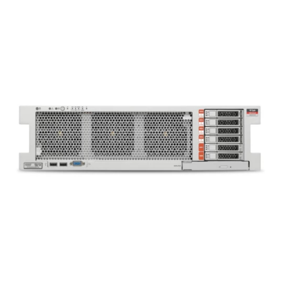
Page 13: Identifying Components
These topics identify key components of the server, including major boards and internal system cables, as well as front and rear panel features. For system overview information, see “Understanding the Server” in SPARC T7-2 Server Installation Guide. “Front Panel Components (Service)” on page 13 ■... - Page 14 Server Installation, USB port DB-15 video connector Server Installation, video port SATA DVD drive “Servicing the DVD Drive” on page 113 Drives 0 to 5 (numbered bottom to top) “Servicing Drives” on page 65 SPARC T7-2 Server Service Manual • July 2019...
-
Page 15: Rear Panel Components (Service)
Rear Panel Components (Service) Related Information “Rear Panel Components (Service)” on page 15 ■ “Rear Panel Components (Service)” on page 15 ■ “Motherboard Component Locations” on page 21 ■ “I/O Component Locations” on page 22 ■ “Power Distribution and Fan Module Component Locations” on page 24 ■... -
Page 16: Internal System Cables
SAS controller or to a PCI-E low-profile form factor HBA option. Related Information “Internal Component Locations” on page 17 ■ “Power Distribution and Fan Module Component Locations” on page 24 ■ SPARC T7-2 Server Service Manual • July 2019... -
Page 17: Server Top View
Server Top View Server Top View The following figure shows a top view of the server with the top cover removed. Related Information “Front Panel Components (Service)” on page 13 ■ “Rear Panel Components (Service)” on page 15 ■ “Internal System Cables” on page 16 ■... - Page 18 /SYS/MB/SPM PCIe card (in slot 1) “Servicing PCIe Cards” on page 125 /SYS/MB/PCIE1 /SYS/MB/PCIE2 /SYS/MB/PCIE3 /SYS/MB/PCIE4 /SYS/MB/PCIE5 /SYS/MB/PCIE6 /SYS/MB/PCIE7 /SYS/MB/PCIE8 Power supplies “Servicing Power /SYS/PS0 (outer) Supplies” on page 85 /SYS/PS1 (inner) SPARC T7-2 Server Service Manual • July 2019...
- Page 19 Internal Component Locations Component Oracle ILOM Target Links PS backplane and cover “Servicing the PS /SYS/PDB Backplane” on page 165 Drive backplane “Servicing the Drive /SYS/DBP Backplane” on page 159 Motherboard “Servicing the /SYS/MB Motherboard” on page 147 Battery “Servicing the Battery” on page 117...
- Page 20 “Motherboard Component Locations” on page 21 ■ “I/O Component Locations” on page 22 ■ “Power Distribution and Fan Module Component Locations” on page 24 ■ “Server Block Diagram” on page 25 ■ SPARC T7-2 Server Service Manual • July 2019...
-
Page 21: Motherboard Component Locations
Motherboard Component Locations Motherboard Component Locations Component Oracle ILOM Target LInks SP module “Servicing the SPM” on page 135 /SYS/MB/SPM Memory riser “Servicing Memory Risers and /SYS/MB/CMn/CMP/MRn DIMMs” on page 91 DIMMs “Servicing Memory Risers and /SYS/MB/CMn/CMP/MRn/BOBn/CHn/D0 DIMMs” on page 91 Motherboard “Servicing the... -
Page 22: I/O Component Locations
“Servicing the Motherboard” on page 147 ■ “Servicing the Battery” on page 117 ■ I/O Component Locations Component Oracle ILOM Target LInks Drives “Servicing /SYS/DBP/HDD0 (bottom) Drives” on page 65 /SYS/DBP/HDD1 /SYS/DBP/HDD2 SPARC T7-2 Server Service Manual • July 2019... - Page 23 I/O Component Locations Component Oracle ILOM Target LInks /SYS/DBP/HDD3 /SYS/DBP/HDD4 /SYS/DBP/HDD5 (top) Light pipe assembly “Servicing the Drive Backplane” on page 159 DVD drive “Servicing the DVD /SYS/DBP/DVD Drive” on page 113 Drive backplane “Servicing the Drive /SYS/DBP Backplane” on page 159 Related Information “Component Service Categories”...
-
Page 24: Power Distribution And Fan Module Component Locations
“Servicing the PS /SYS/PDB Backplane” on page 165 Power supplies “Servicing Power /SYS/PS0 (outer) Supplies” on page 85 /SYS/PS1 (inner) Fan modules “Servicing Fan /SYS/FANBD/F0 Modules” on page 77 /SYS/FANBD/F1 /SYS/FANBD/F2 /SYS/FANBD/F3 /SYS/FANBD/F4 SPARC T7-2 Server Service Manual • July 2019... -
Page 25: Server Block Diagram
Server Block Diagram Component Oracle ILOM Target Links /SYS/FANBD/F5 Fan board “Servicing the Fan /SYS/FANBD Board” on page 141 Related Information “Internal System Cables” on page 16 ■ “Component Service Categories” on page 50 ■ “Servicing Power Supplies” on page 85 ■... - Page 26 Server Block Diagram Related Information “Component Service Categories” on page 50 ■ “Internal Component Locations” on page 17 ■ “Motherboard Component Locations” on page 21 ■ SPARC T7-2 Server Service Manual • July 2019...
- Page 27 Server Block Diagram “I/O Component Locations” on page 22 ■ “Power Distribution and Fan Module Component Locations” on page 24 ■ Identifying Components...
- Page 28 SPARC T7-2 Server Service Manual • July 2019...
-
Page 29: Detecting And Managing Faults
Use these tools to identify components that require service. Step Description Links “Log In to Oracle ILOM (Service)” on page 30 Run the fmadm faulty command to display information about components “Identify Faulted Components” on page 31 that require service. -
Page 30: Related Information
At the terminal prompt, type: ssh root@SP-IP-address Password: password Oracle (R) Integrated Lights Out Manager Version 3.2.x Copyright (c) 2014, Oracle and/or its affiliates, Inc. All rights reserved. -> Related Information “Identify Faulted Components” on page 31 ■ “Identify Disabled Components” on page 33 ■... -
Page 31: Identify Faulted Components
From the Oracle ILOM prompt, start the fault management shell and type fmadm faulty. This example shows how to check for faults through the Oracle ILOM fault management shell. You can also check for faults by typing show faulty at the Oracle ILOM prompt. - Page 32 Obtain the message ID from console output (SPT-8000-PX in the example above). Go to https://support.oracle.com, and search on the message ID in the Knowledge tab, or type the URL from the Action field into a browser. Follow the suggested actions to repair the fault.
-
Page 33: Identify Disabled Components
Identify Disabled Components Identify Disabled Components You can run the show disabled command from the Oracle ILOM prompt to identify components that have been disabled either intentionally, by a user, or automatically, because of a fault. At the Oracle ILOM prompt, type: ->... -
Page 34: Component Names Displayed By Diagnostic Software
/SYS/FANBD/F0 (left front) /SYS/FANBD/F1 (center front) /SYS/FANBD/F2 (right front) /SYS/FANBD/F3 (left rear) /SYS/FANBD/F4 (center rear) /SYS/FANBD/F5 (right rear) Memory risers “Servicing Memory Risers and /SYS/MB/CM0/CMP/MR0 DIMMs” on page 91 /SYS/MB/CM0/CMP/MR1 /SYS/MB/CM0/CMP/MR2 /SYS/MB/CM0/CMP/MR3 /SYS/MB/CM1/CMP/MR0 SPARC T7-2 Server Service Manual • July 2019... -
Page 35: Interpreting Leds
“Servicing the PS /SYS/PDB Backplane” on page 165 “Servicing the SPM” on page 135 /SYS/MB/SPM Related Information “Log In to Oracle ILOM (Service)” on page 30 ■ “Identify Faulted Components” on page 31 ■ “Identify Disabled Components” on page 33 ■... -
Page 36: Front Panel Controls And Leds
You can turn on the Locator LED to identify a particular server. When lit, the LED blinks Locator LED and rapidly. Turn on the Locator LED by pressing the Locator button with a stylus, or see button (white) “Locate the Server” on page SPARC T7-2 Server Service Manual • July 2019... - Page 37 ■ Steady on, green – SPM is running in its normal operating state. No service actions are required. ■ Blink, green – SPM is initializing the Oracle ILOM firmware. ■ Steady on, amber – An SPM error has occurred and service is required.
-
Page 38: Rear Panel Controls And Leds
PS Fault LED (amber) Indicates these conditions: ■ Off – Steady state, no service action is required. ■ Steady on – A fault has been detected on this power supply. SPARC T7-2 Server Service Manual • July 2019... - Page 39 Interpreting LEDs Icon or Label Description NET MGT Port Link and LINK/ACT Indicates these conditions: Activity LED (green on left) ■ Off – No link is established. NET MGT Port Speed LED ■ Steady On – A link is established. (green on right) ■...
-
Page 40: Performing Advanced Troubleshooting
The dmesg command checks the system buffer for recent diagnostic messages and displays the messages. Log in as superuser. Type: # dmesg Related Information “View Log Files (Oracle Solaris)” on page 41 ■ SPARC T7-2 Server Service Manual • July 2019... -
Page 41: View Log Files (Oracle Solaris)
View Log Files (Oracle Solaris) “View Log Files (Oracle ILOM)” on page 41 ■ “POST Overview” on page 42 ■ View Log Files (Oracle Solaris) The error logging daemon, syslogd, automatically records various system warnings, errors, and faults in message files. These messages can alert you to system problems such as a device that is about to fail. -
Page 42: Post Overview
You can also set other Oracle ILOM properties to control various other aspects of POST operations. For example, you can specify the events that cause POST to run, the level of testing POST performs, and the amount of diagnostic information POST displays. - Page 43 Configure POST “Log In to Oracle ILOM (Service)” on page Set the virtual keyswitch to the value that corresponds to the POST configuration you want to run. This example sets the virtual keyswitch default_level to min, which configures POST to run according to other parameter values.
- Page 44 To set error_level, to max, and to set hw_change_level to max, type: -> set /HOST/diag error_level=max -> set /HOST/diag hw_change_level=max Refer to the section on setting the SPARC host keyswitch state in the Oracle ILOM Administrator’s Guide for Configuration and Maintenance Firmware Release 3.2.x for a description of parameters and values.
-
Page 45: Oracle Ilom Properties That Affect Post Behavior
Oracle ILOM Properties That Affect POST Behavior There are a number of Oracle ILOM commands that you can use to perform host diagnostic tests. For details about using these commands, refer to the chapter that describes configuring host server management actions in the Oracle ILOM Administrator's Guide for Configuration and Maintenance Firmware Release 3.2.x. - Page 46 Clear the fault in the Oracle Enterprise Manager Ops Center software, if applicable. Clearing a fault with the fmadm aquit command does not clear that fault in the Oracle Enterprise Manager Ops Center software. You must manually clear the fault or incident. For...
-
Page 47: Preparing For Service
Preparing for Service These topics explain how to prepare the server for servicing. Step Description Links Review safety and handling information. “Safety Information” on page 47 Gather the tools needed for service. “Tools Needed For Service” on page 49 Consider filler options. “Fillers”... -
Page 48: Safety Symbols
Antistatic Wrist Strap Use Wear an antistatic wrist strap and use an antistatic mat when handling components such as drive assemblies, circuit boards, or PCIe cards. When servicing or removing server components, SPARC T7-2 Server Service Manual • July 2019... -
Page 49: Antistatic Mat
Tools Needed For Service attach an antistatic strap to your wrist and then to a metal area on the chassis. Following this practice equalizes the electrical potentials between you and the server. Note - An antistatic wrist strap is no longer included in the accessory kit for this server. However, antistatic wrist straps are still included with options. -
Page 50: Component Service Categories
Service information Notes Category Hot-service, replaceable by Drive “Servicing Drives” on page 65 Drive must be offline. customer Drive filler “Servicing Drives” on page 65 Needed to preserve proper interior air flow. SPARC T7-2 Server Service Manual • July 2019... -
Page 51: Find The Server Serial Number
Find the Server Serial Number Component service Component Service information Notes Category Power supply “Servicing Power Supplies” on page 85 If two power supplies are in use. Otherwise, cold service. Fan module “Servicing Fan Modules” on page 77 Removal of a fan in the rear row requires replacement within 30 seconds to avoid overheating... -
Page 52: Locate The Server
After locating the server with the blinking System Locator LED, turn it off by pressing the Locator button with a stylus. Alternatively, you can type an Oracle ILOM command to turn off the System Locator LED. -> set /System locator_indicator=off Related Information “Front Panel Components (Service)”... -
Page 53: Removing Power From The Server
Save any open files and quit all running programs. Refer to your application documentation for specific information on these processes. Shut down all logical domains. Refer to Oracle Solaris system administration and Oracle VM Server for SPARC documentation for additional information. Shut down the Oracle Solaris OS. -
Page 54: Power Off The Server (Oracle Ilom)
Note - Administration. Prepare to power off the server. “Prepare to Power Off the Server” on page Switch from the system console to the Oracle ILOM prompt by typing the #. (Hash-Dot) key sequence. Power off the server. -> stop /System... -
Page 55: Power Off The Server (Server Power Button - Graceful)
You might need to use a pointed object, such as a pen or pencil. Related Information “Prepare to Power Off the Server” on page 53 ■ “Power Off the Server (Oracle ILOM)” on page 54 ■ “Power Off the Server (Emergency Shutdown)” on page 55 ■... -
Page 56: Disconnect Power Cords
Because 3.3V standby power is always present in the server, you must unplug the Caution - power cords before accessing any cold-serviceable components. Related Information “Power Off the Server (Oracle ILOM)” on page 54 ■ “Power Off the Server (Server Power Button - Graceful)” on page 55 ■... -
Page 57: Prevent Esd Damage
Prevent ESD Damage Prevent ESD Damage Many components housed within the chassis can be damaged by ESD. To protect these components from damage, perform the following steps before opening the chassis for service. Prepare an antistatic surface to set parts on during the removal or installation process. - Page 58 Squeeze the green slide release latches to release the slide rails. While squeezing the slide release latches, slowly pull the server forward until the slide rails latch. Release the CMA. “Release the CMA” on page SPARC T7-2 Server Service Manual • July 2019...
-
Page 59: Release The Cma
Release the CMA Related Information “Release the CMA” on page 59 ■ “Remove the Server From the Rack” on page 61 ■ Release the CMA For some service procedures, such as replacing a power supply, if you are using a CMA, you might need to release the CMA to gain access to the rear of the chassis. - Page 60 Related Information “Extend the Server to the Service Position” on page 57 ■ “Remove the Server From the Rack” on page 61 ■ “Returning the Server to Operation” on page 171 ■ SPARC T7-2 Server Service Manual • July 2019...
-
Page 61: Remove The Server From The Rack
Remove the Server From the Rack Remove the Server From the Rack You must remove the server from the rack to remove or install these components: Motherboard ■ PS backplane ■ Drive backplane ■ The server chassis is heavy. To avoid personal injury, use two people to remove the Caution - server from the rack. -
Page 62: Remove The Top Cover
A metal air baffle is attached to the rear inside surface of the top cover. When you remove the top cover, lift it carefully so that the air baffle does not catch on anything inside the server. Service components as necessary. SPARC T7-2 Server Service Manual • July 2019... -
Page 63: Attaching Devices During Service
SPM to share one of the sever's four Ethernet ports instead. The SPM uses only the configured Ethernet port. If you plan to access the Oracle ILOM CLI through the SER MGT port, connect a serial null ■ modem cable to the RJ-45 serial port labeled SER MGT. - Page 64 SPARC T7-2 Server Service Manual • July 2019...
-
Page 65: Servicing Drives
Servicing Drives The server provides six 2.5-inch drive bays, accessible through the front panel. See “Front Panel Components (Service)” on page 13. Drives can be removed and installed while the server is running. This feature, referred to as being hot-serviceable, depends on how the drives are configured. -
Page 66: Drive Leds
See “Front Panel Components (Service)” on page 13 “Rear Panel Components (Service)” on page Related Information “Front Panel Components (Service)” on page 13 ■ “Rear Panel Components (Service)” on page 15 ■ SPARC T7-2 Server Service Manual • July 2019... -
Page 67: Determine Which Drive Is Faulty
Determine Which Drive Is Faulty “Remove a Drive” on page 67 ■ “Install a Drive” on page 72 ■ “Remove a Drive Filler” on page 71 ■ “Install a Drive Filler” on page 74 ■ “Verify a Drive” on page 75 ■... - Page 68 Take the drive offline. For a standard drive: ■ At the Oracle Solaris prompt, list all drives in the device tree, including drives that are not configured. # cfgadm -al This command lists dynamically reconfigurable hardware resources and shows their operational status.
- Page 69 Remove a Drive Replace c0:dsk/c1t1d0 with the drive name that applies to your situation. Verify that the drive's blue Ready to Remove LED is lit. For an NVMe Drive: ■ Determine the name of the NVMe drive to be removed. # hotplug list -lc Locate the name of the drive, such as /SYS/DBP/NVME0 in this example.
- Page 70 Install a replacement drive or a drive filler. “Install a Drive” on page 72 “Install a Drive Filler” on page Related Information “Install a Drive” on page 72 ■ “Remove a Drive Filler” on page 71 ■ SPARC T7-2 Server Service Manual • July 2019...
-
Page 71: Remove A Drive Filler
Remove a Drive Filler “Install a Drive Filler” on page 74 ■ “Verify a Drive” on page 75 ■ Remove a Drive Filler This is a hot-service procedure that can be performed by a customer while the server is running. Take the necessary ESD precautions. -
Page 72: Install A Drive
Drives are physically addressed according to the slot in which they are installed. Take the necessary ESD precautions. “Prevent ESD Damage” on page Fully open the release lever on the drive. SPARC T7-2 Server Service Manual • July 2019... - Page 73 Return the drive to operation by doing one of the following: If you cold-serviced the drive, restore power to the server. ■ “Power On the Server (Oracle ILOM)” on page 174 “Power On the Server (System Power Button)” on page 175.
-
Page 74: Install A Drive Filler
“Install a Drive Filler” on page 74 ■ “Verify a Drive” on page 75 ■ Install a Drive Filler Fully open the release lever on the drive filler. Install the drive by completing the following tasks. SPARC T7-2 Server Service Manual • July 2019... -
Page 75: Verify A Drive
OS. Depending on the nature of the replaced drive, you might need to perform administrative tasks to reinstall software before the server can boot. Refer to the Oracle Solaris OS administration documentation for more information. At the Oracle Solaris prompt, list all drives in the device tree, including any drives that are not configured. - Page 76 Verify that the blue Ready to Remove LED is no longer lit on the drive that you installed. “Determine Which Drive Is Faulty” on page At the Oracle Solaris prompt, list all drives in the device tree, including any drives that are not configured. # cfgadm -al The replacement drive is now listed as configured, as shown in the following example.
-
Page 77: Servicing Fan Modules
Servicing Fan Modules The six fan modules in the server are located at the front of the chassis. See “Identifying Components” on page 13. You can access the fan modules without removing the server cover. You might need to extend the server from the rack to access the fan modules. Each fan module is an integrated, hot-serviceable component. -
Page 78: Fan Module Leds
The server is powered on and the fan module is functioning correctly. Service Action Amber The fan module is faulty. Required Related Information “Determine Which Fan Module Is Faulty” on page 79 ■ “Detecting and Managing Faults” on page 29 ■ SPARC T7-2 Server Service Manual • July 2019... -
Page 79: Determine Which Fan Module Is Faulty
Determine Which Fan Module Is Faulty Determine Which Fan Module Is Faulty Check to see if any of the following LEDs are lit when a fan module fault is detected. Service Action Required LEDs on the front and rear panels. ■... - Page 80 Install a new fan module. “Install a Fan Module” on page Related Information “Extend the Server to the Service Position” on page 57 ■ SPARC T7-2 Server Service Manual • July 2019...
-
Page 81: Install A Fan Module
Install a Fan Module “Install a Fan Module” on page 81 ■ Install a Fan Module This is a hot-service procedure that can be performed by a customer while the server is running. To ensure proper cooling, ensure that you install the replacement fan module in the Caution - same slot from which the faulty fan module was removed. - Page 82 “Return the Server to the Normal Operating Position” on page 173. Related Information “Return the Server to the Normal Operating Position” on page 173. ■ “Remove a Fan Module” on page 79 ■ “Verify a Fan Module” on page 83 ■ SPARC T7-2 Server Service Manual • July 2019...
-
Page 83: Verify A Fan Module
Verify that the Service Required LED on the replaced fan module is not lit. “Fan Module LEDs” on page At the Oracle ILOM prompt, start the fault management shell. -> start /SP/faultmgmt/shell Are you sure you want to start /SP/faultmgmt/shell (y/n)? y ... - Page 84 SPARC T7-2 Server Service Manual • July 2019...
-
Page 85: Servicing Power Supplies
For information about power configuration policies, refer to Servers Administration and the Oracle ILOM documentation. These topics describe how to service power supply modules. “Power Supply LEDs” on page 85 ■... - Page 86 “Front Panel Components (Service)” on page 13 “Rear Panel Components (Service)” on page Related Information “Determine Which Power Supply Is Faulty” on page 87 ■ “Verify a Power Supply” on page 90 ■ SPARC T7-2 Server Service Manual • July 2019...
-
Page 87: Determine Which Power Supply Is Faulty
Determine Which Power Supply Is Faulty Determine Which Power Supply Is Faulty Check if the following LEDs are lit when a power supply fault is detected. Service Required LEDs on the front and rear panels. ■ Rear PS Fault LED on the front panel. ■... -
Page 88: Install A Power Supply
“Determine Which Power Supply Is Faulty” on page 87 ■ “Install a Power Supply” on page 88 ■ Install a Power Supply This is a hot-service procedure that can be performed by a customer while the server is running. SPARC T7-2 Server Service Manual • July 2019... - Page 89 Install a Power Supply If necessary, release the cable management arm to access the power supplies. “Release the CMA” on page Do not allow the CMA to hang unsupported while it is unattached. Align the power supply with the empty power supply chassis bay. Slide the power supply into the bay until it is fully seated.
-
Page 90: Verify A Power Supply
If none of the LEDs are illuminated, the power supply has been replaced successfully. ■ Related Information “Determine Which Power Supply Is Faulty” on page 87 ■ “Front Panel Components (Service)” on page 13 ■ “Rear Panel Components (Service)” on page 15 ■ SPARC T7-2 Server Service Manual • July 2019... -
Page 91: Servicing Memory Risers And Dimms
Servicing Memory Risers and DIMMs These topics explain how to remove and install memory risers and DIMMs in the server. “Memory Riser and DIMM Configuration” on page 91 ■ “Identifying DIMMs” on page 92 ■ “Memory Riser and DIMM FRU Names” on page 93 ■... -
Page 92: Identifying Dimms
Use these labels to identify the DIMMs installed in the server, to verify that any replacement DIMMs are compatible, or to confirm that upgrade DIMMs may be installed in a supported configuration. SPARC T7-2 Server Service Manual • July 2019... -
Page 93: Memory Riser And Dimm Fru Names
Memory Riser and DIMM FRU Names The following DIMMs are supported: DIMM Capacity DRAM Density Rank Classification Label 16 Gbyte 4 Gbit Dual-rank x4 2Rx4 32 Gbyte 4 Gbit Quad-rank x4 4Rx4 32 Gbyte 8 Gbit Dual-rank x4 2Rx4 64 Gbyte 8 Gbit Quad-rank x4 4Rx4... - Page 94 CM0/MR2 /SYS/MB/CM0/CMP/MR2 (riser) Black /SYS/MB/CM0/CMP/MR2/BOB0/CH0/DIMM White /SYS/MB/CM0/CMP/MR2/BOB0/CH1/DIMM Black /SYS/MB/CM0/CMP/MR2/BOB1/CH0/DIMM White /SYS/MB/CM0/CMP/MR2/BOB1/CH1/DIMM CM0/MR3 /SYS/MB/CM0/CMP/MR3 (riser) Black /SYS/MB/CM0/CMP/MR3/BOB0/CH0/DIMM White /SYS/MB/CM0/CMP/MR3/BOB0/CH1/DIMM Black /SYS/MB/CM0/CMP/MR3/BOB1/CH0/DIMM White /SYS/MB/CM0/CMP/MR3/BOB1/CH1/DIMM CM1/MR0 /SYS/MB/CM1/CMP/MR0 (riser) Black /SYS/MB/CM1/CMP/MR0/BOB0/CH0/DIMM White /SYS/MB/CM1/CMP/MR0/BOB0/CH1/DIMM Black SPARC T7-2 Server Service Manual • July 2019...
-
Page 95: Add Memory To The Server
Add Memory to the Server Memory Memory Riser or DIMM FRU Name Ejector Riser Label Color White /SYS/MB/CM1/CMP/MR0/BOB1/CH0/DIMM /SYS/MB/CM1/CMP/MR0/BOB1/CH1/DIMM CM1/MR1 /SYS/MB/CM1/CMP/MR1 (riser) Black /SYS/MB/CM1/CMP/MR1/BOB0/CH0/DIMM White /SYS/MB/CM1/CMP/MR1/BOB0/CH1/DIMM Black /SYS/MB/CM1/CMP/MR1/BOB1/CH0/DIMM White /SYS/MB/CM1/CMP/MR1/BOB1/CH1/DIMM CM1/MR2 /SYS/MB/CM1/CMP/MR2 (riser) Black /SYS/MB/CM1/CMP/MR2/BOB0/CH0/DIMM White /SYS/MB/CM1/CMP/MR2/BOB0/CH1/DIMM Black /SYS/MB/CM1/CMP/MR2/BOB1/CH0/DIMM White /SYS/MB/CM1/CMP/MR2/BOB1/CH1/DIMM... -
Page 96: Locating And Replacing A Faulty Dimm
After locating and removing the faulty DIMM, install verify the replacement DIMM. Locate a Faulty DIMM (Oracle ILOM) The Oracle ILOM show faulty command displays current faults, including DIMM failures. SPARC T7-2 Server Service Manual • July 2019... -
Page 97: Locate A Faulty Dimm (Leds)
Locate a Faulty DIMM (LEDs) At the Oracle ILOM prompt, type: -> show faulty Target | Property | Value --------------------+-------------------+------------------- /SP/faultmgmt/0 | fru | /SYS/MB/CM0/CMP/MR0/BOB1/CH0/DIMM /SP/faultmgmt/0 | timestamp | Dec 21 16:40:56 /SP/faultmgmt/0/ | timestamp | Dec 21 16:40:56 faults/0 /SP/faultmgmt/0/ | sp_detected_fault | /SYS/MB/CM0/CMP/MR0/BOB1/CH0/DIMM... - Page 98 Note - The front and rear panel Service Required LEDs are also lit when the server detects a DIMM fault. Related Information “Locate a Faulty DIMM (Oracle ILOM)” on page 96 ■ SPARC T7-2 Server Service Manual • July 2019...
-
Page 99: Replace A Faulty Dimm
Replace a Faulty DIMM “Remove a DIMM” on page 102 ■ “Remove a DIMM” on page 102 ■ Replace a Faulty DIMM This procedure requires handling components that are sensitive to ESD. Follow Caution - antistatic practices to avoid damage or component failure. Customers can perform this procedure, but the system must first be completely powered down and all power cords unplugged. -
Page 100: Remove A Memory Riser
No. 1 flat-blade screwdriver to service that memory riser. Prepare for servicing. “Preparing for Service” on page Identify the memory riser with the faulty DIMM by pressing the Remind button on the air divider as shown in the following figure. SPARC T7-2 Server Service Manual • July 2019... - Page 101 Remove a Memory Riser If the memory riser Service Action Required LED is off, all DIMMs on this riser are ■ operating properly. If the memory riser Service Action Required LED is on (amber), one or more of the DIMMs ■...
-
Page 102: Remove A Dimm
■ Remove a DIMM This procedure requires handling components that are sensitive to ESD. Follow Caution - antistatic practices to avoid damage or component failure. DIMMs or DIMM fillers must be removed: SPARC T7-2 Server Service Manual • July 2019... - Page 103 Remove a DIMM When adding memory to the server. ■ When replacing faulty DIMMs. ■ When replacing a faulty motherboard. ■ You can perform this procedure, but the server must first be completely powered down and all power cords unplugged. See “Component Service Categories”...
-
Page 104: Install A Dimm
Caution - applying power to the server. Otherwise, the server might overheat due to improper airflow. Attach an antistatic wrist strap. Then unpack the DIMMs and place them on an antistatic mat. SPARC T7-2 Server Service Manual • July 2019... - Page 105 Install a DIMM Ensure that the ejector levers are fully open at both ends of the DIMM slot. Description DIMM connector slot DIMM connector key DIMM ejector lever Align each DIMM with the empty connector slot, aligning the notch in the DIMM with the key in the connector.
-
Page 106: Install A Memory Riser
Your server might include a memory riser that is secured with a flat-head screw. If that is Note - the case, use a No. 1 flat-blade screwdriver to service that memory riser. Take the necessary ESD precautions. “Prevent ESD Damage” on page SPARC T7-2 Server Service Manual • July 2019... - Page 107 Install a Memory Riser Push the memory riser module into the associated CPU memory riser slot until the riser module locks in place. Tighten the captive screw that secures the memory riser to the chassis. Servicing Memory Risers and DIMMs...
-
Page 108: Enable And Verify A Dimm
“Enable and Verify a DIMM” on page 108 ■ Enable and Verify a DIMM At the Oracle ILOM prompt type show faulty. If the output indicates a POST-detected fault, go to step 2. ■ SPARC T7-2 Server Service Manual • July 2019... - Page 109 Enable and Verify a DIMM If the output displays a UUID, which indicates a host-detected fault, go ■ directly to step 3. Use the set command to enable the DIMM that was disabled by POST. In most cases, replacement of a faulty DIMM is detected when the SPM is power cycled. In those cases, the fault is automatically cleared from the server.
- Page 110 UUID, you are done with the verification process. Switch to the system console and type the fmadm repair command with the UUID. Use the same UUID that was displayed from the output of the Oracle ILOM show faulty command.
-
Page 111: Dimm Configuration Errors
DIMM Configuration Errors # fmadm repair 7c7efb20-3333-e2d7-b8ea-986b3e9dbaa9 Related Information “Memory Riser and DIMM Configuration” on page 91 ■ “Remove a DIMM” on page 102 ■ “Enable and Verify a DIMM” on page 108 ■ DIMM Configuration Errors When the server boots, system firmware checks the memory configuration against the rules described in “Memory Riser and DIMM Configuration”... - Page 112 SPARC T7-2 Server Service Manual • July 2019...
-
Page 113: Servicing The Dvd Drive
Servicing the DVD Drive The DVD drive is mounted in a removable module that is accessed from the server's front. See “Front Panel Components (Service)” on page 13. The DVD module must be removed from the drive cage in order to service the drive backplane. These topics describe how to service a DVD drive. -
Page 114: Install A Dvd Drive
Install a DVD Drive This is a cold-service procedure that can be performed by a customer. Power down the server completely before performing this procedure. Take the necessary ESD precautions. “Prevent ESD Damage” on page SPARC T7-2 Server Service Manual • July 2019... - Page 115 Install a DVD Drive Slide the DVD drive into the front of the chassis until it seats. Return the server to operation. “Returning the Server to Operation” on page 171. Related Information “Remove a DVD Drive” on page 113 ■ Servicing the DVD Drive...
- Page 116 SPARC T7-2 Server Service Manual • July 2019...
-
Page 117: Servicing The Battery
Servicing the Battery The battery is located inside the chassis. See “Motherboard Component Locations” on page The battery maintains system time when the server is powered off and disconnected from AC power. If the IPMI logs indicate a battery failure, replace the battery. Ensure that all power is removed from the server before removing or installing Caution - the battery. - Page 118 Prepare the server for service. Remove memory risers CM0/MR0, CM0/MR2 and CM0/MR3. Remove the old battery Gently push the battery toward the memory risers to release it from the retention clip. SPARC T7-2 Server Service Manual • July 2019...
- Page 119 Return the Server to Operation. Reset the system clock. Use the Oracle ILOM clock command to reset the system clock. The following example sets the date to August 22, 2016, and the timezone to EDT. -> set /SP/clock datetime=081221302016timezone=EDT Set 'datetime' to '081221302016' set 'timezone' to 'EDT' ->...
- Page 120 SPARC T7-2 Server Service Manual • July 2019...
-
Page 121: Servicing The Eusb Drive
Servicing the eUSB Drive The eUSB drive is mounted on the motherboard beneath memory risers CM0/MR0, CM0/MR2, and CM0/MR3. See “Front Panel Components (Service)” on page These topics describe how to service the eUSB drive. “Install the eUSB Drive” on page 122 ■... -
Page 122: Install The Eusb Drive
“Install the eUSB Drive” on page 122 ■ Install the eUSB Drive This is a cold-service procedure that can be performed by a customer. Power down the server completely before performing this procedure. SPARC T7-2 Server Service Manual • July 2019... - Page 123 Install the eUSB Drive This procedure requires that you handle components that are sensitive to electrostatic Caution - discharge. Static discharges can cause the components to fail. Take the necessary ESD precautions. “Prevent ESD Damage” on page Press the eUSB drive into the socket on the motherboard. Tighten the screw to secure the drive to the motherboard.
- Page 124 Install the eUSB Drive Related Information “Remove the eUSB Drive” on page 121 ■ SPARC T7-2 Server Service Manual • July 2019...
-
Page 125: Servicing Pcie Cards
To determine the slot in which to install a PCIe card, follow these guidelines: 1. Install cards that require a specific slot. Refer to the SPARC T7-2 Server Product Notes and the documentation for each card to determine if there are slot requirements. -
Page 126: Nvme Card Configuration
NVMe Card Connectors NVMe Card Connectors (Slot 1) (Slot 2) Related Information “Remove a PCIe Card or Filler” on page 129 ■ “Install a PCIe Card or Filler” on page 131 ■ SPARC T7-2 Server Service Manual • July 2019... -
Page 127: I/O Root Complex Connections
The pci@ values reported in the OpenBoot show-devs command output are paths in the I/O root complex topology. Device Root Width Root Complex Path Oracle ILOM Complex Target Name (IOS) PCIeSlot1 /pci@306/pci@1... - Page 128 “PCIe Card Configuration” on page 125 ■ “Rear Panel Components (Service)” on page 15 ■ “Remove a PCIe Card or Filler” on page 129 ■ “Install a PCIe Card or Filler” on page 131 ■ SPARC T7-2 Server Service Manual • July 2019...
-
Page 129: Remove A Pcie Card Or Filler
Remove a PCIe Card or Filler Remove a PCIe Card or Filler This is a cold-service procedure that can be performed by a customer. Power down the server completely before performing this procedure. This procedure requires that you handle components that are sensitive to ESD which Caution - can cause server components to fail. - Page 130 ■ See these figures if you are removing a PCIe card filler. ■ Disengage the PCIe card slot crossbar from its locked position by pulling it toward the interior of the chassis. SPARC T7-2 Server Service Manual • July 2019...
-
Page 131: Install A Pcie Card Or Filler
Install a PCIe Card or Filler Rotate the crossbar to an upright position (panel 1). Carefully remove the PCIe card or filler from the card slot (panel 2). Replace with another PCIe card or filler before the server is connected to power again. - Page 132 See these figures if you are installing a PCIe card. ■ See these figures if you are installing a PCIe card filler. ■ Return the server to operation. “Returning the Server to Operation” on page 171. SPARC T7-2 Server Service Manual • July 2019...
-
Page 133: Verify A Pcie Card
Verify a PCIe Card Verify that the card is properly installed. “Verify a PCIe Card” on page 133. Configure the PCIe card. Refer to the documentation shipped with the PCIe card for information about configuring the PCIe card, including installing required operating systems. Related Information “Remove a PCIe Card or Filler”... - Page 134 SPARC T7-2 Server Service Manual • July 2019...
-
Page 135: Servicing The Spm
When replacing the SPM, you must restore the configuration settings maintained in the SPM. Before replacing the SPM, save the configuration using the Oracle ILOM backup utility. Refer to the Oracle ILOM documentation for instructions on backing up and restoring the Oracle ILOM configuration. -
Page 136: Remove The Spm
Static discharges can cause the components to fail. The amber SP Fault LED on the front panel will be lit when an SPM fault is detected. Back up the Oracle ILOM configuration before removing the SPM. At the Oracle ILOM prompt, type: ->... -
Page 137: Install The Spm
Install the SPM Grasp the SPM by the two grasp points and lift up to disengage the SPM from the connectors on the motherboard (panel 1). If you are removing the SPM because you are replacing the motherboard, set the SPM Note - aside where it is protected from static. - Page 138 Configure the SPM NET MGT port so that it can access the network, and log in to the SPM through the NET MGT port. Refer to Servers Administration or the Oracle ILOM documentation for network configuration instructions. SPARC T7-2 Server Service Manual • July 2019...
- Page 139 If TPM was initialized on the replaced SPM, complete these steps: Reinitialize TPM and reset the tpmadm failover command if it was previously in use. For information about initializing TPM using the Oracle ILOM interface to enable failover, Securing Systems and Attached Devices in Oracle Solaris 11.3.
-
Page 140: Verify The Spm
■ Verify the SPM Verify that the SPM Status LED is illuminated green. The LED flashes green while the SPM initializes the Oracle ILOM firmware. See “Interpreting LEDs” on page 35 for information about the status of the SPM LED. -
Page 141: Servicing The Fan Board
Servicing the Fan Board This board carries power to the fan modules and fan status LEDs. This board also transmits status and control signals for the fan modules. These topics describe how to service the fan board. “Remove the Fan Board” on page 141 ■... - Page 142 Save the cables for use with the new fan board. Remove the front memory riser guide by pulling it up and out of the chassis (panel 3). Pull the fan board back and out of chassis (panel 4). SPARC T7-2 Server Service Manual • July 2019...
-
Page 143: Install The Fan Board
Install the Fan Board The circuit board and the fan holder portions of the fan board should remain together. Install a new fan board. “Install the Fan Board” on page 143. Related Information “Install the Fan Board” on page 143 ■... - Page 144 Secure the fan board by reinserting and tightening the two screws on each side of the outside of the chassis (panel 3). Tighten the three captive screws to hold the front memory riser guide in place (panel 4). SPARC T7-2 Server Service Manual • July 2019...
-
Page 145: Verify The Fan Board
“Remove the Fan Board” on page 141 ■ “Verify the Fan Board” on page 145 ■ Verify the Fan Board At the Oracle ILOM prompt, start the fault management shell. -> start /SP/faultmgmt/shell Are you sure you want to start /SP/faultmgmt/shell (y/n)? y faultmgmtsp>... - Page 146 SPARC T7-2 Server Service Manual • July 2019...
-
Page 147: Servicing The Motherboard
The motherboard includes two CMP modules, two MR I/O modules, memory control subsystems, host ID/MAC addresses, and all SPM (Oracle ILOM) logic. The host ID and all MAC addresses reside on a removable SCC PROM. Oracle ILOM system configuration data resides on the service processor module (SPM). - Page 148 When replacing the motherboard, remove the SPM and SCC PROM from the old motherboard and install these components on the new motherboard. The SPM contains the Oracle ILOM system configuration data, and the SCC PROM contains the system host ID and MAC address.
- Page 149 Remove the Motherboard You will reinstall the eUSB drive on the new motherboard. See “Remove the eUSB Drive” on page 121. Remove all memory risers. “Remove a DIMM” on page 102. Remove the System Remind button assembly (air divider) by lifting it up and away from the power supplies.
- Page 150 Loosen the captive screw (in the corner near the fans) that secures the motherboard to the chassis (panel 1). Grasp the handle on the motherboard and slide it toward the front of the chassis (panel 2). SPARC T7-2 Server Service Manual • July 2019...
-
Page 151: Install The Motherboard
When replacing the motherboard, remove the SPM and SCC PROM from the old motherboard and install these components on the new motherboard. The SPM contains the Oracle ILOM system configuration data, and the SCC PROM contains the system host ID and MAC address. - Page 152 Near the drives, connect two longer cables between the motherboard and the drive backplane. If necessary, connect the four NMVe drive cables to the NVMe drive. Install cables to their original positions. SPARC T7-2 Server Service Manual • July 2019...
- Page 153 Install the Motherboard Reinstall the System Remind button assembly (air divider) by sliding it into the chassis. After replacing the motherboard, inspect the gasket on the air divider before installing Caution - the air divider securely. This dividing wall maintains a pressurized seal between the server cooling zones.
- Page 154 If necessary, configure the server's NET MGT port so that it can access the network. Log in to the SPM through the NET MGT port. Refer to the Oracle ILOM documentation for network configuration instructions. Download the system firmware. Follow the firmware download instructions in the Oracle ILOM documentation.
-
Page 155: Reactivate Raid Volumes
Prior to powering on the server, log in to the SPM. Refer to Servers Administration for instructions. At the Oracle ILOM prompt, disable auto-boot so that the server will not boot the OS when the server powers on. -> set /HOST/bootmode script="setenv auto-boot? false"... - Page 156 For each RAID volume listed as inactive, type the following command to activate that volume. ok inactive_volume activate-volume where inactive_volume is the name of the RAID volume that you are activating. For example: SPARC T7-2 Server Service Manual • July 2019...
- Page 157 Reactivate RAID Volumes ok 0 activate-volume Volume 0 is now activated For more information on configuring hardware RAID on the server, refer to Servers Note - Administration. Unselect the SCSI device. ok unselect-dev Confirm that you reactivated the volume. ok probe-scsi-all /pci@308/pci@1/usb@0/hub@1/storage@3 Unit 0 Disk...
-
Page 158: Verify The Motherboard
“Install the Motherboard” on page 151 ■ “Verify the Motherboard” on page 158 ■ Verify the Motherboard At the Oracle ILOM prompt, start the fault management shell. -> start /SP/faultmgmt/shell Are you sure you want to start /SP/faultmgmt/shell (y/n)? y faultmgmtsp>... -
Page 159: Servicing The Drive Backplane
Servicing the Drive Backplane This board provides connectors for the drive signal cables. This board also serves as the interconnect for the front I/O board, the Power and Locator buttons, and server or component status LEDs. These topics describe how to service the drive backplane. “Remove the Drive Backplane”... - Page 160 Swing the drive backplane back and out of the chassis (panel 2). Install a new drive backplane. “Install the Drive Backplane” on page 161. Related Information “Install the Drive Backplane” on page 161 ■ SPARC T7-2 Server Service Manual • July 2019...
-
Page 161: Install The Drive Backplane
Install the Drive Backplane Install the Drive Backplane This is a cold-service procedure that must be performed by qualified service personnel. Power down the server completely before performing this procedure. This procedure requires that you handle components that are sensitive to ESD which Caution - can cause server components to fail. - Page 162 Replace the DVD drive. “Install a DVD Drive” on page 114. Replace all drives and filler panels. “Install a Drive” on page Return the server to operation. “Returning the Server to Operation” on page 171. SPARC T7-2 Server Service Manual • July 2019...
-
Page 163: Verify The Drive Backplane
“Remove the Drive Backplane” on page 159 ■ “Verify the Drive Backplane” on page 163 ■ Verify the Drive Backplane At the Oracle ILOM prompt, start the fault management shell. -> start /SP/faultmgmt/shell Are you sure you want to start /SP/faultmgmt/shell (y/n)? y faultmgmtsp>... - Page 164 SPARC T7-2 Server Service Manual • July 2019...
-
Page 165: Servicing The Ps Backplane
Servicing the PS Backplane The power supplies connect directly to the PS backplane, which carries 12v power to the server components. These topics describe how to service the PS backplane. “Remove the PS Backplane” on page 165 ■ “Install the PS Backplane” on page 167 ■... - Page 166 Push the tooth at the bottom of the cover to clear the edge of the power supply cage. Lift the cover out of the chassis. Remove the four bus bar screws that secure the motherboard to the PS backplane. SPARC T7-2 Server Service Manual • July 2019...
-
Page 167: Install The Ps Backplane
Install the PS Backplane Lift the PS backplane out of the chassis. Slide the PS backplane back towards the power supplies to remove the PS backplane mount from underneath the motherboard. Tilt the PS backplane to remove it from the power supply shroud. Disconnect the AC cables from the PS backplane. - Page 168 Fit the two slots on the cover around the two pins. Lift up the cover a little to guide the two pins into the other part of the slots. SPARC T7-2 Server Service Manual • July 2019...
-
Page 169: Verify The Ps Backplane
“Remove the PS Backplane” on page 165 ■ “Verify the PS Backplane” on page 169 ■ Verify the PS Backplane At the Oracle ILOM prompt, start the fault management shell. -> start /SP/faultmgmt/shell Are you sure you want to start /SP/faultmgmt/shell (y/n)? y faultmgmtsp>... - Page 170 SPARC T7-2 Server Service Manual • July 2019...
-
Page 171: Returning The Server To Operation
Position” on page 173 Connect the power cords to the server. “Attach Power Cords” on page 174 Power on the server. “Power On the Server (Oracle ILOM)” on page 174 “Power On the Server (System Power Button)” on page 175... -
Page 172: Replace The Top Cover
(panel 2). Return the server to its normal operating position. “Return the Server to the Normal Operating Position” on page 173. Related Information “Remove the Top Cover” on page 62 ■ SPARC T7-2 Server Service Manual • July 2019... -
Page 173: Return The Server To The Normal Operating Position
Return the Server to the Normal Operating Position Return the Server to the Normal Operating Position The chassis is heavy. To avoid personal injury, use two people to lift the server and Caution - set it in the rack. Release the slide rails from the fully extended position by pushing the release tabs on the side of each rail. -
Page 174: Attach Power Cords
Note - the server. Depending on how the firmware is configured, the server might boot at this time. Power on the server. “Power On the Server (Oracle ILOM)” on page 174 “Power On the Server (System Power Button)” on page 175. -
Page 175: Power On The Server (System Power Button)
OS boots. Each time the server powers on, POST can take several minutes to complete tests. Related Information “Power On the Server (Oracle ILOM)” on page 174 ■ Returning the Server to Operation... - Page 176 SPARC T7-2 Server Service Manual • July 2019...
-
Page 177: Glossary
Auto Service Request. Automatic system recovery. American wire gauge. Baseboard management controller. Memory buffer on board. chassis Server enclosure. Cable management arm (SPARC T7-1 and SPARC T7-2). Cable management assembly (SPARC T7-4). Chip multiprocessor. Customer-replaceable unit. DHCP Dynamic Host Configuration Protocol. Glossary... - Page 178 Host bus adapter. host The part of the server or server module with the CPU and other hardware that runs the Oracle Solaris OS and other applications. The term host is used to distinguish the primary computer from the SP. See SP.
- Page 179 Keyboard, video, and mouse. Refers to using a switch to enable sharing of one keyboard, one display, and one mouse with more than one computer. LDom Logical domain managed by Oracle VM Server for SPARC. See Oracle VM Server for SPARC.
- Page 180 OpenBoot PROM. Sometimes OBP is used in file names and messages to indicate a relationship to OpenBoot. Oracle ILOM Oracle Integrated Lights Out Manager. Oracle ILOM firmware is preinstalled on a variety of Oracle systems. Oracle ILOM enables you to remotely manage your Oracle servers regardless of the state of the host system.
- Page 181 Service processor. In the server, the SP is a card with its own OS that is operating and accessible whenever the server power cords are connected and energized, regardless of host power state. The SP processes Oracle ILOM commands providing lights out management control of the host. Seehost.
- Page 182 SPARC T7-2 Server Service Manual • July 2019...
-
Page 183: Index
147 FRU names, 93 identifying, 92 installing, 104 locating faulty block diagram, 25 LEDs, 97 Oracle ILOM, 96 physical layout, 93 rank classification, 92 cfgadm command, 75 removing, 102 chassis serial number, locating, 51 replacing faulty, 99 clearing faults, 45... - Page 184 71 NET MGT port Link and Activity, 38 fmadm command, 31, 45 NET MGT port Speed, 38 front panel NET ports Link and Activity, 38 components, 13 on front panel, 13 SPARC T7-2 Server Service Manual • July 2019...
- Page 185 126 locating chassis serial number, 51 faulty DIMMs (with LEDs), 97 Oracle ILOM DIMMs (with Oracle ILOM), 96 checking for disabled components, 33 fan modules, 79 checking for faults, 31 power supplies, 87 fault management shell, 31 server, 52...
- Page 186 17 replaceable component locations, 17 troubleshooting, 40 replacing DIMMs, 99 RJ-45 serial port, location of, 15 root complex, 127 USB ports location of front, 13 rear, 15 safety UUID, 31 SPARC T7-2 Server Service Manual • July 2019...
- Page 187 163 drives, 75 fan board, 145 fan modules, 83 motherboard, 158 power supplies, 90 PS backplane, 169 SPM, 140 video connector location of, 13 viewing message log files Oracle ILOM, 41 Oracle Solaris, 41...
- Page 188 SPARC T7-2 Server Service Manual • July 2019...
Need help?
Do you have a question about the SPARC T7-2 and is the answer not in the manual?
Questions and answers