ProMinent DULCOMETER diaLog DACb Assembly And Operating Instruction
Multi-parameter controller
Hide thumbs
Also See for DULCOMETER diaLog DACb:
- Assembly and operating instructions manual (180 pages)
Table of Contents
Advertisement
Assembly and operating instructions
DULCOMETER
®
Multi-parameter controller diaLog DACb
EN
A2666
Please carefully read these operating instructions before use. · Do not discard.
The operator shall be liable for any damage caused by installation or operating errors.
The latest version of the operating instructions are available on our homepage.
983369
Target group: instructed personnel
Version: BA DM 234 10/19 EN
Advertisement
Table of Contents

Related Manuals for ProMinent DULCOMETER diaLog DACb


Summary of Contents for ProMinent DULCOMETER diaLog DACb
- Page 1 Assembly and operating instructions DULCOMETER ® Multi-parameter controller diaLog DACb A2666 Please carefully read these operating instructions before use. · Do not discard. The operator shall be liable for any damage caused by installation or operating errors. The latest version of the operating instructions are available on our homepage. 983369 Target group: instructed personnel Version: BA DM 234 10/19 EN...
- Page 2 Supplemental directives General non-discriminatory approach In order to make it easier to read, this docu‐ ment uses the male form in grammatical struc‐ tures but with an implied neutral sense. The document is always aimed equally at women, men and gender-neutral persons. We kindly ask readers for their understanding in this sim‐...
- Page 3 Supplemental directives Symbol Description ‘Display/GUI’ Screen elements (e.g. buttons, assignment of function keys). Presentation of software elements and/or texts. CODE...
-
Page 4: Table Of Contents
Table of contents Table of contents Operating concept........................9 Display and keys......................9 Functions of the keys ....................13 Changes the set operating language................14 Acknowledge fault or warning message ..............15 Key Lock ........................15 Measured variables and measuring inputs..............16 Identity code.......................... - Page 5 Table of contents Adjusting the backlight and contrast of the controller display........67 Resetting the operating language................67 Defining metering and control processes..............67 Calibrating conductive conductivity, sensor parameter adjustment......67 Configuring measured variables................... 69 Information on the measured variables................ 71 9.1.1 Measured variable pH [mV]..................
- Page 6 Table of contents 10.4.3 Calibration of zero point..................107 10.5 Calibrating the oxygen sensor.................. 109 10.5.1 Specify the calibration interval................109 10.5.2 Selection of the calibration process for the measured variable O ......109 10.6 Measured value [mA general] calibration..............114 [mA] ...................
- Page 7 Table of contents [Relay timer] ..............150 14.1.2 Functional description of [Limit 1] or [Limit 2] .............. 150 14.1.3 Function description [Limit value 1/2 (control variable)] ......... 150 14.1.4 Functional description of [Cycle] ................150 14.1.5 Function description of [Pulse length (PWM)] ........... 151 14.1.6 Functional description of [digital inputs] ......................
- Page 8 Table of contents Standards complied with and Declaration of Conformity............ 186 Index........................... 187...
-
Page 9: Operating Concept
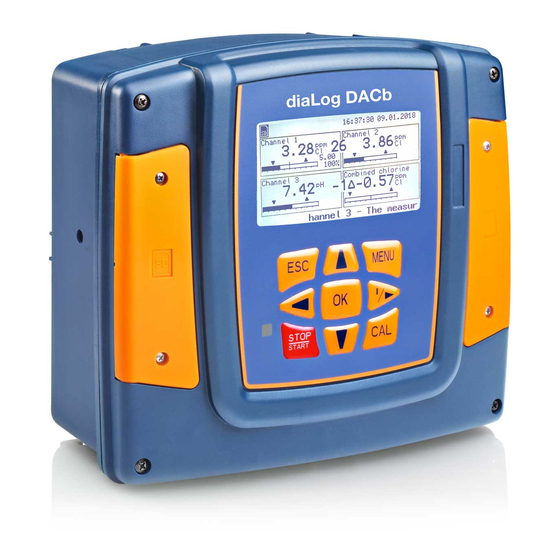
Operating concept Operating concept Display and keys A1035 Fig. 1: Operating cross (1) / Active keys are displayed in [black] in the display; inactive keys in [grey]. The following path is shown as an example: [Calibrate] ➨ [Slope] ➨ Continuous display ➨ ➨... - Page 10 Operating concept Illumination of the display In the event of an error with the status [ERROR], the backlight of the display changes from ‘white’ to ‘red’ . This makes it easier for the operator to react to an error. A2438 Fig.
- Page 11 Operating concept If you are using 3 measuring channels, you can use to display the overall view of the meas‐ uring channels as the fourth view, see . Kanal 1 Kanal 2 7.55 0.30 Kanal 3 A2441 Fig. 6: Example of a continuous display when used with 3 measuring channels (e.g. pH/chlorine/ ORP) and the display of all 3 measuring channels...
- Page 12 Operating concept Parameters in the adjustable menus Setting of the various parameters in the adjust‐ Cancelling the setting able menus process Pressing returns you to the menu without a value No time-controlled menu items being saved. The controller does not exit any menu items in a time-controlled manner, the controller remains in a menu item until this menu item is exited by the user.
-
Page 13: Functions Of The Keys
Operating concept Functions of the keys Tab. 2: Functions of the keys Function Confirmation in the setting menu: Confirms and saves the input values. Confirmation in the continuous display: Displays all information about saved errors and warnings. Back to the continuous display or to the start of the respective setting menu, in which you are currently located. -
Page 14: Changes The Set Operating Language
Operating concept Function Moves the cursor to the left. Changes the set operating language Simultaneously press the keys The controller changes to the menu for setting the operating language. ð Language Language German A1482 Fig. 7: Menu for setting the operating language Now using keys you can set the desired operating language Confirm your selection by pressing the key... -
Page 15: Acknowledge Fault Or Warning Message
Operating concept Acknowledge fault or warning message [Error] , the control is stopped, the backlight switches to red If the controller recognises an error lighting and the alarm relay is deactivated. You can access the next value to be set by pressing the key. -
Page 16: Measured Variables And Measuring Inputs
Operating concept Measured variables and measuring inputs Measured variable Measuring input Modul type pH (mV) mV/mA measuring input or mV/mV measuring input Temperature (mV) ORP (mV) pH (mA) mV/mA measuring input or mA/mA measuring input ORP (mA) mA general Bromine Chlorine Chlorine dioxide Chlorite... -
Page 17: Identity Code
, multi-parameter controller diaLog DACb Mounting type Wall-mounted Control panel-mounted Spare parts units Design with ProMinent logo without ProMinent logo Spare part, processor, complete Spare part, HMI, complete, with PM logo Spare part, HMI, complete, Pool design Operating voltage 4 24 V DC... - Page 18 Identity code DAC: DULCOMETER , multi-parameter controller diaLog DACb ® 3 Package 3: 2nd measurement + control, additionally 2 pumps, addition‐ ally 3 control inputs, replaces the D2Ca 4 Package 4: pH compensation for chlorine, only based on measured vari‐ able "VA"...
-
Page 19: A Complete Measuring Point May Comprise The Following
Identity code DAC: DULCOMETER , multi-parameter controller diaLog DACb ® Communication interface X none A Modbus RTU, terminal B Profibus DPV1, terminal E LAN with web server, connection via M12 C-coded G PROFINET (2xM12) ® Data logger 0 no data logger 1 with data logger (SD card interface + SD card + card reader) Hardware extension... -
Page 20: Safety And Responsibility
Safety and responsibility Safety and responsibility Labelling of Warning Infor‐ mation WARNING! Introduction Nature and source of the danger These operating instructions provide informa‐ Possible consequence: Fatal or very tion on the technical data and functions of the serious injuries. product. -
Page 21: General Safety Information
Safety and responsibility NOTICE! WARNING! Danger from hazardous substances! Nature and source of the danger Damage to the product or its surround‐ Possible consequence: Fatal or very ings. serious injuries. Measure to be taken to avoid this Please ensure when handling haz‐ danger. -
Page 22: Intended Use
Safety and responsibility Intended use WARNING! Operating faults! Intended use Possible consequence: Fatal or very The device is designed to measure and serious injuries. regulate liquid media. The labelling of the measured variables is indicated in – Ensure that the unit is only oper‐ the controller display and is absolutely ated by adequately qualified and binding. - Page 23 Safety and responsibility Disturbance resistance The device complies with disturbance resistance in accordance with EN 61326-1 and is intended for use in industrial electromagnetic environments and in residential areas. WARNING! Disturbance signal emission class A or B / Protection for radio reception The device complies with the disturb‐...
-
Page 24: User Qualification
Safety and responsibility User qualification WARNING! Danger of injury with inadequately qualified personnel The operator of the system / equipment is responsible for ensuring that the qualifications are fulfilled. If inadequately qualified personnel work on the unit or loiter in the hazard zone of the unit, this could result in dangers that could cause serious injuries and material damage. - Page 25 Safety and responsibility Training Definition Electrical technician An electrical technician is able to complete work on electrical systems and recognise and avoid possible dangers independently based on his technical training and experience as well as knowledge of pertinent standards and regulations. An electrical technician must be able to per‐ form the tasks assigned to him independently with the assistance of drawing documentation, parts lists, terminal and circuit diagrams.
-
Page 26: Functional Description
The DULCOMETER ® tion during commissioning. Multi-parameter Controller diaLog DACb is a controller platform manufactured by ProMinent. Temperature compensation for the pH and In the remainder of this document, the term fluoride measured variables. ‘controller’ is consistently used for the 22 operating languages. -
Page 27: Subsequent Extension Of Functions
Subsequent Extension of Functions Subsequent Extension of Functions Ä Chapter 3.4 ‘User User qualification, subsequent extension of functions: trained user, see qualification’ on page 24 Prerequisite: The hardware for channel 3 must be available in the controller. The data logger can be enabled without the need for extension of the hardware. - Page 28 Subsequent Extension of Functions Manual entry of the activation code: Press [Setup] . to select Press [Activation code] . to select Press [Manual input] . Select Press Use the 4 arrow keys to enter the activation code. Press [Double check] . to select Press The controller is now restarted.
-
Page 29: Functions To Backup The Controller's Setting Data
Functions to Backup the Controller's Setting Data Functions to Backup the Controller's Setting Data Ä Chapter 3.4 ‘User qualification’ User qualification, backup setting data: trained user, see on page 24 The following functions are available: Save unit configuration as a text file. Save unit configuration on an SD card. - Page 30 Functions to Backup the Controller's Setting Data Copying unit configuration onto the SD card: [Copy unit configuration file onto SD card] function is used for documentation or backup pur‐ poses. You can use this file to distribute a recurring unit configuration to different controllers. You can save the unit configuration set on one controller as a unit configuration file on the SD card.
- Page 31 Functions to Backup the Controller's Setting Data Uploading unit configuration file from the SD card Different identity codes If the identity codes of the source and destination controller differ, only the settings that both controllers have in common are carried over. If you have copied a configuration file to an SD card using the [Copy unit configuration file onto SD card] , then you can use this function to upload the unit configu‐...
-
Page 32: Assembly And Installation
Assembly and installation Assembly and installation User qualification, mechanical installation: Ä Chapter trained and qualified personnel Read-off and operating position 3.4 ‘User qualification’ on page 24 User qualification, electrical installation: Install the device in a favourable – Ä Chapter 3.4 ‘User Electrical technician position for reading and operating, qualification’... -
Page 33: Scope Of Supply
Assembly and installation Scope of supply Tab. 4: The following components are included as standard: Description Quantity Controller DAC Assembly material, complete, 2P Universal (set) Operating Manual General safety notes Mechanical Installation Fig. 9: Removing the wall bracket 7.2.1 Wall mounting Pull the two snap hooks (1) outwards The wall brackets snaps slightly Mounting materials (contained in the scope of... - Page 34 Assembly and installation A0492 Fig. 11: Fitting the wall bracket Hook the bottom of the housing (1) into the wall bracket Lightly press the housing at the top (2) against the wall bracket Then check that the housing is hooked in at the top and press down (3) until it audibly engages...
-
Page 35: Control Panel Installation
Assembly and installation 7.2.2 Control Panel Installation CAUTION! Dimensional variations Possible consequence: material damage – Photocopying the punched template can result in dimensional deviations – Use the dimensions shown in Fig. 13 and mark on the control panel CAUTION! Material thickness of control panel Possible consequence: material damage –... - Page 36 Assembly and installation A1179 Fig. 12: Order number for the DAC control panel fitting kit (included with the scope of supply): 1041095. Control panel 1 x foam rubber caulking strip ∅3 Galvanised steel retaining brackets (6 off) Galvanised PT cutting screws (6 off) Punched template...
- Page 37 Assembly and installation A1170 Fig. 13: The drawing is not true to scale and will not be revised as part of these operating instruc‐ tions. The drawing is for information only.
-
Page 38: Electrical Installation
Assembly and installation Determine the precise position of the device on the control panel using the drilling template Mark the corner points and drill (drill diameter 12 - 13 mm) Using a punching tool or jigsaw, match the opening to the punched template drawing Chamfer the cut edges and check whether the sealing surfaces are smooth for the caulking strip Otherwise the seal cannot be guaranteed. - Page 39 Assembly and installation Low voltage cables The low voltage cables must have a temperature resistance of ≧ 70 °C.
-
Page 40: Specification Of The Threaded Connectors
Assembly and installation 7.3.1 Specification of the threaded connectors A2461 Fig. 14: All dimensions in millimetres (mm). -
Page 41: Terminal Diagram
Assembly and installation 7.3.2 Terminal diagram The controller is supplied with terminal diagrams showing 1:1 assignment. Only one sensor per unit You can connect 2 sensors to the base module and 1 sensor to the extension unit. For example, you can connect a chlorine sensor and an ORP sensor to the base module and a pH sensor or an interference variable to the extension unit. - Page 42 Assembly and installation Connection of the transmitter DMTa A DMTa is connected to the controller as a 2 conductor transmitter: Terminal DACx, Channel 1: as per terminal diagram – Terminal DACx, Channel 2: as per terminal diagram – refer to: Ä ‘Terminal diagram for the base module (Channel 1 and 2) with assignment –...
- Page 43 Assembly and installation Klemmenanordnung Ausführung Wandgerät optional: Erweiterungsbaugruppe optional: RC-Schutzbeschaltung Sicherung Basisbaugruppe optional: Kommunikatonsmodul Schirmklemme Anschluss des Koaxialkabels an die Schirmklemme Messeingang Schirmklemme A2464 Fig. 15: Terminal layout...
- Page 44 Assembly and installation Terminal diagram for the base module (Channel 1 and 2) with assignment options Spannungsversorgung Digitaler Kontakteingang 1 Digitaler Kontakteingang 2 Digitaler Kontakteingang 3 Digitaler Kontakteingang 4 Externe Pumpe 1, heben (potenzialfrei) Externe Pumpe 2, senken (potenzialfrei) Normsignal-Ausgang 1 Normsignal-Ausgang 2 Magnetventil 1 (heben) Magnetventil 2 (senken)
- Page 45 Assembly and installation Terminal diagram for the extension unit (Channel 3) with assignment options Extension unit, Channel 3, there can only be one main measured variable, e.g. pH, connected to a unit. In addition, the mA signal of a magnetically inductive flow meter can be connected depending on the ID code.
- Page 46 Assembly and installation Normsignal-Ausgang3 0/4-20 mA Digitaler Kontakteingang Digitaler Kontakteingang Digitaler Kontakteingang Temperatur Potenzialausgleich Temperatur Normsignal-Eingang Stromquelle 2-Leiter-Normsignal-Eingang Sensor Externe Pumpe 3, heben (potenzialfrei) Externe Pumpe 4, senken (potenzialfrei) A1174 Fig. 17: Terminal diagram for the extension unit (Channel 3) with assignment options (Module C, optional)
- Page 47 Assembly and installation Terminal diagram with protective RC circuit (optional) RC-Schutzbeschaltung Extern Stromnetz A1180 Fig. 18: Terminal diagram with protective RC circuit (module D, optional). The RC unit is only per‐ mitted in conjunction with the 230 V design.
- Page 48 Assembly and installation Terminal diagram for the DAC "communication unit" Communication Communication communication Communication Plug M8x1 2 x plugs M8x1 (male) external ext. connector 2x socket M12x1 Female 4-pin external connector Socket M12x1 female (D-coded) 4-pin (D-coded) Switch alternative ext. WLAN router e.g.
- Page 49 Assembly and installation Service interfaces SD card connector Communication connector Display/Keyboard CAN internal Fan, 3-pin Battery Label, identification, unit A2466 Fig. 20: Service interfaces...
- Page 50 2-wire sensor, e.g. for chlorine, bromine or peracetic acid (PES). mA interface: for use with ProMinent 2-wire transmitters and sensors with 2-wire mA interface. Processing of active mA signals, type of connector: current source. Driver voltage: 24 V DC.
- Page 51 Assembly and installation Control line LiYY, 2 x 0.25 mm , Ø 4 mm, part number 725122 mV interface: For the direct connection of pH and ORP sensors Maximum cable length: 10 m Tab. 5: Sensor connection cable, coaxial, for terminal XE1/XE2 Description Part number Cable combination, coaxial, Ø...
- Page 52 Assembly and installation A module for the direct measurement of two pH values or two redox potentials or pH value and redox potential via a coaxial cable. For the direct connection of pH and ORP sensors Maximum cable length: 10 m Tab.
- Page 53 Assembly and installation Maximum cable length: 30 m, screened. Electrical data Parameter Value Cell constant: 0.005 1/cm ... 15 1/cm Measuring ranges dependent on the sensor type: Specific conductivity: 0.001 µS/cm ... 200 mS/cm Specific electrical resistance: 5 Ωcm ... 1000 MΩcm TOS (total dissolved solids): 0 ...
- Page 54 (PES), and pH and ORP via the pH transmitters, pHV1, part number 809126, and ORP, RHV1, part number 809127. For use with ProMinent 2-wire transmitters and sensors with 2-wire mA interface. Processing of active mA signals (type of connector: current source).
-
Page 55: Cable Cross-Sections And Cable End Sleeves
Assembly and installation 7.3.3 Cable Cross-Sections and Cable End Sleeves Minimum cross-sec‐ Maximum cross-sec‐ Stripped insulation tion tion length Without cable end 0.25 mm 1.5 mm sleeve Cable end sleeve 8 - 9 mm 0.20 mm 1.0 mm without insulation Cable end sleeve with 10 - 11 mm 0.20 mm... -
Page 56: Wall-Mounted And Control Panel Installation
Assembly and installation 7.3.4 Wall-mounted and control panel installation Seals and terminal diagram Select suitable seals to match the cable penetrations of the controller. Close open holes with blanking plugs. Only in this way can sufficient sealing be ensured. Moisture in the controller can lead to functional malfunctions. Observe the instructions on the enclosed terminal diagrams. -
Page 57: Switching Of Inductive Loads
Assembly and installation Slightly pull the upper part of the housing to the front and insert the top part of the housing in its parked position in the lower part of the housing. Large threaded connector (M 20 x 1.5). Medium threaded connector (M 16 x 1.5). -
Page 58: Connect The Sensors Electrically To The Controller
Assembly and installation The magnitude of the resistance R of the RC member is determined according to the fol‐ lowing equation: R=U/I A0835 (Where U= Voltage across the load and I Fig. 26: RC protective circuit for the relay con‐ current through the load) tacts The magnitude of the capacitor is determined... - Page 59 Assembly and installation 7.3.6.1 Connection of pH or ORP sensors via a coaxial cable NOTICE! Possible incorrect measurement due to poor electrical contact Only use this type of connector if you do not wish to use pre-assembled coaxial cables. Observe the following for this type of connection: Remove the black plastic layer from the inner coaxial cable.
- Page 60 Assembly and installation A0947 Fig. 28: Coaxial cable assembly When is potential equalisation used? Connect pH or ORP sensors via a coaxial cable, which relates to the Potential equalisation is used if the pH/ORP via mV connection type, pH/ORP measurement is interfered directly via the controller’s electrical ter‐...
- Page 61 Assembly and installation Switch the controller to a measurement with Sensor connection without potential equalisa‐ potential equalisation tion The sensor is connected to the controller, as marked in the terminal diagram. Do not remove NOTICE! the wire jumper in the controller. Wire jumper with connected potential equalisation Sensor connection with potential equalisation...
- Page 62 Assembly and installation Peculiarities when calibrating with potential equalisation When calibrating, immerse the potential equalisation in the respective buffer sol‐ ution, or use the calibration receptacle which forms part of the scope of delivery of the DGMa valve. This cali‐ bration receptacle incorporates an inte‐...
- Page 63 Assembly and installation 7.3.6.3 Connecting the conductive conductivity sensor NOTICE! The sensor must be dry Do not allow the conductivity sensor to come into contact with liquid. Only allow the conduc‐ tivity sensor to come into contact with liquid once the conductivity sensor has been con‐ nected, configured and calibrated.
- Page 64 Assembly and installation Selection of the connected sensor All of the sensor-dependent settings are reset to the [DEFAULT] values when changing the connected sensor. Sensor Connector Cell con‐ T-correction Max. temp. Measuring Measuring stant element range κ min range κ (°C) Cell con‐...
-
Page 65: Priming To Bleeding
Assembly and installation Sensor Connector Cell con‐ T-correction Max. temp. Measuring Measuring stant element range κ min range κ (°C) Cell con‐ (Unit) stant (1/cm) (Unit) LM1-TA Fixed cable 1.00 0.1 mS/cm 20 mS/cm 0.34 mm 5 m, shielded LMP1 DIN 4-pin 1.00 Pt100... -
Page 66: Commissioning
Commissioning Commissioning Switch-on behaviour during Ä Chapter User qualification: trained user, commissioning 3.4 ‘User qualification’ on page 24 Switching On - First Steps WARNING! Sensor run in periods Installation and function control This can result in hazardous incorrect Check that all the connections –... -
Page 67: Adjusting The Backlight And Contrast Of The Controller Display
Commissioning Adjusting the backlight and Should the controller operate as a one- contrast of the controller dis‐ way or two-way control? play Which control variables are there? What control parameters are necessary? [Setup] ➨ Continuous display ➨ ➨ [HOLD] ? What should the controller do in [Device setup] ➨... - Page 68 Commissioning [Sensor not dry] continues to be displayed despite the conductivity sensor having been dried, then you will have to wait some time until the controller has detected the sensor as dry. Once you have selected the sensor type, the prompt automatically appears asking whether the sensor parameters (zero point) have to be determined.
-
Page 69: Configuring Measured Variables
Configuring measured variables Configuring measured variables Ä Chapter 3.4 ‘User qualification’ on page 24 User qualification: trained user [Measurement] ➨ [Measurement] ➨ [Meas. channel 1] Continuous display ➨ ➨ [Measured variable] . ➨ Measuring channel settings This descriptions of [Channel 1] apply correspondingly to the settings in all other measuring channels. - Page 70 Configuring measured variables Measured variable Meaning Unit [mA general] [Freely selectable] [mA] [bar] [psi] [gal/h] [ppm] [%RH] [NTU] [Bromine] [ppm] Bromine [Chlorine] [ppm] Chlorine [Chlorine dioxide] [ppm] Chlorine dioxide [Chlorite] [ppm] Chlorite [Fluoride [mA]] [ppm] Fluoride [Oxygen] [ppm] Oxygen [Ozone] [ppm] Ozone [Peracetic acid]...
-
Page 71: Information On The Measured Variables
Configuring measured variables If you carry out the pH value measurement using potential equalisation, then you must adopt this approach when selecting the measured variable as a parameter. Information on the measured Glass break detection variables [ON] / [OFF] : Switches glass break detection of [ON] or [OFF] . -
Page 72: Measured Variable Ph [Ma]
Configuring measured variables 9.1.3 Measured variable pH [mA] Temperature compensation This function is used for compensation of the Measured variable pH [mA]: temperature influence on the measurement. ‘pH [mA]’ , i.e. pH If the measured variable This is only necessary with pH and fluoride measurement using a mA signal, is selected, measurement and when chlorine dioxide is then the possibility of sensor monitoring for... -
Page 73: Orp [Mv], Orp [Ma]
Configuring measured variables 9.1.4 ORP [mV], ORP [mA] 1. Into hypochlorous acid (HOCl) a strongly oxidising, efficient, anti-bacterial Measured variables ORP [mV], ORP [mA] agent that destroys most organisms very quickly. ‘ ORP [mV]’ or ‘ORP If the measured variable [mA]’... - Page 74 Configuring measured variables lated chlorine value does not change the effec‐ tive disinfection effect in the water. Calibration of the chlorine sensor Nevertheless, the aforementioned overdosing is avoided. The recognised reference method with active pH compensation DPD 1 (for free chlorine) is used as a compar‐ It is mandatory that you always cali‐...
-
Page 75: Measured Variable Fluoride
Configuring measured variables 9.1.6 Measured variable fluoride Temperature compensation Fluoride Measured Variable This function is used for compensation of the temperature influence on the measurement. When measuring fluoride as the measured vari‐ This is only necessary with pH and fluoride able, the sensor signal is converted into a 4 - measurement and when chlorine dioxide is 20 mA signal by a FPV1 or FP100V1 meas‐... -
Page 76: Hydrogen Peroxide
Configuring measured variables Temperature Measuring range: The temperature measurement is used only for Select the measuring range corresponding information or recording purposes, but not for to the measuring range of the measuring temperature compensation. Temperature com‐ transducer used. An incorrect measuring pensation is carried out in the sensor. -
Page 77: Conductive [Conductivity]
Configuring measured variables [conductivity] 9.1.10 Conductive Temperature compensation and reference temperature NOTICE! The sensor must be dry Do not allow the conductivity sensor to come into contact with liquid. Only allow the conduc‐ tivity sensor to come into contact with liquid once the conductivity sensor has been con‐ nected, configured and calibrated. - Page 78 Configuring measured variables The conductive conductivity measured at the fluid temperature is converted to the reference tem‐ [TREF] . perature Changing the reference temperature The temperature coefficient must be recalibrated if the reference temperature is changed. Adjustable process for temperature compensation [off] –...
-
Page 79: Temperature [Ma] , (As Main Measured Variable)
Configuring measured variables [mA] , (as 9.1.11 Temperature Measured variable: TDS value main measured variable) Symbol displayed in the controller's display: [TDS] (total dissolved solids) Measured variable temperature [mA], (as main measured variable): Unit of measurement: ppm (mg/l) ‘Temperature [mA]’ For the measured variable Physical variable: Total of all inorganic and use of a DMTa temperature measuring trans‐... - Page 80 Configuring measured variables Two channel version with two identical meas‐ ured variables If the measured variables of measuring channel 1 and measuring channel 2 are chosen identi‐ cally, then the menu item [Differential meas] appears in the [Measurement] menu. The [Differential meas] function is switched off "ex works".
-
Page 81: Calibration
Calibration Calibration User qualification: instructed user, Continuous display ➨ Menu ➨ [Calibration] ➨ . Ä Chapter 3.4 ‘User qualification’ on page 24 Continuous display ➨ Measuring channel settings Calibration This descriptions of [Channel 1] apply Please select channel correspondingly to the settings in all Channel 1 Chlorine other measuring channels. -
Page 82: Calibrating The Ph Sensor
Calibration 10.1 Calibrating the pH Sensor To ensure a high level of measuring accuracy, adjust the pH sensor at set time intervals. This cali‐ bration interval seriously depends on the application of the pH sensor and on the required measure‐ ment accuracy and reproducibility. - Page 83 Calibration Selecting the calibration process Buffer temperature dependencies Select the calibration process prior to initial cali‐ bration. This selection is saved until you select Buffer temperature a new process. At temperatures that differ by 25°C in 2-point calibration: This is the recom‐ the process, adjust the pH of the buffer mended calibration process because it solution by entering the reference...
-
Page 84: Selecting The Calibration Process For Ph
Calibration The sensor stability information displayed CAL pH [acceptable] , [good] and during calibration, [very good] , indicates to what extent the sensor Buffer 1: Buffer 2: signal fluctuates during calibration. At the start Calibr.param. for 25 °C of calibration, the waiting time for stabilisation Slope of the measured value is 30 seconds;... -
Page 85: 2-Point Calibration Of The Ph Sensor (Cal)
Buffer detection requirement The sensor needs to be removed – Buffer manufacturer ProMinent and refitted in the in-line probe Buffer value 1 pH 7 housing for calibration. Refer to Buffer value 2 pH 4... - Page 86 [Presetting]: select 2 buffers from the 4 possible buffer sets. During calibration, adhere to the selected order e.g. Buffer value 1: pH 7 and Buffer value 2: pH 4: Valid calibration values ProMinent (pH 4; 7; 9; 10). – ® Valid calibration: (default setting) Zero point -60mV…+60 mV...
- Page 87 Calibration Fig. 40: Display of the sensor stability achieved The range [acceptable / good / very good] is dis‐ Do not move the sensor cable played. during calibration as this can The black part of the horizontal bar lead to signal variations. ð...
- Page 88 Calibration Fig. 42: Display of the calibration result Sensor calibration in buffer 2 Sensor voltage Incorrect calibration Buffer temperature Stability An error message appears if the acceptable good result of the calibration lies out‐ side the specified tolerance limits. In this case the current Continue with <CAL>...
-
Page 89: Ph Sensor Calibration (Cal) With An External Sample (1-Point)
Calibration 10.1.3 pH sensor calibration (CAL) with an external sample (1-point) Measuring and control behaviour of the controller during calibration During calibration the actuating outputs are deactivated. Exception: a basic load or a manual control variable has been set. This remains active. The measured value output [standard signal output mA] is frozen, corresponding to its settings in the mA output menu. - Page 90 Calibration Correct sensor operation Correct measuring, control and metering is only possible if the sensor is working per‐ – fectly Refer to the sensor's operating instructions – Tab. 13: Valid calibration values Evaluation Zero point Slope Very good -30 mV … +30 mV 56 mV/pH …...
- Page 91 Calibration CAL pH 1) Take sample 2) Determine pH value pH value Change with <OK> continue with <CAL> A1022 Fig. 44: Instructions for determining the pH value using the [Sample] method Press Use the arrow keys to enter the pH value you have determined in the controller Press Accept the pH value by pressing All the values of the calibration result are shown in the display.
-
Page 92: Calibration Of The Ph Sensor (Cal) By [Data Input]
Calibration [Data Input] 10.1.4 Calibration of the pH Sensor (CAL) by Data input With the [Data input] calibration method, the known data of the sensor is entered in the con‐ troller. Calibration by data input is only as accurate and reliable as the method with which the data was determined. - Page 93 Calibration Tab. 14: Valid calibration values Evaluation Zero point Slope Good -30 mV … +30 mV -55 mV/pH ... -62 mV/pH Acceptable -60 mV ... -30 mV - 40 mV/pH ... - 65 mV/pH or +30 mV ... +60 mV Continuous display ➨...
- Page 94 Calibration Incorrect calibration An error message appears if the result of the calibration lies outside the specified tolerance limits. In this case the current calibration is not carried over. Check the prerequisites for calibration and eliminate the error. Then repeat calibration. Carry over the result of the calibration into the controller memory by pressing The controller shows the continuous display again and operates with the results of the ð...
-
Page 95: Calibrating The Orp Sensor
Calibration 10.2 Calibrating the ORP You can now start your chosen cali‐ ð Sensor bration process. 10.2.1 Selecting the calibration process for ORP 10.2.2 1-point calibration of ORP sensor (CAL) Selecting the calibration process There are two calibration processes available for calibrating the controller: Correct sensor operation 1-point (with buffer solution) - Page 96 Calibration Fig. 48: 1-point calibration of ORP sensor (CAL) Measuring and control behaviour Continue with of the controller during calibration During calibration the actuating outputs CAL ORP are deactivated. Exception: a basic load or a manual control variable has Immerse sensor in buffer been set.
-
Page 97: Calibration Data For Orp Sensor (Cal)
Calibration CAL ORP ORP sensor calibration Buffer value 165 mV The ORP sensor cannot be calibrated. Offset 0.0 mV Only an ‘OFFSET’ deviation of magni‐ tude ± 40 mV can be set and thus com‐ pensated. If the ORP sensor deviates by more than ±... -
Page 98: Calibrating The Fluoride Sensor
Calibration 10.3 Calibrating the Fluoride Continuous display ➨ Sensor CAL ORP 10.3.1 Selection of the calibration process for fluoride 0.0 mV Offset Last calibration 21.05.2013 14:59:56 To calibrate the controller there are two avail‐ able calibration processes: CAL setup Data input offset Calibration process 1 point 2 point... -
Page 99: 2-Point Fluoride Sensor Calibration (Cal)
Calibration 10.3.2 2-point fluoride sensor cal‐ ibration (CAL) Used calibration solution Dispose of the used calibration solu‐ Correct sensor operation tion. For more information: see calibra‐ tion solution safety data sheet. Correct measuring and metering is – only possible if the sensor is Two test containers with a calibration solution working perfectly are required for calibration. - Page 100 Calibration Fig. 56: Fluoride sensor calibration (CAL) Press the key in the continuous dis‐ play. Then press to change the ppm value Using the arrow keys select or press to continue with the calibra‐ [Two point calibration] tion Then press Then press CAL F - CAL F -...
-
Page 101: 1-Point Fluoride Sensor Calibration (Cal)
Calibration Incorrect calibration Measuring and control behaviour of the controller during calibration Should the result of the cal‐ ibration lie outside the During calibration the actuating outputs specified tolerance limits, are deactivated. Exception: a basic an error message appears. load or a manual control variable has In this case the current cali‐... - Page 102 Calibration Fig. 59: Fluoride sensor calibration (CAL) Press the key in the continuous dis‐ play. Then press to change the ppm value Using the arrow keys select or press to continue with the calibra‐ [Single point calibration] tion Then press Then press CAL F - Import the result of the calibration into...
-
Page 103: Calibration Of Amperometric Sensors
Calibration 10.4 Calibration of Ampero‐ metric Sensors Free chlorine or total available chlorine Calibration of the zero point is not nec‐ Calibration of Amperometric Sen‐ essary. sors Slope: Possible calibration in the range: The calibration procedure for ampero‐ 20% ... 300%. metric sensors is the same for all amperometric measured variables. -
Page 104: Calibrating The Slope
Calibration 10.4.2 Calibrating the slope Selecting the calibration process Continuous display ➨ CAUTION! CAL Cl Correct sensor operation / Run-in Last calibration 31.03. 2013 13:11:11 period Slope 100 % Damage to the product or its surround‐ Zero point 4.00 mA ings Slope calibration –... - Page 105 Calibration Measuring and control behaviour NOTICE! of the controller during calibration Prerequisites for correct calibration of During calibration the actuating outputs the sensor slope are deactivated. Exception: a basic – The reference method needed is load or a manual control variable has used, depending on the feed been set.
- Page 106 Calibration Fig. 62: Reference value calibration, the sensor Remove sample water directly at the measuring value is frozen here; now take the sample and point and determine the content of the feed [ppm] using an measure using DPD, for example chemical in the sample water in appropriate reference method (e.g.
-
Page 107: Calibration Of Zero Point
Calibration Permitted calibration range CAUTION! The permitted calibration range is 20 ... Correct sensor operation / Run-in 300% of the sensor's rated value. period Damage to the product or its surround‐ Example of a shallow slope: Blocking of ings the sensor membrane leads to a low slope (low slope = low sensor sensi‐... - Page 108 Calibration Fig. 64: Calibration of zero point Then press NOTICE! Prerequisites for a correct calibration of CAL Cl the sensor zero point Calibration successful – The run in period for the sensor has been adhered to Slope Zero point – There is permitted and constant flow at the in-line probe housing –...
-
Page 109: Calibrating The Oxygen Sensor
Calibration 10.5 Calibrating the oxygen sensor Sensor manufactur‐ 10.5.1 Specify the calibration er’s calibration specifica‐ interval tions When determining the cali‐ The calibration interval depends strongly on: bration interval, consider the application the sensor operating the installation location of the sensor instructions as they may specify additional and/or If you wish to calibrate a sensor for a special... - Page 110 Calibration 10.5.2.1 Calibration of the slope Fig. 67: Correction variable values in air Enter the current values for the correc‐ Press the CAL key in the continuous tion variables: Use OK to select the cor‐ display. rection variable. Use the arrow keys to enter the values.
- Page 111 Calibration Fig. 71: Calibrating the slope using a reference The display appears as follows if cali‐ measurement in water bration is unsuccessful: Use OK to select the calibration CAL O2 process: Calibrate the slope using a ref‐ erence measurement in water. Calibration not possible Slope The display appears as follows:...
- Page 112 Calibration Fig. 76: Unsuccessful calibration CAL O2 Use CAL to end Reference value Press ESC to cancel Check the sensor and installation once 07.51 ppm again and repeat the calibration proce‐ dure. Range: 0.00 ... 24.00 ppm A2858 Fig. 74: Reference value Continue with CAL.
- Page 113 Calibration 10.5.2.3 Calibration of the zero Fig. 78: Zero point point Position the sensor in an oxygen-free Calibration of the zero point is only needed for environment e.g. in water with a slight precise measurements at the lower end of the excess of sodium hydrogen sulfite and measuring range (<...
-
Page 114: Measured Value [Ma General] Calibration
Calibration 10.6 Measured value [mA gen‐ You may need a manual measuring instrument eral] calibration for the conductivity measured variable. This manual instrument should measure and display sufficiently accurately to guarantee successful calibration. Measured value [mA general] cal‐ Press in the continuous display. ibration The measured value [mA general] Use the arrow keys to select... -
Page 115: Calibrating Conductive Conductivity
Calibration 10.8 Calibrating conductive 10.8.1 Calibrating conductive conductivity, sensor conductivity parameter adjustment Measuring and control behaviour NOTICE! of the controller during calibration The sensor must be dry During calibration the actuating outputs are deactivated. Exception: a basic Do not allow the conductivity sensor to load or a manual control variable has come into contact with liquid. - Page 116 Calibration [Sensor not dry] continues to be displayed despite the conductivity sensor having been dried, then you will have to wait some time until the controller has detected the sensor as dry. Once you have selected the sensor type, the prompt automatically appears asking whether the sensor parameters (zero point) have to be determined.
-
Page 117: Calibrating Conductive Conductivity, Cell Constant
Calibration 10.8.2 Calibrating conductive conductivity, cell constant Prerequisite for calibration. The conductivity sensor is connected. The conductivity sensor is in a conductivity calibration solution, the conductivity of which is known. Material Order number Conductivity calibration solution, 1413 μS/cm, 250 ml. 1027655 Conductivity calibration solution, 1413 μS/cm, 1000 ml. - Page 118 Calibration Incorrect calibration Cell constant, valid range: 0.005 ... 15 1/cm An error message appears if the result of the calibration lies outside the speci‐ fied tolerance limits. In this case, the current calibration is not carried over. Check the prerequisites for calibration and eliminate the error. Then repeat cali‐ bration.
-
Page 119: Calibrating Conductive Conductivity, Temperature Coefficient
Calibration 10.8.3 Calibrating conductive [Sensor signal stability] bar ð conductivity, temperature moves now to the right. coefficient [low] is displayed, then repeat the Prerequisite for calibration. The conductivity process at a temperature of 1 ... 2 [low] continues to be sensor is connected. -
Page 120: Calibrating Temperature
Calibration 10.9 Calibrating temperature You may need a manual measuring instrument for the temperature measured variable. This manual instrument should measure and display sufficiently accurately to guarantee successful Measuring and control behaviour calibration. of the controller during calibration Press in the continuous display. During calibration the actuating outputs are deactivated. -
Page 121: Setting The [Control]
[Control] Setting the [Control] Setting the Ä Chapter 3.4 ‘User qualification’ on page 24 User qualification: trained user, [Control] ➨ [Control] Continuous display ➨ ➨ Measuring channel settings This descriptions of [Channel 1] apply correspondingly to the settings in all other measuring channels. - Page 122 [Control] Setting the Control Channel 1 parameter set 1 Disturbance variables metering lock Parameter switch A0940 Fig. 81: Continuous display ➨ ➨ [Control] ➨ [Control] pH [mV] 3.1.9 Channel 1 parameter set 1 Type PID control System response normal Setpoint 7.00 pH 1.54 pH Add.
- Page 123 [Control] Setting the Parameter level 1 Function Parameter The adjustable range of the Ti-value is specified by the device. The adjustable range of the Td-value is specified by the device. [Additive basic The adjustable range of the additive basic load is load] specified by the device.
- Page 124 [Control] Setting the Eff. direction of the [Control], bidirectional or monodirectional [control] based on various features. You can vary the [control] operates in two possible directions (increase AND decrease meas‐ Function: A bidirectional ured value). Application: Acidic or alkaline waste water is produced alternately in a neutralisation process in an industrial waste water system.
- Page 125 [Control] Setting the Negative Positive Deviation Deviation to the setpoint to the setpoint Upper Setpoint (pH 7.3) Lower Setpoint (pH 6.7) Time Deadzone Positive No control takes‘s place here control output Time Negative control output A1475 Fig. 84: Control type PID bidirectional, with dead zone...
- Page 126 [Control] Setting the [control] operates in only one of two possible directions (increase OR Function: A monodirectional decrease measured value). Application: This affects, for example, a disinfection process, in which chlorine is added to water. The incoming water has a chlorine concentration of 0 ppm and is to be adjusted to 0.5 ppm by the addition of sodium-calcium hypochlorite.
-
Page 127: Control Parameter [Type]
[Control] Setting the Negative deviation Setpoint Time Time Positive control variable A1472 Fig. 86: Control type PID monodirectional, pH-increasing direction Adjustable parameters in the [Control] menu P controller: Make the following selection in the Control This controller type is used with an integrating [Batch Neutralisation] ). -
Page 128: Control Parameter [System Response]
[Control] Setting the [dead zone] should have the effect of pre‐ PI controller: venting the control path from starting to oscil‐ This controller type is used with a non-inte‐ late. If the measured value lies within both the grating control path (e.g. flow neutralisations). setpoints, then no control of the actuators takes Here excess fluctuation must be avoided. -
Page 129: Control Parameter [Xp]
[Control] Setting the 11.4 Control parameter [xp] The xp value is the controller amplification factor. The xp value relates to the measuring range end of a controller and is entered as an absolute value. For pH for example xp=1.5. For measured variables such as chlorine, the sensor measuring range is selected. The sensor measuring range corresponds to the measuring range end. -
Page 130: Control Parameter [Ti]
[Control] Setting the 11.5 Control parameter [Ti] 11.8 Control parameter [Checkout time] [Ti] is the integral time of the I-con‐ The time troller (integral controller) in seconds. The time [checkout time] should prevent overdosing [Ti] defines the time integration of the control as a result of a malfunction. - Page 131 [Control] Setting the Additive and multiplicative feedforward control Applicational example of additive interference variable Alongside information relating to the actual measured variable, e.g. the chlorine concentra‐ If the addition of a chemical is largely only tion, the interference variable is a further dependent on the flow (proportional depend‐...
- Page 132 [Control] Setting the [Menu] , [Control] , [Interference variable] , [On] , [Signal source] = [mA input 2] [Effect] : [additive] [Assignment] : [0…20 mA] or [4…20 mA] [Nominal value] : enter the maximum expected analog current here, e.g. 18 mA...
-
Page 133: Remote Setpoint Via A 0/4
[Control] Setting the Multiplicative interference variable The multiplicative interference variable can influence the control variable of the setpoint controller over the entire control range proportionately to the interference variable. This corresponds to a pro‐ portionality factor of 0.00 = 0% and 1.00 = 100 %, including all intermediate values. Tab. - Page 134 [Control] Setting the Remote setpoint 3.3.1 Function Signal source mA output 1 Range 4 ... 20 mA 4mA = 1.00 ppm 20 mA 1.00 ppm Assignment Channel 1 A1477 Fig. 88: Remote setpoint via a 0/4 ... 20 mA analogue signal Description Factory setting Setting options...
-
Page 135: Parameter Switch] Via The Digital Input Or [Timer]
[Control] Setting the 11.12 [Parameter switch] via Application example: the digital input or In a process control system, two different pH [Timer] setpoints with different control parameters must be reached and maintained. The system is con‐ [Control] Continuous display ➨ ➨... - Page 136 [Control] Setting the Event controlled Event 3.5.1.1 Function Signal source Digital input 1 Status active opened Switch off delay Assignment Channel 1 A1478 Fig. 89: Event controlled Description Factory setting Adjustment Options Function On/Off Signal source Digital input 2 Digital input 2, digital input 5 Status Active opened Active opened, Active closed...
- Page 137 [Control] Setting the Timer 1 3.5.2.1.1 Function On time 03:00 Off time 03:01 Monday Tuesday Wednesday Thursday Friday Saturday Sunday A1480 Fig. 91: Example: Timer 1...
-
Page 138: Setting The [Limit Values]
[Limit values] Setting the [Limit values] Setting the Ä Chapter 3.4 ‘User qualification’ on page 24 User qualification: trained user, see [Limit values] ➨ [Limit values] Continuous display ➨ ➨ Measuring channel settings This descriptions of [Channel 1] apply correspondingly to the settings in all other measuring channels. - Page 139 [Limit values] Setting the The limit values are values that can be set within the measuring range of a measured variable. For [1] can be set for exceeding, i.e. the measured value is greater than each measuring channel a Limit [2] can be set for undershooting, i.e.
- Page 140 [Limit values] Setting the If the relays are defined as limit value relays, when a limit value transgression occurs they also switch to the alarm relay. Different switch on-delays (∆t On) and Switch off delays (∆t Off) can be set for the limit value relays [Limit 1] and [Limit 2] .
-
Page 141: Setting Limit Values Channel 1
[Limit values] Setting the 12.2 Setting limit values channel 1 [Limit values] ➨ [Limit values] ➨ Continuous display ➨ ➨ [Limit value channel 1] ➨ [Limit value channel 1] Limit values ch. 1 4.1.5 Limit value 1 Limit value 2 System response / hysteresis A1012 Fig. - Page 142 [Limit values] Setting the Limit 2 4.1.3.1 High limit Function Value 9.00 pH ON delay OFF delay No relays assigned! Please assign in <Relays> menu. A1166 Fig. 96: Setting [Limit 2]...
-
Page 143: Setting [System Response]
[Limit values] Setting the 12.2.3 Setting [System response] [Limit values] ➨ [Limit values] ➨ Continuous display ➨ ➨ [Limit value channel 1] ➨ [Limit value channel 1] ➨ [System response] ➨ [System response] System response 4.1.5.1 Hysteresis Error messages Message delay Control Stop with fault A1167 Fig. -
Page 144: Setting The [Pumps]
[Pumps] Setting the [Pumps] Setting the 13.1 Setting [Pump 1] User qualification: trained user, see Ä Chapter 3.4 ‘User qualification’ on page 24 CAUTION! [Pumps] ➨ Continuous display ➨ ➨ [Pumps] Refer to the operating manual for the pump Possibility of damaging the pump. Measuring channel settings Faults in the process. - Page 145 [Pumps] Setting the [Pumps] ➨ Continuous display ➨ ➨ [Pumps] ➨ [Pump 1 channel 1] ➨ Pump 1 Function Decrease value Max. stroke rate Assignment Channel 1 A1068 Fig. 99: Setting [Pump 1] Use the keys to select the menu and confirm with The relevant setting menu appears.
- Page 146 [Pumps] Setting the Parameter Settable function [Function] Set the pump to: [Increase value] [Decrease value] [Off] [Max. stroke rate] The maximum stroke rate can be set freely between 0 ... 500 /min. The factory setting is 180/min [Assignment] Assign the pump to the relevant measuring channel: Channel 1: Pump 1 and pump 2 Channel 2: Pump 3 and pump 4...
-
Page 147: Setting The [Relays]
[Relays] Setting the [Relays] Setting the Ä Chapter 3.4 ‘User qualification’ on page 24 User qualification: trained user, see [Relays] ➨ [Relays] Continuous display ➨ ➨ Measuring channel settings This descriptions of [Channel 1] apply correspondingly to the settings in all other measuring channels. - Page 148 [Relays] Setting the 14.1 Setting Relay 1 [Relays] ➨ Continuous display ➨ ➨ [Relays] ➨ [Relay 1] ➨ Relay 1 6.1.1 Function Limit 1 Assignment Channel 1 A1070 Fig. 101: Setting Relay 1 Use the keys to select the respective menu and confirm with The relevant setting menu appears.
- Page 149 [Relays] Setting the Tab. 16: Settable parameters of Relay 1 and Relay 2 Parameter Settable function Relay state [Function] Set relay as: [Off] [Limit value 1] Active closed (default). [Limit value 2] [Limit value 1 <Control variable>] Active opened. [Limit value 2 <Control variable>] [Cycle] [Pulse length (PWM)] [Assignment]...
-
Page 150: Function Description [Off]
[Relays] Setting the 14.1.3 Function description [Limit 1] or [Limit 2] Changeable scope of the menus [Relay 1] and/or [Relay 2] can be operated as The number of adjustable parameters limit value relays. The limit values can be set in may differ depending on the type and Ä... -
Page 151: Functional Description Of [Pulse Length (Pwm)]
[Relays] Setting the CAUTION! [Cycle] is reset when there is no supply voltage Possible consequence: slight or minor injuries. Material damage. – Configure the power supply so that it cannot be interrupted – With critical processes, practically address the possible failure of the timer when designing your application Cycle Timer r elay... -
Page 152: Setting [Digital Inputs]
[digital inputs] Setting [digital inputs] Setting Ä Chapter 3.4 ‘User qualification’ on page 24 User qualification: trained user, see [Digital inputs] ➨ [Digital Inputs] Continuous display ➨ ➨ Measuring channel settings This descriptions of [Channel 1] apply correspondingly to the settings in all other measuring channels. - Page 153 [digital inputs] Setting Digital input 1 7.1.1 Function Pause Status Active opened Switch off delay 10 s Alarm Assignment Channel 1 Fig. 105: Setting [Digital input 1] Tab. 18: Pause Parameter Adjustment range Function Pause / Off / Pause Hold Status Active open / Active closed Switch off delay...
- Page 154 [digital inputs] Setting Setting [Digital input 3] Tab. 20: Level of storage tank 1 Parameter Adjustment range Function Off / Pause Hold / Pause / Level of storage tank 1 Status Active open / Active closed Switch off delay 0 ... 1800 s Assignment Channel 1, channel 2 Setting [Digital input 4]...
-
Page 155: Setting The [Ma Outputs]
[mA outputs] Setting the [mA outputs] Setting the Ä Chapter 3.4 ‘User qualification’ on page 24 User qualification: trained user, [mA outputs] ➨ [mA outputs] Continuous display ➨ ➨ Settings for [Channel 2] and [Channel 3] The 2-channel version of the controller has 2 mA outputs and the 3-channel version has 3 mA outputs. - Page 156 [mA outputs] Setting the mA outputs mA output 1 mA output 2 mA output 3 Fig. 106: Setting the [mA outputs]. Optional mA outputs The menu items for the optional mA outputs have the same setting options as the [mA output 1] menu item. A separate description is not provided.
-
Page 157: Setting The [Ma Outputs]
[mA outputs] Setting the [mA outputs] 16.1 Setting the [mA outputs] ➨ [mA outputs] ➨ [mA output 1] Continuous display ➨ ➨ [Function] Set function mA-output 1 Function Measured value Assignment Channel 1 Output range 0 ... 20 mA Current on error 23 mA 0 mA -1,45 pH... - Page 158 [mA outputs] Setting the [Function ] Adjustable value Adjustable ranges or counter values [Error current] [Off] 23 mA [0 mA] - 100% ... + 100% [20 mA] - 100% ... + 100% [Filtering] [high] [average] [weak] [Response with Pause [None] Hold] The mA output changes with the measured value [Fixed]...
-
Page 159: Function: Data Logger
Function: Data logger Function: Data logger Data backup / limited service life Access flap to SD card slot There is a possibility of loss of data with Always keep the access flap to the SD all types of data storage. Data loss can card slot closed during operation. -
Page 160: Configuring Log Books
Function: Data logger If the SD card is in the controller, this is dis‐ The calibration log book stores all calibrations played on the display in the top-left corner by of measured variables with a time stamp. [SD] symbol. If the SD card is 80% full, then Press in the continuous display this level also appears on the screen as... -
Page 161: Using The [Error Log Book]
Function: Data logger Use the arrow keys to move the cursor Use the arrow keys to browse through the [Record] entries in the calibration log book. Press return to the continuous display. Press The activation symbol (tick) ð [error log book] 17.2.2 Using the appears in the selection boxes. -
Page 162: Using The [Data Log Book] (Optional)
Function: Data logger Fig. 113: Reading the [Error log book] Use the arrow keys to select [Error log book] Use the arrow keys to browse through the Press entries in the error log book. Press to return to the continuous display. Use the arrow keys to move the cursor [Record] [Data log book]... - Page 163 Function: Data logger Fig. 117: [One file per day] unchecked Configuration 9.1.4.1 If you wish to specify a file name, then Measured value channel 1 [File name] and place the cursor on Temperature channel 1 press Control variable channel 1 Measured value channel 2 [New] appears.
- Page 164 Function: Data logger the internal memory is backed up to the SD card. This can take up to 20 minutes if 24 hours of data has been recorded. The green LED on the SD card reader flashes red/orange during this time.
-
Page 165: Diagnostics
[Diagnostics] [Diagnostics] 18.1.1 Displaying the User qualification: instructed user [Calibration Log Book] Ä Chapter 3.4 ‘User qualification’ on page 24 The data on the sensor calibrations success‐ fully completed are stored in the internal Continuous display ➨ ➨ [Calibration log book] . Up to 30 calibrations can [Diagnostics] ➨... -
Page 166: Displaying [Simulation]
[Diagnostics] 18.3 Display [Error log book] Deleting entries in the [Device information] You can also delete entries in the Error log book. Deleting the entries does not affect the Continuous display ➨ ➨ errors stored in the controller. [Diagnostics] ➨ [Diagnostics] ➨... -
Page 167: Error Messages And Warning Alerts
[Diagnostics] 18.4 Error messages and warning alerts 18.4.1 Error messages Tab. 23: Error messages Error Error message text Cause Remedy The mV input Coaxial cable connec‐ Check that the coaxial cable connec‐ voltage is too low. tion disconnected. tion is fitted correctly and re-connect. Check the coaxial cable connection for corrosion and moisture and replace with a new cable, if necessary. - Page 168 [Diagnostics] Error Error message text Cause Remedy No sensor detected, Measuring cable con‐ Check the correct connection of the please check the nection disconnected. measuring cable connection. connection. Connect the sensor correctly. No sensor is con‐ nected. Cable faulty or not con‐ nected.
- Page 169 [Diagnostics] Error Error message text Cause Remedy A limit value error The measured value Check whether the choice of the limit still exists after the lies above the limit value matches the application and delay time has value for a period adjust the limit value if necessary.
- Page 170 [Diagnostics] Error Error message text Cause Remedy The mA input supply The sensor input of Check the polarity against the terminal is overloaded. Channel 1 or 2 is used diagram. in 2-wire connection Make sure that the two wires do not mode, e.g.
- Page 171 [Diagnostics] Error Error message text Cause Remedy The correction vari‐ One or more correction Check the correction variable and all able is faulty. variables have been connected components. incorrectly entered and/or the correction variable has been incorrectly recorded. The external power The external power Return the external power supply to its supply is faulty.
-
Page 172: Warning Messages
[Diagnostics] 18.4.2 Warning messages Tab. 24: Warning messages Warning message Cause Remedy text The limit value was The measured value is Check whether the choice of the limit undershot below the limit value value matches the application and adjust if necessary. Check the design of the actuator: has too small an actuator been selected? Check the concentration of the feed... - Page 173 [Diagnostics] Warning message Cause Remedy text The battery needs The battery has a Replace the battery or inform Service. to be replaced service life of about 10 Battery BR 2032, Part no. 732829. years, but this can be reduced by environ‐ mental factors Check the time The time has changed...
-
Page 174: Help Texts
[Diagnostics] 18.5 Help texts Content of the help Cause Remedy texts The DPD value is too If the calculated reference value (e.g. Increase the concentration of small, DPD value > DPD1) for calibrating a sensor is less the chemical to be measured MRS + 2 % than 2 % of the measuring range, then in the process/sample water... - Page 175 [Diagnostics]...
-
Page 176: Measuring Range And Technical Data
Measuring range and technical data Measuring range and technical data 19.1 Measuring range/Measured value Tab. 25: Measuring range/Measured value Parameter Measuring range/Measured value Measuring range connector type mV: pH: 0.00 ... 14.00 ORP voltage: -1500 ... +1500 mV Connector type mA (amperometric Chlorine measured variables, measuring ranges Chlorine dioxide... -
Page 177: Technical Data
Measuring range and technical data Parameter Measuring range/Measured value Specific conductivity: 0.001 µS/cm ... 200 mS/cm Specific electrical resistance: 5 Ωcm ... 1000 MΩcm TOS (total dissolved solids): 0 ... 9999 ppm (mg/l) SAL (salinity): 0.0 ... 70.0 ‰ (g/kg) 19.2 Technical data Tab. - Page 178 Measuring range and technical data Description Technical data 2 x 0/4 ... 20 mA Alarm relay: 250 V ~5 A, 1000 VA, type of contact: changeover con‐ tact. No inductive loads, use a protective RC circuit (optional) with inductive loads. Limit value relay: 250 V ~5 A, 1000 VA, type of contact: changeover con‐...
-
Page 179: Spare Parts And Accessories
Spare Parts and Accessories Spare Parts and Accessories 20.1 Spare parts A1266 Fig. 124: Spare parts Pos. Spare parts Order number with 230 V device: micro-fuse 5x20 T 1.6 A 732411 with 24 V device: micro-fuse 5x20 T 3.15 A 732414 Fan housing with speed signal, 5 V DC, 50x50x10 mm 733328... -
Page 180: Replacement Of Spare Parts Units
Spare Parts and Accessories Pos. Spare parts Order number SD card, industrial quality 1030506 SN6 socket 1036885 Cable threaded connector M16x1.5 1005874 Cable threaded connector M20x1.5 1005517 Counter nut, M20x1.5 1021016 The spare parts units are ordered as identity code features and replaced and configured as described. - Page 181 Spare Parts and Accessories Disconnect the controller from the mains power supply. Loosen the 4 screws on the housing upper part (2) and remove the upper part of the housing. Place or suspend the housing upper part near the controller. If fitted: loosen the strain relief (1 and 5).
- Page 182 Spare Parts and Accessories Replacing the housing lower part Back up all parameters Where possible, back up all the controller's set parameters on the SD card before replacing the housing lower part (6). You can then use this data backup when the unit is recommis‐ sioned to upload all the old parameters to the new controller.
-
Page 183: Replacing A Fan
Using an appropriate tool, such as pointed pliers (e.g. DIN EN 60900; VDE 0682-201), loosen the electrical plug-in connector (1). Remove the fan (2). Insert the new fan (2). The ProMinent lettering faces you. Make sure that the two fixing hooks slot in properly. ð... -
Page 184: Accessories
Spare Parts and Accessories 20.4 Accessories Accessories Order number Coaxial cable combination 0.8 m, pre-assembled 1024105 Coaxial cable combination 2 m-SN6 - pre-assembled 1024106 Coaxial cable combination 5 m-SN6 - pre-assembled 1024107 SN6 socket, retrofitting 1036885 Installation kit - DAC - control panel installation 1041095... -
Page 185: Disposal Of Used Parts
To do so, remove all traces of haz‐ ardous substances. Refer to the Material Safety Data Sheet for your feed chemical. A current Declaration of Decontamination is available to download on the ProMinent web‐ In accordance with the European Directive site. 2012/19/EU on waste electrical and electronic equipment, this device features the symbol showing a waste bin with a line through it. - Page 186 Standards complied with and Declaration of Conformity Standards complied with and Declaration of Conformity The Declaration of Conformity for the controller is available to download on our homepage. EN 61010-1 Safety requirements for electrical equipment for measurement, control and labo‐ ratory use –...
- Page 187 Index Index 1, 2, 3 ... Configuration of the data log book ..163 Configuring the log books ... 160 [Relay timer] ....150 Connection of the chlorine sensor with 32 GB .
- Page 188 Index Industrial and process water treatment . . . 26 Question: Are there disadvantages with pH calibration with an external sample? ..90 Question: How can I bleed the hydraulic installation? ....65 Key Lock .
- Page 189 Index Question: What should I consider when Remove and refit the pH sensor in the in- connecting passive monitors? ..155 line probe housing ....85 Question: What sort of applications are Run in periods .
- Page 190 Index User qualification ....24 Waste water treatment ... . . 26 Validity of the activation code ..27 Zero point calibration .
- Page 192 ProMinent GmbH Im Schuhmachergewann 5 - 11 69123 Heidelberg Telephone: +49 6221 842-0 Fax: +49 6221 842-419 Email: info@prominent.com Internet: www.prominent.com 983369, 3, en_GB © 2019...
Need help?
Do you have a question about the DULCOMETER diaLog DACb and is the answer not in the manual?
Questions and answers
How do I calibrate measuring channel
To calibrate a measuring channel on a ProMinent diaLog DACb:
1. Select the channel to be calibrated (e.g., Channel 1: Chlorine).
2. Access the [Calibration] menu from the continuous display.
3. Follow the on-screen instructions to perform the calibration.
4. Adjust the value using the appropriate buttons if prompted.
5. Import the calibration result into the controller memory by pressing the confirmation button.
6. The controller will return to the continuous display and use the new calibration values.
If calibration values are outside specified limits, an error message appears, and the calibration is not saved. In that case, check conditions, correct any issues, and repeat the calibration. Each measuring channel must be calibrated separately.
This answer is automatically generated