Table of Contents
Advertisement
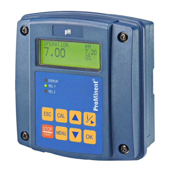
Assembly and operating instructions
DULCOMETER
, Compact Controller
®
Measured variable: conductive conductivity
EN
A1700
Please carefully read these operating instructions before use. · Do not discard.
The operator shall be liable for any damage caused by installation or operating errors.
The latest version of the operating instructions are available on our homepage.
Part no.: 985092
BA DM 209 08/15 EN
Advertisement
Table of Contents

Related Manuals for ProMinent DULCOMETER Compact


Summary of Contents for ProMinent DULCOMETER Compact
- Page 1 Assembly and operating instructions DULCOMETER , Compact Controller ® Measured variable: conductive conductivity A1700 Please carefully read these operating instructions before use. · Do not discard. The operator shall be liable for any damage caused by installation or operating errors. The latest version of the operating instructions are available on our homepage.
- Page 2 Supplemental instructions General non-discriminatory approach In order to make it easier to read, this document uses the male form in grammat‐ ical structures but with an implied neutral sense. It is aimed equally at both men and women. We kindly ask female readers for their understanding in this simplification of the text.
-
Page 3: Table Of Contents
Table of contents Table of contents Identity code......................6 Introduction......................8 2.1 Measured variables..................8 Safety and Responsibility..................10 3.1 Explanation of the safety information............10 3.2 General Safety Information................11 3.3 Intended Use....................13 3.4 Users' qualifications..................14 Functional description................... 16 Assembly and installation.................. - Page 4 Table of contents 8.6 Password...................... 54 Operating menus ....................55 [CAL] the conductivity sensor ............ 55 9.1 Calibrating 9.1.1 Calibration of the cell constant..............57 9.1.2 Calibration of the temperature coefficient..........60 [LIMITS] ................ 63 9.2 Setting limit values [CONTROL] ..............66 9.3 Setting the control [INPUT] .................
- Page 5 Table of contents Replacing spare part units ................. 102 15.1 Replacing the top part of the housing............102 15.2 Replacing the lower part of the housing (wall/tube retaining bracket)..104 15.3 Replacing the lower part of the housing (control panel installation)..106 Standards complied with and Declaration of Conformity........
-
Page 6: Identity Code
Mounting type Spare part units Wall/pipe mounting IP 67 With fitting kit for control panel mounting IP 54 Design With ProMinent ® logo E1 Spare part unit, controller housing lower part (processor/PCB), fully assembled E2 Spare part unit, controller housing top part (processor/PCB), fully... - Page 7 Identity code DCCa DULCOMETER Compact, ® English Lithuanian Spanish Latvian Italian Dutch French Polish Finish Portuguese Bulgarian Romanian Chinese Swedish Czech Slovakian Greek Slovenian Hungarian Russian Japanese Thai...
-
Page 8: Introduction
Introduction Introduction Data and functions Measured variable: conductive conduc‐ [ConC] tivity These operating instructions describe the technical data and functions of the Symbol displayed in the controller's dis‐ [ConC] play: DULCOMETER Compact Controller, ® measured variable: conductive conduc‐ Units of measurement: μS/cm, mS/cm , S/ tivity. - Page 9 Introduction Measured variable: TDS value Measured variable: Salinity (SAL) Symbol displayed in the controller's dis‐ Symbol displayed in the controller's dis‐ [TDS] (total dissolved solids) [SAL] units: ‰ (g/kg) play: play: Unit of measurement: ppm (mg/l) Physical variable: Mass of salts in a kg of water given in PSU (practical salinity Physical variable: Total of all inorganic units).
-
Page 10: Safety And Responsibility
Safety and Responsibility Safety and Responsibility Explanation of the safety information WARNING! Introduction Nature and source of the danger These operating instructions provide infor‐ Possible consequence: Fatal or very mation on the technical data and functions serious injuries. of the product. These operating instruc‐ Measure to be taken to avoid this tions provide detailed safety information danger... -
Page 11: General Safety Information
Safety and Responsibility General Safety Information NOTICE! Nature and source of the danger WARNING! Damage to the product or its sur‐ Live parts! roundings Possible consequence: Fatal or very Measure to be taken to avoid this serious injuries danger – Measure: Disconnect the mains Note! power supply prior to opening the... - Page 12 Safety and Responsibility NOTICE! WARNING! Operating errors! Correct and proper use Possible consequence: Fatal or very Damage to the product or its sur‐ serious injuries roundings – The unit should only be operated – The unit is not intended to by adequately qualified and tech‐...
-
Page 13: Intended Use
Safety and Responsibility Intended Use NOTICE! Correct sensor operation NOTICE! Damage to the product or its sur‐ Intended Use roundings The device is designed to measure – Correct measuring and dosing is and regulate liquid media. The desig‐ only possible if the sensor is nated measured variable is detailed working perfectly on the controller and is absolutely... -
Page 14: Users' Qualifications
Trained user A trained user is a person who fulfils the requirements made of an instructed person and who has also received additional training specific to the system from ProMinent or another authorised distribution partner. Trained qualified per‐ A qualified employee is deemed to be a person who is able to sonnel assess the tasks assigned to him and recognize possible haz‐... - Page 15 Customer Service department refers to service technicians, department who have received proven training and have been authorised by ProMinent to work on the system. Note for the system operator The pertinent accident prevention regulations, as well as all other generally acknowl‐...
-
Page 16: Functional Description
Functional description Functional description Brief functional description Digital input to switch off the controller or to process a sample water limit The controller for the measured variable contact by remote control conductive conductivity provides the basic Temperature sensor input (Pt100 or functions for water treatment applications. -
Page 17: Assembly And Installation
Assembly and installation Assembly and installation User qualification, mechanical instal‐ lation: trained qualified personnel, see NOTICE! Ä Chapter 3.4 ‘Users' qualifications’ on page 14 Mounting position and conditions User qualification, electrical installa‐ – Only carry out the (electrical) tion: Electrical technician, see installation after the (mechanical) Ä... - Page 18 Assembly and installation Packaging material Dispose of packaging material in an environmentally responsible way. All packaging components carry the cor‐ responding recycling code...
-
Page 19: Scope Of Delivery
Assembly and installation Scope of delivery The following parts belong to the standard scope of delivery of a DULCOMETER ® Com‐ pact Controller. Description Quantity Assembled device Cable connection set DMTa/DXMa (metr.) Operating instructions Mounting (mechanical) The DULCOMETER Compact Controller is suitable for mounting on a wall, pipe or con‐ ®... - Page 20 Assembly and installation Suspend the DULCOMETER ® Compact Controller at the top in the wall/pipe bracket and push using light pressure at the bottom against the wall/pipe bracket. Then press upwards until the DULCOMETER ® Compact Controller audibly snaps into position. A0273 Fig.
-
Page 21: Pipe Mounting
Assembly and installation 5.2.2 Pipe mounting Mounting (mechanical) Pipe diameter Pipe diameter: 25 mm to 60 mm. A0275 Fig. 4: Suspend and secure the DULCOMETER Compact Controller ® Suspend the DULCOMETER ® Compact Controller at the top (1) in the wall/pipe bracket and push using light pressure at the bottom (2) against the wall/pipe bracket. -
Page 22: Control Panel Mounting
Assembly and installation 5.2.3 Control panel mounting Mounting kit for control panel installation of the DULCOMETER ® Compact Controller: Order number 1037273 Description Quantity Drilling template sheet 3872-4 PT screw (3.5 x 22) Profile seals Strain relief strip DF3/DF4 PT screw (3.5 x 10) Individual parts packed in transparent cover / Mounting kit is not contained in the standard scope of supply CAUTION! - Page 23 Assembly and installation Preparing the control panel A0347 Fig. 5: The drawing is not to scale and is intended for information purposes only. Outline contour of the DULCOM‐ ETER Compact Controller housing ® Mark the exact position of the DULCOMETER Compact Controller on the control ®...
- Page 24 Assembly and installation Core hole Adhere to the 3.5 mm Ø as the core hole diameter for screwing in the fixing bolts. Drill four holes for the bolts for the top section of the controller housing using a 3.5 mm Ø drill bit Drill three holes for the bolts for the bottom section of the controller housing using a 4.5 mm Ø...
- Page 25 Assembly and installation Fitting the DULCOMETER Compact ® Controller into the cut-out in the control panel NOTICE! Ribbon cable base The base for the ribbon cable is firmly soldered onto the PCB. The base cannot be removed. Open the base lock (3) to loosen the ribbon cable, see Fig. 6 Fig.
- Page 26 Assembly and installation Fig. 7: Dismantle the hinge Remove the screw (2), unclip the hinge (1) on the bottom section of the controller housing (arrows) and remove the hinge...
- Page 27 Assembly and installation A0360 Fig. 8: Fitting the profile seal on the bottom section of the controller housing Position the profile seal evenly around the upper edge of bottom section of the DULCOMETER Compact Controller housing. Arrange the clips (1) as shown in ®...
- Page 28 Assembly and installation A0351 Fig. 9: Fitting the profile seal onto the top section of the controller housing Position the profile seal (arrow) evenly into the groove in the top section of the DULCOMETER Compact Controller housing. Arrange the clips (3) as shown in ®...
- Page 29 Assembly and installation A0352 Fig. 10: Push and lock the ribbon cable in its base Push and lock the ribbon cable (1) in its base Screw the top section of the controller housing onto the bottom section of the DULCOMETER Compact Controller housing ®...
-
Page 30: Installation (Electrical)
Assembly and installation Installation (electrical) WARNING! Live parts! Possible consequence: Fatal or very serious injuries – Measure: Disconnect the elec‐ trical power supply to the unit before opening the housing and secure to prevent unintentional reconnection – Disconnect damaged or defective devices or devices that have been tampered with and prevent unintended reconnection... -
Page 31: Cable Cross-Sections And Cable End Sleeves
Assembly and installation 5.3.1 Cable Cross-Sections and Cable End Sleeves Minimum cross-sec‐ Maximum cross- Stripped insulation tion section length Without cable end 0.25 mm 1.5 mm sleeve Cable end sleeve 8 - 9 mm 0.20 mm 1.0 mm without insulation Cable end sleeve 10 - 11 mm 0.20 mm... -
Page 32: Terminal Diagram / Wiring
Assembly and installation 5.3.3 Terminal diagram / wiring A0348 Fig. 11: Threaded connector number Recommended cable diameter Cable designation Diameter in mm Mains cable Temperature sensor cable External control cable... - Page 33 Assembly and installation Mains voltage Sensor A1612 Fig. 12: Terminal diagram label for the Compact Controller (the cable colours relate to the measuring lines) Ä ‘If you use a sensor without fixed cable or wish to extend the fixed cable, use the pre-assembled sensor cables.’ on page 40 Shielding.
- Page 34 Assembly and installation No. Terminal Description Function Terminal type (Max. diameter/ current) [Pt100x(+)] XE4.1 Pt100/Pt1000 temperature sensor [Pt100x(-) ] XE4.2 Pt100/Pt1000 temperature sensor...
- Page 35 Assembly and installation Drill hole Descrip‐ Ter‐ Ter‐ Function Recom‐ Remark tion minal minal mended cable Ø Size 1 / M20 Sensor Meas‐ 5.6 mm ① uring input black Conduc‐ tivity blue sensor with/ yellow/ 5 mm without green tempera‐ ture brown sensor...
- Page 36 Assembly and installation Drill hole Descrip‐ Ter‐ Ter‐ Function Recom‐ Remark tion minal minal mended cable Ø Size Relay Alarm 5 mm output relay ③ Pass cable through M16 single seal insert 4 / M16 Mains 85 … 253 6.5 mm ④...
- Page 37 Assembly and installation Wiring diagram Conductivity sensor, conductive Black Blue Temperature sensor Black Conductivity sensor, conductive, with Pt100/Pt1000 Blue Yellow/Green Brown "Pause" digital input Standard signal output 1, 0/4...20 mA (recorder, actuator) Raise/lower external pump Raise/lower solenoid valve Limit value relay, timer, actuator 1 Relay (alarm) A1613 Fig.
-
Page 38: Installation (Electrical)
Assembly and installation 5.3.4 Installation (electrical) Insert the reducing inserts into the threaded connectors Guide the cable into the controller. Connect the cable as indicated in The cable must be routed in a site- the terminal diagram provided cable duct to ensure strain Screw the required threaded con‐... - Page 39 Assembly and installation When switching off, the connection in The switching-off process can be investi‐ series of a resistor and capacitor means gated and documented using an oscillo‐ that the current can be dissipated in a scope. The voltage peak at the switch damped oscillation.
-
Page 40: Sensor Connection
Sensor connection Sensor connection Shielded sensor cable All conductivity sensors connected to the controller require a shielded sensor cable. Ä ‘Wiring diagram’ on page 37 . Connect the sensor according to the wiring diagram, see If you use a sensor without fixed cable or wish to extend the fixed cable, use the pre- assembled sensor cables. - Page 41 Sensor connection Sensor Connector Cell con‐ T-correc‐ Max. Measuring Measuring stant tion ele‐ temp. range κ range κ ment ZK (1/cm) (°C) (Unit) (Unit) LFTK1-DE DIN 4-pin 1.00 Pt1000 0.01 mS/ 20 mS/cm LFTK1-1/2 DIN 4-pin 1.00 Pt1000 0.01 mS/ 20 mS/cm LF1-DE DIN 4-pin...
- Page 42 Sensor connection Sensor Connector Cell con‐ T-correc‐ Max. Measuring Measuring stant tion ele‐ temp. range κ range κ ment ZK (1/cm) (°C) (Unit) (Unit) LMP1-TA Fixed 1.00 Pt100 0.1 mS/cm 20 mS/cm cable 0.34 , 5 m, shielded DIN 4-pin 1.00 0.01 mS/ 20 mS/cm...
-
Page 43: Commissioning
Commissioning Commissioning User qualification: trained user, see Setting the auto-ranging profile Ä Chapter 3.4 ‘Users' qualifications’ Select the conductive conductivity on page 14 sensor used. Enter the actual sensor cable length. WARNING! ð Subsequently the control set‐ Sensor run-in periods ting and the setting of the dif‐... -
Page 44: Selecting The Sensor Type
0.25 mm is 3.5 °C every 10 m of cable length. ProMinent sensor cable, see Ä Table on page 101and the fixed- cable sensors are 0.25 mm Adjustable parameters in the [INPUT] > [CABLE] menu 0.14 mm... - Page 45 Commissioning Use of fixed-cable ProMinent sensors Using ProMinent sensors with 4-pin plug Press and move the cursor with Press and move the cursor with [INPUT] [INPUT] keys at the keys at the menu item and confirm the selec‐ menu item and confirm the selec‐...
- Page 46 Commissioning Using external sensors Press and move the cursor with [INPUT] keys at the If the selected [PROFILE] entry menu item and confirm the selec‐ does not deliver the required tion with result, then try another profile. Move the cursor with the [SENSOR] menu item keys at the Press...
-
Page 47: Temperature Compensation And Reference Temperature
Commissioning Temperature compensation and reference temperature Adjust the temperature compensation and reference temperature for correct display of [ConC] and resistance [ RES] . the conductive conductivity [ TDS] and [SAL] . Non-adjustable values are specified by the controller for the display of Temperature compensation Variable Description Type of tempera‐... - Page 48 Commissioning The conductive conductivity measured at the fluid temperature is converted to the [TREF] . reference temperature Changing the reference tem‐ perature If the reference temperature [TREF] is changed, the temperature coefficient [TCOEFF] has to be recalibrated, see Ä Chapter 9.1.2 ‘Calibration of the temperature coefficient’...
-
Page 49: Operating Diagram
Operating diagram Operating diagram Overview of equipment/Operating elements Ä Chapter 3.4 ‘Users' qualifications’ User qualification: instructed user, see on page 14 A0291 Fig. 17: Overview of equipment/Operating elements Function Description 1st respective meas‐ Affix the measured variable label here ured variable 2. -
Page 50: Entering Values
Operating diagram Function Description 5. OK key To apply, confirm or save a displayed value or status or To confirm an alarm 6. DOWN key To decrease a displayed numerical value and move down in the operating menu 7. MENU key To access the controller's operating menu 8. -
Page 51: Adjusting Display Contrast
Operating diagram Adjusting display contrast If the DULCOMETER ® Compact Controller ‘continuous display’ , you can set is set to the contrast of the LCD-display. By pressing the key you can adjust the LCD display contrast so it is darker. By pressing the key you can adjust the LCD display contrast so it is lighter. -
Page 52: Continuous Display
Operating diagram Continuous display ConC µS A1614 Fig. 19: Continuous display Measured variable (switch using Temperature (correction variable) ESC), the following are possible: Measured value (actual value) [ConC] , [RES] , [TDS] and [SAL] Operating status Reference temperature or temperature compensation Control variable Possible error text: for example... -
Page 53: Information Display
Operating diagram Information display The most important parameters for each first-level menu item are displayed in the Infor‐ mation display. to access the Information display from the continuous display. Pressing again calls up the next Information display. Pressing calls up the continuous display again. ⒾLIMITS ⒾCONTROL dosing ↓... -
Page 54: Password
Operating diagram Password Access to the setting menu can be limited by a password. The controller is delivered with ‘5000’ . The controller is set up with the pre-set password ‘5000’ so that the password access is possible to all menus. ≡MENU INPUT OUTPUT... -
Page 55: Operating Menus
Operating menus Operating menus Ä Chapter 3.4 ‘Users' qualifications’ User qualification: instructed user, see on page 14 STOP ℂ CAL ▶CELLCONST A1617 Fig. 22: Overview of the first level menus [CAL] the con‐ Calibrating ductivity sensor Correct sensor operation The following calibration functions are Correct measuring and metering –... - Page 56 Operating menus Incorrect calibration An error message ‘ERR’ appears if the result of the calibration lies out‐ side the specified tolerance limits. In this case the current calibration is not applied. Check the prerequisites for calibration and clear the error. Then repeat cali‐ bration In the event of repeated calibration failure, observe the notes given in the...
-
Page 57: Calibration Of The Cell Constant
Operating menus 9.1.1 Calibration of the cell constant CELLCONST TCOEFF CAL CELLCONST TCoeffCAL 1.90%/°C CAL CELLCONST µS COND= 43,2 /cm @25°C CAL_T= 155.0 °C CAL=CONTINUE CAL CELLCONST@25°C µS COND= 043,975 CAL CELLCONST CELLC 1.0000cm CAL=ACCEPT A1625 Fig. 23: Calibration of the cell constant... - Page 58 Enter the temperature coefficient of the calibration solution. The temperature coefficient of the calibration solution is specified on the storage tank for the calibration solution. ProMinent's calibration solution has a temperature coefficient of 2% /K. Confirm with Now dip the sensor into the calibration solution and gently move the sensor.
- Page 59 Operating menus Calibration compared with a reference Calibration by entering a precisely known measurement (e.g. manual measuring cell constant device) Press and move the cursor using [INPUT] key to Temperature coefficient of the Confirm with measuring solution Move the cursor using the The temperature coefficient of the [CELLC] .
-
Page 60: Calibration Of The Temperature Coefficient
Operating menus Sensor status Display Meaning Status [OK] In order Cell constant = 0.005 / 15.0 [WRN] Warning none [ERR] Error Cell constant < 0.005 or cell constant > 15 9.1.2 Calibration of the temperature coefficient Conductivity sensors with temperature element You can only calibrate the temperature coefficient with conductivity sensors with a temperature elements, because it is impossible to calculate the temperature coeffi‐... - Page 61 Operating menus CELLCONST TCOEFF CAL TEMPCOEFF CAL_T1= 22.0 °C CAL=CONTINUE CAL TEMPCOEFF CHANGE TEMP T2 > 32.0 °C T2 < 12.0 °C CAL TEMPCOEFF WAIT T2 > 32.0 °C T2 < 12.0 °C CAL TEMPCOEFF STABLE ? CAL_T2= 43.0 °C CAL=CONTINUE III.
- Page 62 Operating menus Calibrate at the first calibration temperature calibration temperature; this calibration temperature should be close to the selected reference temperature. [CAL] to accept the first calibration point. At the same time the temperature Press ranges for the second temperature value are given. [CHANGE TEMP] , now immerse the sensor in the same liquid with the Note: second calibration temperature (minimum temperature difference ±...
-
Page 63: Setting Limit Values [Limits]
Operating menus [LIMITS] Setting limit values ≡MENU LIMITS MENU CONTROL INPUT ※LIMITS ※LIMITS LIMIT↑= 0.020 LIMIT↑= 00.020 LIMIT↓= 0.010 HYST.= ※LIMITS ※LIMITS LIMIT↑= 0.020 LIMIT↓= 00.010 LIMIT↓= 0.010 HYST.= ※LIMITS ※LIMITS LIMIT↓= 0.020 05 % HYST. = LIMIT↑= 0.010 HYST.= ※LIMITS ※LIMITS TLIMIT↑= 80.0 °C... - Page 64 Operating menus Setting Possible values Display Starting Increment Lower value Upper value Remark value [LIMIT ↑] 0.02 S/cm 0.001 0.000 uS/ 2.000 S/cm upper limit value [LIMIT ↓] 0.01 mS/ 0.001 0.000 uS/ 2.000 S/cm lower limit value [HYST. ] hysteresis of limit values [TLIMIT ↑]...
- Page 65 Operating menus If the value has fallen below a limit value, then the limit value criteria are reset when the measured value has reached the value of the limit value minus hysteresis. If the limit value criteria no longer exist on [TIMELIM] , then the control is expiry of automatically reactivated.
-
Page 66: Setting The Control [Control]
Operating menus [CONTROL] Setting the control ≡MENU LIMITS MENU CONTROL INPUT ※CONTROL ※CONTROL PUMP: dosing↓ PUMP: dosing↓ SET= 1.000 dosing↑ TYPE: ※CONTROL ※CONTROL PUMP: dosing↓ SET= 01.000 SET= 1.000 TYPE: ※CONTROL ※CONTROL PUMP: dosing↓ TYPE: SET= 1.000 manual TYPE: ※CONTROL ※CONTROL TYPE: ↳Xp=... - Page 67 Operating menus Setting Possible values Starting Increment Lower value Upper Remark value value [PUMP] dosing ↑ dosing ↓ Mono-directional control direction dosing ↑ [SET] 1.0 mS/ 0.001 0.000 uS/cm 2.000 S/cm [TYPE] Controller type Manual [↳Xp] 0.5 mS/ 0.001 0.000 uS/cm 2.000 S/cm P-proportion of control variable [↳Ti] 9999 s...
- Page 68 Operating menus Setting Possible values Starting Increment Lower value Upper Remark value value [↳LIMIT] - 100% 100% Checktime limit. No basic load, only PID control value [BOOT 9999 s Control delay DELAY] period after the start of the meas‐ uring point. After it is switched on, the unit only measures but...
-
Page 69: Setting Inputs [Input]
Operating menus [INPUT] Setting inputs ≡MENU ※INPUT ※INPUT LIMITS SENSOR: MENU SENSOR: LF1 CONTROL ↳CELLC: 1.0000cm INPUT CABLE: 0.25mm ※INPUT ※INPUT ※INPUT ※INPUT norm.open ↳POL: SENSOR: ↳ALARM: ↳CELLC: 1.0000cm ↳DELAY OFF= ↳CELLC: 1.0000cm ↳ALARM: CABLE: 0.25mm ※INPUT ℂ CHECK ZERO ※INPUT ※INPUT norm.open... - Page 70 Operating menus Setting Possible values Display Starting Increment Lower Upper Remark value value value [SENSOR] LFTK1-3m Sensor type [↳ TYPE] Conductive Sensor type [↳ MIN] 0.0 S/cm 0.001 0.000 2.000 S/ Minimum measured uS/cm value [↳ MAX] 0.02 S/cm 0.001 0.000 2.000 S/ Maximum measured...
- Page 71 Operating menus Setting Possible values Display Starting Increment Lower Upper Remark value value value [↳TREF] 25 °C 15 °C 30 °C Reference tempera‐ ture [TCOEFF] 1.9 %/°C 0 %/°C 9.99 %/ Temperature coeffi‐ °C cient [FILTER] 30 s Measured value fil‐ tering in seconds [TDS] 0.64...
- Page 72 Operating menus Sensor Selection of the sensor con‐ nected If the connected sensor it changed, all the sensor-dependent settings are reset to their [DEFAULT] values. Temperature sensor [auto]: with conductivity sensors – with integral temperature sensor [Manual], 25°C: with conductivity –...
-
Page 73: [Output]
Operating menus [OUTPUT] Setting outputs ≡MENU INPUT MENU OUTPUT DEVICE ※OUTPUT ※OUTPUT alarm P-REL: alarm unused P-REL: f-REL : dosing dosing ↳ limit PUMPMAX=180/min ※OUTPUT ※OUTPUT P-REL: alarm f-REL: dosing f-REL : dosing unused ↳ PUMPMAX=180/min ※OUTPUT ※OUTPUT ※OUTPUT ※OUTPUT ↳0/4mA= 0.010 P-REL: alarm... - Page 74 Operating menus Setting Possible values Starting Increment Lower value Upper Remark value value [P-REL] alarm alarm Alarm relay (Power unused relay) dosing PWM relay P ulse W idth M o dulation) limit Limit value relay [↳PERIOD] 60 s 30 s 6000 s Cycle time of PWM control...
- Page 75 Operating menus Setting Possible values Starting Increment Lower value Upper Remark value value [↳PUMPMA 180 RPM 1 RPM 500 RPM Maximum stroke rate of the low power relay (fre‐ quency relay) [mA OUT] meas val (Issued vari‐ meas val meas val = able of the measured vari‐...
- Page 76 Operating menus Setting Possible values Starting Increment Lower value Upper Remark value value [↳20 mA] 212.0 °F 0.1 °F 32.0 °F 302.0 °F Temp. value assigned 20 [↳20 mA] 100 % 10 % / 100 % / Control value - 10 % - 100 % assigned 20 (0/4 mA is fixed...
-
Page 77: Setting The [Device]
Operating menus [DEVICE] Setting the ≡MENU INPUT OUTPUT MENU DEVICE ※DEVICE ※DEVICE PASSWORD: **** NEW PASSW. 5000 RESTART DEVICE 5000=FREE FACTORY RESET ※DEVICE RESTART!!! PASSWORD: **** RESTART DEVICE FACTORY RESET ※DEVICE FACTORY RESET!!!! PASSWORD: **** PASSWORD: RESTART DEVICE 5000 FACTORY RESET A1624 Fig. -
Page 78: Control Parameters And Functions
Control parameters and functions Control parameters and functions User qualification: trained user, see "HOLD" peculiarities Ä Chapter 3.4 ‘Users' qualifications’ Control and all other outputs are on page 14 frozen New faults are detected, however 10.1 they have no effect on the alarm relay DULCOMETER Com‐... - Page 79 Control parameters and functions ‘CAL’ (calibration) is started while ‘ OPERATION’ functional state (normal mode) is active, then the ‘ PAUSE/HOLD’ is functional state ‘CAL’ (calibration) com‐ ignored until pletes. However STOP/START is possible at any time An alarm can be acknowledged or removed as follows: By clearing all faults by pressing the key and the...
-
Page 80: Stop/Start] Key
Control parameters and functions [STOP/START] key 10.2 Control is started / stopped by pressing . You can press regardless of the menu currently displayed. However the [STOP] state is only shown in the continuous dis‐ play. STOP A1627 Fig. 30: [STOP] state. -
Page 81: Priming [Prime]
Control parameters and functions [PRIME] 10.3 Priming PRIME↑↑↑ STOP A1628 Fig. 31: Priming, e.g. to vent a pump [STOP] and [OPERATION] , you While the continuous display is visible, in the statuses [PRIME] by simultaneously pressing can start the priming function [P-REL] is actuated at Depending on the configuration of the controller, the output relay [f-REL] is actuated at 80 % of "PUMPMAX"... -
Page 82: Hysteresis Limit Value
Control parameters and functions 10.4 Hysteresis limit value Measured value Upper limit value "Hysteresis“ "Hysteresis" Lower limit value Limit value transgression A0009_GB Fig. 32: Hysteresis [LIMIT↑] Upper limit value = [LIMIT↓] Lower limit value = [LIMIT↑] and [LIMIT↓] is the valid measuring range. The range between [hysteresis] , which is set as a % to the respective [LIMIT] value. - Page 83 Control parameters and functions Operating modes [auto] : The controller analyses the temperature signal from the tempera‐ ture sensor connected – For measurements using a tem‐ perature sensor (0 ... 150 °C) [manual] : The temperature of the medium to be measured has to be measured by the user.
-
Page 84: Checkout Time For Measured Variable And Correction Variable
Control parameters and functions 10.6 Checkout time for measured variable and correction variable Error text Description LIMIT ERR Checkout time of the measured variable TLIMITERR Checkout time of the correction variable If upon the expiry of the checkout time, the valid measuring range is not reached, then the DULCOMETER ®... -
Page 85: Power Relay "P-Rel" As Limit Value Relay
Control parameters and functions 10.8 Power relay "P-REL" as limit value relay ‘P-REL’ can be config‐ The power relay ured as a limit value relay. It always act only on the measurement variable, ‘LIMITS’ . whereby the limits are set in The relay is activated upon infringement of either the top or lower limit values. -
Page 86: Setting And Functional Description Of "Relay Used As A Solenoid Valve
Control parameters and functions 10.9 Setting and functional description of "Relay Used as a Solenoid Valve" Cycle Solenoid min. time Actuating valve variable: 80 % = 0.80 Cycle Cycle Actuating variable: 50 % = 0.50 Cycle A0025_GB Fig. 33: Solenoid valve (= P-REL: dosing) [MIN ON] [PERIOD] (in seconds) min. - Page 87 Control parameters and functions 1. Theoretical switching time < min. time Cycle Cycle Cycle min. time theoretical Cycle Cycle Cycle min. time actual A0026_GB Fig. 34: Theoretical switching time < min. time [MIN ON] min. time [PERIOD] (in seconds) Cycle The DULCOMETER ®...
-
Page 88: Alarm Relay
Control parameters and functions 10.10 Alarm relay ‘OPERATION’ The alarm relay triggers in (normal mode) if an error occurs which ‘ERROR’ and not has been defined as ‘WARNING’ . just as ‘ALARM’ in the con‐ The error message tinuous display is marked with a ✱ (star) and can be acknowledged with the key. -
Page 89: Maintenance
Maintenance Maintenance User qualification: trained user, see Ä Chapter 3.4 ‘Users' qualifications’ Measured variable-specific on page 14 errors: [SAL ↑] The controller is maintenance- free. >70: If the calculated SAL value is over 70. 11.1 Error messages User qualification for diagnosis: Ä... - Page 90 Maintenance Error messages [Error ] Error mes‐ Brief description of fault sage [Warning] [RANGE↓] The main measured variable falls below the measuring range [RANGE↑] The main measured variable exceeds the measuring range Temperature value falls below the measuring range RANGE↓] Temperature value exceeds the measuring range RANGE↑] [CAL...
- Page 91 Maintenance [Error ] Error mes‐ Brief description of fault sage [Warning] [SAL↑] The SAL value is too high Continuous display: >70 [INPUT↑] Conductivity signal exceeds the input measuring range [TEST?] Check the sensor's connection Cable breakage? No sample water...
- Page 92 Maintenance Response of the device due to the error messages Error message Control mA measure‐ mA correc‐ Limit Suppressed mode ment output tion output value during user relay calibration [RANGE↧] Basic load Error current [RANGE↥] Basic load Error current [T RANGE↧] Basic load Error current Error cur‐...
-
Page 93: Changing The Fuse, Dulcometer ® Compact Controller
Maintenance 11.2 Changing the fuse, Fuse change DULCOMETER Com‐ ® The mains fuse is located in a sealed fuse pact Controller holder in the inside of the device. Disconnect the controller from the mains power WARNING! Open the controller and fold the Danger from electrical voltage controller housing top section to the left... -
Page 94: Technical Data On Dulcometer ® Compact Controller
Technical data on DULCOMETER Compact Controller ® Technical data on DULCOMETER Compact Controller ® 12.1 Permissible ambient conditions Degree of protection (IP) The controller fulfils the IP 67 degree of protection requirements (wall/pipe mounting) or IP 54 (control panel mounting). This degree of protection is only achieved if all seals and threaded connectors are correctly fitted. -
Page 95: Material Data
Technical data on DULCOMETER Compact Controller ® 12.3 Material data Part Material Housing lower and upper section PC-GF10 Bracket rear side housing bottom section PPE-GF20 Operating film Polyester PET membrane Seal Expanded PUR Cover screws Stainless steel A2 Profile seal (control panel mounting) Silicone 12.4 Chemical Resistance... -
Page 96: Electrical Data
Electrical data Electrical data Mains connection Nominal voltage range 100 ... 230 VAC ± 10 % Frequency 50 ... 60 Hz Power consumption 50 ... 100 mA Main and auxiliary inputs, display and measuring ranges Main input: Variable Display range Specific conductive conductivity 0.001 …... - Page 97 Electrical data Variable Display range TDS (total dissolved solids) 0 … 2000 ppm (mg/l) SAL (salinity) 0.0 … 70.0 ‰ (g/kg) Maximum cable length of the sensor cable (K = cell constant): 10 m: in the range 1μS * K … 200 mS * K 50 m: in the range 10μS * K …...
- Page 98 Electrical data Measuring accuracy Variable Measuring range Precision Specific conductive con‐ 1 μS * K … 100 mS * K 1 % of the measured value ± 1 ductivity digital increment 100mS * K … 200 mS * K 2 % of the measured value ± 1 digital increment Specific electrical resist‐...
- Page 99 Electrical data Outputs galvanically isolated from other switching parts by reinforced insulation. Digital input Open circuit voltage 22 V DC max. Short circuit current 6.5 mA Max.switching frequency Static. For switching processes like ‘PAUSE’ , ‘HOLD’ , etc. NOTICE! Do not supply with voltage To connect an external semiconductor or mechanical switch.
- Page 100 Electrical data Pump control (f-relay) Max. switching voltage: 50 V (protective low voltage) Max. switching current: 50 mA Max. residual current (open): 10 mA Max. resistance (closed): 60 W Max. switching frequency (HW) at 50 % 100 Hz filling factor Digital output galvanically isolated from all other connections via OptoMos relay.
-
Page 101: Spare Parts And Accessories
Spare parts and accessories Spare parts and accessories Spare parts Part number Fine fuse 5x20 T 0.8 A 732408 Wall/tube retaining bracket 1002502 Guard terminal top part (nut) 733389 Measured variable labels 1002503 DMT fixing strap 1002498 Cable connection set DMTa/DXMa (metric) 1022312 Controller housing lower part (processor/PCB), fully Identity code... -
Page 102: Replacing Spare Part Units
Replacing spare part units Replacing spare part units 15.1 Replacing the top part of User qualification, mechanical instal‐ lation: trained qualified personnel, see the housing Ä Chapter 3.4 ‘Users' qualifications’ on page 14 User qualification, electrical installa‐ NOTICE! tion: Electrical technician, see Ribbon cable base Ä... - Page 103 Replacing spare part units A0352 Fig. 39: Pushing and locking the ribbon cable in its base Fig. 37: Dismantling the hinge Push and lock the ribbon cable (1) Remove the screw (2), unclip the in its base hinge (1) on the lower part of the controller housing (arrows) and Fit the hinge remove the hinge...
-
Page 104: Replacing The Lower Part Of The Housing (Wall/Tube Retaining Bracket)
Replacing spare part units 15.2 Replacing the lower part of the housing (wall/tube NOTICE! retaining bracket) Ribbon cable base The base of the ribbon cable is firmly Complete commissioning of the soldered onto the PCB. The base cannot be removed. Open the base controller lock (3) to loosen the ribbon cable, Once the lower part of the housing... - Page 105 Replacing spare part units Large threaded connection (M 20 x 1.5) Small threaded connection (M 16 x 1.5) Punch out as many threaded holes on the bottom of the lower part of Fig. 42: Dismantling the hinge the controller housing as required Remove the screw (2), unclip the Fit the cable and threaded connectors hinge (1) on the lower part of the...
-
Page 106: Replacing The Lower Part Of The Housing (Control Panel Installation)
Replacing spare part units 15.3 Replacing the lower part Push and lock the ribbon cable (1) in its base. The catches (2 and 4) of the housing (control are used to aligned the two halves panel installation) of the housing. Screw the top part of the controller Complete commissioning of the housing onto the lower part of the... - Page 107 Replacing spare part units Preparing the new lower part of the con‐ troller housing Fig. 47: Dismantling the hinge Remove the screw (2), unclip the A0272 hinge (1) on the lower part of the Fig. 49: Punching out the threaded holes controller housing (arrows) and remove the hinge Large threaded connection (M...
- Page 108 Replacing spare part units Fig. 51: Fit the profile seal onto the top Refit the controller part of the controller housing Position the profile seal (arrow) evenly into the groove in the top part of the DULCOMETER ® Com‐ pact Controller housing. Arrange the flaps (3) as shown in the figure Secure the strain relief (2) using two screws (1)
-
Page 109: Standards Complied With And Declaration Of Conformity
Standards complied with and Declaration of Conformity Standards complied with and Declaration of Conformity The EC Declaration of Conformity for the controller is available to download on our homepage. EN 60529 Specification for degrees of protection provided by housings (IP code) EN 61000 Electromagnetic Compatibility (EMC) EN 61010 Safety requirements for elec‐... -
Page 110: Disposal Of Used Parts
Decontaminate the unit before returning it for repair. To do so, remove all traces of hazardous substances. Refer to the Mate‐ rial Safety Data Sheet for your feed chem‐ ical. A current Declaration of Decontamination is available to download on the ProMinent website. -
Page 111: Glossary
Glossary Glossary Cell constant The conductivity measurement is based on a reference temperature, which is usu‐ The cell constant of a conductive conduc‐ ally 25°C. However the conductivity meas‐ tivity sensor is determined by the geom‐ urement can also be adapted to deviating etry (surface of the electrodes and their reference temperatures. -
Page 112: Index
Operating elements ... . . 49 Original Prominent cable ..33 Error Logger ....88 Overview of equipment . - Page 113 Index Question: Which sensors can I con‐ nect to the controller? ... . 40 Question: Does the control have to be Question: Which standards are com‐ adjusted during commissioning? ..44 plied with? .
- Page 116 ProMinent GmbH Im Schuhmachergewann 5 - 11 69123 Heidelberg, Germany Telephone: +49 6221 842-0 Fax: +49 6221 842-419 Email: info@prominent.com Internet: www.prominent.com 985092, 3, en_GB © 2015...
Need help?
Do you have a question about the DULCOMETER Compact and is the answer not in the manual?
Questions and answers