Table of Contents
Advertisement
Quick Links
Installation and configuration manual
DULCOMETER Controller
diaLog X for cooling water applications
EN
Please carefully read these operating instructions before use. · Do not discard.
The operator shall be liable for any damage caused by installation or operating errors.
The latest version of the operating instructions are available on our homepage.
990204
Target group: trained users.
Version: BA_DM_282_09/24_EN
Advertisement
Table of Contents

Related Manuals for ProMinent DULCOMETER diaLog X


Summary of Contents for ProMinent DULCOMETER diaLog X
- Page 1 Installation and configuration manual DULCOMETER Controller diaLog X for cooling water applications Please carefully read these operating instructions before use. · Do not discard. The operator shall be liable for any damage caused by installation or operating errors. The latest version of the operating instructions are available on our homepage. 990204 Target group: trained users.
- Page 2 Supplemental directives General non-discriminatory approach In order to make it easier to read, this document uses the male form in grammatical structures but with an implied neutral sense. The document is always aimed equally at women, men and gender-neutral persons. We kindly ask readers for their understanding in this simplification of the text.
-
Page 3: Table Of Contents
Table of contents Table of contents Function................... 6 Operating concept of the device............7 2.1 Front panel................7 2.2 Functions of the keys.............. 8 Navigation in the controller’s menu display........9 Identity code.................. 13 Safety and responsibility..............15 5.1 Labelling of Warning Information.......... 15 5.2 General safety information............ - Page 4 11.3.2 Module: 2x mA outputs. Part number 1092565....56 11.4 Digital inputs................ 56 11.5 Digital outputs..............57 11.5.1 Potential-free digital pulse outputs........57 11.5.2 Use of a ProMinent universal control wire on a pulse output relay..............58 11.6 Active digital outputs............58 11.6.1 Overview................58 11.6.2 Connecting the power supply or a mains cable....
- Page 5 Table of contents 15.6.1 Application: Percentage-based timing......92 15.6.2 Application: Timed event..........93 15.6.3 Application: Timed volume event........94 15.7 Measured value control applications........95 15.7.1 Application: Sensor-based bleeding......... 95 15.7.2 Application: On/Off............96 15.7.3 Application: PID..............96 15.7.4 Application: Feed meter........... 98 15.7.5 Application: Two-Way............
-
Page 6: Function
Function Function The DULCOMETER diaLog X controller is intended for use in open cooling circuits and air scrubbers. In the following, the term "controller" is used throughout to refer to the DULCOMETER diaLog X. The controller can be extended to form a networked control system by the addition of CAN bus, pumps, sensors, and expansion modules. -
Page 7: Operating Concept Of The Device
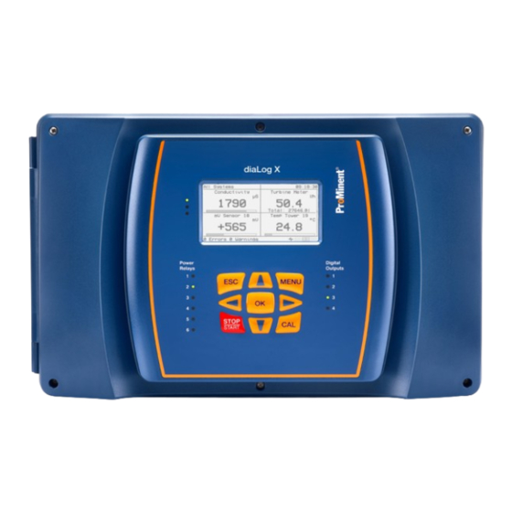
Operating concept of the device Operating concept of the device 2.1 Front panel The controller features a graphic LCD display to present real-time meas‐ ured values, statuses, and configuration information. Sensors can be cali‐ brated using the display and keyboard. The LEDs on the front display the status of relays, digital outputs, and alarms. -
Page 8: Functions Of The Keys
Operating concept of the device 2.2 Functions of the keys Tab. 2: Functions of the keys Function Confirmation in the setting menu: acknowledges and saves the input of values. Confirmation in the continuous display: displays all information about saved errors and warnings. Back to the continuous display or to the start of the respective setting menu in which you currently find yourself. -
Page 9: Navigation In The Controller's Menu Display
Navigation in the controller’s menu display Navigation in the controller’s menu display Most of the menu points are self-explanatory, but some menu points are explained in detail. It is not possible to create applications with the key‐ board. Log in to the device using a smartphone or computer if you wish to Ä... - Page 10 Navigation in the controller’s menu display All systems 11:54:11 Cooling tower pH 6.8 pH PID ORP 100% PID ORP 100.0 Chlorine 72.01 ppm Cooling tower ORP 0.5 mV Cooling tower conductivity 744µS Water meter 11 m3 Turbine meter 12.2 l/h Today 11.0 l 0 errors...
- Page 11 Temperature unit °C Unit metric Log interval Local User Timeout 900s Remote Prominent login C0120 Fig. 8: ‘Device setup’ menu ‘Device’ : ‘Device setup’ menu to enter and adapt basic settings, Use the e.g.: Time and date Settings for SI units...
- Page 12 Navigation in the controller’s menu display ‘Device’ menu: ‘Network Settings’ : ‘WiFi’ WiFi IP Address 169.168.001.001 diaLog_X_1644 Password 1234567890 QSSID C0122 Fig. 10: ‘WiFi’ menu ‘Device’ : ‘Network Settings’ : ‘WiFi’ menu to enter and adapt Wi- Use the Fi settings, e.g.: IP address in the Wi-Fi SSID: Name by which the device is displayed in the Wi-Fi Password for the Wi-Fi connection/SSID...
-
Page 13: Identity Code
Identity code Identity code diaLog X Regional code EU Europe Type of installation W Wall mounted Design 00 with ProMinent logo Function XX None Operating panel A Master unit B Satellite Supply voltage 4 24 V DC 6 100 ... 230 V, 50/60 Hz... - Page 14 Identity code AA mA/mA sensor input mV/mV temperature sensor input Extension slot 4 No module Serial sensor, module 2, control Conductivity/temperature sensor input mV/temperature and mA module mA/mA output mA/mA sensor input mV/mV temperature sensor input Pump activation (P/V) Relay without presetting Pre-wired outputs None (not for European versions) Inhibitor metering outputs...
-
Page 15: Safety And Responsibility
Safety and responsibility Safety and responsibility 5.1 Labelling of Warning Information Introduction These operating instructions provide information on the technical data and functions of the product. These operating instructions provide detailed warning information and are provided as clear step-by-step instructions. The warning information and notes are categorised according to the fol‐... -
Page 16: General Safety Information
Safety and responsibility 5.2 General safety information WARNING! Danger from hazardous substances! Possible consequence: Fatal or very serious injuries. Please ensure when handling hazardous substances that you have read the latest safety data sheets provided by the manufacture of the hazardous substance. The actions required are described in the safety data sheet. -
Page 17: Intended Use
Safety and responsibility 5.3 Intended use INFORMATION: Intended use The controller is designed to measure and control liquid media. The labelling of the measured variables is indi‐ cated in the controller display and is absolutely binding. The protection provided by the pump can be impaired if this controller is used in a manner not specified in the operating instructions. -
Page 18: User Qualification
Safety and responsibility 5.4 User qualification WARNING! Danger of injury with inadequately qualified personnel The operator of the system / equipment is responsible for ensuring that the qualifications are fulfilled. If inadequately qualified personnel work on the unit or loiter in the hazard zone of the unit, this could result in dangers that could cause serious injuries and material damage. -
Page 19: Network Security
The operator/user should replace all default passwords with appropriate and adequately secure passwords during commissioning. Responsibility for network security lies with the operator of the system. ProMinent GmbH in particular is not liable for any consequences resulting from inadequate security measures and the potential misuse of the user’s authentication... -
Page 20: Ambient Conditions: Storage And Transport
Ambient conditions: storage and transport Ambient conditions: storage and transport Ä Chapter 5.4 ‘User qualification’ User qualification: instructed user on page 18 Ambient conditions: storage and transport Permissible ambient temperature: - 20 ... 60 °C (- 4 ... 140 °F) Humidity: maximum 95% relative air humidity, non-condensing. -
Page 21: Assembly And Installation
Assembly and installation Assembly and installation User qualification, mechanical installation: trained and qualified per‐ Ä Chapter 5.4 ‘User qualification’ on page 18 sonnel User qualification, electrical installation: electrical technician Ä Chapter 5.4 ‘User qualification’ on page 18 The controller must be installed in such a way that the mains power plug can be easily disconnected or that the circuit breaker is easily accessible. - Page 22 Assembly and installation Wall mounting Take the wall bracket out of the housing A0490 Fig. 12: Removing the wall bracket Pull the two snap hooks (1) outwards ð The wall brackets snaps slightly downwards. Push the wall bracket downwards (2) from the housing and fold (3) it Use the wall bracket as a drilling template to mark the positions of four drill holes Drill the holes: Ø...
- Page 23 Assembly and installation A0491 Fig. 13: Fitting the wall bracket Screw the wall bracket into position using the washers, see Fig. 13 A0492 Fig. 14: Fitting the wall bracket Hook the bottom of the housing (1) into the wall bracket Lightly press the housing at the top (2) against the wall bracket Then check that the housing is hooked in at the top and press down (3) until it audibly engages...
-
Page 24: Electrical Installation
Assembly and installation 7.3 Electrical installation Safe operating status: Both hardware and software safety precautions must be taken to ensure that the controller adopts a safe operating status in the event of a fault. For instance, use limit switches, mechanical locks, ... During installation, ensure that the controller is not energised. -
Page 25: Connecting The Terminals
Assembly and installation 7.3.3 Connecting the terminals There is also a field containing connection information next to the termi‐ nals on the modules. Strip the sleeve from the end of the cable as shown in Fig. 15 and press on the corresponding cable end sleeves. To install the cables, push the screwdriver supplied right into the square opening of the respective terminal to insert the cable end into the terminal block. - Page 26 Assembly and installation Designation Terminal identifier Terminals Signal Function 4 (PE) Protective earth con‐ ductor Output relay 6 feeding 11 (L*) Phase switched switched 7 (N) Neutral con‐ ductor 3 (PE) Protective earth con‐ ductor Output relay 5 feeding Powered relays Rel 5 10 (L*) Phase Output relay 100 - 230...
- Page 27 Assembly and installation Designation Terminal identifier Terminals Signal Function Potential-free output Dry relays Rel 3 1 (COM) Root Potential-free output relay 3 relay 100 - 230 V AC 2 (NO) Normally or 24 V DC Open 3 (NC) Normally Closed Potential-free output Dry relays Rel 2 1 (COM)
- Page 28 Assembly and installation Designation Terminal identifier Terminals Signal Function 3 (+V) +15 V/10 mA power supply Digital input 4 1 (-) Reference External contact input potential with 15 V/10 mA power supply 2 (+) Contact input 3 (+V) +15 V/10 mA power supply Digital input 3 1 (-)
-
Page 29: Switching Of Inductive Loads
Customer LAN interface USB interface for customer’s USB memory stick Micro SD card ProMinent internal micro SD card reader 7.4 Switching of inductive loads If you connect an inductive load, i.e. a consumer which uses a coil (e.g. an alpha motorised pump), then you must protect your controller with a protective circuit. - Page 30 Assembly and installation Also when switching on, the resistor acts as a current limiter for the capac‐ itor charging process. The RC member protective circuit is highly suitable for AC voltage supplies. The magnitude of the resistance R of the RC member is determined according to the following equation: R=U/I (Where U= Voltage across the load and I...
-
Page 31: Information On Fieldbus Products
Information on fieldbus products Information on fieldbus products You will find further information on our fieldbus products, including GSD www.prominent.com/fieldbus files, operating instructions etc. at:... -
Page 32: Establishing A Network Connection
Establishing a network connection Establishing a network connection The controller can simultaneously communicate via Ethernet and Wi-Fi. Network connections can be used for: Programming, Configuration, Calibration, Graphic display, Downloading data, Monitoring the program control status, Alarms, Installation of a new program, Saving the current program, Updating the software. -
Page 33: Wi-Fi With A Smartphone
Establishing a network connection 9.1.2 Wi-Fi with a smartphone Navigate to the 'Settings' page of your smartphone. Select the Wi-Fi page. ð A list of all available Wi-Fi networks appears. Select [dialogX_123] . The number 123 in this example is different with each controller. These 3 digits are taken from the last 3 digits of the serial number of the controller. -
Page 34: Determine The Lan Ip Address Of The Controller
Establishing a network connection Use the special green Ethernet cable provided to connect to the LAN connector on your end device and the LAN connector on the cover of the controller. It is located at the bottom left corner of the controller marked “LAN”. -
Page 35: General Layout And Terminal Diagrams
General layout and terminal diagrams General layout and terminal diagrams The figures in this section show the general position of the electronic com‐ ponents and the cable connections. Cover layout A3563 Fig. 18: Cover layout Base layout A3564 Fig. 19: Base layout... -
Page 36: Digital Input And Digital Output Relay Status Displays
General layout and terminal diagrams Power supply A3565 Fig. 20: Controller power supply without safety cover 10.1 Digital input and digital output relay status displays Fig. 21: Text display to present I/O values and information. - Page 37 General layout and terminal diagrams A3566 Fig. 22: Digital inputs with active status LEDs A3567 Fig. 23: Digital outputs with active status LEDs...
- Page 38 General layout and terminal diagrams A3568 Fig. 24: Output relays with active status LEDs. Relay displays. The LEDs light up when the relay is activated. Physical relays Relay terminals The fuses, relays and relay displays are located under the safety cover of the power supply.
-
Page 39: Inputs And Outputs
Inputs and outputs Inputs and outputs 11.1 Overview Inputs and outputs are each sub-divided into 4 categories: Analogue inputs, Analogue outputs, Digital inputs, Digital outputs. The digital signals are further sub-divided into: On/Off, Low frequency High frequency Discrete signals (directly wired to the controller) are described first, fol‐ lowed by signals supplied by a network cable, such as CAN Bus or MODBUS. -
Page 40: Analogue Inputs
Inputs and outputs A3569 Fig. 25: 4 expansion modules in their module slots. Analogue signals are connected to the expansion modules. The direct connection of analogue sensors requires 1 module, as shown here. Sen‐ sors connected via a network cable are described in section 12. There are 6 types of module card and 4 module slots (Slot 1 ... -
Page 41: Module With 2 Serial Inputs (Ctfs-Lpr)
Fig. 26: This view of the extension module shows details of the slots. 11.2.1 Module with 2 serial inputs (CTFs-LPR) Only certified serial ProMinent sensors, CTFS (Conductivity Temperature Flowswitch Serial) and Log R serial corrosion rate may be used with these inputs. -
Page 42: Two-Channel Conductivity/Temperature Input Module
Inputs and outputs 11.2.1.1 Module: 2x serial sensors. Part number 1092566 Belegungsvarianten Serieller Sensor A2386 Fig. 27: Module: 2x serial sensors. Part number 1092566 A module for connecting digital sensors of type CTFS and digital corrosion sensors. Maximum cable length: 30 m, limited by the EMC specification. 11.2.2 Two-channel conductivity/temperature input module The two-channel conductivity/temperature input module can be pro‐... - Page 43 The Pt sensors are RTDs. The pH/ORP module does not accept LM335 temperature sensors and the ‘H’ input does not accept Pt1000 sensors. ProMinent supplies the fol‐ lowing temperature sensors: Pt1000 RTD with part number 1080101, which is only available as part of the set with part number 1082254.
- Page 44 Inputs and outputs Electrical data Parameter Value Cell constant: 0.005 1/cm ... 15 1/cm Measuring ranges dependent on the sensor type: Specific conductivity: 0.001 µS/cm ... 200 mS/cm Specific electrical resistance: 5 Ωcm ... 1000 MΩcm TOS (total dissolved solids): 0 ...
- Page 45 Inputs and outputs Accessories Part number Measuring line LF 5 m: 1046026 Measuring line LF 10 m: 1046027 Selection of the connected sensor All of the sensor-dependent settings are reset to the [DEFAULT] values when changing the connected sensor. Sensor Connector Cell constant T-correction...
-
Page 46: Dual Ph/Orp-Temperature Input Module
Inputs and outputs 11.2.2.4 Typical connection versions A3570 Fig. 29: A3570 I: The 2-wire conductivity sensor for boilers is connected to pins XE1 or XE4 and 1 is not sensitive to polarity. II: 4-wire condensate-conductivity/temperature sensor is connected, as shown, to XE1 and XE2 or XE3 and XE4. The conductivity wires, red and black, to XE1 and XE4 and are not polarity-dependent. - Page 47 11.2.3.2 Attaching the pH/ORP coaxial cable If possible, use only complete coaxial cables, which you can select from the ProMinent catalogue. Ä Tab. 4 ‘Sensor connection cable, coaxial, for ter‐ Part numbers: minal XE1/XE2 and X5/X6’ on page 47 .
- Page 48 Inputs and outputs A3571 Fig. 31: pH/ORP module coaxial connector / positioning of the coaxial cable XE1 shield terminal complete with top part XE2 connector terminals for the coaxial inner conductor XE6 connector terminals for the coaxial inner conductor XE5 shield terminal holder After preparing the cable, connect it to the pH/ORP module.
-
Page 49: Module With 2X Ma Inputs
Inputs and outputs A0947 Fig. 33: Coaxial cable construction 11.2.4 Module with 2x mA inputs The two-channel 4 ... 20 mA input module can process active and passive control loops. Both inputs are isolated from each other and from the lower printed circuit board. -
Page 50: Ph/Orp, Temperature And Ma Input Module
(PES), and pH and ORP via the pH transmitters, pHV1, part number 809126, and ORP, RHV1, part number 809127. For use with ProMinent 2-wire transmitters and sensors with 2-wire mA interface. Processing of active mA signals (type of connector: current source). - Page 51 2-wire sensor, e.g. for chlorine, bromine or peracetic acid (PES). mA interface: For use with ProMinent 2-wire transmitters and sensors with 2-wire mA interface. Processing of active mA signals, type of connector: current source.
-
Page 52: Connection Of An Amperometric Sensor
Fig. 36 and Fig. 37. We will also show you how to wire the inputs that are externally supplied, Fig. 38. ProMinent amperometric sensors can be connected to a 4 ... 20 mA input Ä Chapter 11.2.4 module. -
Page 53: Little Dipper ® Ii Ma Connector
Inputs and outputs A3573 Fig. 38: We will also show you how to wire the inputs that are fed externally. 11.2.7 LITTLE DIPPER II mA connector ® The Turner ® Designs Little Dipper II inline fluorometer can be connected to a dual mA input module. The sensor needs 8... 30 VDC. Brown Supply to the sensor 8 ... -
Page 54: Pyxis ® Installation
Inputs and outputs 11.2.8 Pyxis installation ® The Pyxis ® inline fluorometer can be connected to a dual mA input module or to the MODBUS master connector. The 4 ... 20 mA input can be wired in one of the two ways shown in the illustrations. The red and black wires supply the Pyxis inline fluorometer with 24 V DC. -
Page 55: Liquid Level Sensor With Ma Connector
Inputs and outputs 11.2.9 Liquid level sensor with mA connector A3588 Fig. 42: Liquid level sensor connected to a two-channel 4 ... 20 mA input module Tank A Tank B Two-channel 4 ... 20 mA input with isolated voltage supply. The two-channel mA input module can receive 2 suitable liquid level sen‐... -
Page 56: Module: 2X Ma Outputs. Part Number 1092565
Inputs and outputs 11.3.2 Module: 2x mA outputs. Part number 1092565 Assignment options 2x mA outputs A2414 Fig. 44: Module: 2x mA outputs. Part number 1092565 A module for recording measured values, for example via a measured value recorder, control of actuators, such as a motorised ball valve. Maximum load: 450 Ω... -
Page 57: Digital Outputs
Check this in the manual for the water meter. Water meters are available from your ProMinent agent. For a list of gauges, see the “Spare Parts” section of this manual. -
Page 58: Use Of A Prominent Universal Control Wire On A Pulse Output Relay
Inputs and outputs 11.5.2 Use of a ProMinent universal control wire on a pulse output relay A ProMinent pump using the universal control wire terminates with the brown, black and white wires, as shown here. The black line is general. The white line is the pulse signal. The brown line is for pause/activation. - Page 59 Inputs and outputs to the controller does not exceed 5 amps for a single relay. As relays 1 - 3 are “dry” contact relays, these relays can be used to supply motor pumps with higher amperages of up to 5 amps. Devices with higher amperage must be fed and protected from an external source.
-
Page 60: Connecting The Power Supply Or A Mains Cable
Inputs and outputs 11.6.2 Connecting the power supply or a mains cable No mains cable is supplied. Always use a suitable all-pole isolating device when connecting the con‐ troller to the supply voltage. A3597 Fig. 51: Mains cable 11.6.3 Wiring relays 4, 5 and 6 The following wiring diagrams show typical configurations, but not all pos‐... -
Page 61: Wiring Relays 1, 2 And 3 Using An External Power Source
Inputs and outputs 11.6.6 Wiring relays 1, 2 and 3 using an external power source The de-energised (dry) relays 1, 2 and 3 are not fused, so that any external connection to these relay terminals requires additional protection of the power circuit during installation. The figure Fig. -
Page 62: Commissioning
Commissioning Commissioning Ä Chapter 5.4 ‘User User qualification: trained qualified personnel qualification’ on page 18 Switch the controller on once mechanical and electrical installation has been completed. 12.1 Switch-on behaviour during commissioning Switching on – First steps The process takes a few seconds, depending on the size of your configu‐ ration. -
Page 63: Operation Via A Browser
Operation via a browser Operation via a browser Ä Chapter 5.4 ‘User qualification’ User qualification: trained user on page 18 The browser connection consists of 2 windows: the Hardware window, on which the inputs and outputs (I/O) are configured, and the Application window (Apps), on which the processes are monitored and controlled by program applications. -
Page 64: Application (Apps) Window, Basics
Operation via a browser 13.2 Application (Apps) window, basics A3636 Fig. 58: Application (Apps) window In the upper part of the browser view, you can switch back and forth between the views for applications (Apps) (1.) and Hardware (2.). The functionalities will be explained later. -
Page 65: Diagnostics
Operation via a browser All named operating fields are labelled in a clear and by self-explanatory way and can be opened and operated by tapping on them. 13.3.1 Diagnostics There are 6 Diagnostics sections. Status Web browser sessions Local HMI cards I/O cards Network properties Decentralised HMI... -
Page 66: Menu: Setup
Operation via a browser 13.3.1.4 I/O cards These Diagnostics pages are mainly used by the manufacturer of the con‐ troller. You can find information on the serial number, firmware etc. on these pages. 13.3.1.5 Network properties [Network properties] Diagnostics page provides helpful information on setting up the local area network (LAN). - Page 67 Operation via a browser 13.3.2.1 Set up device The administrator can set the time and date, or synchronise the controller with your PC or mobile phone on the “Set up device” page. You can change the date format, the temperature unit, the measuring system, and specify the data recording length.
- Page 68 Operation via a browser The boiler refill is located in “Boiler” and “Water consumption”. The “Water consumption” system has 2 applications. Change the system to Tower 1. All grey check boxes show only Tower 1 affiliation. The blue check boxes indicate affiliation of “Tower 1 system” and “Water consumption”.
-
Page 69: Menu: New Container
Operation via a browser 13.3.2.6 E-mail recipients Enter the e-mail addresses of all people who need to receive e-mails from this controller. 13.3.2.7 E-mail services There are 3 types of e-mails that the controller can deliver. You can select 1, 2 or all types. Define the e-mail action and press Apply. 13.3.2.8 Email server configuration (SMTP) The e-mail service requires an SMTP server. - Page 70 Operation via a browser Controller settings Downloads Controller configuration files Live data logs Activity logs Alarm logs A3645 Fig. 65: Download 13.3.4.1 Controller configuration files 13.3.4.2 Live data logs You can download this CSV file to the default download folder of your browser by clicking on the respective CSV file.
-
Page 71: The Display Fields Of The Apps
Operation via a browser 13.4 The display fields of the apps The display fields of the applications display the current status in various ways. At the lower edge of most windows on the application screen are tiny up and down arrows (1) that let you select a different window size. Some have 3 sizes. -
Page 72: Setting Up The I/Os, The Hardware Page
14.2 Analogue I/Os Analogue sensor inputs and outputs require the use of different types of module. ProMinent amperometric sensors, such as chlorine and peracetic acid, as well as the conductivity, Pyxis and Little-Dipper sensors require an mA ®... -
Page 73: Hardware Fields
Setting up the I/Os, the Hardware page Establish a connection to the controller via a PC or other suitable device. A3636 Fig. 68: Application (Apps) window Click on the [Hardware] (2) symbol to switch to the [Hardware] page. A3640 Fig. 69: [Hardware] page [Hardware] page is to find and define the inputs The main purpose of the and outputs for use in applications. -
Page 74: Setting Up The Analogue Input Module
Setting up the I/Os, the Hardware page The terminal corresponds to the connector designation stated on the module. [true] , when the module is in operation. Online = Hardware type = The module type. Process value = This value represents the calibrated variable. Raw value = From the input module without calibration adjustment. -
Page 75: Dual Mv Input Module
Setting up the I/Os, the Hardware page [General] tab are automatically populated if you select a The fields on the fluorescence mA input on the [Configure] tab. You can edit these preset‐ tings if you need to. There is a fluorescence selection for the Little Dipper ®... -
Page 76: Ph/Orp Temperature And Ma Input Module
The list of possible mA inputs is the same as for the dual mA input module, which includes every ProMinent amperometric sensor. The pH sensor can be used to compensate for a free chlorine sensor. If required, the mA input can then be used for most 4 ... - Page 77 Setting up the I/Os, the Hardware page [true] , when the module is working Online = Hardware type = mA input. Process value = Scaled raw value, including all calibration changes. Raw value = From the input module without calibration adjustment. Calibration = Shows the current values for gain and offset.
-
Page 78: Module With 2 Serial Inputs
14.3.4 Module with 2 serial inputs The serial input module is compatible with the ProMinent CTFS sensor and serial corrosion sensors. Both sensors are three-wire sensors. The information from the sensors is transmitted to the controller as serial data. - Page 79 Setting up the I/Os, the Hardware page The PCB position (Printed Circuit Board) refers to the slots of the module and the terminal is labelled the same as the input on the module. [true] , when the module is working Online = Hardware type = Conductive conductivity.
- Page 80 Setting up the I/Os, the Hardware page [true] , when the module is working Online = Hardware type = Digital input of a serial CTF sensor [Polarity] tab. Process value = Status of the switch after editing the Raw value = CTF sensor value Flow meter = An analogue presentation of the switch status...
-
Page 81: Setting Up The Analogue Output Module
Setting up the I/Os, the Hardware page 14.3.4.3 Dual conductivity/temperature module The dual conductivity/temperature module has 4 fields. This module is compatible with a variety of conductivity/temperature sensors, but not with the serial CTFS. [Conductivity] menu symbol to open the [Diagnostics] and Conductivity Use the [General] tabs. -
Page 82: Setting Up The Digital Input
Setting up the I/Os, the Hardware page 14.5 Setting up the digital input The digital inputs do not accept a voltage signal. The input terminal sup‐ plies 14 V DC on the (+) line and monitors the (-) terminal for this signal. That way, the controller sees a potential-free contact. -
Page 83: Setting Up The Digital Output
Setting up the I/Os, the Hardware page The raw value is the current status of the input, active (closed) or inactive (open). Used by apps, if applicable. You can select a digital type on the “Configure” tab. 3 types can be selected for the digital inputs. “Contact”... -
Page 84: Digital Low-Voltage Outputs
Setting up the I/Os, the Hardware page Digital outputs (XA1 - XA4) Digital output XA3 Digital output XA4 Digital output XA1 Digital output XA2 Digital output XA2 Digital output XA1 Digital output XA3 Digital output XA4 Potential-free relays (XR1 - XR3) Relay XR3 Rel3 Relay XR1 Rel1 Non Ox A... - Page 85 Setting up the I/Os, the Hardware page You can name the output, and adjust the unit of measure and the decimal places on the [General] tab. The unit of measure helps to manage the accuracy of the display output rate. The decimal places only influence the value displayed on the Hardware page.
-
Page 86: Configuring The Applications
Configuring the applications Configuring the applications Ä Chapter 5.4 ‘User qualification’ User qualification: trained user on page 18 15.1 Introduction When the inputs and outputs are configured, you can create the applica‐ tions to monitor sensors, counter inputs and signal outputs. You can use these inputs to control the digital, powered and analogue outputs. -
Page 87: Creating Applications
Configuring the applications To create a new container, click the menu symbol (often referred to as the hamburger menu) on the Home screen and select “New con‐ tainer” from the drop-down menu. Give the container a name. Preferably a name that indicates its future contents. -
Page 88: Water Meter Measuring Application
Configuring the applications Select a container for your application. Click on the gear symbol in the container menu. [ Create new application] , [Measuring applications] Then select the [Sensor] options in the drop-down box. and then [Create sensor] . Press Then select the system affiliation(s) on the General tab. -
Page 89: Application For Measurement With Turbine Meters
Configuring the applications 15.4.3 Application for measurement with turbine meters Select a container for your application, Click on the container menu gear symbol, [Create new application] , [Measuring application] and Then select [Turbine meter] in the drop-down box. then [Create turbine meter] . Click on [General] tab, select the system affiliation, edit the Then, on the... -
Page 90: Application For Manual Inputs
Configuring the applications The “Clear/Remove” page is the same for all applications. The page con‐ tains an explanation of the process. 15.4.5 Application for manual inputs Expected use: The results of the intermittent water tests are timestamped and can be graphically displayed with other chemical and biological events. -
Page 91: Boolean Operators
Configuring the applications 15.5.2 Boolean operators Boolean logic: Two values linked with AND must both be true for the output to be true. Therefore, A and B will only result in an active output if both A and B are true. The logic of the OR link is such that the output is true if one of the inputs, A or B, is true. -
Page 92: Application: Status Change
Configuring the applications [General] tab to select a system affiliation and name the Use the process. The system affiliation lets you group your applications. The browser view can be manipulated by switching the affiliation symbols. The Input formula page provides up to 6 input variables that can be used in the formula. -
Page 93: Application: Timed Event
Configuring the applications [Create new application] , [Time controlled] , and then Then select [Percentage-based time] in the drop-down box. [Create percentage-based time] . Click on [General] tab to edit a system affiliation and name the appli‐ Use the cation. The system affiliation enables you to group your applications. -
Page 94: Application: Timed Volume Event
Configuring the applications The “Clear/Remove” page is the same for all applications. The page con‐ tains an explanation of the process. 15.6.3 Application: Timed volume event This works in a similar way to the Timed event application, except that the application will end after dispensing a certain volume, and not after a cer‐... -
Page 95: Measured Value Control Applications
Configuring the applications 15.7 Measured value control applications The measuring control applications activate digital outputs and relay out‐ puts based on sensors created as measuring applications. These applica‐ tions can control multiple outputs, including digital relays and analogue 4 ... 20 mA outputs. 15.7.1 Application: Sensor-based bleeding The Sensor-based blowdown application is designed to control the con‐... -
Page 96: Application: On/Off
Configuring the applications Refer to the “Blocked by” heading. This heading is to remind you that the output you have just created is partly controlled by the out‐ puts selected here. The “Clear/Remove” page is the same for all applications. The page con‐ tains an explanation of the “Clear/Remove”... - Page 97 3): After the “Pause” signal has been activated via the pump cable. ProMinent pumps have control cable options that include a pause function, the brown cable. You can find more information in the [PID Tuning] tab to enter a setpoint and the pump manual.
-
Page 98: Application: Feed Meter
Configuring the applications XP is the proportionality factor. The proportionality factor indicates that the output varies proportionally to the setpoint over the XP range. For instance, the ORP setpoint is 400 mV and the XP value is 20 mV. 20 mV is the operating range for the output. This sets the controller so that the controller outputs 0 speed when the process value reaches the setpoint, and outputs 100% when the process value XP (20 mV) is below the setpoint. -
Page 99: Application: Two-Way
Configuring the applications [Blocking applications] tab displays all other outputs that can be used to disconnect this output when the outputs are on (block, if active) or off (block, if inactive). The activation delay keeps this output off for a few additional sec‐ onds or minutes if necessary. -
Page 100: Application: Timed Cycles
Configuring the applications 15.7.6 Application: Timed cycles [Timed cycles] application is a simple but effective method for aver‐ [Timed cycles] prevents overshooting in aging the chemical feed. metering. A sensor-controlled pump may not be able to control the process because there is a delay between the supply of the chemical and the sensor changing. -
Page 101: Special Control Applications
Configuring the applications [Limit values] tab to set up warnings and alarms. The oper‐ Use the ating limit may indicate an output stuck in the On status or an error in the settings. The daily limit value could be due to a leak in the cooling system. In summer temperatures, it may be necessary to increase this value, while a lower value may be required in winter temperatures. -
Page 102: Application: First Blowdown, Then Feed
Configuring the applications [Blocked by] heading. This is to remind you that the output Note the you have just created is partly controlled by the outputs selected here. There are no alarm limit settings for this application. Note that the event window displays your current weekly even/odd status. -
Page 103: Blowdown And Feed
Configuring the applications [Limit values] menu to set alarms and warnings for each Use the activation and/or each day. If the pump relay does not use the blocking function and you set a time period of 10 minutes and the pump’s on time is 50%, then the pump should never run for more than 5 minutes per activation. -
Page 104: Sampling
Configuring the applications The daily limit helps you to detect overfilling. [Assigned output] tab. All the available out‐ Select an output on the puts are displayed. [Blocking applications] tab displays all other outputs that can be used to disconnect this output when the outputs are on (block, if active) or off (block, if inactive). - Page 105 Configuring the applications III. VIII. VII. A3634 Fig. 75: Boiler with sampling pipework Boiler, maximum 17 bar (250 PSI) Bleed valve Surface of the bleed pipework VII. Needle throttle valve III. Shut-off valve VIII. Shut-off valve Bypass valve Free flow to the drain Conductivity sensor The 2-wire conductivity sensor used in the sampling method is not ther‐...
-
Page 106: Scaling The Output
Configuring the applications At the end of the measuring time, a snapshot of the sensor value is recorded and compared with the setpoint. If the measured value is above the setpoint, the routine moves to the next sample and reopens the valve for the sampling time, as it did at the beginning. After the sampling time, the valve closes as before and allows the sample to cool down during the measuring time. -
Page 107: Calibrating The Controller
Calibrating the controller Calibrating the controller Fig. 76: The continuous display with the CAL key Calibrate Use the CAL key or the Setup menu to calibrate sensors and 4 ... 20 mA input signals. You can only calibrate measuring applications. To select an application, press OK, and then use the up and down arrow keys to search for the required application. - Page 108 Calibrating the controller For example, if you have selected the calibration process, use the Up and Down arrows to scroll through the selection options. Press OK to select and return to the previous page. Review all selections to familiarise yourself with the program. Press CAL to start.
-
Page 109: Maintenance Of The Sensors
Maintenance of the sensors Maintenance of the sensors 17.1 Cleaning the sensors Clean all sensors, as described in the operating instructions for the sen‐ sors. 17.2 Calibrating the sensors Calibrate all sensors, as described in the operating instructions for the Ä... -
Page 110: Charts And Data To Download
Charts and data to download Charts and data to download A3635 Fig. 77: [Charts] tab [Charts] tab in the browser screen to record up to 4 I/Os simulta‐ Use the neously. -
Page 111: Technical Data
Technical data Technical data 19.1 Fuse specification Tab. 6: Fuse specification Component Rating/Type Supplier Part# Mains power input 2.5 amps at 250 V AC, 5x20 mm 732413 Output fuse for XP1: 10 amps at 250 V AC, 5x20 mm 733855 Maximum load: 8 A (due to ambient temperature) Relay fuses R4, R5 and R6 10 amps at 250 V AC, 5x20 mm. -
Page 112: Can Bus (Xc1
Technical data 19.4 CAN Bus (XC1 ... XC3) Local CAN bus with external power supply 20 V DC/400 mA The shield has no connection to the earth potential 19.5 Modbus slave Standard RS-485 module. The 120 Ohm termination can be activated by the software. Tab. -
Page 113: Controller Specification
Technical data 19.8 Controller specification Tab. 11: Controller specification Description Technical data Control characteristic: ON/OFF, P, PID, pulse frequency control Control: 10 relays (see below) Signal current output: 4 ... 20 mA galvanically isolated, max. load 450 Ω, range and assignment (measured, correction, control variable) can be switched. - Page 114 Technical data Description Technical data Connector type mV: Potentiometric measured variables, measuring ranges corresponding to the transmitters Conductivity (variable Ohm): 0 ... 5,000 μS Conductivity (measuring ranges depending on 0 ... 5,000 μS with a digital signal transmitter): Temperature: Via Pt 100/Pt 1000, measuring range 0 ... 150 °C pH resolution: 0.01 Resolution of the ORP voltage:...
-
Page 115: Maintenance
Maintenance Maintenance Maintenance Solvents Never under any circumstances use solvent to clean the surfaces. Solvents can attack the surfaces. Clean the enclosure with a damp cloth. Then rub dry. The controller is maintenance-free. Replace the batteries after 10 years as a precautionary measure. -
Page 116: Warnings, Alarms, And Errors
Warnings, alarms, and errors Warnings, alarms, and errors Active alarms Controller alarms App alarms Alarm App alarms Type Code Application Description Alarm Conductivity Hardware missing Alarm Drain Input application Alarm Temperature Hardware missing Alarm Drain-then-refill Input application A3646 Fig. 79: Warnings, alarms, and errors The controller has a notification process that signals control alarms, process alarms and warnings as well as user selection errors to users. - Page 117 Warnings, alarms, and errors Errors occur when the operator has made a mistake or made an incorrect selection. The notes in the pop-up window are self-explanatory. Alarms can be acknowledged by any user. Internal controller alarms Real-time clock battery low. Internal SD card error.
-
Page 118: Disposal Of Used Parts
Decontaminate the device before returning it. To do so, remove all traces of hazardous substances. Refer to the material safety data sheet for your feed chemical as well. A current Declaration of Decontamination is available to download on the ProMinent website. -
Page 119: Standards Complied With And Declaration Of Conformity
Standards complied with and Declaration of Conformity Standards complied with and Declaration of Conformity ProMinent GmbH Im Schuhmachergewann 5 - 11 D - 69123 Heidelberg, Germany, hereby declare that the product specified below complies with the relevant basic health and safety requirements of the EU Directives, on the basis of its functional concept and design and in the version distributed by us. -
Page 120: Index
Index Index Action, step by step ......2 Recycling ....... 20 Ambient temperature, permitted . - Page 124 ProMinent GmbH Im Schuhmachergewann 5 - 11 69123 Heidelberg, Germany Telephone: +49 6221 842-0 Fax: +49 6221 842-419 Email: info@prominent.com Internet: www.prominent.com 990203, 2, en_GB © 2024...
Need help?
Do you have a question about the DULCOMETER diaLog X and is the answer not in the manual?
Questions and answers