Table of Contents
Advertisement
Quick Links
Advertisement
Table of Contents
Troubleshooting

Related Manuals for Alpha Group OutBack Power MATE3


Summary of Contents for Alpha Group OutBack Power MATE3
- Page 1 MATE3 System Display and Controller Owner’s Manual...
- Page 2 About OutBack Power Technologies OutBack Power Technologies is a leader in advanced energy conversion technology. Our products include true sine wave inverter/chargers, maximum power point tracking charge controllers, and system communication components, as well as circuit breakers, accessories, and assembled systems. Contact Information Telephone: +1.360.435.6030 (North America)
-
Page 3: Important Safety Instructions
Important Safety Instructions READ AND SAVE THESE INSTRUCTIONS! This manual contains important safety instructions for the MATE3 System Display and Control. Read all instructions and cautionary markings on the MATE3 and on any accessories or additional equipment included in the installation. Failure to adhere to these instructions could result in severe shock or possible electrocution. - Page 4 Important Safety Instructions Table 1 Terms and Definitions Term Definition Direct Current; refers to voltage produced by the batteries or renewable source Electrical Testing Laboratories; short for the company ETL Semko; refers to a certification issued by ETL to OutBack products indicating that they meet certain UL standards Federal Communications Commission FNDC FLEXnet DC Monitor;...
-
Page 5: General Safety
Important Safety Instructions General Safety WARNING: Limitations on Use This equipment is NOT intended for use with life support equipment or other medical equipment or devices. CAUTION: Equipment Damage Only use components or accessories recommended or sold by OutBack Power Technologies or its authorized agents. -
Page 6: Fcc Information To The User
Important Safety Instructions FCC Information to the User This equipment has been tested and found to comply with the limits for a Class B digital device, pursuant to part 15 of the FCC Rules. These limits are designed to provide reasonable protection against harmful interference in a residential installation. -
Page 7: Recycling Information
Important Safety Instructions Recycling Information IMPORTANT: Recycle Electronics and Batteries Batteries are considered hazardous waste and must be recycled according to local jurisdiction. Inverters and other electronics contain metals and plastics that can (and should) be recycled. The following are some websites and phone numbers that provide information and “how”... -
Page 8: Natural Resources Canada
Important Safety Instructions Natural Resources Canada Address: 580 Booth, Ottawa, ON K1A 0E8 Phone: +1.613.995.0947 TTY: +1.613.996.4397 (Phone and TTY: Monday to Friday, 8:30 a.m. to 4:30 p.m. ET) Web site: http://www.nrcan-rncan.gc.ca/mms-smm/busi-indu/rec-rec-eng.htm Office of Waste Management, Canada Address: Office of Waste Management Conservation and Protection Environment Canada Ottawa, Ontaro K1A 0H3... -
Page 9: Table Of Contents
Table of Contents Important Safety Instructions ................1 Symbols Used ....................................1 Audience ......................................1 Definitions.......................................1 General Safety ....................................3 Personal Safety....................................3 FCC Information to the User..............................4 Regulatory References................................4 Recycling Information ................................5 Earth 911, USA......................................5 Environmental Protection Agency, USA............................5 Keep America Beautiful, USA ................................5 OurEarth.org, USA.....................................5 National Institute of Recyclers, Mexico..............................5 Natural Resources Canada ..................................6... - Page 10 Table of Contents Meter Bars .........................................25 Off Grid Home Screen ...................................26 Grid Tied Home Screen..................................27 Basic Navigation ..................................28 Soft Keys ........................................28 Battery Soft Key ..........................................29 Inverter Soft Key...........................................37 Charge Controller Soft Key.......................................43 Grid Soft Key ..........................................46 Hot Keys........................................47 INVERTER Hot Key........................................47 CHARGER Hot Key........................................48 GEN Hot Key...........................................52 EVENTS Hot Key..........................................53...
- Page 11 Table of Contents Shunt Enable..........................................108 Relay Mode..........................................109 Relay Set Points..........................................110 Reset to Factory Defaults .......................................111 MATE Settings .......................................112 Advanced Generator Start (AGS) Mode ................................114 Data Logging ..........................................126 High Battery Transfer (HBX)....................................127 Grid Use Time ..........................................129 Charge Controller Float Coordination................................131 FLEXnet DC Advanced Control ....................................132 Reset to Factory Defaults Screens..................................133 Configuration Wizard................................134 Data Logs....................................134...
- Page 12 Table of Contents List of Tables Table 1 Terms and Definitions................................1 Table 2 HBX Mode Default Set Points............................127 Table 3 Basic Troubleshooting................................. 137 Table 4 Menu Map (System Settings) ............................143 Table 5 Menu Map (Inverter Settings) ............................144 Table 6 Menu Map (Charge Controller Settings)........................
- Page 13 Table of Contents Figure 37 Grid Soft Key Screens................................46 Figure 38 Sell Status Screen..................................46 Figure 39 Navigating with the Hot Keys.............................. 47 Figure 40 Using the INVERTER Hot Key..............................47 Figure 41 CHARGER Hot Key..................................48 Figure 42 Using the CHARGER Hot Key (Bulk Charge) ........................
- Page 14 Table of Contents Figure 92 MPPT......................................96 Figure 93 Temperature Compensation ..............................97 Figure 94 Battery Equalize ..................................98 Figure 95 Grid Tie Mode ....................................99 Figure 96 Auxiliary Output ..................................100 Figure 97 Vent Fan....................................101 Figure 98 PV Trigger....................................101 Figure 99 Error Output ....................................
-
Page 15: Introduction
Introduction Purpose A renewable energy system requires some combination of inverter/chargers, batteries, charge controllers, a renewable energy power source, as well as often interfacing with a generator. All of these components need to be adjusted and monitored for optimum performance. Functions The MATE3 System Display and Control provides a window to the system and allows for programming of each OutBack component for maximum efficiency. -
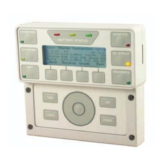
Page 16: Figure 1 Mate3 Features
Introduction LCD Screen Battery Status LEDs (x3) EVENTS Hot Key INVERTER Hot Key Event LED (Red) Inverter Status LED (Yellow) SD Memory Card CHARGER Hot Key AC INPUT Hot Key Charger Status LED (Green) AC Status LED (Yellow) FAVORITE Hot Key GEN(erator) Hot Key Favorite Status LED (Green) GEN Status LED (Green) -
Page 17: Installation
Installation Location Considerations The following information is important to consider when installing the OutBack MATE3. The MATE3 is intended for indoor installations only. Installing the MATE3 outdoors could expose it to damaging environmental conditions. Such damage is not covered by the limited warranty. ... -
Page 18: Dimensions
Installation Dimensions SD Card Slot Front Cover Mounting Holes (x4) Figure 2 MATE3 Dimensions To Install the MATE3 1. Install all other OutBack components first. 2. Locate the position for the MATE3. Allow room (approximately 2-3”) on the right side of the MATE for the SD Card to be inserted or removed. -
Page 19: Figure 3 Mate3 Connections (No Hub)
Installation NOTE: The MATE3 can also be connected directly to a charge controller. It cannot be connected directly to a FLEXnet DC monitor without a HUB and other OutBack devices such as an inverter or charge controller. Figure 3 MATE3 Connections (no HUB) 900-0117-01-00 Rev A... -
Page 20: Figure 4 Mate3 Connections (With Hub)
Installation This feature is not implemented at this time. Figure 4 MATE3 Connections (with HUB) 900-0117-01-00 Rev A... -
Page 21: Set Points
Installation Set Points A set point is a condition, measurement, or baseline that a user establishes in order for something else to happen (such as when to start or stop a generator). For example: Example #1. With a home thermostat, when predetermined temperatures and times are set for weekdays and weekends, the thermostat signals to a heating/cooling system to turn on at one time until a certain temperature is reached, maintain that temperature, and finally shut off at a later time, usually during sleep hours to conserve energy. - Page 22 Installation THIS PAGE INTENTIONALLY LEFT BLANK 900-0117-01-00 Rev A...
-
Page 23: Operation
Operation The MATE3 provides the means for programming OutBack inverter/chargers, charge controllers, and battery monitors when pre-programmed default settings do not work for the destined installation. IMPORTANT: The OutBack inverters have nonvolatile memory and will retain any settings that have been changed, even after the MATE3 is removed. If a system does not have a MATE3, an installer can bring a MATE3 to the site temporarily, install it, change the settings, and then remove it. -
Page 24: Led Status Indicators
Operation LED Status Indicators Battery LEDs Three LEDs provide a visual reference to indicate the condition of the battery bank. A GREEN LED means the batteries have an adequate charge at that time. It does not always mean they are full. -
Page 25: Gen Led (Green)
Operation Gen LED (green) This LED is located on the GEN hot key. (See page 52) It provides a visual reference for the status of a generator that is under control of the Advanced Generator Start (AGS) function. (See page 114.) ... -
Page 26: Favorite Led (Green)
Operation Favorite LED (green) This LED is located on the Favorite hot key. (See page 55.) It indicates the use of this hot key to select often-used menus for rapid access. ON (Solid): The hot key has been pressed and a Favorite can be selected. ... -
Page 27: Home Screen
Operation Home Screen The Home screen appears after the MATE3 detects the HUB (and any devices connected to it) or detects a single device if a HUB is not in use. Figure 7 Home Screen Symbols (example) Home Screen Types The Home Screen will vary depending on the “Type”... -
Page 28: Off Grid Home Screen
Operation Off Grid Home Screen LEGEND Icon(s) Description Icon(s) Description Battery Inverter Generator PV current charging Gen current used by inverter batteries and loads Battery current used by Net current flowing out of () or inverter () or charged by or into () batteries inverter () -
Page 29: Grid Tied Home Screen
Operation Grid Tied Home Screen LEGEND Icon(s) Icon(s) Icon(s) Icon(s) Battery Inverter Utility Grid Grid current used by inverter PV current charging and loads (), or inverter batteries current sold back to grid () Battery current used by Net current flowing out of () ... -
Page 30: Basic Navigation
Operation Basic Navigation Soft Keys Four soft keys are available to select the options displayed directly above each key. From the Home screen, up to four soft key options may be available. The left-center key, or Battery soft key, displays information on the battery bank and is marked with the symbol . -
Page 31: Battery Soft Key
Operation Generator Source Figure 11 Soft Keys from the Off Grid Home Screen Battery Soft Key Home Screen Battery Soft Key Press this soft key to view Battery status information. Figure 12 Battery Soft Key If no FLEXnet DC battery monitor is present on the system, the battery soft key brings up the following screens. -
Page 32: Figure 13 Battery Soft Key Screens (Without A Flexnet Dc Monitor)
Operation Screen Items: Bat displays the uncompensated battery voltage. Min displays the lowest recorded battery voltage for that day, and the time it was recorded. Max displays the highest recorded battery voltage for that day, and the time it was This axis shows date and time in 6-hour increments. -
Page 33: Figure 14 Battery Soft Key Screens (With A Flexnet Dc Monitor)
Operation If a FLEXnet DC battery monitor is present on the system, the Battery soft key brings up the following screens. Home Screen Battery Soft Key Press this soft key to view Battery Status information. Screen Items: The upper left corner of the screen shows the uncompensated battery voltage. -
Page 34: Figure 15 Next Soft Key (With Flexnet Dc)
Operation From the FLEXnet DC screen, the <Next> soft key brings up the following screens. Screen Items: displays battery voltage, net current flow (positive or negative), battery temperature, and net amp-hour accumulation for that day. displays the lowest recorded battery voltage and SOC for that day, and the time each was recorded. -
Page 35: Figure 17 Shunts Soft Key And Shunt Data (With Flexnet Dc)
Operation The <Shunts> soft key shows the operation of up to three shunts on the battery monitor. If a shunt has not been enabled (see page 108), it will read 0. Screen Items: A: , B:, and C: These lines display individual readings from the A, B, and C shunts. -
Page 36: Figure 18 Datalog Soft Key Screen (With Flexnet Dc)
Operation The <Datalog> soft key shows amp-hour, watt-hour, and SOC statistics. These maintain a continuous daily log, up to 128 days, which can be recalled. One day can be displayed at a time. Screen Items: Today The item in the upper left corner shows the date of the selected Datalog screen. -
Page 37: Figure 19 Graph Soft Key (With Flexnet Dc)
Operation From the FLEXnet DC screen, the <Graph> soft key brings up the following screens which plot various type of data over time. The first screen shows changes in battery voltage over time. This is the same graph shown on pages 30, 42, and 45. Figure 19 Graph Soft Key (with FLEXnet DC) This axis shows date... -
Page 38: Figure 21 State-Of-Charge (Soc) Graph (With Flexnet Dc)
Operation The <Next> soft key brings up a screen which shows changes in SOC over time. This axis shows date and time in 6-hour increments. This axis shows SOC. Figure 21 State-of-Charge (SOC) Graph (with FLEXnet DC) The <Next> soft key brings up a screen which shows changes in wattage over time for the first shunt, Shunt A. -
Page 39: Inverter Soft Key
Operation Inverter Soft Key Home Screen NOTE: Do not mistake the Inverter soft key for the INVERTER hot key. See page 28 for a comparison between the two. Inverter Soft Key Press this soft key to view Inverter Status information. Inverter Screen Inverter Modes: ... -
Page 40: Figure 24 Inverter Battery Screen
Operation From the Inverter screen, the <Next> soft key brings up the Inverter Battery screen. Inverter Screen Inverter Battery Screen Soft Keys: <Warn> brings up a series of screens with a list of non-critical inverter faults and other information. These screens are shown beginning on page 38. -
Page 41: Figure 25 Inverter Warnings And Temperatures
Operation Warning Messages A Warning message is caused by a non-critical inverter fault. When this occurs, the inverter will not shut down, but will display a fault LED. One or more messages in this menu will change from N to Y. A warning is also accompanied by an event message (see page 53). -
Page 42: Figure 26 Inverter Errors
Operation Error Messages An Error message is caused by a critical inverter fault. When this occurs, the inverter will usually shut down and will display a fault LED. One or more messages in this menu will change from N to Y. An error is also accompanied by an event message (see page 53). -
Page 43: Figure 27 Inverter Graph
Operation From the Inverter screen (see Figure 23 on page 37), the <Graph> soft key brings up the following screens which plot various type of data over time. The first screen shows changes in wattage produced by the inverter over time. This axis shows date and time in 6-hour increments. -
Page 44: Figure 30 Sell Graph
Operation The <Next> soft key brings up a screen which shows changes in wattage sold to the utility by a grid-interactive system over time. This axis shows date and time in 6-hour increments. This axis shows sold wattage. Figure 30 Sell Graph The <Next>... -
Page 45: Charge Controller Soft Key
Operation Charge Controller Soft Key Charge Controller Soft Key Press this soft key to view FLEXmax charge controller status information. If no charge controller is present, the PV icon will be blank and this soft key will be inoperative. Charge Controller Modes: ... -
Page 46: Figure 33 Datalog Screen
Operation DataLog Screen The <Datalog> soft key shows accumulated daily amp-hour and watt-hour statistics, as well as maximum current, wattage, and maximum and minimum voltage figures. These maintain a continuous daily log, up to 128 days, which can be recalled. One day can be displayed at a time. Screen Items: Soft Keys: The item in the upper left corner shows the... -
Page 47: Figure 34 Output Graph
Operation Graph Screens The <Graph> soft key brings up the following screens which plot various type of data over time. The first screen shows changes in PV wattage over time. This axis shows date and time in 6-hour increments. This axis shows PV wattage. -
Page 48: Grid Soft Key
Operation Grid Soft Key Grid Soft Key Press this soft key to view utility grid status information. Screen Items: Grid displays the current AC voltage from the utility grid. Min displays the lowest recorded AC voltage that day, and the time it was recorded. Max displays the highest recorded AC voltage that day, and the time it was recorded. -
Page 49: Hot Keys
Operation Hot Keys Six hot keys are available to facilitate navigation through the most commonly used operational screens. Some screens will have operational options, such as ON, OFF, or AUTO, as well as show current operational status for that function. Status, mode, and measurements are the collective status of the system, not of an individual inverter, unless specified otherwise. -
Page 50: Charger Hot Key
Operation CHARGER Hot Key The CHARGER hot key displays the Charger Status screen. The Charger Status screen displays the current charger mode, battery voltage, absorb and float voltage settings and timers. Soft key options include starting or stopping the charger, which is a global command issued to all inverters in the system. Other options include starting or the bulk or equalization charge functions, which are global command issued to all inverters and charge controllers in the system. - Page 51 Operation From the CHARGER hot key’s Charger Status screen, the <Bulk Charge> soft key brings up a screen that can start or stop the bulk stage of a new charging cycle. Soft Key Options: <Start Bulk> starts a new charging cycle. <Stop Bulk>...
- Page 52 Operation From the CHARGER hot key’s Charger Status screen, the <EQ Charge> soft key brings up a series of screens that can enable the battery equalization process. Screen Items: Battery displays the uncompensated battery voltage. Equalize (below Battery) displays the target voltage for the Equalization stage.
- Page 53 Operation From the CHARGER hot key’s Charger Status screen, the <Charger Mode> soft key brings up a screen that can enable or disable the charger. (See the inverter Operator’s Manual for a description of specific charger functions.) Soft Key Options: <On>...
-
Page 54: Gen Hot Key
Operation GEN Hot Key The GEN hot key displays the Generator Status screen. The Generator Status screen displays information on the Advanced Generator Start (AGS) mode. Soft key options include <AUTO>, <OFF>, and <ON>. GEN Hot Key Screen Items: The figure to the left of the title displays the accumulated generator run time. -
Page 55: Events Hot Key
Operation EVENTS Hot Key The EVENTS hot key displays the Events Status screen. An event is defined as a fault in one device on the HUB that may or may not have caused a system shut down. All events are accompanied by the red LED. ... -
Page 56: Ac Input Hot Key
Operation AC INPUT Hot Key The AC INPUT hot key displays the AC Input Status screen. The AC Input Status screen displays the AC input mode, the AC input status, and the current AC frequency and voltage. Soft key options include manually using or dropping the AC input source or viewing the Last AC Disconnect screen. -
Page 57: Favorite Hot Key
Operation FAVORITE Hot Key The FAVORITE hot key allow the user to program and select often-used screens for rapid access. It includes a green LED. FAVORITE Hot Key Programmable Soft Keys Figure 50 Using the FAVORITE Hot Key When the FAVORITE hot key is held down for several seconds, the green LED will flash. At that time, the user can press any of the four soft keys to record the current screen for rapid recall. -
Page 58: Controls And Navigation Keys
Operation Controls and Navigation Keys Removing the Front Cover Front Cover To Remove the Front Cover: To Replace the Front Cover: Gently pull on the front cover. The Place the front cover over the navigation navigation panel is magnetic and the front section. -
Page 59: Navigation Keys (Buttons)
Operation Control Wheel Center Button Navigation Navigation PORT LOCK Navigation Navigation Figure 54 Navigation Controls Navigation Keys (buttons) The TOP navigation key returns the operator to the top of the Main Menu for the selected device. From the Main Menu, the TOP key returns the operator to the Home screen. ... - Page 60 Operation To scroll down to the next menu or To scroll up to the previous menu or increase the value of the setting: decrease the value of the setting: Touch the control wheel and Touch the control wheel and make a clockwise circle. make a counter-clockwise circle.
-
Page 61: Programming
Programming Programming an OutBack system may involve the following settings. Establishing System settings (page 61). These include: System Information------------------------------------------------ > See page 64. Date & Time---------------------------------------------------------- > See page 65. LCD Display----------------------------------------------------------- > See page 66. ... -
Page 62: Accessing The Main Menu
Basic Programming Programming user features in the MATE3 system display and control. (page 112) These include: Advanced Generator Start: --------------------------------------> See page 114. See page 115. Setup --------------------------------------------------- > Voltage Start ----------------------------------------- > See page 118. See page 119. Load Start --------------------------------------------- >... -
Page 63: Main Menu
Basic Programming Main Menu All programming menus are accessed from the Main Menu Screen. Menus include the following: Settings (System, Inverter, Charge Controller, Battery Monitor, MATE3) Configuration Wizard (TBD) Data Logs (TBD) Event Logs (TBD) Software Updates Each menu has its own set of Menu Options. -
Page 64: Settings Menus
Basic Programming Set Points Set points are adjustable settings for each specific menu item. Set points will vary depending on the system configuration. Set points are highlighted when adjustments are available. Use the control wheel to increase or decrease the set point values. -
Page 65: System Settings
Inverter Settings System Settings System Settings menu option include the following menu items: System Information----------------------- > See page 64. Date & Time --------------------------------- > See page 65. LCD Display --------------------------------- > See page 66. Sound ----------------------------------------- > See page 67. ... -
Page 66: System Information
Inverter Settings System Information The System Information screen contains basic information on the elements of the system. System name Type of system (Off Grid, Grid Tied, AC Coupled, Backup) Nominal voltage of the battery bank Array wattage (PV)* ... -
Page 67: Date & Time
Inverter Settings Date & Time IMPORTANT: Some features are dependent on time and date settings. Be sure to adjust these settings for the proper time and date for your location. The MATE3 clock does not automatically adjust for daylight savings time. ... -
Page 68: Lcd Display
Inverter Settings LCD Display Ambient lighting and personal eyesight varies with every installation. Therefore, the contrast, color, brightness, backlighting, and auto time-out of the LCD can be adjusted to provide the best visibility for a given location. LCD Display To access the menu: 1. -
Page 69: Sound
Inverter Settings Sound The Sound menu item allows the user to enable, or disable, sounds when a button is pushed or the control wheel is used. Sound To access the menu: 1. Access the System Settings menu as shown in Figure 59. 2. -
Page 70: Ethernet Addresses
Inverter Settings Ethernet Addresses This feature is not implemented at this time. To connect the MATE3 to a personal computer or network, it is necessary to to enable the Dynamic Host Configuration Protocol (DHCP). Ethernet Addresses To access the menu: 1. -
Page 71: Ethernet Ports
Inverter Settings Ethernet Ports This feature is not implemented at this time. Once DHCP is enabled and the ethernet addresses are set, it is necessary to establish which ports on the network are to be used by the MATE3. Ethernet Ports To access the menu: 1. -
Page 72: Data Stream
Inverter Settings Data Stream This feature is not implemented at this time. Once the communication connection is established, it is necessary to configure how the information is going to be sent to the personal computer or network. Use the Serial Data Stream option if the data’s destination will be a personal computer. ... -
Page 73: Installer Settings
Inverter Settings Installer Settings These features are not implemented at this time. The Installer Settings menu provide the means to: set the user access level, preventing unauthorized access to certain levels of menus, change the installer password, or to ... - Page 74 Inverter Settings Set User Access Level This feature is not implemented at this time. The Set User Access Level menu allows four different levels of user access to set points for programming. A user who enters the standard password ( 141) will only have access to the menus permitted by this setting.
- Page 75 Inverter Settings Change Installer Password This feature is not implemented at this time. The Change Installer Password screen allows changes to the Installer Password so that access to the full menus can be restricted to those who know the new password (OEMs or installers). IMPORTANT: Changes to system settings should only be made by qualified personnel or under the direction of OutBack Technical Support.
- Page 76 Inverter Settings Challenge Installer Password This feature is not implemented at this time. If the installer password is lost or forgotten, this process is used to reset access to the device. The screen will generate a challenge code as shown below. Once the installer has the challenge code, it is necessary to contact OutBack Technical Support (see inside front cover) to obtain a temporary installer password that corresponds with the MATE3-generated challenge code.
-
Page 77: Inverter Settings
Inverter Settings Inverter Settings Inverter menu options include the following: - Search ---------------------------------------> See page 76. - AC Input Current Limit------------------> See page 77. - Grid AC Input Voltage Limits ---------> See page 79. - Gen AC Input Voltage Limits----------> See page 80. -
Page 78: Search Menu
Inverter Settings Search Menu This menu adjusts the inverter’s search circuit, which minimizes power draw when no loads are present. See the inverter Operator’s Manual for more information on the Search function. To access the Search menu: 5. Access the Inverter menu as shown in Figure 71 on page 75. 6. -
Page 79: Ac Input Current Limit
Inverter Settings AC Input Current Limit This menu controls the amount of current that the inverter can draw from the source(s). The menu has independent settings for two different AC sources. In the most common applications, one source is the utility grid and the other is an AC generator. - Page 80 Inverter Settings Figure 73 AC Input Current Limit Set Points: Input Type: The inverter has two choices for incoming power; Grid or Gen. It is not capable of using both at the same time. However, it can select between two different sources, typically the utility grid and an AC generator, if properly switched.
-
Page 81: Grid Ac Input Voltage Limits
Inverter Settings Grid AC Input Voltage Limits The inverter will not connect to an AC source unless specific conditions are met. When Input Type is set to Grid in the AC Input Current Limit screen (Figure 73 on page 78), this menu adjusts the limits on acceptable voltage for the utility grid. -
Page 82: Gen Ac Input Voltage Limits
Inverter Settings Gen AC Input Voltage Limits The inverter will not connect to an AC source unless specific conditions are met. When Input Type is set to Gen in the AC Input Current Limit screen Figure 73 on page 78), this menu adjusts the limits on acceptable voltage for a generator. -
Page 83: Ac Output
Inverter Settings AC Output This menu adjusts the output voltage produced while the inverter is inverting (running on battery power). This setting does not affect the output when using another AC input source. It does not affect the acceptance parameters for an AC input source. (See pages 79 and 80.) The range of adjustability will vary with inverter model. -
Page 84: Low Battery
Inverter Settings Low Battery While inverting, the inverter will not be able to sustain its operation if the battery voltage goes below a certain point. The inverter will stop functioning and generate an error. The EVENTS LED will illuminate to indicate an event has occurred. -
Page 85: Battery Charger
Inverter Settings Battery Charger IMPORTANT: Battery charger settings need to be correct for a given battery type. Always follow battery manufacturer recommendations. Making incorrect settings, or leaving them at factory default settings, may cause the batteries to be undercharged or overcharged. The inverter uses a “three-stage”... -
Page 86: Battery Equalize
Inverter Settings Battery Equalize WARNING: Explosion Hazard Improper equalization of batteries can cause them to burst and can ignite hydrogen sulfide, an explosive gas. Contact your battery manufacturer for recommendations on equalization voltage, duration, schedule, and advisability. Do not equalize any battery unless approved by the manufacturer. CAUTION: Battery Damage Do not equalize sealed gel batteries;... -
Page 87: Auxiliary Output
Inverter Settings Auxiliary Output This menu controls the output and functionality of the Auxiliary (AUX) output. The inverter’s Auxiliary (AUX) terminals provide a 12 Vdc output that can deliver up to 0.7 Adc to control external loads. Typical loads include signaling a generator to start, sending a fault alarm signal, or running a small fan to cool the inverter. - Page 88 Inverter Settings ~ Load Shed performs load management. The Auxiliary output activates when DC (battery) voltage drops below a certain level. The AUX output controls a larger relay, which turns non-critical loads on or off to conserve battery power. This option has a settable DC voltage parameter. Set Points for Load Shed: ...
- Page 89 Inverter Settings ~ Cool Fan enables the AUX output when the inverter reaches a high internal temperature. It is intended to trigger a small external fan for additional cooling. This includes sealed inverter models which come with a Turbo fan. ~ Divert DC enables the AUX output to divert excess energy to a DC load, in response to high DC (battery) voltage.
-
Page 90: Inverter Stacking
Inverter Settings Inverter Stacking IMPORTANT: All inverters connected to ports on the HUB must be assigned valid designations for stacking and Power Save Levels. If this is not done, the system may give any number of Error messages or other symptoms. This menu contains settings to coordinate, or “stack”, multiple inverters in a combined system. - Page 91 Inverter Settings Figure 86 Inverter Stacking Set Points: Stack Mode: Assigns the inverter to a specific priority and phase (leg). This assignment must be made for every inverter that is connected to a HUB port. In a multiple-inverter system, one inverter must be assigned as master.
-
Page 92: Grid-Tie Sell
Inverter Settings Grid-Tie Sell The following descriptions apply to grid-interactive inverter models only. In other models, these menus are inoperative. IMPORTANT: On grid-interactive models only: The grid-interactive function can sell power using the input connection. This function only operates if Grid is selected in the AC Transfer Control... - Page 93 Inverter Settings Set Points: Grid-Tie Enable: Enables or disables the inverter’s grid-interactive function. If Y is selected, the function is turned on. If N is selected, the function is turned off. Sell Voltage: Sets the operating point for the grid-interactive function. When a renewable source raises the batteries above this point, the inverter exports power in order to bring the voltage back down.
-
Page 94: Calibrate
Inverter Settings Calibrate The Calibrate menu allows adjustment of the inverter’s internal voltmeters. If a particular inverter’s readings do not match those of another inverter or a handheld meter, the calibration feature may be used to improve consistency. To access the Calibrate menu: 1. -
Page 95: Reset To Factory Defaults
Inverter Settings Reset to Factory Defaults This menu allows the user to erase all settings from the selected inverter and start over with the values programmed at the factory. These values are listed in the inverter Operator’s Manual. To access the Reset to Factory Defaults menu: 1. -
Page 96: Charge Controller Settings
Charge Controller Settings Charge Controller Settings Charge Controller menu options include the following: Charger ------------------------------------------------------------------------------- > See page 95. MPPT ---------------------------------------------------------------------------------- > See page 96. Temperature Compensation--------------------------------------------------- > See page 97. Battery Equalize ------------------------------------------------------------------- > See page 98. ... -
Page 97: Charger
Charge Controller Settings Charger IMPORTANT: Battery charger settings need to be correct for a given battery type. Always follow battery manufacturer recommendations. Making incorrect settings, or leaving them at factory default settings, may cause the batteries to be undercharged or overcharged. The charge controller uses a “three-stage”... -
Page 98: Mppt
Charge Controller Settings MPPT The charge controller uses a maximum power point tracking (MPPT) algorithm which manipulates the output of the PV array to harvest maximum wattage. Although this function is automatic, this menu allows the user to adjust many of its parameters for special applications. See the charge controller User’s Manual for more details on these parameters and their applications. -
Page 99: Temperature Compensation
Charge Controller Settings Temperature Compensation When equipped with the Remote Temperature Sensor (RTS), the charge controller compensates for temperature changes by raising or lowering its charging voltages. However, in some cases the sensitivity of other DC devices may require this temperature compensation to be limited. This menu allows the user to manually adjust the upper and lower limits of temperature compensation. -
Page 100: Battery Equalize
Charge Controller Settings Battery Equalize WARNING: Explosion Hazard Improper equalization of batteries can cause them to burst and can ignite hydrogen sulfide, an explosive gas. Contact your battery manufacturer for recommendations on equalization voltage, duration, schedule, and advisability. Do not equalize any battery unless approved by the manufacturer. CAUTION: Battery Damage Do not equalize sealed gel batteries;... -
Page 101: Grid Tie Mode
Charge Controller Settings Grid Tie Mode IMPORTANT: Grid-Tie Mode requires an inverter that is grid-interactive, (also known as grid-tied or grid-tie enabled.) Not all inverters are grid-interactive. If the MATE3 is connected to an inverter that is not grid-interactive, Grid-Tie Mode will not function if selected. This menu allows the charge controller to work more effectively with any grid-interactive inverters present on the HUB. -
Page 102: Auxiliary Output
Charge Controller Settings Auxiliary Output This menu controls the output and functionality of the Auxiliary (AUX) output. The charge controller’s AUX terminals provide a 12 Vdc output that can deliver up to 0.2 Adc to control external loads. Typical loads include signaling a generator to start, sending a fault alarm signal, or running a small fan to cool the inverter. - Page 103 Charge Controller Settings This option has settable DC voltage and time parameters. Set Points: Enable Voltage: Adjusts the high-voltage setting at which the AUX output is enabled. Figure 97 Vent Fan ~ PV Trigger enables the AUX output any time the PV voltage exceeds the specified number. Among other things, this can be used for an alarm or an emergency relay if the Voc runs dangerously high.
- Page 104 Charge Controller Settings ~ Night Light uses the PV voltage as a light sensor. When it drops below a settable voltage (due to low light), the AUX output becomes enabled for the purpose of turning on a light. It remains on for a settable amount of time.
-
Page 105: Restart Mode
Charge Controller Settings ~ Low Batt Disconnect enables the AUX output upon reaching a settable low-battery voltage. This option is intended as a low-battery disconnect function for DC loads. This option has settable DC voltage and time parameters. Set Points: ... -
Page 106: Calibrate
Charge Controller Settings Calibrate The Calibrate menu allows adjustment of the charge controller’s battery voltmeter. If a particular controller’s readings do not match those of another device, or a handheld meter, the calibration feature may improve consistency. To access the Calibrate menu: 1. -
Page 107: Reset To Factory Defaults
Charge Controller Settings Reset to Factory Defaults This menu allows the user to erase all settings from the selected charge controller and start over with the values programmed at the factory. These values are listed in the charge controller User’s Manual. To access the Reset to Factory Defaults menu: 1. -
Page 108: Battery Monitor Settings
Battery Monitor Settings Battery Monitor Settings Battery Monitor menu options include the following: Battery Setup-----------------------------------> See page 107. Shunt Enable -----------------------------------> See page 108. Relay Mode -------------------------------------> See page 109. Relay Set Points -------------------------------> See page 109. ... -
Page 109: Battery Setup
Battery Monitor Settings Battery Setup This menu allows the user to set the parameters for the battery bank in that particular system. These figures are used by the FLEXnet DC battery monitor to track the status of the battery bank. (Many of these figures must be given by the battery manufacturer.) For more information on the battery monitor, see the User’s Guide for the FLEXnet DC. -
Page 110: Shunt Enable
Battery Monitor Settings Shunt Enable This menu allows the user to turn on or off any of three shunts (current sensors) used by the battery monitor. For more information on the use of each shunt, see the User’s Guide for the FLEXnet DC. To access the Shunt Enable menu: 1. -
Page 111: Relay Mode
Battery Monitor Settings Relay Mode This menu allows the user to turn on or off an internal relay. The contacts of this relay are rated for 5 amps at 30 Vdc. (This relay provides no voltage of its own.) The relay can be used as a switch to turn other devices on or off. -
Page 112: Relay Set Points
Battery Monitor Settings Relay Set Points This menu allows the user to adjust the criteria used by the Auto selection in the Relay Mode menu. For more information on these criteria, see the User’s Manual for the battery monitor. To access the Relay Set Points menu: 1. -
Page 113: Reset To Factory Defaults
Battery Monitor Settings Reset to Factory Defaults This menu allows the user to erase undesirable settings from the battery monitor and start over with the values programmed at the factory. These values are listed in the FLEXnet DC Owner’s Manual. To access the Reset to Factory Defaults menu: 1. -
Page 114: Mate Settings
Battery Monitor Settings MATE Settings MATE Settings Menus include:: Advanced Generator Start: --------------------- > See page 114. Setup -------------------------------------------- > See page 115. Voltage Start ---------------------------------- > See page 118. Load Start -------------------------------------- > See page 119. State-of-Charge Start ---------------------- > See page 120. Must Run Schedule -------------------------- >... - Page 115 MATE3 Settings To scroll down to the next menu or increase To scroll up to the previous menu or decrease the value of the setting: the value of the setting: Touch the control wheel and make a Touch the control wheel and make a clockwise circle (circle to the right).
-
Page 116: Advanced Generator Start (Ags) Mode
MATE3 Settings Advanced Generator Start (AGS) Mode CAUTION: Equipment Damage This feature can damage the generator or the batteries if either are not properly maintained. Be sure to follow all maintenance requirements for all the components in the system to prevent unnecessary and expensive damage. The AGS Mode utilizes the auxiliary (AUX) output on the inverter or charge controller (or the FLEXnet DC relay output) and is compatible with any two-wire start generator. - Page 117 MATE3 Settings AGS Setup To access the AGS Setup Screen: 1. Access the MATE Menu as shown Figure 113. 2. Use the control wheel to select the Advanced Generator Start menu option. Press the button in the center of the control wheel to accept the selection. 3.
- Page 118 MATE3 Settings In an example of a common configuration: Ports 1-4 are for the inverters. Ports 5-7 are for the charge controllers. ~ It will be necessary to choose which device is going to control the generator (1, 2, 3, or 4) and set that number as the AGS port in that menu.
- Page 119 MATE3 Settings AGS Functional Test Before any further programming, confirm that the generator is working properly. Using the generator’s own controls, manually turn it on and then shut it off. Next, test the remote start functionality by using the MATE3’s Generator Status screen. To Test the AGS function through the MATE3: 1.
- Page 120 MATE3 Settings AGS Voltage Start There are three voltage start set points in AGS mode that the user can select. 24 Hr Start 2 Hr Start 2 Minute Start If the voltage drops below the voltage setting in these three menu items, a timer starts counting down. When the timer reaches zero (0), a start command is sent to the generator.
- Page 121 MATE3 Settings AGS Load Start Load Start will start a generator whenever the total system AC load wattage exceeds the Start set point for the programmed amount of time (Delay). The generator will then be stopped when the AC load has dropped below a Stop set point for a programmed amount of time (Delay).
- Page 122 MATE3 Settings AGS State-of-Charge (SOC) Start With a FLEXnet DC, a generator can be started or stopped based on the battery state-of-charge (SOC) rather than voltage. However, this feature may become less accurate if the system routinely cycles without obtaining a full charge for long periods of time. The Enable Full Charge set point overrides the Stop SOC function by establishing a time period from 1 to 30 days when the batteries will be charged to 100% regardless of the SOC value.
- Page 123 MATE3 Settings AGS Must Run Schedule Must Run Schedule time is a daily time period when the MATE3 commands the generator to run. This is usually set because large loads are expected to be present. Must Run Schedule times can be set individually for weekdays and weekends.
- Page 124 MATE3 Settings AGS Quiet Time Schedule Quiet Time is a period of time when the generator should not run, due to the risk of inappropriate noise or other reasons. Setting start and stop times to the same time disables the Quiet Time function. The Quiet Time settings overrides most of the “starting”...
- Page 125 MATE3 Settings AGS Generator Exercise Schedule Exercise is a time period when the generator is scheduled to run briefly, regardless of system conditions. IMPORTANT: Regularly running a generator keeps engine components lubricated, expels excess moisture, charges the starting battery, and helps prevent carbon build-up. Consult the generator owner’s manual for the appropriate length and frequency of exercise periods and what load to run during the exercise period.
- Page 126 MATE3 Settings Set Generator Total Run Time The total running time for an automatic generator is displayed on the Generator Status screen, which is accessed with the Gen hot key. (See page 52.) This menu allows the timer to be set to a different figure, or to be reset to zero.
- Page 127 MATE3 Settings Display AGS Timers The Display AGS Timers screen is a read-only screen that provides the following information. Fault begins counting from zero when no voltage is detected after a generator start. When the Fault Time setting is reached according to the AGS Setup screen on page 115, an AGS fault will be generated and an event will be recorded (see page 53).
-
Page 128: Data Logging
MATE3 Settings Data Logging The Data Logging page enables the MATE3 to download information to an SD Memory Card. Information generated by this function will be saved on the SD card in a Microsoft Excel (.csv) file format. Front Back SD Memory Card allow 2”... -
Page 129: High Battery Transfer (Hbx)
MATE3 Settings High Battery Transfer (HBX) In High Battery Transfer (HBX) mode, the system is connected to an AC source such as the utility grid; however, it will use battery power as the first priority. The AC source is locked out until needed. In this mode, the system runs on battery-supplied power for as long as the batteries can be sustained. - Page 130 MATE3 Settings To enable or disable HBX Mode: 1. Access the MATE menu as shown in Figure 113. 2. Use the control wheel to select the High Battery Transfer menu option. Press the button in the center of the control wheel to select the menu. 3.
-
Page 131: Grid Use Time
MATE3 Settings Grid Use Time The Grid Use Time function allows the system to connect to the utility grid and disconnect from it on a timed schedule. Grid Use Time mode is programmed separately for weekday and weekend connect times. Only one Grid Use Time may be programmed on a weekend. Three Grid Use Time periods may be programmed on weekdays. - Page 132 MATE3 Settings To program Grid Use Time: 1. Access the MATE Menu as shown in Figure 113. 2. Use the control wheel to select the Grid Use Time menu option. Press the button in the center of the control wheel to select the menu. 3.
-
Page 133: Charge Controller Float Coordination
MATE3 Settings Charge Controller Float Coordination The advanced charger float control menu enables the coordination of more than one OutBack FLEXmax charge controller. This enables the devices to enter the float stage, or perform other activities, simultaneously rather than individually. Float Coordination means that when one charge controller finishes a bulk charge and moves into float charge, the MATE3 directs any other charge controllers in a float charge as well. -
Page 134: Flexnet Dc Advanced Control
MATE3 Settings FLEXnet DC Advanced Control This menu allows certain advanced functions to be programmed into the FLEXnet DC. (The FLEXnet DC is required to be part of the system before any of these functions can be used.) To program FLEXnet DC Advanced Control: 1. -
Page 135: Reset To Factory Defaults Screens
MATE3 Settings Reset to Factory Defaults Screens This menu allows the user to erase all settings from the MATE3 and start over with the values programmed at the factory. To reset the MATE3 to the factory-default settings: 1. Access the MATE menu as shown in Figure 113. 2. -
Page 136: Configuration Wizard
Event Logs Configuration Wizard This feature is not implemented at this time. Data Logs This feature is not implemented at this time. Event Logs This feature is not implemented at this time. 900-0117-01-00 Rev A... -
Page 137: Software Update
Software Update Software Update The Software Update screen enables the MATE3 to download the latest software revision from an SD Memory Card (included). Contact OutBack Technical Support (see inside cover of this manual) for instructions on receiving the latest software revision. To access the Software Update Screen: 1. - Page 138 Software Update 4. From the Main Menu screen, select Software Update. 5. From the Software Update screen, select MATE. The other items on the screen are not implemented at this time and are labeled “NA” for this reason. 6. From the MATE Software Update screen, press the key labeled Update. LED will flash Figure 132 MATE3 Software Update...
-
Page 139: Troubleshooting
Troubleshooting Basic Troubleshooting of the MATE3 Table 3 Basic Troubleshooting Symptom Possible Cause Remedy MATE3 does not The MATE3 is powered by the OutBack Check or replace the CAT5 cables running power up. product to which it is connected. Make sure from the MATE3 to the OutBack product. -
Page 140: Event Messages
Troubleshooting Event Messages To investigate Event Messages: 1. Look at the System indicator. The icon will change to indicate the device that needs attention. See Legend in Figure 134. 2. Check the LED ~ Flashing means a warning type event has occurred. ~ Solid means an error has occurred. - Page 141 Troubleshooting 3. Press the EVENTS key to display the Event Status Screen. 4. Navigate to the screen to be viewed. (Figure 134) ~ Press <Next> to view the next event in the list. ~ Press <Prev> to view the previous event in the list. ~ Press <Back>...
- Page 142 Troubleshooting THIS PAGE INTENTIONALLY LEFT BLANK 900-0117-01-00 Rev A...
-
Page 143: Specifications
Specifications Mechanical Specifications Mechanical Specification MATE3 Dimensions 7 1/2” x 7 1/16” x 1 5/8”" (H x W x D) (19 x 17.9 x 4.2 cm) Shipping Dimensions 3 ¼ x 9 x 13 ½” (H x W x D) (33.7 x 22.9 x 34.3 cm) 1.4 lbs Weight... - Page 144 Specifications NOTES: 900-0117-01-00 Rev A...
-
Page 145: Menu Map
Menu Map Table 4 Menu Map (System Settings) Menu Installer Menu Menu Items Set Points Page Option Settings Settings System System Information Name Type Nominal Voltage Array Wattage Battery amp-hours Generator kW Generator Type Max Inverter kW Max Charger kW Date &... -
Page 146: Table 5 Menu Map (Inverter Settings)
Menu Map Table 5 Menu Map (Inverter Settings) Menu Installer Menu Menu Items Set Points Page Option Settings System Inverter Search Sensitivity Pulse Length Pulse Spacing Input Type (Grid/Gen) AC Current Limit Grid Input AC Limit Gen Input AC Limit Charger AC Limit Lower Voltage Limit Grid AC Voltage... -
Page 147: Table 6 Menu Map (Charge Controller Settings)
Menu Maps Table 6 Menu Map (Charge Controller Settings) Menu Installer Menu Menu Items Set Points Page Option Settings System Charge Charger Absorb Voltage Controller (Absorb) Time Float Voltage Rebulk Voltage Current Limit Absorb End Amps MPPT MPPT Mode U-Pick VOC Wakeup VOC Change Wakeup VOC Change Time... -
Page 148: Table 7 Menu Map (Battery Monitor Settings)
Menu Map Table 7 Menu Map (Battery Monitor Settings) Menu Installer Menu Menu Items Set Points Page Option Settings System Battery Battery Setup Battery Amp-hours Monitor Charge Voltage Time Minutes Charged Return Amps Charge Factor _____% Shunt Enable Shunt A (Enable/Disable) Shunt B (Enable/Disable) Shunt C (Enable/Disable) Relay Mode... - Page 149 Menu Maps Table 8 Menu Map (MATE Settings) Menu Installer Menu Menu Items Set Points Page Option Settings System MATE Quiet Time Enable Schedule Weekday Start Weekday Stop Weekend Start Weekend Stop Generator Enable Exercise Exerc ise Run on (Day) Schedule Start Time (0:00) Run Period (15 minutes)
-
Page 150: Table 9 Menu Map (Misc)
Menu Map Table 9 Menu Map (Misc) Menu Installer Menu Menu Items Set Points Page Option Settings Configuration Wizard Data Logs Event Logs Software Update 900-0117-01-00 Rev A... -
Page 151: Product Registration
Product Registration The purchase of an OutBack Power Technologies product is an important investment. Registering the products will help us maintain the standard of excellence you expect from us in terms of performance, quality and reliability. Please take a moment to register and provide us with some important information. SYSTEM OWNER Name Address... - Page 152 Product Registration INSTALLATION INFORMATION System Install/Commission Date System Array Size System Array Nominal Voltage Type of PV Modules System Battery Bank Size (Amp-Hours) Brand and Model of Batteries Does this system include an auxiliary AC generator? If yes, please specify brand and model of generator INSTALLER INFORMATION Contractor Number Installer Address...
-
Page 153: Warranty
Warranty 5-Year Limited Warranty for the MATE3 System Display and Controller OutBack Power Technologies, Inc. (“OutBack”) provides a five-year (5) limited warranty (“Warranty”) against defects in materials and workmanship for its MATE3 Display and Controller (“Product”). The term of this Warranty begins on the Product(s) date of manufacture or the initial purchase date as indicated on the warranty registration card submitted to OutBack, whichever is later. -
Page 154: How To Arrange For Warranty Service
Warranty Information How to Arrange for Warranty Service During the warranty period beginning on the invoice date, OutBack Power Technologies will repair or replace products covered under this limited warranty that are returned to OutBack Power Technologies’ facility or to an OutBack Power Technologies authorized repair facility, or that are repaired on site by an OutBack Power Technologies authorized repair person. -
Page 155: Returning Product To Outback
Warranty Information Returning Product to OutBack After receiving the RMA number, the customer must pack the Product(s) authorized for return, along with a copy of the original purchase invoice and warranty certificate, in the original Product shipping container(s) or packaging providing equivalent or reasonable protection. The RMA number must be written on the outside of the packaging where it is clearly visible. -
Page 156: Index
Index Configuration Wizard ............134 Control Wheel .................58 AC Input Current Limit ............77 Accessing the Main Menu ..........60 Data Logging................ 126 Advanced Generator Start (AGS) Mode.......114 AGS Functional Test .............117 Data Logs................134 AGS Setup ................115 Definitions..................1 Display AGS Timers............125 Dimensions ................16 Generator Exercise Schedule........123 Display..................21... - Page 157 Index Menu Maps................143 MPPT..................96 multi-drop network.............. 13 Install the MATE ..............16 Installer Settings Set User Access Level............72 Inverter Settings..............75 AC Input Current Limit...........77 Navigation Controls ............. 57 Auxiliary Output...............85 Battery Charger ..............83 Battery Equalize..............84 Calibrate................92 Operation Gen AC Input Voltage Limits........80 Power Up................
- Page 158 Index Stacking..........See Inverter Stacking Symbols Used................1 System Display................2 Utility Grid ..................2 System Settings ..............63 System Information ............64 Warranty ................2, 151 How to Arrange for Service........152 Temperature Compensation..........97 RMA ................... 152 Troubleshooting..............152 Terms and Conditions ..........151 Types of Settings ..............
- Page 160 North America: Europe: 19009 62nd Avenue NE Barcelona, Spain 34.93.654.9568 Arlington, WA 98223 USA 1.360.435.6030 900-0117-01-00 Rev A...
Need help?
Do you have a question about the OutBack Power MATE3 and is the answer not in the manual?
Questions and answers