Table of Contents
Advertisement
Quick Links
Advertisement
Table of Contents

Related Manuals for Alpha Group OutBack Power Mate Micro


Summary of Contents for Alpha Group OutBack Power Mate Micro
- Page 1 OutBack Mate Micro User’s Manual...
- Page 2 OutBack Power and the OutBack Power logo are trademarks owned and used by OutBack Power Technologies, Inc. The ALPHA logo and phrase “member of the Alpha Group” are trademarks owned and used by Alpha Technologies Inc. These trademarks may be registered in the United States and other countries.
-
Page 3: Table Of Contents
Table of Contents IMPORTANT SAFETY INSTRUCTIONS ..........5 General Information. - Page 4 Figures Figure 1, Frame Mount Dimensions (in/mm) ......... 7 Figure 2, Frame Mounting .
-
Page 5: Important Safety Instructions
Important Safety Information IMPORTANT SAFETY INSTRUCTIONS READ AND SAVE THESE INSTRUCTIONS! This manual contains important safety, installation and operating instructions for the OutBack Mate Micro. These instructions are in addition to the safety instructions published for use with all OutBack products. Read all instructions and cautionary markings on the OutBack Mate Micro and on any accessories or additional equipment included in the installation. -
Page 6: General Information
General Information General Information The next-generation OutBack Mate Micro remote display unit (for the OutBack FLEXmax 30/40 Series Charge Controller) is a display device that supports both the latest communication protocol and the voltage technology standard of solar controllers. The OutBack Mate Micro monitors the operational data and working status of the connected charge controller in real-time. Via the six navigation keys on the OutBack Mate Micro, the user can oversee and modify the charge and discharge control parameters, set device parameters, and restore the OutBack Mate Micro to its factory default settings. -
Page 7: Installation
Installation Installation There are two installation methods available for the OutBack Mate Micro: » Frame Mount » Surface Mount Required Tools: » Drill » Four ST4.2x32 Self-Tapping Screws (Frame Mounting Only) » Four M4x8 Pan Head Screws » Four M4 Nuts »... -
Page 8: Figure 2, Frame Mounting
Installation Locate and drill the screw holes based on the frame mounting dimension of the base, and erect the plastic expansion bolts. Use four ST4.2x32 self-tapping screws to fix the frame. Figure 2, Frame Mounting Use four M4x8 pan head screws to mount the OutBack Mate Micro to the frame. Figure 3, OutBack Mate Micro Mounting Affix the four screw plugs to the screw holes. -
Page 9: Surface Mount
Installation Surface Mount Notice Prior to installation, consider the amount of space required to plug/unplug the communication cable, as well as the length of the cable. Locate and drill the screw holes based on the size of the installation surface. Use four M4x8 pan head screws with M4 nuts to mount the OutBack Mate Micro onto the surface. -
Page 10: Product Features
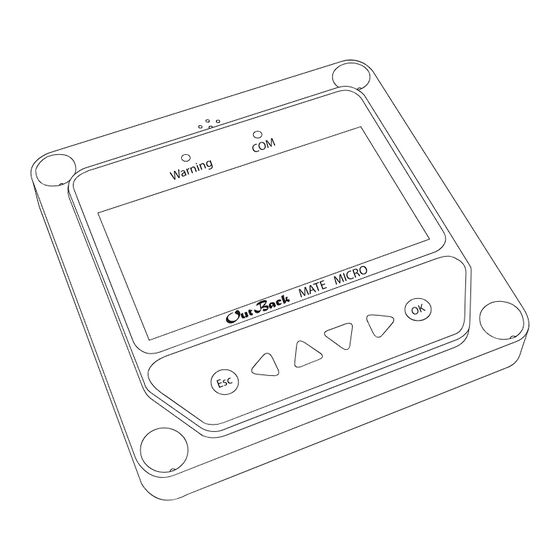
Product Features Product Features Communication Alarm Indicator RS485 Communication and Power Interface Failure Indicator RS485 Display Screen Buttons Figure 5, Front Overview Figure 6, Rear Overview Product Features The failure indicator flashes if the connected device fails. For failure information, Failure Indicator check the controller manual. -
Page 11: Monitoring Screen
Product Features Monitoring Screen Charge Current Icon Battery Status Load Battery Icon Current Icon Day and Load Status Night Icons Icon PV Voltage Load Voltage 17.5V 13.8V 13.8V and Current and Current 15.2A 5.2A 10.0A Values Values Battery Voltage and Current Values Figure 7, Monitoring Screen Overview Monitoring Screen Icons... -
Page 12: Operation
Operation Operation Buttons Figure 8, Outback Mate Micro Buttons From left-to-right, the buttons are: Esc, Left, Up, Down, Right, and OK. Pressing OK will navigate to a subpage, and pressing Esc will take the user back to the previous page. The default page is the “Browse”... -
Page 13: Real-Time Monitoring
Operation Real-Time Monitoring There are 14 screens for the “Monitoring” subpage. See the figure below. Move between the rows by pressing up or down. Move along a row by pressing right or left. 17.5V 13.8V 13.8V 15.2A 5.2A 10.0A FLEXmax 30/40 Jan - 1 - 2015 02:34:33 Char. -
Page 14: Figure 9, Monitoring Screens, Continued
Vol: 0.0V Sta.: DisConnect Cur: 0.0A Fault: Operation Power: 0.0W Char.: PWM/MPPT Controller: Temp.: 25.0°C Sta.: Normal Load Load Vol: 0.0V Sta.: Cur: 0.0A Fault: Power: 0.0W Load Mode Load Mode Information Information Figure 9, Monitoring Screens, continued (06/2016) -
Page 15: Device Information
Operation Device Information The product model, parameters, and SN code of the controller are displayed on the Device Information screen. See the figure below. FLEXmax 30/40 FLEXmax 30/40 Rate.Vol: SN:0002201301200045 Char.Cur: 10.0A Disc.Cur: 2.6A Figure 10, Device Information Screen Test Operation Load switch test operation is conducted on the connected charge controller to determine if the load output is normal. -
Page 16: Control Parameters
Operation Control Parameters See the figure below for the scope of the parameters that are available on the Control Parameters page. Batt. Type Temp Comp. Coe Over Volt. Disc Sealed -3mv/°C/2V 16.0V Batt. AH Rated Voltage Charge Limit 15.0V 200AH Over Volt. -
Page 17: Battery Voltage Parameters
Operation Battery Voltage Parameters Notice The parameters in the table below are from a 12V system at 25°C. Multiply this by 2 in 24V systems, 3 in 36V systems, and 4 in 48V systems. Battery Voltage Parameters Battery Charging Setting Sealed Flooded User... -
Page 18: Load Setting
Operation Load Setting The Load Setting page is used to set the four load working modes of the charge controller: Manual Light On / Off Light On+ Timer Time Control Manual Control Manual Control √ Light On/O Default: On Light On+ Timer Time Control Manual Control Light On/Off... -
Page 19: Figure 14, Light On/Off Working Time
Operation Light On/Off Mode Function Light On Voltage When the input voltage of the solar module is lower than the Light On voltage, the load output is turned (Night Threshold) on automatically, given that the battery capacity is sufficient and there are no abnormal conditions. Light Off Voltage When the input voltage of the solar module is higher than the Light Off voltage, the load ouput is (Day Threshold) -
Page 20: Device Parameter
Operation Time Control Mode Function The On/Off time of the load is controlled through the real-time clock Working Time 1 is the Working Time 1(T1) mode. compulsory working time for the load, while Working Time 2 is optional. Working Time 2 (T2) Working Time 2 provides a dual timer control function of the load. Table 9, Time Control Device Parameter The Device Parameter page allows the user to check/modify the following charge controller data:... -
Page 21: Device Password
Operation Device Password Notice The default password is 000000. The password of the charge controller can be modified via the Device Password page. The password is a 6-digit figure which is required before any modifications to any of the following pages: »... -
Page 22: Failure Information
Operation Failure Information The current failure information of the charge controller can be checked via the Failure Information page. A maximum of 15 failure messages can be displayed. When the failures are eliminated, the corresponding failure information on the display will also be eliminated. -
Page 23: Meter Parameter
Operation Meter Parameter The meter model, software, hardware, and SN NO. version can be checked via the Meter Parameter page. The following three parameters can also be modified: » Switch Pages » Backlight » Audible Alarm Meter Para. Meter Para. Type: Mate Micro Sw-Pages:000S Ver: V1.00+V1.00... -
Page 24: Technical Specifications
Technical Specifications Technical Specifications Technical Specifications Electrical Specifications Backlight and Acoustic Alarm (ON) <65mA Power Consumption Backlight ON <23mA Backlight OFF <15mA Mechanical Specifications Faceplate Dimensions 98 x 98mm Frame Dimensions 114 x 114mm Connector Type RJ45 Meter Cable Standard 2m, Max 50m Meter Weight Simple Package: 0.23Kg, Standard Package: 0.32Kg Environmental Specifications... - Page 26 Outback Power - Europe Hansastrasse 8 D-91126 Schwabach, Germany (06/2016)
Need help?
Do you have a question about the OutBack Power Mate Micro and is the answer not in the manual?
Questions and answers