Table of Contents
Advertisement
Advertisement
Table of Contents

Related Manuals for Ingeteam INGECON SUN PowerMax TL U B 1000 Vdc Series


Summary of Contents for Ingeteam INGECON SUN PowerMax TL U B 1000 Vdc Series
- Page 1 INGECON SUN PowerMax TL U B 1000 Vdc Installation and Operation Manual...
- Page 2 SERVICE CALL CENTERS ABK2027IQE01_A 05/2019 SPAIN Ingeteam Power Technology, S.A. - Energy +34 948 698 715 GERMANY Ingeteam GmbH +49 899 965 3825 FRANCE Ingeteam SAS +33 820 363 749 ITALY Ingeteam S.r.l. +39 0546 651 524 CZECH REPUBLIC Ingeteam, a.s.
- Page 3 Ingeteam INGECON SUN PowerMax TL U B 1000 Vdc Installation and Operation Manual ABK2027IQE01_A - Installation and Operation Manual...
- Page 4 Ingeteam The copy, distribution or use of this document or of its content requires written authorisation. Any breach thereof will be reported for damages. All rights reserved including those of patent rights or design registration. The conformity of the document content with the hardware described has been checked. However, discrepancies may exist. Liability will not be assumed for total concordance.
- Page 5 Important safety instructions Ingeteam Important safety instructions This section describes the safety warnings and the personal protective equipment and symbols used in the unit. Safety conditions General warnings DANGER Opening the enclosure does not imply there is no voltage inside.
-
Page 6: Important Safety Instructions
Ingeteam Important safety instructions Potential hazards for people DANGER Electric shock. The equipment may remain charged after disconnecting the PV array, grid power and auxiliary power. Carefully follow the mandatory steps in the manual for removing the voltage. Explosion. There is a very low risk of explosion in very specific cases of malfunction. -
Page 7: Personal Protective Equipment
Important safety instructions Ingeteam Personal Protective Equipment When working on the unit, use the following safety equipment recommended by Ingeteam as a minimum. Name Explanation Safety footwear In compliance with standard ASTM F2413-05 In compliance with standard ANSI/ISEA Z89.1-2009, wherever there are... - Page 8 Ingeteam Important safety instructions DANGER RISK OF ELECTRIC SHOCK RISQUE DE CHOC ÉLECTRIQUE FROM ENERGY STORED IN DÛ À L’ÉNERGIE STOCKÉE DANS CAPACITOR. LE CONDENSATEUR Do not remove cover until 10 minutes Apres avoir déconnecté toutes les after disconnecting all sources of sources d’alimentation, attendre 10...
-
Page 9: Table Of Contents
Contents Ingeteam Contents Important safety instructions ........................5 Safety conditions ........................... 5 Personal Protective Equipment ....................... 7 Symbols on the units ..........................7 Contents ..............................9 1. About this manual ..........................12 1.1. Scope of application ........................12 1.2. Recipients ........................... 12 1.3. -
Page 10: Contents
Ingeteam Contents 6.7. Requirements for DC feed fuses ....................49 6.8. Requirements for transformers ...................... 52 6.8.1. Grid connection transformer ....................52 6.8.2. Auxiliary transformer ......................54 6.9. Measuring equipment connected to the power grid ................55 7. Installing the unit ..........................56 7.1. - Page 11 Contents Ingeteam 16. AC connection ..........................104 16.1. Safety instructions for the AC connection ................... 104 16.2. Connection area ........................104 16.3. Connecting the AC phases via busbars ..................109 16.3.1. Requirements for the AC phase connection busbars ............109 16.3.2.
- Page 12 Ingeteam Contents 22.4. Corrective replacement tasks ..................... 163 22.4.1. Replacement of arrestors ....................164 22.4.2. Replacement of relays ...................... 164 22.4.3. AC thermomagnetic switch replacement ................164 22.4.4. Electrical cards of the unit ....................164 22.4.5. Replacement of the power phase ..................164 22.4.6.
-
Page 13: About This Manual
The purpose of this manual is to describe the INGECON SUN PowerMax TL U B units and to provide appropriate information for their correct reception, installation, start-up, maintenance and operation. You can download the latest version of this Manual from the website www.ingeteam.com. 1.1. Scope of application... -
Page 14: Unit Description
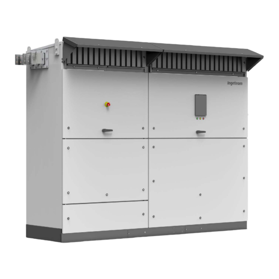
Ingeteam Unit description 2. Unit description 2.1. Overview An inverter is an electronic unit used to convert direct current to alternating current. The function of these units is to convert the direct current generated by PV solar panels to alternating current and so enable it to be fed to the electricity grid. -
Page 15: Available Optional Kits
Unit description Ingeteam 2.4. Available optional kits These units can incorporate the following optional, by order, kits: • DC fuses • DC type I + II natural surge arrester • Monitoring of DC input currents • Ground connection of the PV array •... - Page 16 The maximum consumption is 4250 W (25 A). PV array depolarizer The polarization of the photovoltaic panels may become degraded (Potential Induced Degradation, PID). Ingeteam offers an optional PV array depolarizer that induces the necessary voltage to revert these effects. DANGER When the PV array generates low voltage (nighttime or other situations) this kit generates a voltage of 500 Vdc...
-
Page 17: Options
Unit description Ingeteam Ancillary services feeder In the event of absence of plant grid power, this kit allows to supply the Low Voltage system, so that the inverter will supply the ancillary services as long as there is voltage in the photovoltaic panels and the inverter firmware has been configured for this. -
Page 18: Remote Control For Dc Switch And Ac Thermomagnetic Circuit Breaker
Ingeteam Unit description 2.5.2. Remote control for DC switch and AC thermomagnetic circuit breaker It enables remote manual stop (opening) of the DC switch and the AC thermomagnetic circuit breaker via a normally closed voltage-free contact. When the contact is opened it changes the unit's status to manual stop and remotely trips the DC switch and the AC thermomagnetic circuit breaker. -
Page 19: Dcac Connections Module
Unit description Ingeteam 2.6.1. DCAC connections module -X26 -X33 -X32 -X31 -X30 -X29 -X28 -X27 1 ... 4 1 ... 9 1 ... 9 1 ... 9 1 ... 9 1 ... 9 1 ... 9 1 ... 6 -RVDC... - Page 20 Ingeteam Unit description -TOFS (WH) -TBUSD (WH) -HR* -CMC Component Description Component Description -TOFS (WH) Synchronization card Motorized DC switch remote control Grid connection relay / insulation fault -HR* Optional Low temperature operating kit. / alarm * Optional Individual waste handling (for more information see section “23. Waste handling”)
- Page 21 Unit description Ingeteam -X49 -K12 -K11 filter -COMM -TVPVM (WH) -TVPVO (WH) Component Description Component Description -COMM Communication accessories -TVPVM PV array voltage meter card (WH) End switch -TVPVO PV array opening voltage meter card (WH) Individual waste handling (for more information see section “23. Waste handling”)
- Page 22 Ingeteam Unit description DC supply ABK2027IQE01_A - Installation and Operation Manual...
- Page 23 Unit description Ingeteam -QDC -RVAC -X41 1 2 3 DC fuses Component Description Component Description -QDC Motorized DC switch -RVAC AC surge arresters AC thermomagnetic circuit breaker ABK2027IQE01_A - Installation and Operation Manual...
- Page 24 Ingeteam Unit description Component Description Component Description AC phase R plate connection AC phase T plate connection AC phase S plate connection Component Description AC neutral connection terminal ABK2027IQE01_A - Installation and Operation Manual...
-
Page 25: Power Module
Unit description Ingeteam 2.6.2. Power module INGECON SUN Control Unit INGECON SUN Power (-CCU) (WH) Supply (-PS) (WH) INGECON SUN LVRT (-CSS) (WH) Component Description Component Description -INGECON SUN Fan. Meter and Control system Control Unit (-CCU) (WH) -INGECON SUN... - Page 26 Ingeteam Unit description Phase T -TMEDBUS (WH) (WH) -X11 -X12 -X13 -X14 -X16 -X17 Phase R (WH) Phase S (WH) 1 ... 4 1 ... 4 1 ... 4 1 ... 4 Component Description Component Description Phase R Converter´s Phase R...
- Page 27 Unit description Ingeteam -X45 -X10 -X44 ABK2027IQE01_A - Installation and Operation Manual...
- Page 28 Ingeteam Unit description -FAN_R -FAN_S -FAN_T -TFAM -FAN_L1 -X18 -X19 -X20 -X21 -X22 -K10 1 ... 4 1 ... 4 1 ... 4 Component Description Component Description -FAN_R Phase R fan -FAN_L1 Coil fan -FAN_S Phase S fan AC thermomagnetic switch control...
-
Page 29: Compliance With Regulations
Unit description Ingeteam (WH) (WH) (WH) (WH) (WH) (WH) Individual waste handling (for more information see section “23. Waste handling”) (WH) 2.7. Compliance with regulations UL1741SA, Rule 21, Rule 14-H Standard for Safety for Inverters, Converters, Controllers and Interconnection System Equipment for Use With... -
Page 30: Emc Requirements
Ingeteam Unit description FCC Part 15 B (class A) EMC tests IEEE 1547.1 IEEE Standard Conformance Test Procedures for Equipment Interconnecting Distributed Resources with Electric Power Systems. 2.8. EMC requirements These units are equipped with the necessary filtering elements to comply with EMC requirements for industrial applications in order to prevent disturbances in other equipment outside the installation. -
Page 31: Dimensions
Unit description Ingeteam 2.12. Dimensions 0 3 7 m i n ( 1 4 0 . 8 3 1 1 0 . 9 i n ( 2 8 1 6 m m 3 m m i n ( 8 2 3 2 . -
Page 32: Electrical Diagram Of The Unit
2.15. Electrical diagram of the system The configuration of the high-voltage winding of the grid connection transformer does not affect the behavior of the unit. Inverter Ingeteam recommends using a transformer with Dy11 connection. ABK2027IQE01_A - Installation and Operation Manual... -
Page 33: Ac Surge Maximum Curve
Unit description Ingeteam 2.16. AC surge maximum curve Both its equipment and auxiliary services are designed to support the following surge curves. [Vp.u] 1.45 1.35 1.25 1.15 1.05 0.3 0.4 Higher surges, both in the value and duration, may cause damage to the equipment. -
Page 34: Configuration Parameters
Ingeteam Unit description 2.17. Configuration parameters DC inputs 750TL U B270 830TL U B300 1000TL U B360 1110TL U B400 1140TL U B410 Range of operating input voltage 397 ~ 820 V 440 ~ 820 V 524 ~ 820 V 580 ~ 820 V 595 ~ 820 V... - Page 35 Unit description Ingeteam Values and times of disconnection of the voltage and frequency protections in the interconnection of the unit with the electrical company (for all equipment) Simulated source Maximum time (s) at 60 Hz before Levels the cessation of the current to the...
-
Page 36: Cooling System
Ingeteam Unit description 2.18. Cooling system The cooling system in these inverters consist in four fans that vent room temperature air to the upper part and remove the hot air from the back. INFO The cooling requirements and necessary flow rate are specified in Section “6.6. Cooling”. -
Page 37: Description Of Cable Inlets
Unit description Ingeteam 2.19. Description of cable inlets These units have wired accesses on the lower part. Wiring options and auxiliary services. Cover Ethernet. M25 packing gland, one hole, with membrane, permitted wiring diameter permitted wiring diameter 0.24 ~ 0.51 in 0.24 ~ 0.51 in (6 ~ 13 mm). -
Page 38: Utility - Interactive Mode Functions
Ingeteam Unit description • Rule 21, Section Hh. (Revision through August 2nd, 2017) for California. • SRD-UL-1741-SA-V1.1 Updated: 9/26/2017 (Rule 14H) for Hawaii. 2.20.2. Utility – Interactive mode functions This mode has the functions typically required by UL1741 before supplement A. They are basically voltage and frequency protections, anti-islanding protection and DC current injection control: •... - Page 39 Unit description Ingeteam Parameters Test Acronym Description Units Defined value 1500 @ 1500 Vdc Output Current Rating 1600 @ 1000 Vdc rated Minimum normal ramp-up rate /sec SS_min rated Maximum normal ramp-up rate /sec SS_max rated Minimum output current Ramp Rate Accuracy...
-
Page 40: Active And Reactive Power Capacities
Ingeteam Unit description Parameters Test Acronym Description Units Defined value Rated power Output Power Rating depending on model rated Voltage range AC voltage range with function enabled depending on model Nominal AC voltage Nominal AC voltage depending on model AC voltage accuracy... -
Page 41: Equipment Reception
Equipment reception Ingeteam 3. Equipment reception 3.1. Packaging symbols Bear in mind the following symbols present on the packaging of the unit: Move transport packaging with this side up. Do not use sharp tools to open the shipping packaging. Prevent the unit from becoming wet. -
Page 42: Storage
Failure to follow the instructions in this section may lead to damage to the unit. Ingeteam accepts no liability for damage resulting from the failure to follow these instructions. If the unit is not installed immediately after reception, the following points should be taken into account in order to avoid damage: •... -
Page 43: Equipment Transport
You must protect the unit, during transport, from mechanical knocks, vibrations, water splashes (rain) and any other product or situation which may damage it or alter its behavior. Failure to observe these instructions may lead to loss of warranty on the product, for which Ingeteam is not responsible. -
Page 44: Preparation For Installing The Unit
• Installations must be in accordance with laws, regulations, codes and standards applicable in the jurisdiction of the location. Ingeteam accepts no liability for the compliance or non-compliance with these laws, regulations, codes and standards. •... -
Page 45: Environment
If installing the Low temperature operating kit, the minimum operating temperature is -22 ºF (-30 ºC). Operation of the inverter at temperatures greater than 122 ºF (50 ºC) should only occur occasionally and not permanently. Ingeteam is not responsible for the consequences to the unit resulting from operating it at temperatures higher than 122 ºF (50 ºC). -
Page 46: Fixing Surface Area
Ingeteam Preparation for installing the unit 6.4. Fixing surface area The unit's excessive weight requires a firm base for support, completely horizontal and leveled, assuring proper water drainage and avoiding water accumulation. To perform the installation calculations it is necessary to take into account the loads that affect the environment conditions, according to the country's regulations. - Page 47 Preparation for installing the unit Ingeteam With bottom cover Top view 2189 N 4363 N 3225 N 35.4 in (899 mm) 1930 N 4025 N 3010 N 39.29 in (998 mm) 33.11 in (841 mm) 107.82 in (2,739 mm) i = 11.81 in (300 mm)
-
Page 48: Anti-Humidity Elements
Ingeteam Preparation for installing the unit ≥ M10 ≥ 2.83 in (72 mm) 6.5. Anti-humidity elements Before making the connections, you need to remove the anti-humidity elements from the unit The following figure displays the location of said elements. 6.6. Cooling... - Page 49 /h) per installed inverter. • These inverters come with filters in the air inlet. Ingeteam recommends a filter in the air vent inlet of the class G4 cabin (in accordance to the EN779 standard). We recommend a separation of 1.18 in (3 cm) between the air inlet vent and the filter.
-
Page 50: Requirements For Dc Feed Fuses
/h) per inverter is required. • These inverters come with filters in the air inlet. Ingeteam recommends a filter in the air vent inlet of the class G4 cabin (in accordance to the EN779 standard). We recommend a separation of 1.18 in (3 cm) between the air inlet vent and the filter. - Page 51 Preparation for installing the unit Ingeteam • gPV class. • Rated current of 50 A ~ 630 A, depending on the specifications of the unit. Fuses of the following sizes and formats are allowed: Recommended size Number of inputs Number of fuses...
- Page 52 Ingeteam Preparation for installing the unit 3L Mechanical specifications max. 0.24 in (6 mm) max. 5.12 in (130 mm) max. 2.91 in (74 mm) max. 8.07 in (205 mm) max. 6.85 in (174 mm) max. 5.28 in (134 mm) These inverters can be equipped with fuse holders from different manufacturers, that is why in the previous figure they indicate as reference the minimum measures of the fuse holders that can be used.
-
Page 53: Requirements For Transformers
Preparation for installing the unit Ingeteam Fuse holder base Siba Fuse size Rated current Rated voltage size With indicator Without an indicator and adapter for microswitch 20 028 28.50 20 028 29.50 50 A 20 028 28.63 20 028 29.63 63 A 20 028 28.80... - Page 54 Ingeteam Preparation for installing the unit If connecting the equipment to the transformer's same low voltage winding, these must be synchronized. These equipment have all the necessary elements to synchronize up to four inverters. Low Voltage / Medium Voltage INFO See section “13.
-
Page 55: Auxiliary Transformer
Ingeteam accepts no liability for any consequences arising from non-compliance with these instructions. It is possible to install the auxiliary services kit, and if you prefer you may install an auxiliary transformer acquired from third parties. -
Page 56: Measuring Equipment Connected To The Power Grid
Ingeteam Preparation for installing the unit The technical requirements of the auxiliary transformer are: • The transformer’s power should be suitable for the loads connected to it, taking the site environmental conditions into account. The minimum power value is 4700 VA per inverter. -
Page 57: Installing The Unit
The ventilation system protection must remain open whenever the unit is running. Failing to do this may cause faults. Ingeteam accepts no liability for the consequences of non-compliance with this warning. Before starting the connections, the ventilation system protections must be opened. To do this, take the following... - Page 58 Ingeteam Installing the unit For each of the front side protections, release the two frontal locks turning them counterclockwise one quarter of the way using the key provided. Open the protection and extend the folding supports on both ends. ABK2027IQE01_A - Installation and Operation Manual...
- Page 59 Installing the unit Ingeteam Fasten the two supports using bolts. If the inverter is fitted with a sand trap kit, remove the grilles from the rear side. The protections in the rear ventilation system are removed together with these. ABK2027IQE01_A - Installation and Operation Manual...
- Page 60 Ingeteam Installing the unit Insert the protections from both ventilation ducts in the receptacle shown in the following figure. Close both grilles. ABK2027IQE01_A - Installation and Operation Manual...
-
Page 61: Connection Process Sequence
Installing the unit Ingeteam 7.3. Connection process sequence Once the unit has been mounted in its final position and has been solidly secured, make the electrical connections to it. The order is as follows: Ground connection. DC connection. Connection of the PV array grounding kit [optional]. -
Page 62: Ground Connection
In order to keep the nuts and bolts of the unit in good condition it is important to make sure there is no dirt or shavings in the threads when screwing them in and apply a suitable lubricant. Ingeteam accepts no liability for any damages caused by an incorrect connection. ABK2027IQE01_A - Installation and Operation Manual... -
Page 63: Connection Area
• The selected breaking capacity on the AC thermomagnetic circuit breaker AC is 65 kA. • Ingeteam accepts no responsibility for the installation of the inverter in installations with a higher than specified short-circuit current. • The short-circuit current delivered by the inverter is considerably lower than the breaking capacity of the AC thermomagnetic circuit breaker. -
Page 64: Making The Ground Connections Via A Terminal
Clean the contact surfaces on both the terminal and the connection bar with a clean cloth and ethanol. Connect the terminal to the connection bar using the bolts and washers supplied by Ingeteam with the unit, respecting the torque specified. -
Page 65: Dc Connection
In order to keep the nuts and bolts of the unit in good condition it is important to make sure there is no dirt or shavings in the threads when screwing them in and apply a suitable lubricant. The polarities indicated in the following figure must be followed. Ingeteam accepts no liability for any damages caused by an incorrect connection. -
Page 66: Connection Area
* The fasteners are supplied factory lubricated with Loctite 8009. If necessary, apply the same lubricant again or another compatible one. ** To facilitate handling of the wiring, Ingeteam recommends using more than one smaller gauge cable instead of one large gauge cable. For example, it is preferable to use two 400 kcmil cables instead of one 750 kcmil cable. - Page 67 DC connection Ingeteam DC connection via a terminal with one hole M12 hex head bolt. M12 washer. Terminal. Hole diameter of M12, maximum thickness of 0.39 in (10 mm), maximum width of 1.3 in (33 mm). Busbar. When using a single hole terminal, use only the top hole in the connection position of the plate.
- Page 68 Ingeteam DC connection DC connection via a terminal with two holes M12 hex head bolt. M12 washer. Terminal. Hole diameter of M12, maximum thickness of 0.39 in (10 mm), maximum width of 1.3 in (33 mm), vertical distance between holes of 13/4 in (44.5 mm). Busbar.
-
Page 69: Dc Connection Process
Clean the contact surfaces on both the terminal and the connection bar with a clean cloth and ethanol. Connect the terminal to the busbar via the bolts and washers supplied by Ingeteam upon delivery of the unit, respecting the indicated tightening torque and polarities indicated in the following points of this section, relative to the fuses installed (see figures below). - Page 70 Ingeteam DC connection Units without fuses To connect the DC, respect the indicated polarities in the following figure: Positive pole Negative pole ABK2027IQE01_A - Installation and Operation Manual...
- Page 71 DC connection Ingeteam Units with fuses in the positive pole To connect the DC, respect the polarities and the order of the connection busbars specified in the following figure: Positive pole Negative pole The number of fuses and connections varies as a function of the selected configuration.
- Page 72 Ingeteam DC connection Units with fuses in the positive and negative poles To connect the DC, respect the polarities and the order of the connection busbars specified in the following figure: Positive pole Negative pole The number of fuses and connections varies as a function of the selected configuration.
- Page 73 DC connection Ingeteam Units with Integrated DC combiner box with fuses on the positive pole To connect the DC, respect the polarities and the order of the connection busbars specified in the following figure: Positive pole Negative pole Busbar if several inverters are connected to the same winding (see section “10.2.
-
Page 74: Connection/Disconnection Of The Dc Fuses
Ingeteam DC connection 9.5. Connection/disconnection of the DC fuses After connecting the cables, the DC fuses should be fitted. To install, follow this order: Open the folding door of the DCAC connections module. Remove the mid-frontal cover. CAUTION To install fuses in their holders, use a tool designed for this task, as well as for removing them. -
Page 75: Connection Of The Pv Array Grounding Kit [Optional]
The connection of the grounded poles of the inverters must be done using a copper or aluminum wire of 35 mm 50 mm and at least 1000 V insulation (not supplied by Ingeteam) and fuses (supplied by Ingeteam). The purpose of these fuses is not to protect the ground connection but to offer the installer the possibility of insulating the units in a simple way in order to carry out maintenance tasks. - Page 76 Ingeteam Connection of the PV array grounding kit [optional] Connect the grounded pole of each unit through a 35 mm section cable with 1000/1500 V insulation. This connection can be done through the cable grommets provided in the bases of the units in question.
- Page 77 Connection of the PV array grounding kit [optional] Ingeteam On the other inverter, remove the end of line resistor from the wiring between -X26.3A y -X26.4A and connect the other end of the CAN cable with the color code described in the diagram to -X26.1B, -X26.2B, -X26.3B, -X26.4B.
-
Page 78: Three Units Connected To The Same Transformer Winding
Ingeteam Connection of the PV array grounding kit [optional] -INV1 (-TSGND) -INV2 -Rfin -X26 -X26 -Rfout -INV1 (-TSGND) -INV2 Yellow Green -Rfin White Brown -X26 -X26 -Rfout -CAN_1 10.2.2. Three units connected to the same transformer winding When connecting three units to the same transformer winding, the grounding of the system must be unique and shared, as otherwise there could be currents flowing through the different ground connections. - Page 79 Connection of the PV array grounding kit [optional] Ingeteam Connect the CAN communication buses from the inverters using the cable provided. To connect the communication buses, carry out the following process: Inverter 1 Inverter 2 Inverter 3 On the inverter with -TSGND, remove the end of line resistor from the wiring between -X26.3D and -X26.4D and connect the CAN cable with the color code described in the diagram to -X26.1C,...
- Page 80 Ingeteam Connection of the PV array grounding kit [optional] -INV1 -INV2 -INV3 -QDC -QDC -QDC -FG1 -FG2 -FG3 -TSGND -PV1 -PV2 -PV3 ABK2027IQE01_A - Installation and Operation Manual...
-
Page 81: Operating Procedure On Grounded Inverters
Connection of the PV array grounding kit [optional] Ingeteam -INV1 (-TSGND) -INV2 -INV3 -Rfin -X26 -X26 -X26 -Rfout -INV1 (-TSGND) -INV2 -INV3 Yellow Yellow Green Green -Rfin White White Brown Brown -X26 -X26 -X26 -Rfout -CAN_1 -CAN_2 10.3. Operating procedure on grounded inverters The purpose of this section is to describe in detail the procedure for working safely with grounded inverters. -
Page 82: Inverters With -Tsgnd Card
Ingeteam Connection of the PV array grounding kit [optional] In the following diagram the inverter with -TSGND and the inverter without -TSGND are marked in a system with two inverters against one transformer: -INV1 -INV2 -QDC -QDC -FG1 -TSGND -PV1... - Page 83 Connection of the PV array grounding kit [optional] Ingeteam inverter with the -TSGND card and working on it, it is recommended to stop the other units connected to the same transformer winding, if any, via the display. If the event that they are not stopped via the display, they will stop when the ground connection in the inverter with the -TSGND card is temporarily removed, as they will detect an insulation fault in the grounded pole.
-
Page 84: Inverters Without -Tsgnd Card
Ingeteam Connection of the PV array grounding kit [optional] 10.3.2. Inverters without -TSGND card DANGER All the operations described below must always and without exception be performed following the five golden rules. Operations upstream of the DC switch (inverter side) The motorized switch on the units opens both the positive pole and the negative pole in the PV array, leaving the inverter completely isolated. -
Page 85: Connecting Auxiliary Services
In order to keep the nuts and bolts of the unit in good condition it is important to make sure there is no dirt or shavings in the threads when screwing them in and apply a suitable lubricant. Ingeteam accepts no liability for any damages caused by an incorrect connection. 11.2. Connection area The terminal block for making the auxiliary AC connections is -XAUX located in DCAC connections module. - Page 86 Ingeteam Connecting auxiliary services Crimp the wire ends according to the wire gauge being used. Open the terminal. The terminals used in this terminal strip are of the clamp type. To insert the cable into the desired position press with a flat head screwdriver, insert the cable and then remove the screwdriver.
-
Page 87: Connection Of The Communication Accessories
In order to keep the nuts and bolts of the unit in good condition it is important to make sure there is no dirt or shavings in the threads when screwing them in and apply a suitable lubricant. Ingeteam accepts no liability for any damages caused by an incorrect connection. ABK2027IQE01_A - Installation and Operation Manual... -
Page 88: Ethernet Communication
For plant control, connect via port A. If the monitoring kit for DC input currents is installed, the communications for said kit shall be connected via port B. To make the connection of various inverters you must install a switch. Ingeteam offers the optional switch by order upon the delivery of the unit. - Page 89 Connection of the communication accessories Ingeteam After connecting the Ethernet cables, it must be led through the ducts on the unit towards the dedicated cable entrances (see the following diagram and section “2.19. Description of cable inlets”). The communication hardware allows the configuration of two Ethernet interfaces with two different IP addresses for the same inverter.
-
Page 90: Communication Via 3G
Ingeteam Connection of the communication accessories INFO For more information, see the Ethernet communications manual, available at www.ingeteam.com. 12.3. Communication via 3G Optionally, the inverters can include hardware to communicate via 3G, located on the side of the upper assembly panel of the DCAC connections module. - Page 91 Connection of the communication accessories Ingeteam To make the connection of various inverters you must install a switch. Ingeteam offers the optional switch by order upon the delivery of the unit. Inverter internal wiring Wiring to do by installer between inverters...
-
Page 92: Connection Of The Dcac Connections Module
Connection of the DCAC connections module 13. Connection of the DCAC connections module If several inverters are connected to the same transformer, you need to synchronize them. Ingeteam recommends synchronizing inverters even if connected to independent windings. The inverters have as standard all the necessary elements for synchronization (electronic card and fiber cables). -
Page 93: Wiring Requirements For The Synchronization Connection
Connection of the DCAC connections module Ingeteam 13.3. Wiring requirements for the synchronization connection Use the cable supplied by Ingeteam. 13.4. Synchronization connection process Open the folding door of the DCAC connections module. Connect the fibers in the synchronization cards following the diagrams displayed in section “13.4.1. -
Page 94: Configuring The Synchronization
Ingeteam Connection of the DCAC connections module 13.4.1. Configuring the synchronization You can synchronize up to four inverters. This depends on the number of synchronized inverters, following the connection diagrams from this section. For synchronization, one of the inverters must be set as master and the rest as slaves. The configuration as master or slave is done via the synchronization card of each inverter. - Page 95 Connection of the DCAC connections module Ingeteam Synchronization of two inverters To perform the synchronization of two inverters wired according to the following diagram, using the fiber optics provided by Ingeteam. Master Slave a b c a b c Inverter internal wiring...
- Page 96 In this section we indicate the diagram to perform the synchronization of three inverters. Wire according to the diagram using the fiber optics cables provided by Ingeteam. Ingeteam provides one additional fiber optics cable with the aim of making the synchronization system redundant. Ingeteam recommends the pre-installation of said wiring, without performing a connection. When confronting an...
- Page 97 Connection of the DCAC connections module Ingeteam Ingeteam provides one additional fiber optics cable with the aim of making the synchronization system redundant. Ingeteam recommends the pre-installation of said wiring, without performing a connection. When confronting an incident of an inverter configured as master, you can reconfigure the system selecting another inverter as master in...
-
Page 98: Connection Options
In order to keep the nuts and bolts of the unit in good condition it is important to make sure there is no dirt or shavings in the threads when screwing them in and apply a suitable lubricant. Ingeteam accepts no liability for any damages caused by an incorrect connection. ABK2027IQE01_A - Installation and Operation Manual... -
Page 99: Connection Area
Connection options Ingeteam 14.2. Connection area -X38 1 ... 4 14.3. Wiring requirements for connecting optional equipment • The wiring for connecting the options needs to be carried out by the client. • All cables must withstand temperatures greater than +194 °F (+90 °C) and comply with the National Electrical Code ANSI/NFPA 70. - Page 100 Ingeteam Connection options The normally closed, voltage-free contacts to monitor are installed between the two free positions on terminal -X38.1, removing the vertical link. -X38.1 • Open contact: fault in the monitored component. • Closed contact: no fault at monitored component.
-
Page 101: Inverter Remote Manual Stop Connection Process
Connection options Ingeteam Remove the vertical link. 14.5. Inverter remote manual stop connection process CAUTION It is not possible to use the same contact to perform the manual stop of several units. The motorized DC switch and the AC thermomagnetic circuit breaker have a limited number of operating cycles, so excessive use may lead to premature wear. - Page 102 Ingeteam Connection options CAUTION The maximum length permitted for the wiring of this contact is 10 meters. If necessary to use longer wiring, add an intermediate relay as shown in the following figure. ETAP New relay To make the connection, follow the following steps: Strip the cables.
-
Page 103: Optional Kit Connection
Normally closed and open contacts must be prepared for 230 VAC 50/60 Hz and a 10 A current. Ingeteam offers the possibility of monitoring the AC circuit breaker status (open or closed) via a normally open, power free contact with a maximum of 230 VAC and 10 A. -
Page 104: Connecting The Ancillary Services Feeder Kit
Ingeteam Optional kit connection Max 230 VAC Max 10 A -X40.2 15.3. Connecting the ancillary services feeder kit The dimensions of the cables to connect this kit must be studied by the installer according to the requirements and specifications of the PV plant. Connect the cable to the terminals shown in the following figure. -
Page 105: Ac Connection
To find the different components listed below, consult Section “2.6. Location of components”. Refer to Section “Important safety instructions” and the safety paragraph in this section before operating the equipment. For other configurations different to those described in this document, please contact Ingeteam. 16.1. Safety instructions for the AC connection DANGER Before performing the connection, check there is no voltage in the AC wiring. - Page 106 Ingeteam AC connection Units with busbars on the left Units with busbars on the right Upper busbars for busbar connection The AC phase busbars are located in the upper left or right side, depending on the unit configuration. The connection is made via the flexible busbars.
- Page 107 AC connection Ingeteam The dimensions of the inverter busbars are as follows: 0.78 in (20 mm) 0.55 in (14 mm) 1.97 in (50 mm) 7.08 in (180 mm) ABK2027IQE01_A - Installation and Operation Manual...
- Page 108 Ingeteam AC connection Medium height busbars for direct connection to transformer busbars The AC phase busbars are located on the left or right side, depending on the unit configuration. The connection is made directly to the transformer busbars. The dimensions of the inverter busbars are as follows: 0.39 in (10 mm)
- Page 109 AC connection Ingeteam The AC phase busbars are located on the left or right side, depending on the unit configuration, and the cable entry is done from the lower part of the enclosure that protects the connection. The following figure represents a cross- section view of the enclosure.
-
Page 110: Connecting The Ac Phases Via Busbars
16.3. Connecting the AC phases via busbars 16.3.1. Requirements for the AC phase connection busbars If using busbars for the AC connection, the requirements must be established with Ingeteam according to the characteristics of the PV plant. 16.3.2. Connection process Proceed in the following order for each phase: Clean the contact surfaces on both the terminal and the busbar with a clean cloth and ethanol. -
Page 111: Connecting The Ac Phases Via Terminals
AC connection Ingeteam To connect to transformers with the low-voltage winding in delta or to transformers without the neutral accessible, it is necessary to change the position of a wire in the -CCU. Connect the cable going to -J10.1 (labeled as N on the card) from the -CCU in J10.2. - Page 112 6 AWG lubrication) * To facilitate handling of the wiring, Ingeteam recommends using more than one smaller gauge cable instead of one large gauge cable. For example, it is preferable to use two 400 kcmil cables instead of one 750 kcmil cable. Phase connection via a terminal with one hole M12 DIN 933 screw.
- Page 113 AC connection Ingeteam Phase connection via two terminals with one hole M12 DIN 933 screw. M12 NFE-25 511 M washer. Terminal. Hole diameter of M12, maximum thickness of 0.39 in (10 mm), maximum width of 1.3 in (33 mm). Busbar. When using a single hole terminal, use only the top hole in the connection position of the plate.
-
Page 114: Ac Phases Connection Process Via A Terminal
Ingeteam AC connection Phase connection via two terminals with two holes M12 DIN 933 screw. M12 NFE-25 511 M washer. Terminal. Diameter of the M12 hole, maximum thickness of 0.39 in (10 mm), maximum width of 1.3 in (33 mm), vertical distance between holes of 13/4 in (44.5 mm). -
Page 115: Connecting The Ac Neutral
AC connection Ingeteam Connect the terminals using the bolts, nuts and washers specified by Ingeteam, applying a tightening torque of 42 Nm with NLGI 1 anti-seize lubrication. Ensure the correct connection of the cable and terminal. To connect to transformers with the low-voltage winding in delta or to transformers without the neutral accessible, it is necessary to change the position of a wire in the -CCU. -
Page 116: Connecting The Medium Voltage Switchgear Emergency Trip
Ingeteam AC connection Units connected to transformers with the low-voltage side in delta connection or star without accessible neutral To connect to transformers with the low-voltage winding in delta or to transformers without the neutral accessible, it is necessary to change the position of a wire in the -CCU. -
Page 117: Configuring The Optional Dc Input Current Monitoring Kit
Configuring the optional DC input current monitoring kit Ingeteam 17. Configuring the optional DC input current monitoring kit The main function of the kit is to permanently monitor the current flowing through each multiple input in the inverter, in order to detect abnormal currents due to faults in the PV array and/or protection elements (fuses). - Page 118 Ingeteam Configuring the optional DC input current monitoring kit Switch Node number ABK2027IQE01_A - Installation and Operation Manual...
- Page 119 Configuring the optional DC input current monitoring kit Ingeteam Switch Node number ABK2027IQE01_A - Installation and Operation Manual...
-
Page 120: Configuring The Measurement String Numbers
17.2. Configuring the measurement string numbers INFO The string numbers are factory set. In exceptional cases it may be necessary to modify this setting. To do this, please contact Ingeteam. 17.3. Monitoring INFO The communications connection of the kit shall be done via Ethernet port B in the unit. For plant control, connect via port A. -
Page 121: Communication Via Modbus Registries
INFO To obtain information about how this information is structured and how to access it through the MODBUS protocol, request document AAV1089IMB04 from Ingeteam. 17.3.2. Communication with the unit's display It is possible to view the data registered by the kit through the Monitoring menu on the inverter's display, in option Input DC measurement. - Page 122 Ingeteam Configuring the optional DC input current monitoring kit Code Alarm Description 0x0002 Blown fuse in series 2 alarm Blown fuse in series 2 0x0004 Blown fuse in series 3 alarm Blown fuse in series 3 0x0008 Blown fuse in series 4 alarm...
-
Page 123: Commissioning
Commissioning Ingeteam 18. Commissioning This chapter details the process for commissioning the unit. INFO To find the different components listed below, consult Section “2.6. Location of components”. Refer to Section “Important safety instructions” and the safety paragraph in this section before operating the equipment. - Page 124 Ingeteam Commissioning Exceptionally, and only for maintenance or servicing tasks, the DC switch can be operated manually. To perform this action, turn the operating mode selector 90º counter-clockwise. Upon selecting manual mode, it frees access for the installation of the switch opening rotary knob.
-
Page 125: Shutting Down
Commissioning Ingeteam CAUTION Manual operation of the DC switch limits unit safety and protection. Ingeteam accepts no liability for damage resulting from this action. INFO By default, the DC switch must always be in AUTO. Otherwise an alarm is activated. -
Page 126: Opening The Ventilation System Protection
18.4.1. Start-up CAUTION Failure to comply with the verification tasks described releases Ingeteam from any liability for possible damage to the system or the inverter itself caused by such failure. Once the wiring has been completed and all components of the inverter have been checked, start up the unit. Take the following steps in the order they appear: Perform the checks indicated in Section “18.1.1. -
Page 127: Checking And Measurement
18.4.2. Checking and measurement INFO Ingeteam recommends checking the waveform of the current generated in the three phases using an ammeter clamp. Use the PPE listed in section “Personal Protective Equipment” to get this reading. During initial connection to the grid, Ingeteam recommends monitoring the temperatures inside the unit to check correct operation of the cooling system. -
Page 128: Display Control
Ingeteam Display control 19. Display control These inverters incorporate a display and keypad unit to interface with the installer and the user. This interface allows the display of the main internal parameters and the configuration of the entire system during installation. -
Page 129: Display
Display control Ingeteam 19.2. Display 2018/07/09 2018/07/09 11:23 11:23 Current date, YYYY-MM-DD. Power reduction percentage and reason for this reduction*. Current time, hh:mm. If there is a loss of communication between the inverter and the display, the two points stop blinking. -
Page 130: Menu Structure
Ingeteam Display control 19.3. Menu structure Daily power graph Start screen Energy graph for the last 24 days Main menu Monitoring Pac, Qac, Sac, PhiCos Vac1, Vac2, Vac3, Fac Iac1, Iac2, Iac3, Riso Pdc, Vdc, Vbus, Idc Temp_ph_R, Temp_ph_S, Temp_ph_T, Temp_ind... -
Page 131: Daily Power Graph
Display control Ingeteam 19.4. Daily power graph 2018/07/09 2018/07/09 20:17 20:17 In this screen you can consult the daily power graph. The daily energy values (Ed), from the first connection of the day to the time of the query, the total accumulated energy (Et) and the power (P) are also listed. -
Page 132: Monitoring
Ingeteam Display control 19.6.1. Monitoring This menu includes a series of screens which show the main variables being monitored. To move between the different screens use the keys The structure and interpretation of the variables of this menu are shown below: Inverter AC power, in kilowatts. -
Page 133: Events
Display control Ingeteam String13 Current string 13. String14 Current string 14. String15 Current string 15. Total Energy Total energy fed through the inverter throughout its useful life. Time Total time that the inverter has been feeding the grid. Connections Total number of grid connections. - Page 134 Ingeteam Display control Alarm Name Variable Code LED Lighting Description The voltage variation in the DC bus exceeds a maximum value. The DC voltage under normal operation remains PWM HW fault 0x1000 constant, with changes due to the control of the maximum power point.
- Page 135 Display control Ingeteam Alarm Name Variable Code LED Lighting Description The purpose of the surge arrester protection alarm is to monitor the status of the unit's AC and SC surge arresters. Arrestors 0x0020 The monitoring signal of the AC and SC surge arresters is serialized.
-
Page 136: Start/Stop
Ingeteam Display control Alarm Name Variable Code LED Lighting Description Fault in the CSS system. CSS system or 0x0800 voltage sag system Replace the CSS or inspect the wiring. Communication error between the CCU and the devices connected through the CAN bus, which are: •... -
Page 137: Settings
The settings included within this menu can only be modified by a qualified installer. Ingeteam accepts no liability for incorrect use of the installer password nor the consequences that may arise from incorrect configuration of the unit by the user and / or the installer. -
Page 138: Shutting Down The Unit
The AC switch may not be operated manually under any circumstances. If this warning is not followed, the safety of personnel and equipment cannot be guaranteed. Ingeteam accepts no liability for the consequences of non-compliance with this warning. Use the PPE listed in section “Personal Protective Equipment”. - Page 139 Shutting down the unit Ingeteam Check that the DC switch is in OFF. If the switch has not moved automatically to the OFF position, operate it manually. If manual actions are necessary, wait 10 minutes for the internal capacities to discharge.
- Page 140 Ingeteam Shutting down the unit AC busbar 1 - AC busbar 2 AC busbar 2 - AC busbar 3 AC busbar 1 - AC busbar 3 AC busbar 1 - Ground* AC busbar 2 - Ground* AC busbar 3 - Ground* * Use the metal structure of the inverter as a grounding point, on a part that is not painted.
-
Page 141: Stopping The Inverter From The Display
Shutting down the unit Ingeteam DC 1 - DC 2 DC 2 - DC 3 DC 1 - Ground* DC 2 - Ground* * Use the metal structure of the inverter as a grounding point, on a part that is not painted. -
Page 142: Inverter Shutdown From The Emergency Stop Button
Section “20.1. Process of shutting down the unit”. CAUTION Ingeteam accepts no liability for the consequences of tampering with the safety system. The inverter’s electro-mechanical elements have a limited number of operating cycles for on-load disconnection. -
Page 143: Preventive Protocol In The Event Of Sand/Dust Storms
Ingeteam accepts no liability for the consequences of non-compliance with this warning. Depending on the location of the installation, the units may be subject to sand or dust storms. In the event of an expected storm, follow the protocol below for each inverter. - Page 144 Ingeteam Preventive protocol in the event of sand/dust storms Close the protection and fasten it using the locks provided. Rear ventilation system Remove the grilles in the rear side. ABK2027IQE01_A - Installation and Operation Manual...
- Page 145 Preventive protocol in the event of sand/dust storms Ingeteam Remove the protections for both ventilation ducts from the receptacle shown in the following figure. Insert the protections inside of the grilles. ABK2027IQE01_A - Installation and Operation Manual...
- Page 146 Ingeteam Preventive protocol in the event of sand/dust storms Install the grilles in their positions. Close both grilles. ABK2027IQE01_A - Installation and Operation Manual...
-
Page 147: Maintenance
Maintenance Ingeteam 22. Maintenance Throughout this chapter we will list the maintenance tasks along with preventative and corrective replacements for proper inverter maintenance. INFO To find the different components listed below, consult Section “2.6. Location of components”. Refer to Section “Important safety instructions” and the safety paragraph in this section before operating the equipment. -
Page 148: Frequency Of Maintenance Tasks
Ingeteam Maintenance 22.2.1. Frequency of maintenance tasks CAUTION The maintenance frequency described are established for normal weather conditions. In the event of more severe conditions, the frequency must be increased according to necessity, especially for filter cleaning. Maintenance tasks must be done in the following frequencies. - Page 149 Maintenance Ingeteam Check that there is no moisture inside the unit. If moisture exists, dry before making electrical connections or starting up the unit. Verify the lack of insects and other animals in the unit´s inside. If animals are found within the inverter, take the necessary measures to remove them.
- Page 150 Ingeteam Maintenance Cleaning or replacing filters and sand trap system (action, voltage-free) To remove the filters, follow these instructions. The process is the same even if the inverter does not have the sand trap system installed. Using the key provided, unlock the front locks on the filter holder tray.
- Page 151 Maintenance Ingeteam Remove the filter and clean it using compressed air. If necessary, wash with water at a temperature below 70 ºC. If the filter is in bad condition, replace it. Filters used on the unit. Self-extinguishing filters with synthetic fibers 150 gr/m .
- Page 152 Ingeteam Maintenance Turn the sand trap system slightly. Remove the sand trap system. Clean the sand trap system using compressed air. Vacuum the inside of the unit through the hole where the filter and sand trap system where. To install the filter and sand trap system, follow the instructions in reverse order, paying special care to fit the filter...
- Page 153 Maintenance Ingeteam With the filter holder tray open, install the filter in the lower part of the filter holder, as shown in the following figure. ABK2027IQE01_A - Installation and Operation Manual...
- Page 154 Username: powermaxb Password: Manual The location of the components displayed in the videos may be different. If in doubt, contact Ingeteam. Check via the proper measurement tools that the waveforms in DC and AC are correct. Reasons for stopping and quality of the waveform (check, voltage-free) Download the history of the stops via the INGECON SUN Manager.
-
Page 155: Annual Maintenance Tasks
Maintenance Ingeteam 22.2.4. ANNUAL maintenance tasks Unit housing (inspection, voltage-free) You must carry out a visual check of the condition of the housing, confirming the condition of the locks, doors and handles as well as the fixing of the units to their anchor points. In addition, you must check the condition of the housing for dents, scratches or rust that might degrade the unit or cause it to lose its protection classification. - Page 156 Mechanism. To locate these components, see the AC thermomagnetic circuit breaker operation and maintenance manual. The lubricant recommended by the manufacturer is PLG-322 by N.E.O. For equivalents, please contact Ingeteam. Fuses (check, voltage-free) Check the condition of the various fuses protecting the unit. Check for continuity via a suitable multimeter.
- Page 157 Maintenance Ingeteam To check the proper status of the BUS condenser, access it via the upper part of one of the power module and measure the capacity with the proper multimeter between 1-2 of the following figure. The measurement result must be the following:...
- Page 158 End switch (check, with voltage) Check that upon opening the inverter's folding doors it goes into manual stop status, and both the DC switch and AC contactor open. If there is a failure, contact Ingeteam. ABK2027IQE01_A - Installation and Operation Manual...
- Page 159 Maintenance Ingeteam Optional low temperature kit (check, with voltage) Check that the resistor located in each module works properly. For this, turn the thermostat to the resistor and start to operate. Thermostat Thermostat Temperatures: thermography (Check, with voltage) Locate the hot points by checking all the power connections and other elements.
-
Page 160: Preventative Replacement Tasks
The field Firm indicates that the unit´s firmware version. The field FirmDis indicates that the display´s firmware version. Check with Ingeteam if there are available updates of both firmware versions. INFO For more information on the firmware update process for the unit and display, see the video Firmware upgrade in the videos section of the INGECON SUN Training website (http://www.ingeconsuntraining.info/?page_... -
Page 161: Replacement Of Fans
Maintenance Ingeteam 22.3.1. Replacement of fans These inverters have four fans located on the mid/lower part of the power module. -FAN_R -FAN_S -FAN_T -FAN_L1 If a fan has come to the end of its life or is malfunctioning, it should be replaced. - Page 162 Remove the box where the fan is. Install the new fan with its box. Ingeteam offers the option of replacing only the fan. In this case, the fan comes with the assembly instructions and electrical diagram for installation. Rescrew the fastening bolts.
- Page 163 Maintenance Ingeteam Lower area fan (-FAN_L1) Uninstall the aerial connector of the fan to be replaced. Remove the four fastening bolts on the upper part. ABK2027IQE01_A - Installation and Operation Manual...
-
Page 164: Corrective Replacement Tasks
Ingeteam Maintenance Extract the fan vertically. Install the new fan. Screw in the fastening bolts removed in point 2 applying a 30 Nm torque with NLGI 1 anti-seize lubricant. Reinstall the aerial connector. 22.4. Corrective replacement tasks Corrective replacement tasks aim to replace components prior to their loss of function. -
Page 165: Replacement Of Arrestors
22.4.5. Replacement of the power phase DANGER Not installing the connection busbars between phase, after the replacement of one or various power phases, causes severe damage to the unit. Ingeteam is not responsible for the damage caused from not properly installing these busbars. CAUTION The replacement of a power phase must be executed by two people due to its weight. - Page 166 Ingeteam Maintenance Unscrew the electronic panels Torx screws. Open the electronic panel. ABK2027IQE01_A - Installation and Operation Manual...
- Page 167 Maintenance Ingeteam Remove the fastening bolts from the protective panel and extract it. Uninstall the aerial connector form its nine positions from the phase to replace. ABK2027IQE01_A - Installation and Operation Manual...
- Page 168 Ingeteam Maintenance Uninstall the four M10 screws and remove the plate shadowed in the following figure. The tightening torque for these screws is 30 Nm. The phases are joined to each other via two connection busbars. Uninstall the M8 bolts from the phase´s plates to replace.
- Page 169 Maintenance Ingeteam Remove the connection busbars between phases. The tightening torque without lubrication for the nuts is 71 lb.in (8 Nm). Remove the nuts and washers indicated in the following figure. The tightening torque with lubrication for the nuts is 265 lb.in (30 Nm).
- Page 170 Ingeteam Maintenance 10. Remove the busbars indicated in the following figure. 11. Unscrew the four front stud bolts indicated in the following figure. ABK2027IQE01_A - Installation and Operation Manual...
- Page 171 Maintenance Ingeteam 12. Lift the positive and negative busbars up to remove the phase. 13. Remove the power phase by pulling the two handles. 14. Install the replacement phase following the reverse order. DANGER Check that the connection busbars between phases are properly installed. If their installation is not correct, they may cause damage to the equipment.
-
Page 172: Replacing The Harmonics Filter
Ingeteam Maintenance 22.4.6. Replacing the harmonics filter Access the lower part of the power module. Disconnect the power cables terminals from the condenser connection points. Disconnect the cable connectors from the current sensors. ABK2027IQE01_A - Installation and Operation Manual... - Page 173 Maintenance Ingeteam Uninstall the four bolts fastening the unit´s harmonics filter. Remove the harmonics filter. Install the new harmonics filter. ABK2027IQE01_A - Installation and Operation Manual...
-
Page 174: Replacement Of Fuses
Connect the cable connectors from the current sensors. Connect the power wiring terminals to the condensers, respecting the phases. 22.4.7. Replacement of fuses See section “9.5. Connection/disconnection of the DC fuses”. 22.4.8. DC switch Contact Ingeteam. ABK2027IQE01_A - Installation and Operation Manual... -
Page 175: Waste Handling
At the end of the unit's life, the waste must be correctly processed by an authorized hazardous waste management company. Ingeteam, in accordance with its policy of respect for the environment, will inform the authorized manager, via this section, of the location of components to be decontaminated. - Page 176 Notes...
- Page 177 Notes...
- Page 178 Notes...
- Page 179 31676 Toulouse Labège cedex - France Colonia Jardín Español - MONTERREY Tel: +33 (0)5 61 25 00 00 Ingeteam Power Technology India Pvt. Ltd. 64820 - NUEVO LEÓN - México Fax: +33 (0)5 61 25 00 11 2nd floor, 431 Tel: +52 81 8311 4858 email: france@ingeteam.com...
- Page 180 ABK2027IQE01_A 05/2019 Ingeteam Power Technology, S.A. www.ingeteam.com...
Need help?
Do you have a question about the INGECON SUN PowerMax TL U B 1000 Vdc Series and is the answer not in the manual?
Questions and answers