Integra CUSA Clarity System Service And Maintenance Manual
Hide thumbs
Also See for CUSA Clarity System:
- Operator's manual (141 pages) ,
- Instructions for use manual (84 pages) ,
- Cleaning instruction manual (12 pages)
Table of Contents
Advertisement
Advertisement
Table of Contents
Troubleshooting

Related Manuals for Integra CUSA Clarity System


Summary of Contents for Integra CUSA Clarity System
- Page 1 CUSA Clarity System ® Service and Maintenance Manual...
- Page 2 Intentionally Blank CUSA® Clarity System Service and Maintenance Manual Page 2 of 117 0645403-2-EN...
-
Page 3: Table Of Contents
Table of Contents Chapter 1 ..........................................8 1.1 Intended Audience ........................................ 8 1.2 Intended Usage of this Manual ..................................8 1.3 Trademark Acknowledgments .................................... 8 1.4 Manufacturer ......................................... 8 1.5 Patent Information ........................................ 8 1.6 System Features ........................................8 1.7 Overview of Manual ......................................9 1.8 Classification and Console Symbols .................................. - Page 4 Chapter 6 Cleaning and Sterilizing the System ....................... 27 6.1 Overview ..........................................27 6.2 Detaching System Components ..................................27 6.3 Cleaning and Sterilizing the System .................................. 29 6.3.1 Cleaning Procedures....................................30 6.3.2 Sterilizing the System ....................................31 Chapter 7 Maintenance and Functional Testing .....................
- Page 5 Chapter 9 Disassembly and Reassembly of Sub-Assemblies ..............59 9.1 Overview ..........................................59 9.2 Required Tools and Equipment................................... 59 9.3 IV Pole Replacement Ref. S30905284 ................................59 9.4 Disassembling CUSA® Clarity Console from Cart ............................60 9.5 Assembling CUSA® Clarity Console on Cart ..............................61 9.6 Cart Base Plate Replacement Ref.
- Page 6 12.6 Quality Control ........................................79 12.7 Limitation of Liability ......................................80 Appendix A: Integra Global Service & Repair Test Procedures (IT0738 & IT0739) and Test Data Sheets ............83 Appendix B: Serial Number Nomenclature ................................96 CUSA® Clarity System Service and Maintenance Manual...
- Page 7 Intentionally Blank CUSA® Clarity System Service and Maintenance Manual Page 7 of 117 0645403-2-EN...
-
Page 8: Chapter 1
1.3 Trademark Acknowledgments Integra, the Integra logo, CUSA, and Tissue Select are registered trademarks of Integra LifeSciences Corporation or its subsidiaries in the United States and/or other countries. ShearTip, MicroTip, and CUSA Quick Connect are trademarks of Integra LifeSciences Corporation or its subsidiaries. -
Page 9: Overview Of Manual
This Service and Maintenance Manual describes the safe handling, service, and maintenance of the CUSA Clarity Ultrasonic Surgical Aspirator System. It presents the CUSA Clarity as a system that includes a console, components, and accessories. It describes: • The CUSA Clarity system, components, accessories, and functions • How to assemble and setup in sterile and non-sterile environments •... -
Page 10: Safety Information - Warnings And Cautions
1.9 Safety Information – Warnings and Cautions To promote the safe use of the CUSA Clarity system, this section lists the warnings and cautions that appear throughout this Service and Maintenance Manual. To operate this equipment with maximum safety, it is important to read, understand, and follow the instructions in these warning and cautions. - Page 11 High frequency surgical equipment can affect the function of medical electrical devices such as ultrasonic aspirators. When using monopolar high frequency surgical equipment simultaneously with the CUSA Clarity system, contact between the activated monopolar electrosurgery instrument and the CUSA Clarity surgical tip could affect system functionality. Avoid contact between the CUSA Clarity surgical tip and an activated monopolar surgical instrument.
- Page 12 Intentionally Blank CUSA® Clarity System Service and Maintenance Manual Page 12 of 117 0645403-2-EN...
-
Page 13: Chapter 2 Introduction To The Cusa® Clarity System
High frequency surgical equipment can affect the function of medical electrical devices such as ultrasonic aspirators. When using monopolar high frequency surgical equipment simultaneously with the CUSA Clarity system, contact between the activated monopolar electrosurgery instrument and the CUSA Clarity surgical tip could affect system functionality. Avoid contact between the CUSA Clarity surgical tip and an activated monopolar surgical instrument. -
Page 14: Console Components And Accessories
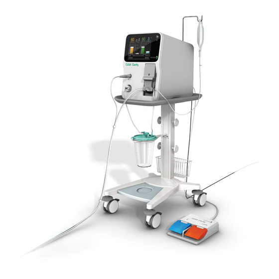
2.2 Console Components and Accessories This section describes the console and optional cart for the CUSA Clarity Ultrasonic Surgical Aspirator System. It describes the major subsystem components and accessories of the console. Console Features The figure illustrates the console on the optional cart. The components are described in the table. ➀... - Page 15 Console – Front Panel The figure illustrates the front view of the console. The components are described in the table. ➀ ➁ ➅ ➂ ➃ ➄ Component Description ➀ Power Button Powers the system on and off. ➁ Handpiece Cable Connector Connects the handpiece to the console.
- Page 16 Console – Rear Panel The figure illustrates the rear view of the console. The components are described in the table. ➀ ➇ ➆ ➁ ➅ ➄ ➃ ➂ Component Description ➀ System Fan Vent Fan keeps internal system cool. ➁ Potential Equalization Terminal For use in locations where Potential Equalization Conductors are used.
-
Page 17: Touchscreen Display And Functions
2.2.1 Touchscreen Display and Functions The Touchscreen layout consists of the Main Screen, Setup Tasks Screen, Settings Screen, and Online Help Screen. Main Screen To access the Main Screen, press the Main Screen button from any other screen. The Main Screen contains ultrasonic control scales for amplitude, Tissue Select® feature, aspiration, and irrigation, slide buttons for the footswitch and aspiration modes, and buttons to open the setup tasks, settings, and online Help screens. -
Page 18: Handpiece Components
2.2.2 Handpiece Components The CUSA® Clarity handpiece is a hand-held surgical device. It houses a transducer that vibrates at an ultrasonic frequency, transferring the vibrations to a hollow titanium tip. When applied to patient tissue, the vibrating tip provides the desired surgical effect – the fragmentation and removal of specific tissue. - Page 19 ➁ ➀ The tip is a hollow titanium tube that touches patient tissue. When active, the tip vibrates at an ultrasonic frequency, causing it to fragment tissue. ➀ The tip has two pre-aspiration holes , one on either side, which help to keep the tip clear and provide better visibility at the surgical site. ➁...
- Page 20 Flue The single-use flue is a translucent silicone tube tapered at one end that provides a sleeve over the tip. Irrigation fluid flows through an irrigation connection tube at one end of the flue and down the tip to the surgical site. The single-use flue is sterile in a single use tip pack and nonsterile in an EUT pack.
- Page 21 Aspiration Tubing • Aspirates away used irrigation fluid, fragmented tissue, and other aspirated materials to the canister • Connects to the aspiration port at the base of the handpiece, passes through the suction pinch valve, and connects to the aspiration port on the canister •...
-
Page 22: Footswitch Component
2.2.3 Footswitch Component The Footswitch controls the level of power to the handpiece from pressure applied to the footswitch. Attaching the Footswitch Align the red dot on the footswitch cable connector with the red dot on the footswitch port on the rear of the console and plug in the footswitch cable. CUSA®... -
Page 23: Chapter 3 Assembling The System Prior To Use
Chapter 3 - Assembling the System Prior to Use 3.1 Overview This section describes how to assemble the console and cart, and to attach the power cord. 3.2 Assembling the Console and Cart 1. Place the console on the cart by aligning the four (4) feet on the bottom of the console with the four (4) indentations on the cart. 2. -
Page 24: Attaching The Power Cord
3. Under the top of the cart, insert and turn counter-clockwise the provided screw. 3.3 Attaching the Power Cord 1. Plug the power cord into the back of the console. 2. Plug the plug end into the wall receptacle. Note Make sure you position the console so that you can quickly access the power cord in case you need to disconnect it. -
Page 25: Chapter 4 System Setup In The Sterile Environment
WARNING Do not use a damaged handpiece with the CUSA Clarity system. This may result in injury to the patient or user. 3. Hold the handpiece in the base and place the torque wrench (color side towards handpiece) over the tip. - Page 26 CAUTION To avoid product damage, always use the torque base to hold the handpiece while using the torque wrench to tighten or loosen the tip. Avoid over torqueing the tip. 4. Rotate the torque wrench clockwise until it clicks twice. Note Keep the torque wrench and base in the sterile field in case you need to change a tip during the procedure and for disassembly after surgery.
- Page 27 3. Slide the flue onto the nosecone base along the tip. 4. Align the flue with the pre-aspiration holes at the distal end of the tip. Note When the pre-aspiration holes are completely covered, most of the irrigation fluid may aspirate back through the handpiece, impairing cavitation; thus reducing tissue ablation efficacy.
- Page 28 2. Assemble the larger loop of the irrigation and aspiration tubing set to the handpiece. 3. Place the cartridge and smaller loop of the irrigation and aspiration tubing set aside until it is time to connect it to the console. 4.
- Page 29 5. Attach the irrigation tubing to the lock fitting on the handpiece flue. Note When the pre-aspiration holes are completely covered, most of the irrigation fluid may aspirate back through the handpiece, impairing cavitation; thus reducing tissue ablation efficacy. 6. Push the irrigation tubing into the clip at the base of the handpiece. Note Do not insert the handpiece cable into the clip at the base of the handpiece.
- Page 30 7. Clip the handpiece cable to the aspiration tubing using clips available along the aspiration tubing. 8. Keep sufficient tubing and cable in the sterile field to allow you to reposition the console. 9. Pass off the cartridge and smaller loop of the irrigation and aspiration tubing set and handpiece cable connector outside of the sterile field. CUSA®...
-
Page 31: Chapter 5 System Setup In The Non-Sterile Environment
Note The purpose of the startup tone verifies that the audio alarms are functioning correctly. If this tone does not sound during the startup process, contact Integra for service. 5.4 Attaching the Footswitch Align the red dot on the footswitch cable connector with the red dot on the footswitch port on the rear of the console and plug in the footswitch cable. -
Page 32: Attaching The Handpiece
5.5 Attaching the Handpiece Pass out the handpiece cable connector from the sterile environment, align the red dot on the handpiece cable connector with the red dot on the handpiece port on the front of the console, and plug in the handpiece cable. 5.6 Connecting the Tubing Set Note Do not insert the handpiece cable into the clip at the base of the handpiece. - Page 33 WARNING To avoid injury to the user, keep fingers away from the peristaltic pump and pinch valve. 3. Close the cartridge door. 4. Connect the contamination guard to the vacuum port of the canister. Make sure the contamination guard is in place and check expiration date. Note Contamination guard must be replaced every six months or when the color changes.
- Page 34 5. Connect the aspiration tubing to the patient port of the canister. Note Make sure the remaining ports on the canister are covered. 6. From the rear of the console, lift the IV pole straight up. CUSA® Clarity System Service and Maintenance Manual Page 34 of 117 0645403-2-EN...
- Page 35 7. Rotate the IV pole hook 180 degrees to the left until you feel it lock into place. 8. Hang the irrigation fluid bag on the IV pole hook. Use saline or Lactated Ringer’s solution. CUSA® Clarity System Service and Maintenance Manual Page 35 of 117 0645403-2-EN...
- Page 36 9. Remove cover from the IV spike end of the irrigation tubing. CUSA® Clarity System Service and Maintenance Manual Page 36 of 117 0645403-2-EN...
-
Page 37: Chapter 6 Cleaning And Sterilizing The System
Operator’s Manual is essential to the longevity and proper operations of the system. This chapter provides the trained technician or engineer the capability to properly clean and sterilize the CUSA Clarity system components and accessories. 6.2 Detaching System Components After a surgical procedure, keep or discard components and accessories based on the following table. - Page 38 3. Remove the aspiration tubing from the aspiration port at the base of the handpiece. 4. Remove the irrigation tubing from the fitting on the handpiece flue. 5. Slide the flue off the nosecone base along the tip. CUSA® Clarity System Service and Maintenance Manual Page 38 of 117 0645403-2-EN...
- Page 39 6. Twist off the nosecone counter-clockwise until it unlocks. 7. Slide the nosecone off the tip. 8. Place the handpiece on the torque base as shown and make sure that the two flat metal sides fit snugly in the metal slot at the end of the base.
- Page 40 10. Rotate the torque wrench counter-clockwise. 11. Unthread the tip from the handpiece connecting body by turning the tip counter-clockwise by hand. 12. Discard the items listed in Table 6-1 in compliance with hospital policy for contaminated waste. Detaching the Console 1.
- Page 41 2. Disconnect the contamination guard tubing from the vacuum port of the canister. NOTE The contamination guard should not be removed from the console unless it is time to replace it (every six months or when the color changes). 3. Open cartridge door, if necessary press the pinch valve button, and remove the cartridge from the console by sliding it up. CUSA®...
- Page 42 4. Detach the handpiece cable from the console by gently pulling on the handpiece cable connector in the handpiece port on the front of the console. 5. Unplug the power cord from the wall receptacle and the console. 6. Disconnect the footswitch cable connector from the back of the console. CUSA®...
-
Page 43: Cleaning And Sterilizing The System
WARNING Electric Shock Hazard - Always unplug the CUSA Clarity System before cleaning or sterilizing it. WARNING Bio-hazardous waste may be present. Do not perform service procedures on the console, handpiece and foot-pedal or its cables or components until all have been decontaminated. -
Page 44: Cleaning Procedures
6.3.1 Cleaning Procedures Cleaning the Touchscreen: Clean the touchscreen with a lint-free wipe and a cleaner. The cleaner may be window/glass cleaner, eyeglass cleaner, or an ammonia-based disinfectant. Always apply the cleaner to the lint-free wipe, never directly on the touchscreen, to avoid scratching the surface. Note Do not wipe the touch screen with a sponge because it may scratch the surface. -
Page 45: Sterilizing The System
6.3.2 Sterilizing the System Sterilize the CUSA® Clarity system components and accessories with steam. Some of the CUSA Clarity system accessories are sterile, single-use items. Other accessories are reusable. Table 6-2 describes the sterilization requirements for the handpiece and accessories. - Page 46 Package the handpiece and components for sterilization. Integra provides a sterilization tray for steam sterilization of the CUSA® Clarity handpiece. This tray protects the handpiece during sterilization and during transfer to the sterile field. Packaging the Handpiece and Components for Sterilization The handpiece and components must be cleaned prior to sterilization, see “Cleaning the Handpiece, EUT, and Torque Base”...
- Page 47 EUT Sterilization Tray Configuration ➀ 1. Place the handpiece in the appropriate slot and align it with the outline on the bottom of the tray. ➁ 2. Wrap the handpiece cable around the posts ➂ 3. Place the handpiece connector in the appropriate slot and align it with the outline on the bottom of the tray.
- Page 48 Sterilizing the Handpiece and Components with Steam Sterilizing the handpiece with steam depends on the following factors: • Temperature • Exposure time • Population and resistance of resident bioburden • Method of air removal from the autoclave Use the validated steam sterilization cycle parameters outlined in these instructions. If you deviate from this recommended method of sterilizing, it is your Health Care Facility’s responsibility to validate the deviation.
-
Page 49: Chapter 7 Maintenance And Functional Testing
This Preventive Maintenance is to ensure that Essential Performance of the CUSA Clarity system remains valid for the stated service life of the product and to guarantee safe operation for the patient and the user. - Page 50 Handling and Transportation of the System If you need to move/relocate the CUSA Clarity Ultrasonic Surgical Aspirator System within the environment of the Healthcare Facility, note the guidelines below: Before moving the console: • Power off the system. • Unplug the power cord from the wall receptacle and secure it. •...
-
Page 51: Disposal Of The Equipment
Footswitch You do not need to disconnect the footswitch from the console except for maintenance or service. When you are not using CUSA Clarity System, secure the footswitch cord. 7.4 Disposal of the Equipment The CUSA Clarity Ultrasonic Surgical Aspirator System console, handpiece, and footswitch are considered electrical equipment and must be disposed of in accordance with regional regulation hospital protocols. -
Page 52: Periodic Maintenance Schedule
• Serial number (located on the CUSA Clarity console rear panel) 7.6 Periodic Maintenance Schedule The CUSA Clarity system is designed to meet the requirements specified in IEC 62353, Edition 2.0 2014-9. Record all periodic maintenance activities on the data sheet supplied with this manual. - Page 53 7.7 Visual Inspection The CUSA Clarity console, handpiece, and all associated components and accessories should be visually inspected for various forms of disrepair prior to disassembling, cleaning, sterilizing, or proceeding with preventive maintenance. Replace all damaged components and accessories. When conducting a visual inspection, the technician shall: •...
-
Page 54: Electrical Safety Tests
7.8 Electrical Safety Tests The electrical safety tests are required to meet the requirements specified in IEC 62353, Edition 2.0 2014-9. Refer to Integra Global Service and Repair Procedure IT0738 for instructions to complete the tests. This Integra Global Service and Repair Procedure IT0738 and test datasheet are located in Appendix A. -
Page 55: Test Conditions
7.8.2 Test Conditions Perform the electrical safety test at the ambient temperature, humidity, and atmospheric pressure at the testing site. 7.8.3 Normalization Instructions As this test is performed with mains voltage present at the site of testing, measurements have to be normalized before comparing with acceptance criteria. - Page 56 3. Measure the Protective Earth Resistance for each connection listed below: Test Description Unit Acceptance Criteria Equipotential Earth Ground pin Ω ≤ 300 mΩ Cartridge Door Ω ≤ 300 mΩ Handpiece Socket Connector Ω ≤ 300 mΩ Table 7-4 Protective Earth Resistance Acceptance Criteria 4.
- Page 57 WARNING When measuring equipment leakage current of Class I ME equipment, an interruption of the grounding connection endangers system technicians and bystanders. NOTE The Direct Method delivers erroneous values when supplied by an IT power system. (b) IT-System (Alternative Method) 1.
- Page 58 Measurements of Applied Part Leakage Current (a) TN-System (Direct Method AC) 1. The Safety Analyzer is connected directly to the mains on TN-System 2. Connect the console to the main power socket of the Safety Analyzer. Figure 7-4 3. Select Applied Part Leakage Current measurement on the safety Analyzer. 4.
-
Page 59: Electrical Safety Test Record Assessment
7.9 Functional Tests 7.9.1 Test Conditions Refer to Integra Global Service and Repair Procedure IT0739 for instructions to complete the tests. This Integra Global Service and Repair Procedure IT0739 and Test Datasheet are located in Appendix A CUSA® Clarity System Service and Maintenance Manual... -
Page 60: Required Equipment And Tools
Equipment/Tools Description Digital Manometer Fisher 3461 or Fluke PV350 or Equivalent CUSA Clarity 36 kHz Handpiece Integra Ref. C7036 CUSA Clarity 36 kHz tip Integra Ref. C7414 Handheld digital tachometer Testo 470 or DT2236 or equivalent Reflective tape for the digital tachometer... -
Page 61: Returning The Clarity System To Use
• Record aspiration values in IT0739A CUSA Clarity GS&R End User Functional Test Datasheet 7.10 Returning the Clarity System to Use When functional testing is complete, accomplish the following actions to return the CUSA Clarity system to service: • Clean the system •... - Page 62 Intentionally Blank CUSA® Clarity System Service and Maintenance Manual Page 62 of 117 0645403-2-EN...
-
Page 63: Chapter 8 Troubleshooting The System
Console Failure A fault condition has been detected within the console Restart console, contact Integra Service if problem persists No fragmentation No fragmentation may occur while using CUSA Clarity in • Go into Stand-by conjunction with a monopolar eletrosurgery system •... -
Page 64: Technical Messages
Recommendation Fan Failure Contact Integra Service Low battery System is useable, but notify Integra Service No Fragmentation No fragmentation may occur while using CUSA Clarity in conjunction with a monopolar eletrosurgery system. If you experience no fragmentation, take the followings steps: •... -
Page 65: General Troubleshooting
8.5 General Troubleshooting Troubleshooting Call Integra for Does the assistance. Call Integra for Is a critical part screen light up assistance. damaged? Setup the console with main power cord, known working handpiece, tubing Call Integra for set and footswitch. Does the touch assistance. -
Page 66: Amplitude Troubleshooting
• Press the pinch valve button to open and close the valve 3 to 5 times to ensure the valve closes completely • Replace cartridge set • Contact Integra Service Difficulty with removing cartridge • If the system is powered on, lift the cartridge door and remove cartridge •... -
Page 67: Irrigation Troubleshooting
- If set to «On Demand » the pinch valve should be Replace the suction open only when you activate Ultrasonics. Suction canister full? canister. If these conditions do not exist, call Integra for assistance. Figure 8-2 8.8 Irrigation Troubleshooting Condition... - Page 68 Irrigation pump - If set to «On Demand » the Irrigation pump not turning? should be turning only when you activate Ultrasonics. If these conditions do not exist, call Integra for Remove the pinch assistance. Irrigation tubing or kink from the pinched or kinked? tubing.
-
Page 69: Status Bar Root Causes And Solutions
Perform Setup Task: - If the footswitch is already connected, replace the Connect footswitch footswitch (part number C7002). - if the problem persists, call Integra for assistance. System is overheating. Contact - Call Integra for assistance. - Check if the handpiece connector is properly service connected. -
Page 70: Error Code Matrix
8.10 Error Code Matrix For all error codes, except those explained below, contact Integra Service and Repair for assistance.. Error Code Description Root Cause Solution 1 Solution 2 E1208 Vacuum Pressure Low Vacuum is lower than expected Connect a contamination... - Page 71 - If set to «On Demand » the pinch valve should be tube. open only when you activate Ultrasonics. If these conditions do not exist, call Integra for assistance. - Examine the Aspiration line along its A blockage in the entire length for a blockage.
- Page 72 If the test fail press Detail button and follow instructions. (Refer to Cusa Clarity Operator Manual) - Replace handpiece if problem persists Amplitude level fluctuating on the Call Integra for assistance screen? Figure 8-6 CUSA® Clarity System Service and Maintenance Manual Page 72 of 117 0645403-2-EN...
-
Page 73: Chapter 9 Disassembly And Reassembly Of Sub-Assemblies
WARNING Turn off the power before opening the console - disconnect the power cord. CAUTION Only authorized engineer by Integra can open the console NOTE Discard lock washers removed during disassembly and replace with new lock washers when reassembling. NOTE When reassembling a lock washer and a flat washer, always place the lock washer between the screw head and the flat washer. -
Page 74: Pole Replacement Ref. S30905284
9.3 IV Pole Replacement Ref. S30905284 Removal Unscrew the 2 x M5 x 35 Ref. 72904930 screws as shown in Figure 9-1 using 3 mm Allen bit. The IV pole will come apart. Unscrew Figure 9-1 Installation Position the IV pole as shown in Figure 9 2; refit the 2 x M5 x 35 Ref. 72904930 screws using 3 mm Allen bit. Ensure the IV pole is sliding up and down. -
Page 75: Disassembling Cusa® Clarity Console From Cart
9.4 Disassembling CUSA® Clarity Console from Cart Under the top of the cart, remove the M8 X 60 MM SOCKET HEAD CAP SCREW Ref. S72905320 and M8 EXTERNAL TOOTH LOCK WASHER Ref. S72905321 using HEX L-KEY, 6 MM Ref. S72905103 provided with the Cart as shown in Figure 9 3. CAUTION The CUSA Clarity console weight is 29.5 kg (65 lbs). -
Page 76: Assembling Cusa Clarity Console On Cart
9.5 Assembling CUSA Clarity Console on Cart Place the console on the cart by aligning the four (4) feet on the bottom of the console with the four (4) indentations on the cart as shown in Figure 9 5. CAUTION The CUSA Clarity console weight is 29.5 kg (65 lbs). -
Page 77: Cart Base Plate Replacement Ref. S72905007
Screw Figure 9-6 9.6 Cart Base Plate Replacement Ref. S72905007 Removal Remove CUSA Clarity Console from the Cart according to Section 9.4 Disassembling CUSA Clarity Console from Cart. • Remove the 4 x SCREW, SOCKET HEAD CAP, M8x50 MM Ref. S72905358 and the WASHER, EXTERNAL TOOTH, M8 Ref. S72905359 as shown in Figure 9-7. -
Page 78: Cart Vacuum Canister Holder Replacement Ref. S72905009
Installation Refit the 4 x SCREW, SOCKET HEAD CAP, M8x50 MM Ref. S72905358 and the WASHER, EXTERNAL TOOTH, M8 Ref. S72905359 as shown in Figure 9-8. Screw Lock Washer Figure 9-8 Reinstall CUSA Clarity Console on the Cart according to section 9-5 Assembling CUSA Clarity Console on Cart. NOTE Cart Base Plate Replacement (Ref. - Page 79 Installation Align VACCUM CANISTER HOLDER Ref. S72905009 holes with the 2 x SPRING NUT, M6 Ref. S72905363, as shown in Figure 9-10 M6 Nut Figure 9-10 Refit the 2 x SCREW, FLAT-HEAD SOCKET CAP, M6X12 MM Ref. S72905360 and the WASHER, EXTERNAL TOOTH, M6 Ref. S72905361 as shown in Figure 9-11.
-
Page 80: Cart Foot Switch Basket Replacement Ref. S72905053
9.8 Cart Foot Switch Basket Replacement Ref. S72905053 Removal Unscrew and remove the 3 x SCREW, BUTTON HEAD CAP, M6X10 MM Ref. S72905364, the SCREW, BUTTON HEAD CAP, M6X12 MM Ref. S72905365 and the SERRATED WASHER Ref. S72905368 as shown in Figure 9-13. Unscrew Figure 9-13 Installation... -
Page 81: Cart Cable Winding Peg Replacement Ref. S72905054
Refit the 3 x SCREW, BUTTON HEAD CAP, M6X10 MM Ref. S72905364, the SCREW, BUTTON HEAD CAP, M6X12 MM Ref. S72905365 and the WASHER, LOCK, M6 Ref. S72905368 as shown in Figure 9 15. Screw MKX12 Lock Washer Figure 9-15 NOTE Cart Foot Switch Basket Replacement (Ref. -
Page 82: Cart Caster Replacement Ref. S72905055
Installation Align the Cart Cable Winding Peg Ref. S72905054 holes with the M6 SPRING NUT Ref. S72905363, as shown in Figure 9-17. Figure 9-17 Refit the SCREW, SOCKET HEAD CAP, M6X12 MM Ref. S72905369 as shown in Figure 9-17. Refit the COVER, WINDING PEG, CART, PHOENIX Ref. S72905366 as shown in Figure 9-17. NOTE Cable Winding Peg Replacement (Ref. -
Page 83: Cart Caster Bumper Replacement Ref. S72905056
Installation Engage the M12 FLAT WASHER Ref S72905383 on the Caster shaft. With 21 mm spanner, refit the Caster Ref. S72905055 as shown in Figure 9-18. 9.11 Cart Caster Bumper Replacement Ref. S72905056 Removal Remove CUSA Clarity Console from the Cart according to section 9-4 Disassembling CUSA Clarity Console from Cart. •... - Page 84 • Unscrew and remove the 4 x SCREW, SHEET METAL, 6.3 X 16 MM Ref. S72905371 and the 2 x WASHER, M6 Ref. S72905393 as shown in the Figure 9-20. Unscrew Figure 9-20 • Take out the Cart Weight Cover Ref. S72905051 as shown in Figure 9-21. Figure 9-21 Installation Refit the Cart Weigh Cover Ref.
- Page 85 Figure 9-22 Refit the 4 x SCREW, SHEET METAL, 6.3X16 MM Ref. S72905371 and the 2 x WASHER, M6 Ref. S72905393 as shown in the Figure 9-23. Place MAX LOAD LABEL Ref. S72905370 on the Cart Weigh Cover as shown in Figure 9-22. Screw Figure 9-23 CUSA®...
- Page 86 Intentionally Blank CUSA® Clarity System Service and Maintenance Manual Page 86 of 117 0645403-2-EN...
-
Page 87: Chapter 10 Technical Specifications
Chapter 10 - Technical Specifications 10.1 Console 10.2 Dimensions CUSA® Clarity Console without Cart Height 49.3 cm (19.5 in) Width 34.9 cm (13.75 in) Depth 45.7 cm (18 in) Weight 29.5 kg (65 lbs) Cable Length 5 m (196.85 in) CUSA Clarity Console with Cart Height 1.33 m (52.5 in) -
Page 88: Tip Specifications
10.3 Tip Specifications Inside Amplitude Outside Length imension Dimension (peak to peak) Weight (g) (mm) [in] (mm) [in] (mm) [in] (µm) [in] Curved Extended 160 to 206 121.5 [4.783] 1.6 [0.062] 2.0 [0.077] MicroTip [0.0063 to 0.0081] Curved Extended 127 to 163 1.6 [0.062] 2.0 [0.077] 192.7 [7.588... -
Page 89: Handpiece
10.5 Handpiece Dimensions Length 13.03 cm (5.13 in) Diameter 2.41 cm (0.95 in) Weight 71 g (0.15 lb) Cable Length 463.3 cm (182.4 in) Frequency High 36 kHz 10.6 Electrical Requirements 10.6.1 Power Input and Fusing Voltage 100-240V~ Frequency 50-60Hz Power 480VA Phases... -
Page 90: Maximum Low Frequency Leakage
Only use Integra approved power cords. WARNING Explosion Hazard - Do not use the CUSA Clarity System in the presence of flammable anesthetics or other volatile solvents. WARNING To avoid risk of electric shock, this equipment must only be connected to a supply mains with protective earth. -
Page 91: Environment
Other devices in the operating room may generate electromagnetic interference. Use caution in locating equipment within the room to reduce the electromagnetic interference. 10.9 Voluntary Standards The CUSA Clarity system meets the following standards: • IEC 60601-1:2005 +CORR. 1:2006 + CORR.2:2007 + AM1:2012 Medical Electrical Equipment Part 1: General Requirements for Basic Safety and Essential Performance, Third Edition Amendment 1 •... -
Page 92: Guidance And Manufacturer's Declarations
Note The CUSA Clarity system should not be used adjacent to or stacked with equipment other than the equipment specified in the CUSA Clarity Ultrasonic Surgical Aspirator System Operator’s Manual. If adjacent or stacked use is necessary, the CUSA Clarity system should be observed to verify normal operation in the configuration in which it will be used. - Page 93 Guidance and Manufacturer’s Declaration – Electromagnetic Immunity The CUSA Clarity system is intended for use in the electromagnetic environment specified below. The customer or the user of the CUSA Clarity system should assure that it is used in such an environment. IEC 60601-1-2...
- Page 94 Guidance and Manufacturer’s Declaration – Electromagnetic Immunity The CUSA Clarity system is intended for use in the electromagnetic environment specified below. The customer or the user of the CUSA Clarity system should assure that it is used in such an environment. Electromagnetic Environment...
- Page 95 TV broadcast cannot be predicted theoretically with accuracy. To assess the electromagnetic environment due to fixed RF transmitters, an electromagnetic site survey should be considered. If the measured field strength in the location in which the CUSA Clarity system is used exceeds the applicable RF compliance level above, the CUSA Clarity system should be observed to verify normal operation.
-
Page 96: Chapter 11 Replacement Parts
Ratingen 40880 Germany Tel: +49 2102 5535 6150 Fax: +49 2102 942 4872 E-mail: emea.techservice@integralife.com Asia Pacific Service Center Integra NeuroSciences Pty. Ltd. Unit 3, 24-30 Winterton Road CLAYTON, VIC. 3168, Australia Tel: +613 85400400 Fax: +613 95400004 E-mail: service@integralife.com.au 11.2 Field Replacement Part list... - Page 97 Item Part from Part Status Description Unit Qty/Unit S72905320 CUSA® Clarity Cart Field Replacement Part SOCKET HEAD CAP SCREW, M8x60 Each S72905321 CUSA® Clarity Cart Field Replacement Part M8 EXTERNAL TOOTH LOCK WASHER Each S72905358 CUSA® Clarity Cart Field Replacement Part SCREW, SOCKET HEAD CAP, M8x50 MM Each S72905359...
- Page 98 Intentionally Blank CUSA® Clarity System Service and Maintenance Manual Page 98 of 117 0645403-2-EN...
-
Page 99: Chapter 12 Warranty
Integra® CUSA® Clarity Ultrasonic Surgical Aspirator System (“CUSA® Clarity”) is free from defects in materials and workmanship under normal use and service for a period of one (1) year from the date of delivery (“Warranty Period”) by Integra to the original purchaser, but in no event beyond the expiration date stated on any product labeling (hereinafter the Warranty Period). -
Page 100: Repair Parts And Services
Consoles. Integra or its distributor, when authorized for this purpose, shall, if possible, perform on-site repair of consoles and where not possible or otherwise decided at the sole discretion of Integra, Integra or its distributor shall arrange and pay to ship the affected Equipment to the designated repair facility. -
Page 101: Limitation Of Liability
OTHERWISE, OR APPLIACTION OR WARRANTY OF QUALITY AS WELL AS ANY EXPRESS OR IMPLIED WARRANTY TO PATIENTS. Further, this warranty shall not apply to, and Integra shall not be responsible for, any loss arising in connection with the purchase or use of any Integra product that has been repaired by anyone other than an authorized Integra service representative or altered in any way so as, in Integra’s sole judgment,... -
Page 102: Appendix A: Integra Global Service & Repair Test Procedures (It0738 & It0739) And Test Data Sheets
Appendix A: Integra Global Service & Repair Test Procedures (IT0738 & IT0739) and Test Data Sheets Test Procedure IT0738 CUSA®Clarity GS&R Safety Test Procedure Issued: 19 Jan 2017 1.0 Purpose This procedure provides a method to conduct CUSA® Clarity Safety test according IEC 62353. - Page 103 Note This instruction of test is developed to be conduct with Rigel 288 Safety Analyzer. Using another Safety Analyzer model may require some adaptations. Prerequisites Before performing this protocol, record the serial number, calibration due date for all calibrated equipment and other required data in the test datasheet IT0738A.
- Page 104 In this condition, EQUIPMENT LEAKAGE CURRENT and APPLIED PART LEAKAGE CURRENT must be done with Alternative method. 9.0 Measurements of Mains Voltage • With the DMM, measure the mains voltage between phase and neutral lines as well as frequency. • Record the values in IT0738A. 10.0 Measurements of Protective Earth Resistance •...
- Page 105 • From the Rigel 288 main menu, select Manual Mode –> IEC62353 –> Equipment Leakage Test –> Direct as shown below: • Press Button and set the Test Duration to (time) unlimited. Press Button to exit Settings mode without saving changes. •...
- Page 106 12.0 Measurements of Applied Part Leakage Current 12.1 TN-System (Direct method) • The Safety Analyzer is connected directly to the mains (TN-System only). • The DUT (Device Under Test) mains lead is connected to mains socket on the Rigel 288. •...
-
Page 107: Revision History
12.2 IT-System (Alternative method) • The Safety Analyzer is connected directly to the mains (IT-System only). • The DUT (Device Under Test) mains lead is connected to mains socket on the Rigel 288. • Connect the handpiece and the footswitch. •... - Page 108 Serial Number / Calibration Due ID Number Date Footswitch Integra Ref. C7002 CUSA® Clarity 36 kHz Handpiece Integra Ref. C7036 CUSA® Clarity 36 kHz Curved Ext MicroTip (Single Pack) Integra Ref. C7414 CUSA® Clarity Quick Connect Tubing Set (Single Pack) Integra Ref.
- Page 109 CUSA® Clarity System Service and Repair Work Instruction 5.0 Equipment Equipment Description CUSA® Clarity console system (DUT) Integra Ref. C7000 Footswitch Integra Ref. C7002 CUSA® Clarity 36 kHz Handpiece Integra Ref. C7036 CUSA® Clarity 36 kHz Curved Ext MicroTip(Single Pack) Integra Ref.
-
Page 110: Test Setup
6.0 Test conditions The tests may be performed at the ambient temperature, humidity, atmospheric pressure and mains voltage as present at the site of testing. 7.0 Visual inspection Visually inspect the console for signs of damage which would affect the normal operation and function of the system. Check the following items: 1. - Page 111 • Place the cartridge on the pump head, close the door and connect the aspiration tubing set to the canister. • Attach the T connector in line between the distal end of the aspiration tubing set and the handpiece suction port. •...
- Page 112 Equipment Equipment Type Serial Number / Calibration Due ID Number Date CUSA® Clarity 36 kHz Integra Ref. C7036 CUSA® Clarity 36 kHz Curved Curved Ext MicroTip Integra Ref. C7414 (Single Pack) Handheld digital tachometer Testo 470 Digital Manometer Fisher 3461 or Fluke PV350 or Equivalent...
- Page 113 Ultrasound Test Result Expected value Pass Fail Tip Frequency Optimization Amplitude Test > 50% Irrigation Test Result Expected value Pass Fail Select Irrigation at 2 ml/min 2 to 8 RPM Press fast flush pedal 34 to 47 RPM Aspiration Test Result Expected value Pass...
- Page 114 Intentionally Blank CUSA® Clarity System Service and Maintenance Manual Page 114 of 117 0645403-2-EN...
-
Page 115: Appendix B: Serial Number Nomenclature
Appendix B: Serial Number Nomenclature Use the serial number to determine the manufacture date and age of the console. All CUSA® Clarity Systems have a 12-digit serial number. The descriptions and meanings of serial number digits is below. Serial Number Format (12 Digits) Product Group Group Identifier... - Page 116 Month of Manufacture F: June Year of Manufacture 16: 2016 Unit Number 001: 001 (First unit built in June) Modification State 01: 01 Manufacturing Plant IE: Integra LifeSciences, Ireland CUSA® Clarity System Service and Maintenance Manual Page 116 of 117 0645403-2-EN...
- Page 117 Manufacturer Integra LifeSciences (Ireland) Limited IDA Business &Technology Park Sragh Tullamore County Offaly Ireland USA & Canada: (800) 997-4868 Outside USA: (609) 936-5400 www.integralife.com CUSA® Clarity System Service and Maintenance Manual Page 117 of 117 0645403-2-EN...
Need help?
Do you have a question about the CUSA Clarity System and is the answer not in the manual?
Questions and answers