Integra CUSA Clarity Operator's Manual
Ultrasonic surgical aspirator system
Hide thumbs
Also See for CUSA Clarity:
- Service and maintenance manual (117 pages) ,
- Instructions for use manual (84 pages) ,
- Cleaning instruction manual (12 pages)
Table of Contents
Advertisement
Quick Links
Manufacturer
Integra LifeSciences (Ireland) Limited
IDA Business &Technology Park
Sragh
Tullamore
County Offaly
Ireland
USA & Canada: (800) 997-4868
Outside USA: (609) 936-5400
www.integralife.com
60905197 Revision F 05/18 0606553-2
Operator's Manual
Integra
CUSA
Clarity
®
®
Ultrasonic Surgical Aspirator System
Advertisement
Table of Contents
Troubleshooting

Related Manuals for Integra CUSA Clarity


Summary of Contents for Integra CUSA Clarity
- Page 1 Operator’s Manual Integra CUSA Clarity ® ® Ultrasonic Surgical Aspirator System Manufacturer Integra LifeSciences (Ireland) Limited IDA Business &Technology Park Sragh Tullamore County Offaly Ireland USA & Canada: (800) 997-4868 Outside USA: (609) 936-5400 www.integralife.com 60905197 Revision F 05/18 0606553-2...
- Page 2 CUSA Clarity ® Ultrasonic Surgical Aspirator System Operator’s Manual...
-
Page 4: Table Of Contents
Table of Contents Table of Contents PREFACE Intended Audience ........................ix Trademark Acknowledgments ....................ix Manufacturer ..........................x Patent Information ........................x Overview of Manual ........................x System Features......................... xi Intended Uses..........................xi Conventions Used in this Guide ....................xi SECTION 1 Patient and Operating Room Safety Indications for Use ........................ - Page 5 Table of Contents SECTION 4 Touchscreen Display and Functions Overview..........................4-1 Touchscreen Layout......................... 4-1 Main Screen ........................4-2 Setup Tasks Screen ......................4-3 Settings Screen ........................4-3 Online Help......................... 4-4 Alarm Indicators ........................4-4 Ultrasonic Control Scale Adjustments ..................4-5 Adjusting the Ultrasonic Control Scale Values ..............
- Page 6 Table of Contents SECTION 8 System Setup in the Non-Sterile Field Overview..........................8-1 Quick Reference: Setting Up in the Non-Sterile Field ............... 8-1 Assembling the Handpiece ...................... 8-2 Console Setup (Non-Sterile) ....................8-2 Powering Up the System ....................8-2 Attaching the Footswitch ....................8-3 Attaching the Handpiece ....................
- Page 7 Returning the Console ...................... 12-5 Returning the Handpiece ....................12-5 Ordering Replacement Parts .................... 12-5 Integra Service Centers ......................12-6 US Service Center ......................12-6 Europe, Middle East and Africa Service Center ..............12-6 Asia Pacific Service Center ....................12-6 SECTION 13 Troubleshooting the System Overview..........................
- Page 8 Table of Contents SECTION 14 MR Safety Information Overview..........................14-1 Use of the CUSA Clarity System in the MR environment ............14-2 SECTION A Technical Specifications Console ........................... A-1 Dimensions ........................A-1 Tip Specifications ........................A-2 Subsystems ..........................A-3 Handpiece ..........................A-3 Dimensions ........................
- Page 9 Table of Contents Intentional Blank viii CUSA Clarity Ultrasonic Surgical Aspirator System Operator’s Manual ®...
-
Page 10: Preface
Federal (USA) law restricts this device to sale by or on the order of a physician. Trademark Acknowledgments Integra, the Integra logo, CUSA, and Tissue Select are registered trademarks of Integra LifeSciences Corporation or its subsidiaries in the United States and/or other countries. ShearTip, MicroTip, and CUSA Quick Connect are trademarks of Integra LifeSciences Corporation or its subsidiaries. -
Page 11: Manufacturer
D819,195; additional patent(s) pending Overview of Manual This operator’s manual describes how to use the CUSA Clarity Ultrasonic Surgical Aspirator System. It presents the CUSA Clarity as a system that includes a console, handpieces, and accessories. It describes: • The system and its functions •... -
Page 12: System Features
® tip, allowing greater control and precision Intended Uses of this Manual When you receive your CUSA Clarity system, we recommend that you read and understand all of this operator’s manual before using the system. Also, use the manual for: •... - Page 13 Preface Intentional Blank CUSA Clarity Ultrasonic Surgical Aspirator System Operator’s Manual ®...
-
Page 14: Section 1 Patient And Operating Room Safety
® surgical procedures where fragmentation, emulsification and aspiration of soft tissue is desirable. The CUSA Clarity Ultrasonic Surgical Aspirator is indicated for use in: • Neurosurgery, Plastic and Reconstructive surgery, Orthopedic Surgery, Gynecological Surgery and Thoracic Surgery and the following specific uses: •... -
Page 15: Intended Users
WARNING It is the responsibility of the Healthcare Facility to ensure that intended users of the CUSA Clarity system are appropriately trained in the use of this equipment. Safety Information The safe and effective use of ultrasonic surgery depends to a large degree on factors solely under the control of the operator. -
Page 16: Warnings And Cautions
Warnings and Cautions Warnings and Cautions To promote the safe use of the CUSA Clarity system, this section lists the warnings and cautions that appear throughout this operator’s manual. To operate this equipment with maximum safety, it is important to read, understand, and follow the instructions in these warning and cautions. - Page 17 Warnings and Cautions WARNING When the handpiece is connected to a CUSA Clarity system that is powered on, but the handpiece is not in use, keep the handpiece away from the patient. Place the handpiece on a sterile, flat, dry, nonconductive, and highly visible surface.
- Page 18 WARNING Excessive loading of CUSA Clarity tips at the surgical site may induce heating due to vibration and acoustic power transmissions. Thermal management of the surgical site with the aid of the appropriate irrigation and aspiration settings is essential.
- Page 19 Warnings and Cautions WARNING Explosion Hazard - Do not use the CUSA Clarity system in the presence of flammable anesthetics or other volatile solvents. WARNING Electric Shock Hazard - Always unplug the CUSA Clarity system before cleaning it. WARNING Electrical Shock Hazard - Do not remove cover. Refer servicing to authorized service personnel.
- Page 20 To ensure sterility, assemble sterile handpiece and tip in the sterile field only. CAUTION Read the instructions, warnings, cautions, and notes provided with the CUSA Clarity system before use; otherwise, injury to the patient and/or user, or equipment damage may result. CAUTION During surgery, under maximum loading conditions, CUSA Clarity system has an ultrasonic duty cycle of 10 minutes on, 5 minutes off.
- Page 21 CUSA Clarity system, contact between the activated monopolar electrosurgery instrument and the CUSA Clarity surgical tip could affect system functionality. Avoid contact between the CUSA Clarity surgical tip and an activated monopolar surgical instrument.
-
Page 22: Classification And Console Symbols
Classification and Console Symbols Classification and Console Symbols Symbol Description Follow Instructions for Use MR Unsafe This equipment meets type Cardiac Floating (CF) safety standards High Voltage Warning Ground Stud Marking System Power On/Off Handpiece Connector Footswitch Connector Catalogue Number Serial Number Date of Manufacture Manufacturer... - Page 23 Classification and Console Symbols Non-pyrogenic Do not re-use Sterilized using ethylene oxide Do not resterilize Do not use if package is damaged Temperature limitations Humidity limitations This product is not manufactured with Dry Rubber or Natural Rubber Latex Lot number Expiration date Keep dry Non-sterile...
-
Page 24: Overview
Clarity system before use. Otherwise, injury to the patient or ® user or equipment damage may result. This section provides general information about the CUSA Clarity Ultrasonic Surgical Aspirator System: what it is, what it does, and how it works. It also describes the handpiece functions, configurations, and the... -
Page 25: Cusa ® Clarity System
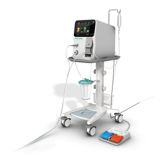
CUSA Clarity System CUSA Clarity System The CUSA Clarity system is an ultrasonic surgical aspirator system that allows a surgeon to remove tissue efficiently and selectively. It performs three functions: • Fragmentation: When the vibrating tip of the handpiece comes into contact with the tissue, the cells of the tissue break apart or “fragment”. - Page 26 CUSA Clarity System The system includes the following items: Components: • Console: houses electronics, pumps, and mechanical parts. It includes a touch screen that allows you to control the functions of the system. • Cart: provides a secure platform for the console. It has a handle and locking casters to facilitate movement and provide storage for the footswitch and power cord.
-
Page 27: Fragmentation
CUSA Clarity System • Accessories: • CUSA Quick Connect Cartridge and Tubing Set: the sterile ™ tubing and cartridge kit includes the aspiration tubing (aspirates away used irrigation fluid, fragmented tissue, and other materials to the canister), irrigation tubing (provides irrigation to the surgical site during the surgical procedure), and a cartridge (connects the tubing to the console). -
Page 28: Aspiration (Suction)
CUSA Clarity System The pump: • Moves fluid at 2 to 20 mL/min; default flow is 3 mL/min. Use the adjustment slider (move the slider up/down on the Irrigation column on the touch screen) to increase or decrease the irrigation flow in 1 mL/min increments. -
Page 29: Touchscreen Display
“Touchscreen Display and Functions” on page 4-1. Handpiece The CUSA Clarity handpiece is a hand-held surgical device. It houses a transducer that vibrates at an ultrasonic frequency, transferring the vibrations to a hollow titanium tip. -
Page 30: Handpiece Configurations
Tissue Select Feature Handpiece Configurations The CUSA Clarity system includes a high frequency handpiece. NOTE The high frequency handpiece operates within a frequency range and 36 kHz is a representative value. See the “Technical Specifications” on page A-3 for the frequency range. - Page 31 Continued manual pressure on the footswitch pedals could result in unintentional damage to critical structures. Using the Tissue Select feature, the CUSA Clarity system can help the surgeon avoid these problems when dissecting near critical structures. Increasing Tissue Selectivity It is possible to increase the inherent selectivity resulting from variations in tissue strength while maintaining amplitude, tip acceleration, and suction.
- Page 32 Tissue Select Feature electrical power (which is directly related to the acoustic power present at the tip, which results in fragmentation) to the handpiece. Consider the power delivered to the handpiece in three terms: • Initial power: the quantity of power necessary to drive the tip vibration in air;...
- Page 33 Tissue Select Feature Tissue Select Settings Ultrasonic energy is inherently selective. It fragments soft tissue more easily than collagen-rich tissue. The Tissue Select feature is a safety setting unique to the CUSA systems that allows the surgeon to increase selectivity and safety without sacrificing procedure speed. The Tissue Select feature limits power when the tip encounters a blood vessel, providing a wider margin of safety in preserving the vessel.
-
Page 34: Sterilization Of Handpieces And Accessories
Sterilization of Handpieces and Accessories Sterilization of Handpieces and Accessories You must sterilize the CUSA Clarity handpiece with steam before use. Some of the CUSA Clarity system accessories are sterile, single-use items. Other accessories are reusable. You must sterilize all reusable accessories with steam before use. - Page 35 Sterilization of Handpieces and Accessories Intentional Blank 2-12 CUSA Clarity Ultrasonic Surgical Aspirator System Operator’s Manual ®...
-
Page 36: Overview
SECTION 3 Console Components In this section: • Overview, page 3-1 • Console Features, page 3-2 • Console – Front Panel, page 3-4 • Console – Rear Panel, page 3-5 Overview This section describes the console for the CUSA Clarity Ultrasonic ®... -
Page 37: Console Features
Console Features Console Features The figure illustrates the console on the optional cart. The components are described in the table. ➀ ➁ ➂ ➃ ➄ ➅ CUSA Clarity Ultrasonic Surgical Aspirator System Operator’s Manual ®... - Page 38 Console Features Component Description Houses the electronics, pumps, and mechanical parts. Console Body It includes a touchscreen that ➀ allows you to control the functions of the system. Connector to plug in the Handpiece Connector ➁ surgical handpiece. The filter and tubing that connects between the canister and the console.
-
Page 39: Console - Front Panel
Console – Front Panel Console – Front Panel The figure illustrates the front view of the console. The components are described in the table. ➀ ➁ ➅ ➂ ➃ ➄ Component Description Power Button Powers the system on and off. ➀... -
Page 40: Console - Rear Panel
Console – Rear Panel Console – Rear Panel The figure illustrates the rear view of the console. The components are described in the table. ➀ ➇ ➆ ➁ ➅ ➄ ➃ ➂ Component Description System Fan Vent Fan keeps internal system cool. ➀... - Page 41 Console – Rear Panel Intentional Blank CUSA Clarity Ultrasonic Surgical Aspirator System Operator’s Manual ®...
-
Page 42: Overview
SECTION 4 Touchscreen Display and Functions In this section: • Overview, page 4-1 • Touchscreen Layout, page 4-1 • Alarm Indicators, page 4-4 • Ultrasonic Control Scale Adjustments, page 4-5 • Footswitch and Aspiration Modes, page 4-6 Overview This section describes the touchscreen display (or “touchscreen”) layout and the behavior during system startup and operation of the CUSA ®... -
Page 43: Main Screen
Touchscreen Layout Main Screen To access the Main Screen, press the Main Screen button from any other screen. The Main Screen contains ultrasonic control scales for amplitude, Tissue Select , aspiration, and irrigation, slide buttons for the footswitch and ® aspiration modes, and buttons to open the setup tasks, settings, and online Help screens. -
Page 44: Setup Tasks Screen
Touchscreen Layout Setup Tasks Screen To access the Setup Tasks screen, press the Setup/Standby button on the Main Screen. The Setup Tasks screen is displayed when the system is powered on. The Setup Tasks screen contains the setup tasks for the footswitch, handpiece, and cartridge, for priming the system, and for testing the handpiece. -
Page 45: Online Help
Refer to the Alarm Descriptions section on 13-2 for information on how to clear alarms. It is recommended that when the CUSA Clarity System is set up for surgery, make sure that the touchscreen is clearly visible to the surgeon in the event of an alarm. -
Page 46: Ultrasonic Control Scale Adjustments
Ultrasonic Control Scale Adjustments Ultrasonic Control Scale Adjustments ➁ ➀ ➀ On the main screen, white ultrasonic control scale adjustment arrows ➀ and the selected values are shown for amplitude, Tissue Select, ➁ aspiration, and irrigation settings. Adjusting the Ultrasonic Control Scale Values To adjust the ultrasonic control scale values: 1. -
Page 47: Footswitch And Aspiration Modes
When using the CUSA Clarity ShearTip for fibrous tissue resection, ™ ® Integra recommends using a minimum irrigation setting of 7mL/min. The irrigation setting should be adjusted based on the requirements of the specific procedure. Ultrasonics Active Indicators When ultrasonics is active: •... -
Page 48: Aspiration Mode
Footswitch and Aspiration Modes Aspiration Mode The Aspiration Mode controls the flow of suction from the handpiece. ➁ The aspiration mode values are: • Constant (default): Constant suction and irrigation is provided to the handpiece at the level set on the touch screen. •... - Page 49 Footswitch and Aspiration Modes Intentional Blank CUSA Clarity Ultrasonic Surgical Aspirator System Operator’s Manual ®...
-
Page 50: Overview
SECTION 5 Handpiece Components In this section: • Overview, page 5-1 • Components of Assembled Handpieces, page 5-2 • Additional Handpiece Components, page 5-4 Overview This section describes the components of an assembled handpiece, the physical characteristics, and functions. It also describes the components needed to assemble the handpiece. -
Page 51: Components Of Assembled Handpieces
Components of Assembled Handpieces Components of Assembled Handpieces ➁ ➂ ➀ ➃ ➄ ➅ ➇ ➆ Handpiece Body ➀ ➄ Handpiece Cable with Nosecone ➁ ➅ Connector Aspiration Port Flue ➂ ➆ Handpiece Connecting Body Flue Luer Lock Fitting ➃ ➇... -
Page 52: Tip
Components of Assembled Handpieces ➁ ➀ The tip is a hollow titanium tube that touches patient tissue. When active, the tip vibrates at an ultrasonic frequency, causing it to fragment tissue. The tip has two pre-aspiration holes , one on either side, which help to ➀... -
Page 53: Flue
Additional Handpiece Components Flue The single-use flue is a translucent silicone tube tapered at one end that provides a sleeve over the tip. Irrigation fluid flows through an irrigation connection tube at one end of the flue and down the tip to the surgical site. The single-use flue is sterile in a single use tip pack and nonsterile in an EUT pack. -
Page 54: Aspiration Tubing
Additional Handpiece Components Aspiration Tubing • Aspirates away used irrigation fluid, fragmented tissue, and other aspirated materials to the canister • Connects to the aspiration port at the base of the handpiece, passes through the suction pinch valve, and connects to the aspiration port on the canister •... -
Page 55: Torque Base (Sterilizable)
Additional Handpiece Components Torque Base (Sterilizable) The reuseable torque base is used to hold the handpiece securely in place while using the torque wrench to attach or remove a tip. The torque base is sterilizable. For information on sterilizing the torque base, see Sterilization Tray Packaging, page 11-16. -
Page 56: Overview
SECTION 6 Assembling the System Prior to Use In this section: • Overview, page 6-1 • Assembling the Console and Cart, page 6-2 • Attaching the Power Cord, page 6-3 Overview This section describes how to assemble the console and cart, and to attach the power cord. -
Page 57: Assembling The Console And Cart
Assembling the Console and Cart Assembling the Console and Cart 1. Place the console on the cart by aligning the four (4) feet on the bottom of the console with the four (4) indentations on the cart. 2. Make sure the console is seated on the top of the cart. CUSA Clarity Ultrasonic Surgical Aspirator System Operator’s Manual ®... -
Page 58: Attaching The Power Cord
Assembling the Console and Cart 3. Under the top of the cart, insert and turn counter-clockwise the provided screw. Attaching the Power Cord 1. Plug the power cord into the back of the console. 2. Plug the plug end into the wall receptacle. NOTE Make sure you position the console so that you can quickly access the power cord in case you need to disconnect it. - Page 59 Assembling the Console and Cart Intentional Blank CUSA Clarity Ultrasonic Surgical Aspirator System Operator’s Manual ®...
-
Page 60: Section 7 System Setup In The Sterile Field
SECTION 7 System Setup in the Sterile Field In this section: • Overview on page 7-1 • Quick Reference: Setting Up in the Sterile Field on page 7-2 • Assembling the Handpiece in the Sterile Field on page 7-3 Overview This section describes the steps for setting up the CUSA Clarity System ®... -
Page 61: Quick Reference: Setting Up In The Sterile Field
2. Attaching the Nosecone and the Flue on page 7-5. 3. Attaching the Tubing on page 7-7. WARNING Do not use a damaged handpiece with the CUSA Clarity system. This may result in injury to the patient or user. CUSA Clarity Ultrasonic Surgical Aspirator System Operator’s Manual... -
Page 62: Assembling The Handpiece In The Sterile Field
Assembling the Handpiece in the Sterile Field Assembling the Handpiece in the Sterile Field Attaching a Tip 1. Thread a tip onto the handpiece connecting body by turning the tip clockwise until it is finger tight. Place the torque base on a flat surface or in the designated spot in the sterilization tray. - Page 63 Assembling the Handpiece in the Sterile Field 3. Hold the handpiece in the base and place the torque wrench (color side towards handpiece) over the tip. CAUTION To avoid product damage, always use the torque base to hold the handpiece while using the torque wrench to tighten or loosen the tip. Avoid over torqueing the tip.
-
Page 64: Attaching The Nosecone And The Flue
Assembling the Handpiece in the Sterile Field Attaching the Nosecone and the Flue 1. Slide the larger end of the nosecone over the tip and slide it down over the neck of the handpiece making sure the white dots are aligned. 2. - Page 65 Assembling the Handpiece in the Sterile Field 4. Make sure that the flue is aligned with the pre-aspiration holes at the distal end of the tip. NOTE If the pre-aspiration holes are completely covered, most of the irrigation fluid may be aspirated back through the handpiece, impairing cavitation, thus reducing tissue ablation efficacy.
-
Page 66: Attaching The Tubing
Attaching the Tubing Attaching the Tubing 1. Open the CUSA Quick Connect Cartridge and Tubing Set using ™ proper sterile technique. 2. Pick up the larger loop of the irrigation and aspiration tubing set to be brought into the sterile field and assembled to the handpiece. CUSA Clarity Ultrasonic Surgical Aspirator System Operator’s Manual ®... - Page 67 Attaching the Tubing 3. Place the cartridge and smaller loop of the irrigation and aspiration tubing set aside until it is time to connect it to the console. 4. Attach the aspiration tubing to the aspiration port at the base of the handpiece.
- Page 68 Attaching the Tubing 5. Attach the irrigation tubing to the Luer lock fitting on the handpiece flue. CUSA Clarity Ultrasonic Surgical Aspirator System Operator’s Manual ®...
- Page 69 Attaching the Tubing 6. Push the irrigation tubing into the clip at the base of the handpiece. NOTE If needed, the clip can be rotated to minimize strain on the user’s wrist. NOTE Handpiece cable is not intended to be inserted into the clip at the base of the handpiece.
-
Page 70: Overview
CAUTION Before surgery, apply the brake locks to all wheels on the cart (if using the optional Integra cart) to stop the wheels from rolling. CAUTION When using the console without a cart, prior to surgery, place the console on a solid surface. -
Page 71: Console Setup (Non-Sterile)
Console Symbols, page 1-9). The console sounds a startup tone. NOTE The purpose of the startup tone verifies that the audio alarms are functioning correctly. If this tone does not sound during the startup process, contact Integra for service. CUSA Clarity Ultrasonic Surgical Aspirator System Operator’s Manual ®... -
Page 72: Attaching The Footswitch
Console Setup (Non-Sterile) Attaching the Footswitch Align the red dot on the footswitch cable connector with the red dot on the footswitch port on the rear of the console and plug in the footswitch cable. Attaching the Handpiece After the handpiece cable connector is passed out from the sterile field, align the red dot on the handpiece cable connector with the red dot on the handpiece port on the front of the console and plug in the handpiece cable. -
Page 73: Connecting The Tubing Set
Console Setup (Non-Sterile) Connecting the Tubing Set NOTE Make sure the handpiece and contamination guard have been properly set up and connected. See the contamination guard instructions for use for information. 1. Place the canister into the canister holder. 2. Open the cartridge door, insert the cartridge, and slide the cartridge down. - Page 74 Console Setup (Non-Sterile) 3. Close the cartridge door. 4. Connect the contamination guard to the vacuum port of the canister. NOTE Since there are several brands of canisters, the canister may appear different than in the picture above. Make sure the contamination guard is in place and check expiration date.
- Page 75 Console Setup (Non-Sterile) 5. Connect the aspiration tubing to the patient port of the canister. NOTE Make sure the remaining ports on the canister are covered. 6. From the rear of the console, lift the IV pole straight up. CUSA Clarity Ultrasonic Surgical Aspirator System Operator’s Manual ®...
- Page 76 Console Setup (Non-Sterile) 7. Rotate the IV pole hook 180 degrees to the left until you feel it lock into place. 8. Hang the irrigation fluid bag on the IV pole hook. Use saline or Lactated Ringer’s solution. CUSA Clarity Ultrasonic Surgical Aspirator System Operator’s Manual ®...
- Page 77 Console Setup (Non-Sterile) 9. Remove cover from the IV spike end of the irrigation tubing. CUSA Clarity Ultrasonic Surgical Aspirator System Operator’s Manual ®...
- Page 78 Console Setup (Non-Sterile) 10. Spike the irrigation fluid bag with the end of the irrigation tubing. 11. Make sure the irrigation tubing is securely attached to the irrigation fluid bag. CUSA Clarity Ultrasonic Surgical Aspirator System Operator’s Manual ®...
- Page 79 Console Setup (Non-Sterile) Intentional Blank 8-10 CUSA Clarity Ultrasonic Surgical Aspirator System Operator’s Manual ®...
-
Page 80: Section 9 Operating The System
For specified environmental conditions for operation of the system, see “Environment” on page A-5. WARNING Operating the CUSA Clarity System outside of the specified environmental conditions may result in injury to the patient and/or user, or equipment damage, which may result in a delay in patient treatment. -
Page 81: Quick Reference: Operating The System
Priming the System Quick Reference: Operating the System 1. “Check connections” on page 9-2. 2. “Priming the System” on page 9-2. 3. “Testing the Handpiece” on page 9-4. 4. “System Ready for Use” on page 9-5. Check Connections On the Setup Tasks screen, make sure the footswitch, handpiece and cartridge have a green check mark. -
Page 82: Stop Prime
Priming the System 2. Make sure the irrigation tubing is filled with irrigation fluid, and the irrigation fluid flows from the tip. NOTE The prime cycle ends automatically; however, if necessary, the cycle may be stopped at any time by selecting the Stop Prime button. 3. -
Page 83: Testing The Handpiece
Testing the Handpiece Testing the Handpiece During the test cycle, the system verifies the handpiece is working properly by automatically increasing tip amplitude to 100% and then decreasing it to 0%. The test cycle takes about 4 seconds (approximately). After the test cycle completes, the Setup Tasks screen displays either Pass or Fail and a Details button. -
Page 84: Detailed Test Results
Testing the Handpiece 2. If the test fails: a. Remove the tip and then re-attach with the torque wrench and base, and re-run the test. If the error continues to persist, attach a new tip with the torque wrench and base, and re-run the test. b. - Page 85 Testing the Handpiece Intentional Blank CUSA Clarity Ultrasonic Surgical Aspirator System Operator’s Manual ®...
-
Page 86: Overview
SECTION 10 Changing Tips in the Sterile Field During a Surgical Procedure In this section: • Overview on page 10-1 • Quick Reference: Changing Tips on page 10-1 • Changing a Tip on page 10-2 Overview This section describes the procedures for changing tips during surgery while in the sterile field. -
Page 87: Changing A Tip
Changing a Tip NOTE Retaining a backup sterile handpiece in the sterile field is highly recommended. Changing a Tip The contents of the Single Use Tip Packs are sterile and for single-use only. Unused items of the single use tip packs can be re-sterilized once. The contents of Extended Use Tip (EUT) Packs are non-sterile. - Page 88 Changing a Tip 2. Remove the irrigation tubing from the Luer fitting on the handpiece flue. 3. Slide the flue off of the nosecone base. 4. Twist off the nosecone counter-clockwise until it unlocks. 10-3 CUSA Clarity Ultrasonic Surgical Aspirator System Operator’s Manual ®...
- Page 89 Changing a Tip 5. Slide the nosecone off the tip. 6. Place the handpiece on the torque base as shown and make sure that the 2 flat metal sides fit snugly in the metal slot at the end of the base. 7.
- Page 90 Changing a Tip 8. Rotate the torque wrench counter-clockwise. 9. Unthread the tip from the handpiece connecting body by turning the tip counter-clockwise by hand. 10. Discard the flue and nosecone in compliance with hospital policy for contaminated waste. 10-5 CUSA Clarity Ultrasonic Surgical Aspirator System Operator’s Manual ®...
-
Page 91: Assembling The New Tip On The Handpiece
Changing a Tip Assembling the New Tip on the Handpiece 1. Open new sterile tip pack. 2. Thread a tip onto the handpiece connecting body by turning the tip clockwise until it is finger tight. 3. Place the torque base on a flat surface or in the designated spot in the sterilization tray. - Page 92 Changing a Tip WARNING Before use, sterilize the torque base in the sterilization tray with the handpiece. CAUTION To avoid product damage, always use the torque base to hold the handpiece while using the torque wrench to tighten or loosen the tip. Avoid over torqueing the tip.
- Page 93 Changing a Tip Remove stylet from the flue and put it aside in the sterile field if needed to clear the tip during surgery. 9. Slide the flue onto the nosecone base along the tip. 10. Make sure that the flue is aligned with the pre-aspiration holes at the distal end of the tip.
- Page 94 Changing a Tip 11. Attach the irrigation tubing to the Luer lock fitting on the handpiece flue. 10-9 CUSA Clarity Ultrasonic Surgical Aspirator System Operator’s Manual ®...
- Page 95 Changing a Tip 12. Push the irrigation tubing into the clip at the base of the handpiece. NOTE If needed, the clip can be rotated to minimize strain on the user’s wrist. NOTE Handpiece cable is not intended to be inserted into the clip at the base of the handpiece.
-
Page 96: Overview
SECTION 11 Disassembling, Cleaning, and Sterilizing the System In this section: • Overview on page 11-1 • Quick Reference: Disassembling the System on page 11-1 • Quick Reference: Cleaning the System on page 11-2 • Disassembling the System on page 11-2 •... -
Page 97: Quick Reference: Cleaning The System
Disassembling the System Quick Reference: Cleaning the System 1. “Cleaning the Touchscreen” on page 11-11. 2. “Cleaning the Handpiece, EUT, and Torque Base” on page 11-12. 3. “Cleaning the Footswitch” on page 11-13. Disassembling the System CUSA Clarity Items to Keep and Discard After a Surgical ®... - Page 98 Disassembling the System 2. Remove the handpiece cable from the aspiration tubing clips. 3. Remove the aspiration tubing from the aspiration port at the base of the handpiece. 11-3 CUSA Clarity Ultrasonic Surgical Aspirator System Operator’s Manual ®...
- Page 99 Disassembling the System 4. Remove the irrigation tubing from the Luer fitting on the handpiece flue. 5. Slide the flue off of the nosecone base along the tip. 6. Twist off the nosecone counter-clockwise until it unlocks. 11-4 CUSA Clarity Ultrasonic Surgical Aspirator System Operator’s Manual ®...
- Page 100 Disassembling the System 7. Slide the nosecone off the tip. 8. Place the handpiece on the torque base as shown and make sure that the 2 flat metal sides fit snugly in the metal slot at the end of the base. 9.
- Page 101 Disassembling the System 10. Rotate the torque wrench counter-clockwise. 11. Unthread the tip from the handpiece connecting body by turning the tip counter-clockwise by hand. 12. Discard the items (listed in the table in “CUSA Clarity Items to Keep ® and Discard After a Surgical Procedure”...
-
Page 102: Disassembling The Console
Disassembling the System Disassembling the Console 1. Detach the aspiration tubing from the patient port on the canister. 2. Disconnect the contamination guard tubing from the vacuum port of the canister. NOTE The contamination guard should not be removed from the console unless it is time to replace it (every six months or when the color changes). - Page 103 Disassembling the System 3. Open cartridge door, if necessary press the pinch valve button, and remove the cartridge from the console by sliding it up. 4. Detach the handpiece cable from the console by gently pulling on the handpiece cable connector in the handpiece port on the front of the console.
- Page 104 Disassembling the System 5. Unplug the power cord from the wall receptacle and the console. 6. Disconnect the footswitch cable connector from the back of the console. 7. Discard the used/contaminated items in compliance with hospital policy for contaminated waste. Please reference the table “CUSA Clarity Items to Keep and Discard ®...
-
Page 105: Detaching The Contamination Guard
Disassembling the System Detaching the Contamination Guard NOTE The contamination guard should not be removed from the console unless it is time to replace it (every six months or when the color changes). 1. Detach the handpiece cable from the console by gently pulling on the handpiece cable connector in the handpiece port on the front of the console. -
Page 106: Cleaning The System
Cleaning the System Cleaning the System WARNING Electric Shock Hazard - Always unplug the CUSA Clarity System before cleaning it. CAUTION Product damage may result if you do not follow the instructions described in the cleaning section. Cleaning the Touchscreen Make sure to the console is unplugged before cleaning it. -
Page 107: Cleaning The Handpiece, Eut, And Torque Base
Cleaning the System 4. Clean the wheels at the base of the system cart to ensure that the four anti-static wheels function correctly. NOTE Make sure that the surface of the wheels is free from dirt and dust. Make sure that the surface is completely dry before using the system again. Cleaning the Handpiece, EUT, and Torque Base The handpiece, extended use tips, and torque base may be cleaned by either the manual cleaning or autowash cycle process prior to sterilization. -
Page 108: Cleaning The Footswitch
Cleaning the System Cleaning the Footswitch 1. Disconnect the footswitch from the console. 2. Wipe it clean. 3. If the footswitch is contaminated with blood or fluid: a. Immerse the footswitch in warm water containing detergent or disinfectant. b. Rinse the footswitch with clean water. NOTE Make sure to keep the connector dry. -
Page 109: Sterilizing The System
Packaging the Handpiece and Components for Sterilization The handpiece and components need to be packaged for sterilization. Integra provides a sterilization tray for steam sterilization of the CUSA Clarity handpiece. This tray protects the handpiece during sterilization and during transfer to the sterile field. The handpiece and components must be cleaned prior to sterilization, see “Cleaning the... - Page 110 Sterilizing the System Most Common Sterilization Tray Configuration EUT Sterilization Tray Configuration 11-15 CUSA Clarity Ultrasonic Surgical Aspirator System Operator’s Manual ®...
-
Page 111: Sterilization Parameters
8. Put on the lid on the sterilizer tray. ➇ 9. Close and latch the lid. Sterilization Parameters The CUSA Clarity handpiece and components must be sterilized with steam. Sterilization Tray Packaging The handpiece and components can be packaged in the sterilization tray either: •... -
Page 112: Sterilizing The Handpiece And Components With Steam
Sterilization Parameters Sterilizing the Handpiece and Components with Steam Sterilizing the handpiece with steam depends on the following factors: • Temperature • Exposure time • Population and resistance of resident bioburden • Method of air removal from the autoclave Use the validated steam sterilization cycle parameters in these instructions. - Page 113 Sterilization Parameters Intentional Blank 11-18 CUSA Clarity Ultrasonic Surgical Aspirator System Operator’s Manual ®...
-
Page 114: Overview
CUSA Clarity System’s essential ® performance or operation. Being proactive in your CUSA Clarity preventive maintenance program ensures your equipment will run at optimal capability for longer, allowing you to get the most from your tissue ablation device, protecting your patients, users, and your financial investment. -
Page 115: Quick Reference
Validation Methods and Labeling” and by complying with applicable international standards. To view the hours of use, with the handpiece connected, go to the Settings screen (see “Settings Screen” on page 4-3). Integra recommends that you retain a spare, sterile handpiece for every surgical procedure. 12-2 CUSA Clarity Ultrasonic Surgical Aspirator System Operator’s Manual... -
Page 116: Storage Of The System And Accessories
Handpiece Maintenance Handling and Transportation of the System If you need to move/relocate the CUSA Clarity Ultrasonic Surgical Aspirator System within the environment of the Healthcare Facility, note the guidelines below: Before moving the console: • Power off the system. -
Page 117: Handpiece
(-4°F) and 60°C (154°F). Footswitch You do not need to disconnect the footswitch from the console except for maintenance or service. When you are not using CUSA Clarity System, secure the footswitch cord. Disposal of the Equipment The CUSA Clarity Ultrasonic Surgical Aspirator System console, handpiece, and footswitch are considered electrical equipment and must be disposed of in accordance with regional regulation hospital protocols. -
Page 118: Returning The Console
• Contamination Guard When ordering replacement parts for equipment, include the following information: • Model number (located on the CUSA Clarity console rear panel) • Serial number (located on the CUSA Clarity console rear panel) 12-5 CUSA Clarity Ultrasonic Surgical Aspirator System Operator’s Manual... -
Page 119: Integra Service Centers
Ratingen 40880 Germany Tel: +49 2102 5535 6150 Fax: +49 2102 942 4872 E-mail: emea.techservice@integralife.com Asia Pacific Service Center Integra NeuroSciences Pty. Ltd. Unit 3, 24-30 Winterton Road CLAYTON, VIC. 3168, Australia Tel: +613 85400400 Fax: +613 95400004 E-mail: service@integralife.com.au... - Page 120 SECTION 13 Troubleshooting the System In this section: • Overview on page 13-1 • Extracting Log Files on page 13-2 • Technical Messages on page 13-3 • Aspiration Troubleshooting on page 13-5 • Irrigation Troubleshooting on page 13-5 Overview This section describes troubleshooting procedures for the CUSA Clarity ®...
-
Page 121: Extracting Log Files
Footswitch Failure connection fault has been detected. • Replace footswitch if problem persists A high temperature has been measured within the console. Contact Integra Console Overheating The console will Service automatically shut off. 13-2 CUSA Clarity Ultrasonic Surgical Aspirator System Operator’s Manual... -
Page 122: Technical Messages
A fault has occurred when restoring the Console Failure previously used System is usable, but (Recoverable) settings or service notify Integra Service information; default values may be used. Restart console, A fault condition has contact Integra Console Failure been detected within Service if problem the console. - Page 123 2. Run handpiece test to update the temperature dependence) frequency optimization. 1. Go into standby. No fragmentation while using 2. Press Start Prime. CUSA Clarity in conjunction 3. Press Stop Prime. with a monopolar 4. Press Start Test. electrosurgery system 5. Press Main Screen.
-
Page 124: Aspiration Troubleshooting
3 to 5 times to Demand aspiration mode ensure the valve closes completely. • Replace cartridge set. • Contact Integra Service. • If the system is powered on, lift the cartridge door and remove cartridge. Difficulty with removing •... - Page 125 Irrigation Troubleshooting Intentional Blank 13-6 CUSA Clarity Ultrasonic Surgical Aspirator System Operator’s Manual ®...
-
Page 126: Overview
MR Safety Information In this section: • Overview on page 14-1 • Use of the CUSA Clarity System in the MR environment 14-2 Overview This section describes the MR safety information of the CUSA Clarity ® Ultrasonic Surgical Aspirator System. -
Page 127: Use Of The Cusa Clarity System In The Mr Environment
MR Safety Information Use of the CUSA Clarity System in the MR Environment WARNING The CUSA Clarity Ultrasonic Surgical Aspirator System, including all assessories and components, is MR Unsafe. It must not be brought into the MR environment. 14-2 CUSA Clarity Ultrasonic Surgical Aspirator System Operator’s Manual... -
Page 128: Section A Technical Specifications
34.9 cm (13.75 in) Depth 45.7 cm (18 in) Weight 29.5 kg (65 lbs) Cable Length 5 m (196.85 in) CUSA Clarity Console with Cart Height 1.33 m (52.5 in) Width 57.2 cm (22.5 in) Depth 64.8 cm (25.5 in) Weight 81.5 kg (179.6 lb) -
Page 129: Tip Specifications
Voluntary Standards Tip Specifications Inside Outside Amplitude Length Dimension Dimension (peak to peak) Weight (g) (mm) [in] (mm) [in] (mm) [in] (µm) [in] Curved Extended 160 to 206 121.5 [4.783] 1.6 [0.062] 2.0 [0.077] MicroTip [0.0063 to 0.0081] Curved Extended 127 to 163 192.7 [7.588] 1.6 [0.062]... -
Page 130: Subsystems
Handpiece Subsystems Ultrasonic 35.55 - 36.25 kHz Frequency (frequency range) Maximum Tip Amplitude Up to 210 microns (High Frequency Handpiece) Fluidic System • The irrigation rate display Irrigation Rate shows digits 2 to 20. • The irrigation rate is approximately: •... -
Page 131: Electrical Requirements
Italy CEI 23-50, Straight Japan JIS 8303, Straight South Africa SANS 164-1, Straight Switzerland SEV Typ 12, Straight United Kingdom BS 1363, 13A fused, Angled Only use Integra approved power cords. CUSA Clarity Ultrasonic Surgical Aspirator System Operator’s Manual ®... -
Page 132: Maximum Low Frequency Leakage
Environment WARNING Explosion Hazard - Do not use the CUSA Clarity System in the presence of flammable anesthetics or other volatile solvents. WARNING To avoid risk of electric shock, this equipment must only be connected to a supply mains with protective earth. -
Page 133: Voluntary Standards
Class 4 (Canada) EMC Information NOTE The CUSA Clarity system should not be used adjacent to or stacked with equipment other than the equipment specified in the CUSA Clarity Ultrasonic Surgical Aspirator System Operator’s Manual. If adjacent or stacked use is necessary, the CUSA Clarity system should be observed to verify normal operation in the configuration in which it will be used. -
Page 134: Guidance And Manufacturer's Declarations
Guidance and Manufacturer’s Declaration – Electromagnetic Emissions The CUSA Clarity system is intended for use in the electromagnetic environment specified below. The customer or the user of the CUSA Clarity system should assure that it is used in such an environment. Emissions test... - Page 135 Guidance and Manufacturer’s Declaration – Electromagnetic Immunity The CUSA Clarity system is intended for use in the electromagnetic environment specified below. The customer or the user of the CUSA Clarity system should assure that it is used in such an environment. IEC 60601-1-2...
- Page 136 Guidance and Manufacturer’s Declaration – Electromagnetic Immunity The CUSA Clarity system is intended for use in the electromagnetic environment specified below. The customer or the user of the CUSA Clarity system should assure that it is used in such an environment. IEC 60601...
- Page 137 If the measured field strength in the location in which the CUSA Clarity system is used exceeds the applicable RF compliance level above, the CUSA Clarity system should be observed to verify normal operation. If abnormal performance is observed, additional measures may be necessary, such as re-orientating or relocating the CUSA Clarity system.
-
Page 138: Section B Warranty
(“Integra”) warrant to Integra authorized distributors and to the original purchaser only that each new Integra® CUSA® Clarity Ultrasonic Surgical Aspirator System (“CUSA Clarity”) is free from defects in materials and workmanship under normal use and service for a period of one (1) year from the date of delivery (“Warranty Period”) by Integra to the original... -
Page 139: Service, Repairs And Replacement
3.1.1 Consoles. Integra or its distributor, when authorized for this purpose, shall, if possible, perform on-site repair of consoles and where not possible or otherwise decided at the sole discretion of Integra, Integra or its distributor shall arrange and pay to ship the affected Equipment to the designated repair facility. -
Page 140: Modifications To Covered Equipment
5. 1 Integra’s only responsibility under the warranties described in Section 1 shall be repair or replacement, at Integra’s option and election, of any Integra product (or part thereof) that Integra reasonably determines to be covered by this warranty and to be defective in workmanship or materials. - Page 141 Warranty Further, this warranty shall not apply to, and Integra shall not be responsible for, any loss arising in connection with the purchase or use of any Integra product that has been repaired by anyone other than an authorized Integra service representative or altered in any way so as, in Integra’s sole judgment, to affect its stability or...
Need help?
Do you have a question about the CUSA Clarity and is the answer not in the manual?
Questions and answers