Table of Contents
Advertisement
Quick Links
Integra®
CUSA® NXT Operator's Manual
Integra LifeSciences (Ireland) Limited
IDA Business and Technology Park
Sragh
Tullamore, County Offaly, Ireland
For more information or to place an order, please contact:
Integra
311 Enterprise Drive, Plainsboro, NJ 08536
n
USA and Canada: 800.997.4868
609.936.5400 (Outside USA)
n
888.980.7742 (Fax)
integralife.com
0877085 -1
72904051, Issue E
Integra® CUSA® NXT
Ultrasonic Surgical Aspirator System
OPERATOR'S MANUAL
Advertisement
Table of Contents
Troubleshooting

Related Manuals for Integra CUSA NXT


Summary of Contents for Integra CUSA NXT
- Page 1 Integra® CUSA® NXT Operator’s Manual Integra® CUSA® NXT OPERATOR’S MANUAL Ultrasonic Surgical Aspirator System Integra LifeSciences (Ireland) Limited IDA Business and Technology Park Sragh Tullamore, County Offaly, Ireland For more information or to place an order, please contact: Integra 311 Enterprise Drive, Plainsboro, NJ 08536 USA and Canada: 800.997.4868...
- Page 2 January 2018 Effective Date: Trademark Acknowledgements: Integra, the Integra logo, CUSA and Selector are registered trademarks of Integra LifeSciences Corporation or its subsidiaries in the United States and/or other countries. SaberTip and MicroTip are trademarks of Integra LifeSciences Corporation or its subsidiaries. Bemis and Hi-Flow are trademarks of Bemis Manufacturing Company.
- Page 3 This page is intentionally left blank.
-
Page 4: Table Of Contents
Patient and Operating Room Safety ....................3 CUSA NXT System Setup and Components..................3 Using the Console, Service Module, and Handpieces ..............5 Preparing the CUSA NXT System for Surgery ................6 Operating the CUSA NXT System During Surgery ................8 Disassembly and Sterilization of CUSA NXT System ..............8 Use of System in MRI Environments ....................9... - Page 5 Using the Handpieces........................27 Sterilizing Backup Handpieces ....................28 Warnings and Hazards when Using the System................28 Requirements for Servicing the System..................31 Explosion and Fire Hazards......................31 Latex Information ......................... 31 Chapter 3: Using the Console, Service Module, and Handpieces About the Console Functionality ......................
- Page 6 Troubleshooting Ultrasonic Power Problems ..................87 Appendix A: Technical Specifications ® Specifications for the CUSA NXT System...................89 Electrical Safety ............................91 Standards and IEC Classifications ......................93 Manufacturer’s Declaration Table ......................94 Appendix B: Warranty ® Integra Warranty for the CUSA NXT Ultrasonic Surgical Aspirator.............99 Index ..........................103...
- Page 7 This page is intentionally left blank.
-
Page 8: Chapter 1 • Patient And Operating Room Safety • 1
The system provides selective tissue disintegration with simultaneous irrigation and aspiration. Intended Use The CUSA NXT Ultrasonic Surgical Aspirator System is indicated for use in surgical procedures where fragmentation, emulsification and aspiration of soft and hard (e.g. bone) tissue is desirable, including Neurosurgery,... -
Page 9: Intended Users
The CUSA NXT System should only be used in a surgical environment by qualified medical professionals. -
Page 10: Warnings, Cautions And Notices
Operator’s Manual. Warnings, Cautions and Notices To promote the safe use of the CUSA NXT System, this section presents the warnings, cautions, and notices that appear throughout this guide.To operate this equipment with maximum safety, it is important that you read, understand and follow the instructions in the warnings, cautions, and notices. - Page 11 For continued protection against fire and electrical hazard, replace fuse only with same type and rating. Do not use a damaged handpiece with the CUSA NXT System.This may result in injury to the patient or surgical personnel. A damaged handpiece must be returned to the manufacturer for repair.
-
Page 12: Using The Console, Service Module, And Handpieces
Notice In the event that you need to return a device to Integra, to prevent any damage, use the appropriate packaging material. To prevent fluid flowing into the vacuum line, only use a canister that has a non return valve. -
Page 13: Preparing The Cusa Nxt System For Surgery
Service Module instead. A lead comes from the rear door of the Service Module and plugs into the back of the Console. Preparing the CUSA NXT System for Surgery Warning Single Use devices are for single patient use only. Do not resterilize, reprocess or re-use. - Page 14 Write the in-service start date on the contamination guard label before you install it. See page 79 for details on the contamination guard shelf life. All of the handpiece and tubing kit components in the CUSA NXT System are not manufactured with dry natural rubber or natural rubber latex.
-
Page 15: Operating The Cusa Nxt System During Surgery
CUSA NXT tips utilize a silicone flue. Compressing the flue against the side of the vibrating surface along the length of the tip can cause excessive heating and potential burns along the surgical path. -
Page 16: Use Of System In Mri Environments
Warning Electric Shock Hazard – Always unplug the CUSA NXT System before cleaning Do not allow fluids to enter the Console or Service Module. Caution Validation of the steam cycles described have been conducted, however, it is solely the decision of the hospital to approve the use of these cycles. -
Page 17: Troubleshooting The Cusa Nxt System
TO AVOID RISK OF ELECTRIC SHOCK, THIS EQUIPMENT MUST ONLY BE CONNECTED TO A SUPPLY MAINS WITH PROTECTIVE EARTH. Operating the CUSA NXT outside of the specified environmental conditions may result in injury to the patient and/or surgical personnel, or cause damage to the equipment which may result in a delay in patient treatment. - Page 18 Symbol Description Do not insert fingers. Pinch point can cause injury. While the Console is connected to the Service Module, do not push, lean or rest against the front or sides of the Console. Only use the Service Module handle when moving the Console.
- Page 19 Symbol Description System power off/standby Waste canister Intravenous bag Irrigation Temperature Limitation: Indicates upper and lower temperature limits. Humidity Limitations: Indicates upper and lower humidity limits. Atmospheric Pressure Limitation: indicates upper and lower atmospheric pressure limits. Manufacturer Date of Manufacture 12 •...
- Page 20 Symbol Description Catalogue Number Serial Number Please dispose of in accordance with local regulations for the collection or disposal of waste electrical and electronic equipment. Recyclable material Fragile, handle with care Do not use if package is damaged Contains Phthalates (DEHP) Canadian Standards Association (CSA) Certification Mark MR Unsafe Chapter 1 •...
-
Page 21: Tubing Pathway Symbols
Symbol Description Non-Sterile Caution, consult accompanying documents Not manufactured with dry or natural rubber latex Keep Dry Do not re-use Tubing Pathway Symbols The following symbols define the tubing pathways: Symbol Description IV bag; direction of irrigation tubing towards to peristaltic pump. - Page 22 Symbol Description Handpiece; direction of tubing assembly to aspiration filter port and pinch valve. Handpiece; direction of tubing assembly to aspiration filter port. Aspiration; direction of tubing assembly to pinch valve. Chapter 1 • Patient and Operating Room Safety • 15...
-
Page 23: Footswitch Symbols
Footswitch Symbols The following symbols appear on the footswitch: Symbol Description Power pedal Fast Flush pedal 16 • Chapter 1 • Patient and Operating Room Safety... -
Page 24: Chapter 2: Cusa ® Nxt System Setup And Components
If the packaging for a sterile accessory is damaged, do not use the sterile accessory. Notice In the event that you need to return a device to Integra, to prevent any damage, use the appropriate packaging material. ® NXT System Setup and Components • 17... -
Page 25: Commissioning The System
Commissioning the System ® The manufacturer or supplier will normally commission the CUSA System. For assistance on the installation procedures, contact the supplier. After commissioning the system, the supplier will provide training on preparing, operating and maintaining the system. This will normally take place as an in-service training course to the appropriate doctors, nurses, and operating departments. -
Page 26: Initial Setup Of Console With The Service Module
Initial Setup of Console with the Service Module Place Console in the recess on top of the Service Module. Plug the Service Module cord located in the module’s top rear compartment into the power connector ( ) on the rear of the Console. Plug one end of the detachable power cord into the Service Module’s power connector ( ) on the rear of the module. -
Page 27: List Of Cusa Nxt Components
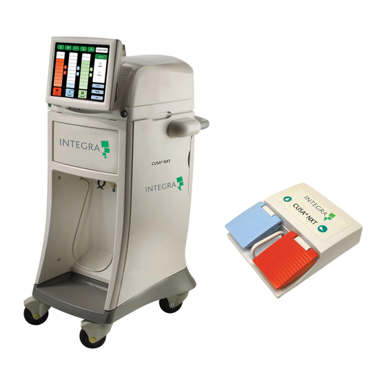
List of CUSA NXT Components The CUSA NXT System consists of the Console, Footswitch, and Service Module (if applicable). Console Service Module About the Console The Console provides power to the selected ultrasonic handpieces. A touch screen monitor is used to control the aspiration, irrigation and ultrasonic power delivered to handpiece. -
Page 28: About The Footswitch
Support for Service Module The Console supports the optional Service Module that provides suction and waste collection (see page 21). About the Footswitch The Footswitch contains two pedals for controlling the power (left side, orange) and Fast Flush (right side, blue). Power pedal Fast Flush pedal The Footswitch also provides a 6m cord that connects to the Footswitch port... - Page 29 Using Other Suction Source Types If the CUSA NXT Console will not be used with the Service Module, then the Console will require another suitable source of suction and waste collection. Wall or ceiling mounted vacuum points in the operating room or a...
-
Page 30: About The Handpieces And Wrench Sets
About the Handpieces and Wrench Sets Warning Only use Integra handpieces and accessories with the CUSA NXT System. The use of non-Integra handpieces or accessories may result in patient injury. Non-Integra handpieces or accessories are not supported and are not covered by warranty. -
Page 31: About The Tubing Kits
For Neuro handpieces 1523000M5, 1523000M7, 1523000M8, 1523000M9. 1529056 For MicroSurgical handpieces 1529000M1, 1529000M2. About the Tubing Kits The CUSA NXT System requires a supply of sterile tubing kits. Sterile tubing kits have a three year shelf life. Part # Description 1517079... -
Page 32: About The Sterile And Non-Sterile Tips
About the Sterile and Non-Sterile Tips For Neuro Handpieces Sterile Tip Sets The CUSA Selector sterile tip sets include a sterilized tip and flue. Sterile tips sets have a five year shelf life. The part numbers are: Part # Description 1523225 24 kHz Neuro Long Sterile Tip Set (5 packs. -
Page 33: For Standard Handpieces
Non-Sterile Tip Sets The CUSA Selector non-sterile tip sets include a non-sterile tip and flue. Non-sterile tips and flues must sterilized before use according to the instructions in Chapter 6. The part numbers are: Part # Description 1523067 24 kHz Neuro Tip Set for Neuro Long and Neuro Short (5 packs. Each pack contains one tip and one flue) 1529066 24 kHz MicroSurgical Tip Set (5 packs. -
Page 34: Summary Of Operating Safety Precautions
Warning When the handpiece is connected to a CUSA NXT System that is powered on, but the handpiece is not in use, keep the handpiece away from the patient. Place the handpiece on a sterile, flat, dry, nonconductive, and highly visible surface. -
Page 35: Sterilizing Backup Handpieces
Warnings and Hazards when Using the System Class 1 Type CF The CUSA NXT System is Class 1 type CF Patient connected electrically isolated equipment (reference IEC 60601). Warning Risk of explosion. - Page 36 Inspecting Handpiece Tips for Damage Warning Do not use a damaged handpiece with the CUSA NXT System.This may result in injury to the patient or surgical personnel. A damaged handpiece must be returned to the manufacturer for repair. Do not attempt to dismantle the rear handle sections of the handpieces;...
- Page 37 Use of the handpieces in a damaged condition can result in an electric shock hazard. Warning Failure to maintain the CUSA NXT System in accordance with the instructions in this manual can compromise safety. Warning Use the single use CUSA Selector tubing, and single use tips and flue sets once only.
-
Page 38: Requirements For Servicing The System
Requirements for Servicing the System Do not remove any instrument covers on the system or touch screen monitor. The CUSA NXT Console contains no user serviceable parts and the system must be serviced only by qualified Integra service engineers. Interference with the Console by any other personnel may invalidate the warranty and may result in injury. - Page 39 This page is intentionally left blank. ® 32 • Chapter 2 • CUSA NXT System Setup and Components...
-
Page 40: About The Console Functionality
HAPTER SING THE ONSOLE ERVICE ODULE ANDPIECES About the Console Functionality ..............33 Using the Touch Screen Monitor ..............38 Using the Footswitch Pedals ................ 36 About the Service Module Functionality ............. 44 About the Handpiece Functionality ............. 47 List of Handpieces ..................47 About the Console Functionality ®... -
Page 41: About The Left Console Panel
About the Left Console Panel The following table describes the components and connection points on the left side of the Console. Component Description Irrigation Pump A peristaltic pump that pumps irrigant from the IV bag to the handpiece. This pump clamps into place across the irrigation tube of the disposable tubing set. Note that the direction of tubing connections to the pump are illustrated on the panel. -
Page 42: About The Rear Console Panel
Service Module. An appliance coupler can be used to isolate the system from the mains power source. Notice: To isolate the CUSA NXT from the AC power supply, you must unplug the Console from the power source. Power Button Turns the CUSA NXT Console on and off. -
Page 43: Connecting Handpieces To The Console
Connecting Handpieces to the Console The Console contains 3 color-coded ports for connecting the different types of handpieces. Two of the ports appear on the front panel, while the third port appears on the left panel. 24 kHz MicroSurgical 35 kHz Handpiece Handpiece Only connect one handpiece to the system at the same time. - Page 44 (right, blue). • Fast Flush Power pedal Fast Flush pedal To connect the Footswitch to the Console, attach the Footswitch cord to the appropriate port on the rear of the Console panel. Align the red dot on the Footswitch plug with the red dot on the Footswitch connection point, and gently insert the plug until you hear a clicking sound.
-
Page 45: Using The Touch Screen Monitor
Stop aspiration (until the pedal is released). • Using the Touch Screen Monitor The CUSA NXT Console provides a touch screen monitor for viewing and controlling the power, irrigation, and aspiration levels during an ultrasonic case. 38 • Chapter 3 • Using the Console, Service Module, and Handpieces... -
Page 46: Status/Alarm Symbols
For instructions on maintaining the touch screen, see page 80. Status/Alarm Symbols The CUSA NXT System activates an alarm to indicate a technical problem with the system. All alarms on the CUSA NXT are technical, low-priority alarms, for example, mechanical or equipment related. There are no physiological alarms on the CUSA NXT System. - Page 47 Warning Ignoring alarms on the CUSA NXT System while continuing to use the system may result in injury to the patient and/or surgical personnel, or equipment damage.
-
Page 48: Adjusting The Ultrasonic Control Scales
Adjusting the Ultrasonic Control Scales Use the , and scales to control the major power irrigation aspiration ultrasonic settings during a case. Adjusting the Power Level Use the scale (orange) to specify the ultrasonic power output (tip power amplitude). The power settings range between 10% and 100%. The default power setting is 10%. - Page 49 Adjusting the Irrigation Level Use the scale (blue) to specify the rate irrigation of irrigation that will be delivered to the handpiece. The irrigation rate ranges between 2 and 20 ml/minute. The default flow is 3 ml/min. The accuracy of the irrigation flow is +/- 20% of setting or +/-1 ml/min, whichever is greater.
-
Page 50: Verifying General Ultrasonic Information
Adjusting the Aspiration Level Use the scale (green) to specify the aspiration aspiration rate of the total available suction of the source of vacuum employed. The aspiration rate ranges from 15% to 100%. The default setting for aspiration is 100%. The accuracy of the aspiration rate is +/-50 mm Hg of available aspiration. -
Page 51: Displaying Menus For Prime Mode, Customized Settings, And Online Help
(see page 2). About the Service Module Functionality The Service Module provides a convenient, mobile base for the CUSA NXT Console, as well as a source of suction and waste collection. It is controlled from the Console and has no user accessible controls. - Page 52 An international standard inlet which accepts the power cord supplied with the Console. Power Switch Turns the power to the Service Module on and off. This switch must be turned on to power on the CUSA NXT Console. Chapter 3 • Using the Console, Service Module, and Handpieces • 45...
- Page 53 For instructions on using the Service Module (or other sources for suction and waste removal) during a surgical procedure, see page 59. Rear View of Console Attached to Service Module Console Service Module Caution Do not store anything in the storage area in the back of the Console while the system is running.
-
Page 54: About The Handpiece Functionality
Handle Contains the piezoelectric transducer which includes an array of piezo ceramic elements to convert the power signal from the CUSA NXT Console into mechanical vibration at 24 kHz or 35 kHz depending on the handpiece type. Piezoelectric Transducer Generates negligible heat and requires no external cooling system. -
Page 55: List Of Standard Handpieces
List of Standard Handpieces 24 kHz Straight Handpiece (part # 1523000M1) Part # Description Picture Transducer assembly 1523013 Standard tip, non-sterile, each 1 1523042 Flue (disposable), non-sterile, single use, box of 20 1523017 Straight shroud, each1 24 kHz Angled Handpiece (part # 1523000M2) Part # Description Picture... - Page 56 35 kHz Straight Handpiece (part # 1523000M3) Part # Description Picture Transducer assembly 1523014 Standard tip, non-sterile, each 1 1523043 Flue (disposable), non-sterile, single use, box of 20 1523018 Straight shroud, each 1 24 kHz Laparoscopic Handpiece (part # 1523000M6) Part # Description Picture...
-
Page 57: List Of Neurosurgical Handpieces
List of Neurosurgical Handpieces 24 kHz Neurosurgical Short Handpiece (part # 1523000M7)Selector Part # Description Picture Transducer assembly 1523067 24 kHz Ultrafine ™ MicroTip Set (includes Flue) non-sterile, 5 packs, where each pack contains 1 tip and 1 flue 1523056 24 kHz Neuro Short Tip Set (1 tip and 1 flue) ™... - Page 58 Notice • The CUSA NXT Bone Tips can only be used with the CUSA NXT System. They cannot be used with the CUSA Selector System. • The CUSA NXT Bone Tips can only be used with the 24 kHz Neurosurgical handpiece (part # 1523000M7).
- Page 59 24 kHz Neurosurgical Long Handpiece (part # 1523000M5) Part # Description Picture Transducer assembly ™ 1523067 24kHz Ultrafine MicroTip (single use) non-sterile, 5 packs, where each pack contains 1 tip and 1 flue 1523225 Neuro Long Tip Set (single use) sterile, 5 packs, where each pack contains 1 tip and 1 flue 1523221...
- Page 60 The flue and extension shroud are packaged in either a sterile or non-sterile Tip Set. Notice • The Extended Length Tips are compatible with both the CUSA NXT and CUSA Selector Systems. • The Extended Length Tip can only be used with the 35 kHz NeuroSurgical Handpiece (part # 1523000M9).
-
Page 61: List Of Microsurgical Handpieces
List of MicroSurgical Handpieces 24 kHz MicroSurgical Handpiece (part # 1529000M2) Part # Description Picture Transducer assembly 1529066 MicroSurgical Tip Set (single use), non-sterile, 5 packs, where each pack contains 1 tip and 1 flue 1529165 MicroSurgical Tip Set (single use), sterile, 5 packs, where each pack contains 1 tip and 1 flue... -
Page 62: Chapter 4 Preparing The Cusa Nxt System For Surgery
Appropriate handpiece wrench set • The CUSA NXT System requires a minimum of one hour exposure at its operating temperature range before you use it. Make sure that the system is located in the surgical room at least an hour before use. -
Page 63: Assembling The Handpieces
Caution The manifold tubing utilizes PVC tubing which is known to contain DEHP in a portion of the drainage path. The risk of exposure to pregnant (breast feeding) women, children and peri-pubescent males is not considered significant for the following reason(s): Saline solution running through the tubing, as irrigation, comes into contact with the surgery site during the tissue ablation process. - Page 64 Reposition the handpiece into the holder, securing Flat 1 ( ) of the angled extension into the designated slot of the holder. Using your fingers, screw the tip into the angled extension. Using the wrench, tighten the tip by turning it clockwise. Remove the handpiece from the holder.
- Page 65 Attach the clear flue onto the shroud until firmly placed in position. See page 36 for information on connecting the handpiece to the Console. The handpiece is now ready for use. ® 58 • Chapter 4 • Preparing the CUSA NXT for Surgery...
-
Page 66: Preparing The System
Preparing the System Preparing the system for surgery requires setting up the following items: Suction source • IV Bag • Tubing Kits • Footswitch • Prepare the Suction Source Depending on the type of suction source being used, do one of the following: •... -
Page 67: Prepare The Iv Bag
Connect tubing from the contamination guard ( ) to the vacuum port ( on the canister. Prepare the IV Bag Lift the IV pole on the rear of the Console to an elevated position and turn the knurled locking ring clockwise to secure the extended section. Place the sterile intravenous fluid container onto the hook at the end of the pole. - Page 68 Retain the yellow stylet and white hose clips in the sterile field. Notice All of the handpiece and tubing kit components in the CUSA NXT System are not manufactured with dry natural rubber or natural rubber latex. Connect the tubing to the handpieces. Attach the double lumen tube from...
-
Page 69: Connect Tubing To Console
Connect Tubing to Console Warning To avoid injury to surgical personnel, keep fingers away from the pump rollers. Follow the diagram on the side label of the Console: Notice When preparing the tubing set, connect the tubing to the pump prior to attaching the irrigation supply. -
Page 70: Position The Footswitch
Priming the Handpieces Automatic priming is a feature on the CUSA NXT System. Manual methods for priming used with previous versions of Selector may still be performed, however, you must at least start and then stop the initial prime cycle in order to proceed with system operation. - Page 71 On the prime screen, press the start button; the CUSA NXT will start to prime the handpiece and display a progress bar. To stop the priming process at any time, press the button. stop Caution Do not power the CUSA Selector handpiece without fully priming the handpiece with irrigant, i.e.
-
Page 72: Testing The Alarm Tone
38. Testing the Alarm Tone To verify the alarm tone functions correctly, you must intentionally trigger an alarm on the CUSA NXT System, for example, disconnect the footswitch from Console: Disconnect the footswitch from the Console at the footswitch connector. - Page 73 This page is intentionally left blank. ® 66 • Chapter 4 • Preparing the CUSA NXT for Surgery...
-
Page 74: Chapter 5 Operating The Cusa Nxt System During Surgery
Caution Before surgery, apply the brakes locks to all wheels on the Service Module to stop the wheels from rolling. Note the following guidelines when using the CUSA NXT during surgery: ® NXT During Surgery • 67 Chapter 5 • Operating the CUSA... - Page 75 Increasing the setting (orange) increases cell disruption at the • power handpiece tip. Increasing the setting (blue) increases the irrigation flow. • irrigation Increasing the setting (green) increases the suction at the • aspiration handpiece tip. During the surgical procedures, you may adjust these variables by adjusting the appropriate scales on the touch screen.
-
Page 76: Warnings Relating To The Tips During Surgery
Warning CUSA NXT tips utilize silicone flues. Compressing the flue against the side of the vibrating surface along the length of the tip can cause excessive heating and potential hazard to adjacent tissue, such as burns. -
Page 77: Customizing The User Settings
Warning Excessive loading of CUSA NXT tips at the surgical site can induce heating due to vibration and acoustic power transmissions into adjacent tissue that may not be easily visualized due to anatomical constraints. Thermal management of the surgical site with the aid of the appropriate irrigation and aspiration settings is essential. - Page 78 The next time the system is turned on, the CUSA NXT System will restore these values. To restore the default settings, press presets on the settings panel and choose option.
- Page 79 This page is intentionally left blank. ® 72 • Chapter 5 • Operating the CUSA NXT During Surgery...
-
Page 80: Chapter 6: Disassembly And Sterilization Of Cusa ® Nxt System
HAPTER ISASSEMBLY AND TERILIZATION OF ® CUSA NXT S YSTEM Dismantling the System After Surgery ............73 Cleaning the Handpieces After Surgery ............75 Sterilizing Components and Maintaining the Handpieces......77 Maintaining the Touch Screen Monitor ............80 Handling and Transporting the System............81 Notice The handpiece and the initially pre-packaged non-sterile tip and flue(s) are supplied non-sterile and must be disassembled and sterilized before use. - Page 81 Lower the irrigation pole by turning the knurled locking ring counter-clockwise. Warning Electric Shock Hazard – Always unplug the CUSA NXT System before cleaning Warning Do not allow fluids to enter the Console or Service Module.
-
Page 82: Cleaning The Handpieces After Surgery
Cleaning the Handpieces After Surgery Disassembling the Handpieces After surgery and prior to sterilization, disassemble and clean the CUSA ® Selector handpiece: ® In a sink or bowl, prepare a cleaning solution containing warm water with detergent. This is necessary for cleaning the handpiece parts. Consult hospital policy for approved cleaning materials. - Page 83 Reposition the handle of the handpiece in the holder cut out and using the same wrench set as before, loosen the angled extension by turning it counterclockwise. Notice If you are using either a straight or laparoscopic handpiece, the angled extension is not required.
-
Page 84: Sterilizing Components And Maintaining The Handpieces
Note that sterilization systems in use at hospitals are chamber specific. As a result, Integra LifeSciences can only recommend a reference for hospitals to aid the sterilization parameters set for your hospital system. Integra LifeSciences has validated the following sterilization cycles for your consideration. -
Page 85: Disinfecting The Handpieces
Validations for Steam Sterilization Integra LifeSciences has validated steam sterilization. The challenge organism used was > 1 x 10 Bacillus stereothermophilus. Biological indicators were placed in the areas identified as the most difficult to sterilize, representing worst case conditions. -
Page 86: Maintaining The Handpieces
Maintaining the Handpieces In addition to the post-operative care of the CUSA NXT System described on pages 73 and 75, further maintenance steps recommended by the manufacturer are as follows: General Maintenance At 6 Month Intervals Remove and replace the contamination guard every six months, or when the filter changes color (part # NXT00005). -
Page 87: Maintaining The Touch Screen Monitor
Service Centers Service Centers Address United States Integra NeuroSciences 5965 Pacific Center Blvd.Suite 714 San Diego, CA 92121 Tel: 858-455-1115 Fax: 858-455-8298 E-mail: sandiegoservicecenter@integralife.com International Integra NeuroSciences Halskestrasse 25 Ratingen 40880 Germany Tel: +49 2102 5535 6150 Fax: +49 2102 942 4872 E-mail: emea.techservice@integralife.com... -
Page 88: Handling And Transporting The System
If you need to move/relocate the CUSA NXT System within the environment of the Healthcare Facility, note the guidelines below. The CUSA NXT System requires a minimum of one hour exposure at its operating temperature range before you use it; make sure that the system is located in the surgical room at least an hour before use. -
Page 89: Shipping Instructions
Handpieces making sure that the contents will be well protected against dropping and manhandling. It is strongly advised that the original cardboard packaging is only used once for re-packing. If you do not have suitable packaging please contact your Integra representative. ®... -
Page 90: Chapter 7: Troubleshooting The Cusa ® Nxt System
® CUSA HAPTER ROUBLESHOOTING THE YSTEM About the Troubleshooting Process............83 Problems Powering the System On and Off ..........83 Responding to Alarms .................. 84 Troubleshooting Aspiration Problems ............85 Troubleshooting Irrigation Problems ............86 Troubleshooting Ultrasonic Power Problems..........87 About the Troubleshooting Process ®... -
Page 91: Responding To Alarms
Responding to Alarms All alarms on the CUSA NXT are low-priority, technical alarms; operator awareness is required. Symbol Alarm Causes Recommendations Tubing not attached to suction Attach the tubing to the suction Aspiration canister. canister. • Tighten the tip. Power Improper tip assembly. -
Page 92: Troubleshooting Aspiration Problems
Troubleshooting Aspiration Problems Problem Causes Recommendations Insufficient Aspiration Service Module is unplugged. Plug in the Service Module. Tubing is routed incorrectly. See the diagram on the Console for correct routing. Ensure that the filter is fully inserted. Tubing is not connected to the Connect the tubing to the suction source. -
Page 93: Troubleshooting Irrigation Problems
Troubleshooting Irrigation Problems Problem Causes Recommendations Excessive Irrigation Incorrect rate set. Set the appropriate rate (normally between 2 and 6 ml/min). Tubing is not routed correctly. See the diagram on the Console for the correct routing. Irrigation pump is not fully closed. Close the irrigation pump. -
Page 94: Troubleshooting Ultrasonic Power Problems
Troubleshooting Ultrasonic Power Problems Problem Causes Recommendations Insufficient Power Footswitch is unplugged. Plug in the Footswitch. Power level is not set appropriately. Set the power level appropriately (normally set between 70% and 100%). Improper tip assembly. • Detach the tip and reassemble the handpiece;... - Page 95 This page is intentionally left blank. ® 88 • Chapter 7 • Troubleshooting the CUSA NXT System...
-
Page 96: Appendix A: Technical Specifications
PPENDIX ECHNICAL PECIFICATIONS ® Specifications for the CUSA NXT System..........93 Electrical Safety ..................... 91 Standards and IEC Classifications .............. 93 Manufacturer’s Declaration Table ..............94 Specifications for the CUSA NXT System ® Console Specifications Parameter Specification Height 31.8 cm (12.5 in) Width 45.7 cm (18 in) Depth... - Page 97 Footswitch Specifications Parameter Specification Height 6 cm (2.4 in) Width 19.5 cm (7.7 in) Depth 22 cm (8.7 in) Weight 2 kg (4.4 lbs) Length 5.81 m (19 ft) Input Power Source Specifications Parameter Specification Power Requirements 115-230 V~, 50-60 Hz (Console) 115/230 V~, 50-60 Hz/50 Hz (Service Module) Power Consumption...
-
Page 98: Electrical Safety
(recast). Electrical Safety The CUSA NXT System requires a single grounded electrical outlet providing power at 115 -230 V~, 50-60 Hz (Console),115/230 V~, 50-60 Hz/50 Hz (Service Module) . The Console operates on any voltage between 115 V and 230V. - Page 99 2.5 amps at 240 V and 5 amps at 100 V. The removable power cord supplied with the system provides the power. Correct grounding of the CUSA NXT Console is essential for safe operation. The Console is grounded via the power cord; verify that this cord is connected to a properly grounded power receptacle of appropriate rating.
-
Page 100: Standards And Iec Classifications
The CUSA NXT System is manufactured by Integra LifeSciences Corporation. Integra LifeSciences Corporation operates a quality system that complies with ISO 13485, CMDCAS. International Bodies The CUSA NXT System has been designed, constructed, and approved to the requirements of the following international bodies: International Electrotechnical Commission (IEC) •... -
Page 101: Manufacturer's Declaration Table
Guidance and Manufacturer’s Declaration - Electromagnetic Emissions The CUSA NXT System is intended for use in the electromagnetic environment specified below. The customer or the user of the CUSA NXT System should assure that it is being used in such an environment. - Page 102 ) for 0.5 cycle Standard commercial or hospital environment. If the user voltage variations of the CUSA NXT System requires continued • 40% (60% dip in or power supply operation during power mains interruptions, it ) for 5 cycles...
- Page 103 Guidance and Manufacturer’s Declaration - Electromagnetic Immunity The CUSA NXT System is intended for use in the electromagnetic environment specified below. The customer or the user of the CUSA NXT System should assure that it is being used in such an environment.
- Page 104 To assess the electromagnetic environment due to fixed RF transmitters, an electromagnetic site survey should be considered. If the measured field strength in the location in which the CUSA NXT System is used exceeds the applicable RF compliance level above, the CUSA NXT System should be observed to verify normal operation. If abnormal performance is observed, additional measures may be necessary, such as re-orientating or relocating the CUSA NXT System.
- Page 105 This page is intentionally left blank. 98 • Appendix A • Technical Specifications...
-
Page 106: Appendix B: Warranty
Section 3 of this Warranty, so that the Equipment conforms with the Specifications defined in the CUSA NXT Ultrasonic Surgical Aspirator Operator's Manual, as such Operator's Manual may be modified by Integra from time to time. - Page 107 Consoles and service module or replace a Console and service module by a new or refurbished Console and service module (at the discretion of Integra), as the case may be, and where not possible Integra shall arrange and pay to ship the affected Equipment to the designated repair facility, and shall repair the affected Equipment.
- Page 108 Force Majeure. Notwithstanding anything to the contrary herein 5. 3 contained, if the performance of the Warranty by Integra or Customer or any obligation of Integra or Customer hereunder is prevented, restricted or interfered with by reason of fire, explosion, act of God, labor disputes or accidents affecting performance under the Warranty, or war, Appendix B •...
- Page 109 Integra or Customer, then and in that event Integra or Customer, as the case may be, shall promptly notify the other party hereto of the resulting difficulties therefrom, and any of the foregoing events shall excuse any performance required under the Warranty.
-
Page 110: Index
NDEX Numerics color codes, handpieces 36 24 kHz handpieces compliance standards 93 – – list of neurosurgical 50 components, list of 20 – list of standard 48 Console 35 kHz handpieces cleaning the 74 – list of neurosurgical 53 functionality of 33 –... - Page 111 languages, changing onscreen 71 general alarms, responding to 84 laparoscopic handpieces 49 German, changing language to 71 Latex free components 31 grounding point, Console’s 35 leakage, low frequency 91 grounding, electrical 91 left Footswitch pedal (see “Power Footswitch pedal") – levels, controlling ultrasonic 41 handpieces, types of 24 kHz...
- Page 112 – initial setup with Console 19 preparing 60 technical specifications for 89 tubing pathway, symbols for 14 servicing turning off system 83 contacting Integra 80 requirements for 31 service centers 80 ultrasonic power – settings button 44 controlling 41 shroud, handpiece 47...
- Page 113 This page is intentionally left blank. 106 • Index...
Need help?
Do you have a question about the CUSA NXT and is the answer not in the manual?
Questions and answers