
Related Manuals for Avaya CallPilot 1005r


Summary of Contents for Avaya CallPilot 1005r
- Page 1 Avaya CallPilot® 1005r Server Maintenance and Diagnostics NN44200-704, 01.12 December 2010...
- Page 2 Product provided by Avaya including the selection, arrangement and While reasonable efforts have been made to ensure that the design of the content is owned either by Avaya or its licensors and is information in this document is complete and accurate at the time of protected by copyright and other intellectual property laws including the printing, Avaya assumes no liability for any errors.
- Page 3 Council for Interference by Information Technology Equipment (VCCI). If this equipment is used in a domestic environment, radio disturbance may occur, in which case, the user may be required to take corrective action. Avaya CallPilot® 1005r Server Maintenance and Diagnostics December 2010...
- Page 4 Avaya CallPilot® 1005r Server Maintenance and Diagnostics December 2010...
-
Page 5: Table Of Contents
Chapter 1: Customer service....................9 Getting technical documentation........................9 Getting product training.............................9 Getting help from a distributor or reseller......................9 Getting technical support from the Avaya Web site..................10 Chapter 2: Outlining maintenance and diagnostics activities..........11 In this chapter..............................11 1005r server features............................11 Front control panel and features........................11 Back panel controls and features........................12... - Page 6 If a diagnostic test fails or cannot be run......................55 Viewing the last diagnostics result........................56 Working with the Multimedia Monitor......................57 Working with the Channel Monitor........................58 Chapter 7: Using Avaya CallPilot® system utilities.............59 In this chapter..............................59 Overview.................................59 Accessing the system utilities.........................60 Diagnostics Tool..............................60 Avaya CallPilot®...
- Page 7 M1/Avaya Communication Server 1000 switch connectivity.................103 Taking safety precautions..........................104 Locating the voice processing boards......................104 DSP numbering and location........................105 DSP numbering MPB96 boards........................105 Replacing an MPB96 board..........................107 Requirements..............................108 Upgrading to high capacity..........................113 Requirements..............................114 Avaya CallPilot® 1005r Server Maintenance and Diagnostics December 2010...
- Page 8 Requirements for upgrading or reconfiguring the BIOS................122 BIOS settings..............................124 Using system event logs..........................126 Maintaining the onboard video and network cards..................128 Network card failure............................128 Video card failure............................128 Indicators for video card failure........................128 Index............................129 Avaya CallPilot® 1005r Server Maintenance and Diagnostics December 2010...
-
Page 9: Chapter 1: Customer Service
Chapter 1: Customer service Visit the Avaya Web site to access the complete range of services and support that Avaya provides. Go www.avaya.com or go to one of the pages listed in the following sections. Navigation • Getting technical documentation on page 9 •... -
Page 10: Getting Technical Support From The Avaya Web Site
Customer service Getting technical support from the Avaya Web site The easiest and most effective way to get technical support for Avaya products is from the Avaya Technical Support Web site at www.avaya.com/support. Avaya CallPilot® 1005r Server Maintenance and Diagnostics... -
Page 11: Chapter 2: Outlining Maintenance And Diagnostics Activities
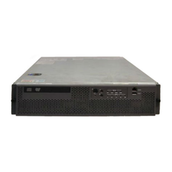
When the bezel cover is on, the DVD connections, controls, alarm LEDs, and status LEDs are visible. With the bezel cover removed, both hard drives, the peripheral DVD/CD/ CDRW drive, the antistatic connection, and the front serial port are accessible. Avaya CallPilot® 1005r Server Maintenance and Diagnostics December 2010... -
Page 12: Back Panel Controls And Features
The following diagram shows the back panel controls. The features on the right are the AC power supply banks. The PCI card brackets are in the middle of the back panel while the connectors and ports are along the bottom and left side. Avaya CallPilot® 1005r Server Maintenance and Diagnostics December 2010... - Page 13 USB 1 Numbered (1, 2, 3) from top to bottom. Power supply 1 USB 0 Power supply 2 Server management LAN port PS/2 mouse and keyboard External SCSI tape drive connectors Avaya CallPilot® 1005r Server Maintenance and Diagnostics December 2010...
-
Page 14: Maintenance And Diagnostics Overview
If a failure occurs on any of these components it is not reported by the server LEDs or by ISM. Replacement parts Before replacing any parts on your server, refer to the Avaya product catalog for the part codes. Caution: Risk of system damage The use of parts that are not supplied by Avaya can cause serious system problems or void your Avaya warranty. -
Page 15: Preparing For Maintenance Activities
Planning and Engineering Avaya CallPilot® Planning and Engineering Guide (NN44200-200) Avaya CallPilot® Network Planning Guide (NN44200-201) Avaya Communication Server 1000 Converging the Data Network with VoIP Fundamentals (NN43001-260) Solution Integration Guide for Avaya Communication Server 1000/CallPilot®/NES Contact Center/Telephony Manager (NN49000-300) Installation and Configuration Avaya CallPilot®... - Page 16 Administration Guide (NN44200-305) Administration Avaya CallPilot® Administrator Guide (NN44200-601) Avaya CallPilot® Software Administration and Maintenance Guide (NN44200-600) Avaya Meridian Mail to Avaya CallPilot® Migration Utility Guide (NN44200-502) Avaya CallPilot® Application Builder Guide (NN44200-102) Avaya CallPilot® Reporter Guide (NN44200-603) Maintenance Avaya CallPilot® Troubleshooting Reference Guide (NN44200-700) Avaya CallPilot®...
- Page 17 (NN44200-116) Avaya CallPilot® Multimedia Messaging User Guide (NN44200-106) Avaya CallPilot® Speech Activated Messaging User Guide (NN44200-107) Avaya CallPilot® Desktop Messaging User Guide for Microsoft Outlook (NN44200-103) Avaya CallPilot® Desktop Messaging User Guide for Lotus Notes (NN44200-104) Avaya CallPilot® Desktop Messaging User Guide for Novell Groupwise (NN44200-105) Avaya CallPilot®...
- Page 18 Outlining maintenance and diagnostics activities Avaya CallPilot® Desktop Messaging User Guide for My CallPilot (NN44200-109) Avaya CallPilot® Voice Forms Transcriber User Guide (NN44200-110) The Map was created to facilitate navigation through the suite by showing the main task groups and the documents contained in each category. It appears near the beginning of each guide, showing that guide's location within the suite.
-
Page 19: Chapter 3: Troubleshooting Your Avaya Callpilot® System
• basic hardware check (front panel LEDs) • Power-On Self-Test (POST) diagnostics • SCSI hard drive controller diagnostics or RAID controller diagnostics These diagnostics are available at initial system startup or after any 1005r server reset. Avaya CallPilot® 1005r Server Maintenance and Diagnostics December 2010... -
Page 20: Basic Hardware Check
11 for details of the front panel. 3. Check that all the alarm LEDs (C to F) are illuminated amber for a few seconds. If not, refer to the following table for functional descriptions of fault LEDs. Avaya CallPilot® 1005r Server Maintenance and Diagnostics December 2010... -
Page 21: Power-On Self-Test Diagnostics
A power supply fault indicates that one of the power supplies is not providing power. The MJR LED is also lit. 4. Boot the server by pressing the power button on the front of the Avaya CallPilot 1005r server. 5. Observe the following server actions: •... -
Page 22: Interpreting Post Diagnostics
A beep code is a series of separate tones, each equal in length. Important: If your system emits POST beep codes, record the beep code sequence and then call Avaya technical support before attempting to correct the problem. Ensure you have the required system information. -
Page 23: Interpreting Bios Error Messages
When a recoverable error occurs during the POST, an error message appears describing the problem. Important: If BIOS error messages appear, record the error messages and then call Avaya technical support before attempting to correct the problem. BIOS error messages BIOS error messages appear on the video monitor. - Page 24 A parity error occurred on an offboard card. This error is followed by the card address. On Board Parity Error A parity error occurred in onboard memory. This error is followed by the card address. Avaya CallPilot® 1005r Server Maintenance and Diagnostics December 2010...
-
Page 25: When A Processor In The 1005R Server Is Disabled
If CallPilot fails to boot to Windows, follow these steps: 1. Make a note of any diagnostic codes. 2. Press the power switch to restart the server. 3. View the diagnostic codes for failures during the boot sequence. Avaya CallPilot® 1005r Server Maintenance and Diagnostics December 2010... -
Page 26: Interpreting Hard Drive Leds
127. 5. Refer to the Troubleshooting Guide (NN44200-700) for other suggestions. If you still cannot determine the cause of the startup failure, call your Avaya technical support representative. To determine why CallPilot fails to come into service If CallPilot fails to come into service, follow these steps: 1. -
Page 27: Chapter 4: Using Windows Online Diagnostic Tools
This section describes how to access the run-time online diagnostic tools provided by the Windows server software. Use the following tools when a serious problem prevents the use of the Avaya CallPilot® diagnostic tools that are available in Avaya CallPilot Manager: • Windows Event Viewer •... -
Page 28: Viewing Event Logs
You can view the Hardware system event log from ISM, or by booting from the CallPilot image DVD and selecting the system event log from the menu. If the server does not boot up, use the Avaya CallPilot Image Utilities on the DVD to view system event logs. Refer to Using system event logs on page 126. - Page 29 2. To view a log, click the name of the log in the left pane of the window. The following illustration shows an example of the Application log. Figure 5: Application log The following illustration shows an example of the System log. Avaya CallPilot® 1005r Server Maintenance and Diagnostics December 2010...
- Page 30 Use the description to help determine how to resolve errors. Note: If the error persists or the error description does not suggest a solution, contact your Avaya support representative. 5. Click OK. Avaya CallPilot® 1005r Server Maintenance and Diagnostics December 2010...
-
Page 31: Using Tcp/Ip Diagnostic Tools
If you run the command without flags, it displays the IP address, subnet mask, and default gateway for each adapter bound to TCP/IP. ipconfig command syntax The ipconfig command uses the following syntax: ipconfig /[ ] Avaya CallPilot® 1005r Server Maintenance and Diagnostics December 2010... -
Page 32: The Ping Command
[-t] [-a] [-n count] [-l size] [-f] [-i TTL] [-v TOS] [-r count] [-s count] [[-j host-list] | [-k host-list]] [-w timeout] destination-list Table 6: ping command extensions Parameter Description Pings the specified host until interrupted. Avaya CallPilot® 1005r Server Maintenance and Diagnostics December 2010... -
Page 33: The Tracert Command
Result: The system displays the ping results. 4. Type Exit to exit the Command Prompt dialog box and return to Windows. The tracert command This utility determines the route taken to a destination. Avaya CallPilot® 1005r Server Maintenance and Diagnostics December 2010... -
Page 34: How Tracert Works
Specifies the maximum number of hops to search for the target. -j host-list Specifies a loose source route along the host list. -w timeout Waits the number of milliseconds specified by the timeout for each reply. Avaya CallPilot® 1005r Server Maintenance and Diagnostics December 2010... -
Page 35: The Arp Command
The arp command displays and modifies the IP-to-physical address translation tables used by Address Resolution Protocol (ARP). ARP command syntax The ARP command uses the following syntax: arp -s inet_addr eth_addr [if_addr] arp -d inet_addr [if_addr] arp -a [inet_addr] [-N if_addr] Avaya CallPilot® 1005r Server Maintenance and Diagnostics December 2010... -
Page 36: Arp Command Parameters
Result: The system runs the arp command. 4. Type Exit to exit the Command Prompt dialog box and return to Windows. The nbtstat command The nbtstat command displays protocol statistics and current TCP/IP connections using NBT. Avaya CallPilot® 1005r Server Maintenance and Diagnostics December 2010... -
Page 37: Nbtstat Command Syntax
To run the nbtstat command from Windows 1. Click Start > Programs > Accessories > Command Prompt. Result: The Command Prompt dialog box appears. 2. Type nbtstat with the required parameters. Avaya CallPilot® 1005r Server Maintenance and Diagnostics December 2010... -
Page 38: The Netstat Command
To run the netstat command from Windows 1. Click Start > Programs > Accessories > Command Prompt. Result: The Command Prompt dialog box appears. 2. Type netstat with the required parameters. Avaya CallPilot® 1005r Server Maintenance and Diagnostics December 2010... -
Page 39: Using The Chkdsk Utility
Optional parameter to fix errors on the disk. Optional parameter to display the full pathname of every file on the disk. Optional parameter to locate bad sectors and to recover readable information. Avaya CallPilot® 1005r Server Maintenance and Diagnostics December 2010... - Page 40 2. Type chkdsk <drive letter:> (for example, chkdsk c:). 3. Press Enter. Result: The system runs the chkdsk utility. 4. Type Exit to exit the Command Prompt dialog box and return to Windows. Avaya CallPilot® 1005r Server Maintenance and Diagnostics December 2010...
-
Page 41: Chapter 5: Monitoring Server Hardware
• Receive alert messages when the sensor values are out of range, or when a performance threshold is reached. Refer to the Help files in the ISM screen for more information. Avaya CallPilot® 1005r Server Maintenance and Diagnostics December 2010... - Page 42 Monitoring server hardware Avaya CallPilot® 1005r Server Maintenance and Diagnostics December 2010...
-
Page 43: Chapter 6: Monitoring Multimedia Hardware
58 Understanding fault management Fault management is a subsystem within Avaya CallPilot® that detects and notifies you of potential or real hardware problems with the multimedia hardware. Avaya CallPilot monitors events in the multimedia hardware and raises an alarm when a fault occurs. -
Page 44: Alarm Notification
Typically, you first become aware of a hardware problem when an alarm is raised. All hardware faults produce an alarm (or series of alarms, depending on the problem) in the Alarm Monitor. Avaya CallPilot® 1005r Server Maintenance and Diagnostics December 2010... -
Page 45: Alarm Monitor
3. Click the Event Code for the first Critical or Major alarm. Result: A description of the event appears in a new Web browser window. 4. Review the description and recovery action. Avaya CallPilot® 1005r Server Maintenance and Diagnostics December 2010... -
Page 46: Event Browser
5. Repeat steps on page 46 and on page 46 for more events, if necessary. 6. If the solution to the problem is not apparent, contact your Avaya technical support representative. Note: For information about how to use the Event Browser, see the CallPilot Manager online Help. -
Page 47: Channel And Multimedia Monitors
Disabling call channels If you must take the CallPilot system out of service to perform software or hardware maintenance, Avaya recommends that you disable all call channels first. There are two ways to disable the call channels: • Courtesy stop the channels (preferred method). -
Page 48: Maintenance Activities For Each Component
Viewing the last diagnostics result on page 56 Maintenance activities for each component The following table identifies the maintenance activities you can perform for each component that is listed in the component tree. Avaya CallPilot® 1005r Server Maintenance and Diagnostics December 2010... -
Page 49: Viewing Component States
You can determine the state of a component by looking at the State box in the Maintenance section. State Description Active The component is working and currently involved in processing a call. Disabled The diagnostic failed. Avaya CallPilot® 1005r Server Maintenance and Diagnostics December 2010... -
Page 50: Alert Icons
A problem exists with the selected component. To view the state of a hardware component 1. Run CallPilot Manager and log on. 2. In CallPilot Manager, click Maintenance > Maintenance Admin. Avaya CallPilot® 1005r Server Maintenance and Diagnostics December 2010... -
Page 51: Starting And Stopping Components
To bring an out-of-service component back into service, you must start it. Start and stop components from the Maintenance section on the Maintenance screen. Important: Avaya recommends that, if possible, you courtesy stop a component. Courtesy stop is available at the individual channel level. To courtesy stop CallPilot, use the following: •... -
Page 52: Courtesy Stop
Takes all call processing resources on the selected board out of service. Time switch You cannot perform maintenance administration on the time switch. Multimedia Channel Takes the selected multimedia channel out of service. Avaya CallPilot® 1005r Server Maintenance and Diagnostics December 2010... - Page 53 If you are stopping all components (that is, you are taking the entire system down), ensure that you inform all administrators, desktop messaging users, and Web messaging users so that they can log off their sessions before you proceed. Avaya CallPilot® 1005r Server Maintenance and Diagnostics December 2010...
-
Page 54: Running Integrated Diagnostics
Components with diagnostic tests available The following table identifies the components on which you can run diagnostics. Component Diagnostics available? Replaceable? Media Bus MPB96 board Time switch Multimedia channels Channels DS30X link (cable) Avaya CallPilot® 1005r Server Maintenance and Diagnostics December 2010... -
Page 55: Diagnostic Tests Available For Each Component
Avaya technical support representative, depending on the component. To run a diagnostic test Important: Avaya recommends that you courtesy stop rather than stop a component if possible. For instructions, see Starting and stopping components on page 51. -
Page 56: Viewing The Last Diagnostics Result
You can review the results of diagnostics by clicking the Get Last Results button for a component. To view the last diagnostics result Important: Avaya recommends that you courtesy stop rather than stop a component if possible. For instructions, see Starting and stopping components on page 51. -
Page 57: Working With The Multimedia Monitor
The selected channels change to off-duty or idle status, according to the action you chose. Note: If the buttons are not available, wait a few seconds for the screen to refresh. Avaya CallPilot® 1005r Server Maintenance and Diagnostics December 2010... -
Page 58: Working With The Channel Monitor
The selected channels change to off-duty or idle status, according to the action you chose. Note: If the buttons are not available, wait a few seconds for the screen to refresh. Avaya CallPilot® 1005r Server Maintenance and Diagnostics December 2010... -
Page 59: Chapter 7: Using Avaya Callpilot® System Utilities
61 Session Trace on page 61 CallPilot System Monitor on page 63 Overview The following table lists the Avaya CallPilot system utilities. Utility Description Diagnostics Tool Allows CallPilot startup diagnostics to be enabled or disabled (turned on or off). -
Page 60: Accessing The System Utilities
From the Diagnostics Tool dialog box, select Configuration > Maintenance Startup Diag > Enable. To disable startup diagnostics Important: Avaya recommends that you leave the startup diagnostics turned on. When you disable CallPilot startup diagnostics, you prevent CallPilot from automatically Avaya CallPilot® 1005r Server Maintenance and Diagnostics December 2010... -
Page 61: Pep Maintenance Utility
• the number of messages played or unplayed at the beginning, middle, and end of a session • the number of deleted read messages • the number of deleted unread messages Avaya CallPilot® 1005r Server Maintenance and Diagnostics December 2010... - Page 62 4. Double-click the session type to display the session information. Result: The session type information appears at the bottom of the window. The following example shows Call Answering session type information. Avaya CallPilot® 1005r Server Maintenance and Diagnostics December 2010...
-
Page 63: Callpilot System Monitor
Legend/Help Provides a description of icons and terminology displayed in the System Monitor window. System Monitor is a nondestructive tool that does not alter the behavior of any CallPilot components. Avaya CallPilot® 1005r Server Maintenance and Diagnostics December 2010... -
Page 64: Channel Monitor Tab
Windows Services Control Panel can show that a service is running, but it may not be fully running or in service from a CallPilot perspective. Refer to the Channel Monitor tab in the Systems Monitor for the true status. Avaya CallPilot® 1005r Server Maintenance and Diagnostics December 2010... -
Page 65: Dsps
Click the Legend/Help tab to view descriptions of the multimedia channel icons. Your 1005r server has either one or three MPB96 boards. Each MPB96 board has 12 DSP sections embedded on the board. Avaya CallPilot® 1005r Server Maintenance and Diagnostics December 2010... -
Page 66: Ds30X Links
The DS30X links connect the CallPilot server to the MGate card in the Meridian 1 switch or Avaya Communication Server 1000 system. The DS30X link to the switch is supported by the connection of the server to the switch backplane. -
Page 67: Legend/Help Tab
PEP information and configured Service DNs appear in the bottom part of the window. Legend/Help tab Figure 10: Legend/Help tab on page 68 shows an example of the Legend/Help tab. Consult this window for descriptions of the icons found on the Channel Monitor tab. Avaya CallPilot® 1005r Server Maintenance and Diagnostics December 2010... - Page 68 Using Avaya CallPilot® system utilities Figure 10: Legend/Help tab Avaya CallPilot® 1005r Server Maintenance and Diagnostics December 2010...
-
Page 69: Chapter 8: Replacing Basic Chassis Components
Replacing the software feature key on page 87 Removing and replacing the front bezel Remove the front bezel to service the hard drives and DVD combo drive. To remove the front bezel Avaya CallPilot® 1005r Server Maintenance and Diagnostics December 2010... -
Page 70: Removing And Replacing The Server Cover
To replace the front bezel When the Avaya CallPilot® server maintenance is complete, replace the front bezel. 1. Align the captive screws on the front bezel with the threaded holes in the front panel. - Page 71 4. While holding the blue button at the top of the chassis in, slide the top cover back until it stops. Figure 12: Server cover 5. Lift the cover straight up to remove it from the platform. Avaya CallPilot® 1005r Server Maintenance and Diagnostics December 2010...
-
Page 72: Removing And Replacing The Processor Air Duct
2. Attach the ESD strap to your wrist and attach the other end to a known grounded connection. 3. Remove the chassis cover. Refer to Removing and replacing the server cover page 70. 4. Remove the screws at the top of the air duct. Avaya CallPilot® 1005r Server Maintenance and Diagnostics December 2010... -
Page 73: Replacing The Power Supply
Do not remove both power supplies while the system is running. Shut down the multimedia channels by using the Courtesy Stop in Avaya CallPilot Manager. Shut down the server using the Windows Shut Down option, and unplug the power supplies before removing both power supplies at the same time. -
Page 74: When To Hot-Swap The Power Supply
(A) is pressed downward while sliding the module into the power supply cage. 4. Plug the new power supply into the AC mains. Result: The power supply LED illuminates green. Avaya CallPilot® 1005r Server Maintenance and Diagnostics December 2010... -
Page 75: Replacing A Hard Drive
• Hard drive 1 is on the left (R). The status LED of hard drive 1 is marked with the hard drive symbol and the number 1 (L). 4. Press the green latch (A) on the front of the hard drive carrier as shown in the following diagram. Avaya CallPilot® 1005r Server Maintenance and Diagnostics December 2010... - Page 76 Figure 17: Hard disk drive location in carrier 10. With the black lever in the fully open position, slide the drive assembly into the chassis. Avaya CallPilot® 1005r Server Maintenance and Diagnostics December 2010...
-
Page 77: Replacing The Four-Fan Assembly
72 for instructions. 5. Disconnect the fan connectors (A) from the front panel I/O board. Make of note of the order in which the fans are plugged into the board. Avaya CallPilot® 1005r Server Maintenance and Diagnostics December 2010... -
Page 78: Replacing The Dual Nic Card
Your server has three low-profile PCI add-in cards. The RAID card is in slot 1 and the two dual NIC cards are in slots 2 and 3 (counting from top to bottom). The two dual NIC cards are reserved for future use. Avaya CallPilot® 1005r Server Maintenance and Diagnostics December 2010... -
Page 79: Requirements
4. Disconnect the red power cable from the PCI riser assembly. 5. Disconnect the DS30X cable or the DS30 cables from the MPB96 board in the full- size side of the PCI riser. Avaya CallPilot® 1005r Server Maintenance and Diagnostics December 2010... - Page 80 6. Disconnect the SCSI cable attached to the RAID card. Figure 20: SCSI cable attached to RAID card 7. Lift the blue tabs and pull up on the riser to remove the riser card assembly from the chassis. Avaya CallPilot® 1005r Server Maintenance and Diagnostics December 2010...
- Page 81 12. Turn the PCI riser card right-side up. 13. Arrange the PCI riser assembly red power cable as shown in the following illustration to avoid pinching the cable when you put the riser assembly into the chassis. Avaya CallPilot® 1005r Server Maintenance and Diagnostics December 2010...
- Page 82 15. Line up the two grooves on the back lip of the PCI riser assembly with the pins on the rear panel as shown in the following illustration. Important: If the PCI riser assembly is not fully seated, the server can malfunction. Avaya CallPilot® 1005r Server Maintenance and Diagnostics December 2010...
-
Page 83: Replacing The Dvd Combo Drive
For instructions, see "Testing the CallPilot installation" in the Installation and Configuration Task List (NN44200-306). Replacing the DVD combo drive The DVD combo drive is not hot-swappable. You must power down the system to replace the DVD combo drive. Avaya CallPilot® 1005r Server Maintenance and Diagnostics December 2010... -
Page 84: Requirements
8. Remove the DVD combo drive from the carrier. a. Open the two latches holding the DVD combo drive in the carrier. b. Disconnect the ribbon cable. c. Disconnect the power cable from the DVD combo drive. Avaya CallPilot® 1005r Server Maintenance and Diagnostics December 2010... -
Page 85: Replacing Memory Dimms
Replacing memory DIMMs Four Dual Inline Memory Modules (DIMMs) are installed on your server. You must replace all four memory DIMMs with those in the Avaya replacement pack. Avaya does not support more than four DIMM modules in the 1005r server. - Page 86 The retaining clips must be fully closed for the DIMM to make proper contact with the server board. 12. Install the other three DIMMs. 13. Replace the processor air duct. 14. Replace the chassis cover. Avaya CallPilot® 1005r Server Maintenance and Diagnostics December 2010...
-
Page 87: Replacing The Software Feature Key
Figure 27: Dongle with open slot In the following figure, label 1 is the data contact and label 2 is the ground. Avaya CallPilot® 1005r Server Maintenance and Diagnostics December 2010... - Page 88 Replacing basic chassis components Figure 28: Inserting the feature key Avaya CallPilot® 1005r Server Maintenance and Diagnostics December 2010...
-
Page 89: Chapter 9: Raid Operations
• upgrading or downgrading the RAID firmware • configuring RAID using the LSI320-1 controller and the Ctrl+M menu at server bootup • ensuring that your system is working and the RAID hardware is properly configured Avaya CallPilot® 1005r Server Maintenance and Diagnostics December 2010... -
Page 90: Verifying The Raid Firmware
- Resynchronizing RAID if the installation is successful - Resynchronizing RAID if the installation is not successful Warning: Avaya strongly recommends that you do not perform low level formatting. Performing low level formatting results in the drives becoming unusable. Verifying the RAID firmware... - Page 91 4.LSI320-1 RAID controller firmware update 5.1005r system Utilities and SEL Viewer 6.Go to DOS 5. Enter 4 to run the LSI320-1 RAID card firmware update from the Avaya CallPilot Image Menu. Result: The system prompts you to confirm the RAID firmware update.
-
Page 92: Configuring Raid Using Lsi320-1 Controller And Ctrl+M
FlexRAID PowerFail: Enabled Fast Initialization: On Disk Spin up Timings: 1 disk every 6 secs Cache Flush Timings: Every 4 Seconds Rebuild Rate: 30% Alarm Control: Enabled (There is no audible alarm) Other Adapter Options: Emulation: Avaya CallPilot® 1005r Server Maintenance and Diagnostics December 2010... - Page 93 Result: The configuration is saved. Press any key to continue. 19. Press ESC to exit the submenus. 20. In the Management menu, choose the Initialize submenu. 21. Press F2 to select the logical drive. Avaya CallPilot® 1005r Server Maintenance and Diagnostics December 2010...
-
Page 94: Verifying Consistency On The Drives
This optional consistency check on the logical drive of the RAID system ensures that the data on the drives is identical. If any errors are found, they are corrected automatically. Avaya strongly recommends that you do a consistency check before you split the RAID system pack. If possible, perform the consistency check the day before the scheduled maintenance. -
Page 95: Raid Splitting
Upgrade and Platform Migration Guide (NN44200-400) for complete instructions. Important: As an extra precaution, Avaya recommends that you perform a full system backup prior to performing a RAID-split. For more information about system backups, see the CallPilot Manager online Help. -
Page 96: Raid Synchronization After Installing A Pep
Ensure that Access Mode > Full Access is selected. 2. Click OK. Result: The MegaRAID Power Console Plus window appears. 3. In the Physical Devices section, right-click the hard disk drive that is marked FAILED. Example: A01-2-Failed. Avaya CallPilot® 1005r Server Maintenance and Diagnostics December 2010... -
Page 97: Replacing The Raid Card
Result: The system is now in the original configuration. Replacing the RAID card The RAID card is in low-profile slot 1 (counting from the top down) of the PCI riser assembly. Avaya CallPilot® 1005r Server Maintenance and Diagnostics December 2010... -
Page 98: Requirements
5. Disconnect the DS30X cable from the MPB96 board in the full-size side of the PCI riser. If you have an NTRH40CA MPB96 board or boards, disconnect the DS30 cables from the RJ-45 connectors. Avaya CallPilot® 1005r Server Maintenance and Diagnostics December 2010... - Page 99 6. Disconnect the SCSI cable from the RAID card. Figure 31: SCSI cable to RAID card 7. Lift the blue tabs and pull up on the riser to remove the riser card assembly from the chassis. Avaya CallPilot® 1005r Server Maintenance and Diagnostics December 2010...
- Page 100 12. Turn the PCI riser card right-side up and place it on a table. 13. Arrange the PCI riser assembly red power cable as shown in the following illustration to avoid pinching the cable when you put the riser assembly into the chassis. Avaya CallPilot® 1005r Server Maintenance and Diagnostics December 2010...
- Page 101 16. Line up the two grooves on the back lip of the PCI riser assembly with the pins on the rear panel as shown in the following illustration. Important: If the PCI riser assembly is not fully seated, the server can malfunction. Avaya CallPilot® 1005r Server Maintenance and Diagnostics December 2010...
- Page 102 To configure an LSI320-1 RAID system page 92. 27. Test the system to ensure the new board is functioning properly. For instructions, see "Testing the CallPilot installation" in the Installation and Configuration Task List (NN44200-306). Avaya CallPilot® 1005r Server Maintenance and Diagnostics December 2010...
-
Page 103: Chapter 10: Replacing Or Adding Voice Processing Boards
Upgrading to high capacity on page 113 M1/Avaya Communication Server 1000 switch connectivity There are two valid configurations for MPB96 boards with M1/Avaya CS 1000 switch connectivity. The following table shows valid configurations. Table 15: MPB96 with M1/ CS1000 switch... -
Page 104: Taking Safety Precautions
(or greater) cables. These DS30 cables can be up to 600 metres in length. The RJ-45 connectors are numbered from 1 to 3 starting from the right side of the server as you face the back panel (next to the power supplies). Avaya CallPilot® 1005r Server Maintenance and Diagnostics December 2010... -
Page 105: Dsp Numbering And Location
DSP numbering and location DSPs are the built-in voice processing components on MPB boards. DSPs are numbered to distinguish them in Avaya CallPilot® maintenance programs, such as the Maintenance screen in Avaya CallPilot Manager. Each DSP supports up to eight multimedia channels. - Page 106 Figure 37: MPB96 board (NTRH40AA) The following illustration shows an NTRH40CA MPB96 board, and faceplate. Note that there are link status LEDs on each RJ-45 connector. Figure 38: MPB96 board (NTRH40CA) Avaya CallPilot® 1005r Server Maintenance and Diagnostics December 2010...
-
Page 107: Replacing An Mpb96 Board
Placing the server on a solid surface such as a workbench gives you a better view of the card alignment and lets you exert the necessary force when inserting the assembly into the connector. Avaya CallPilot® 1005r Server Maintenance and Diagnostics December 2010... -
Page 108: Requirements
• Phillips (cross head) screwdriver, #1 and #2 bit • MPB96 replacement board • electrostatic discharge (ESD) grounding strap To replace an MPB96 board 1. Courtesy stop all Avaya CallPilot channels. Refer to Starting and stopping components on page 51. - Page 109 Incorrectly connected MPB96 boards do not answer calls. Figure 40: DS30 (CAT5e) cables for high capacity 7. Disconnect the SCSI cable attached to the RAID card. Avaya CallPilot® 1005r Server Maintenance and Diagnostics December 2010...
- Page 110 8. Lift the blue tabs and pull up on the riser to remove the riser card assembly from the chassis. Figure 42: PCI riser card assembly 9. Turn the riser card upside down and place it on a table. Avaya CallPilot® 1005r Server Maintenance and Diagnostics December 2010...
- Page 111 Figure 43: CT bus cable attached to MPB96 boards. 11. Release the retention clip by loosening the blue captive screw (A) as shown in the following diagram. Figure 44: Full-height PCI card Avaya CallPilot® 1005r Server Maintenance and Diagnostics December 2010...
- Page 112 Figure 46: PCI riser assembly power cable 18. Line up the two grooves on the back lip of the PCI riser assembly with the pins on the rear panel as shown in the following illustration. Avaya CallPilot® 1005r Server Maintenance and Diagnostics December 2010...
-
Page 113: Upgrading To High Capacity
This section describes how to upgrade your server hardware to the high capacity configuration. You need three MPB96 boards to support the high capacity feature. For more information about MPB96 board versions and cables see Locating the voice processing boards on page 104. Avaya CallPilot® 1005r Server Maintenance and Diagnostics December 2010... -
Page 114: Requirements
Mark the cable as number 1. If the MPB96 board is an NTRH40CA, disconnect the three DS30 cables from the RJ-45 faceplate connectors. Mark the cables as 1, 2, and 3. The RJ-45 connectors Avaya CallPilot® 1005r Server Maintenance and Diagnostics December 2010... - Page 115 7. Disconnect the SCSI cable attached to the RAID card. Figure 48: SCSI cable attached to RAID card 8. Lift the blue tabs and pull up on the riser to remove the riser card assembly from the chassis. Avaya CallPilot® 1005r Server Maintenance and Diagnostics December 2010...
- Page 116 12. If the existing MPB96 board is an NTRH40AA, move the board to slot 3. 13. Add the two new boards to the two vacant slots.. Insert and tighten the retaining screws (B). Make sure the red power cable is not pinched. Avaya CallPilot® 1005r Server Maintenance and Diagnostics December 2010...
- Page 117 14. Connect the 3-drop CT bus cable to the MPB96 boards as shown in the following illustration. Figure 51: CT bus cable attached to MPB96 boards 15. Turn the PCI riser card right-side up. Avaya CallPilot® 1005r Server Maintenance and Diagnostics December 2010...
- Page 118 Figure 53: PCI riser assembly power cable 18. Line up the two grooves on the back lip of the PCI riser assembly with the pins on the rear panel. Avaya CallPilot® 1005r Server Maintenance and Diagnostics December 2010...
- Page 119 26. Power up the server and log on to Windows. Result: The Windows New Hardware Found Wizard screen appears. 27. Click Next. 28. Select the presented Avaya MPB driver (there is only one). 29. The Windows New Hardware Found Wizard screen appears again. 30. Click Next.
- Page 120 Result: The high capacity expansion is complete. 33. Test the multimedia channels to ensure the new MPB96 boards are functioning properly. For instructions, see "Testing the CallPilot installation" in the Installation and Configuration Task List (NN44200-306). Avaya CallPilot® 1005r Server Maintenance and Diagnostics December 2010...
-
Page 121: Chapter 11: Maintaining The Bios And System Board Firmware
Upgrading the BIOS and firmware is a four step process: 1. Boot off the Image DVD and display the Image Menu. 2. Update the BIOS firmware. 3. Update the FRU/SDR firmware. 4. Update the BMC firmware. Avaya CallPilot® 1005r Server Maintenance and Diagnostics December 2010... -
Page 122: When To Upgrade The Bios
Perform this procedure only if specifically instructed to do so by your Avaya representative. The Avaya CallPilot® server is shipped to you with the required minimum BIOS and system board firmware versions. Upgrade the BIOS and system board firmware only if your Avaya representative deems this necessary to solve a system problem. - Page 123 6.Goto DOS To upgrade the BIOS and system board firmware 1. Enter 1 to run 1005r server BIOS update from the Avaya CallPilot Image Menu. Result: The system prompts you to confirm the BIOS update. 2. Enter Y to confirm.
-
Page 124: Bios Settings
Cable Detection: Host&Device Floppy Configuration Onboard FDD Disabled Super I/O Configuration Serial Port Trimode:Mode1 BMC Snoop SIM Tri state: Disabled Serial Port A Address: 3F8/IRQ4 Serial Port B Address: 2F8/IRQ3 Avaya CallPilot® 1005r Server Maintenance and Diagnostics December 2010... - Page 125 CTS/RTS Terminal Type: VT100+ ACPI Redirection: Disabled Serial Port Console: Serial B Event Log Configuration Clear All Event Logs: Disabled Clear event Log When Full: Disabled BIOS Event Logging: Enabled Critical Event Logging: Avaya CallPilot® 1005r Server Maintenance and Diagnostics December 2010...
-
Page 126: Using System Event Logs
You can view these logs even when the system is not operational through the utilities on the CallPilot Image DVD. Important: This tool is only intended for use by authorized level 2 support personnel under Avaya supervision. The system event logs can only hold 2000 events and display a warning message when full. - Page 127 Refer to To display the Avaya CallPilot Image Menu page 122. 2. Enter 5 to run the 1005r system utility and SEL viewer from the Avaya CallPilot Image Menu. 3. Enter Y to confirm that you want to run the utility.
-
Page 128: Maintaining The Onboard Video And Network Cards
• The DVD combo drive light goes on when the server is powered, but no display is visible on the monitor. • The DVD combo drive light comes on when you type dir D: and press Enter, but no display is visible on the monitor. Avaya CallPilot® 1005r Server Maintenance and Diagnostics December 2010... -
Page 129: Index
System Monitor ..........replacing .............. CallPilot Manager states alarms Alert icons ............about ............description ............. investigating ..........viewing ............alert icons, component states ......Courtesy stop, description .......... Channel Monitor, using ........Avaya CallPilot® 1005r Server Maintenance and Diagnostics December 2010... - Page 130 .............. purpose ..............fault management MPB96 board ..........alarm notification ..........replacing or adding ........event processing ..........multimedia channels, working with ......Firmware revision Multimedia Monitor, using ........Avaya CallPilot® 1005r Server Maintenance and Diagnostics December 2010...
- Page 131 Diagnostics Tool ........... PEP Maintenance ........... Session Trace ............SCSI controller System Monitor ..........error messages ............ security event log definition ............... video card, failure ............. viewing ............... Windows viewing ..............Avaya CallPilot® 1005r Server Maintenance and Diagnostics December 2010...
-
Page 132: Avaya Callpilot® 1005R Server Maintenance And Diagnostics December
Avaya CallPilot® 1005r Server Maintenance and Diagnostics December 2010...
Need help?
Do you have a question about the CallPilot 1005r and is the answer not in the manual?
Questions and answers