Table of Contents
Advertisement
COPPER
RIDGE
PLAYSET
F29055E
INSTALLATION AND OPERATING INSTRUCTIONS
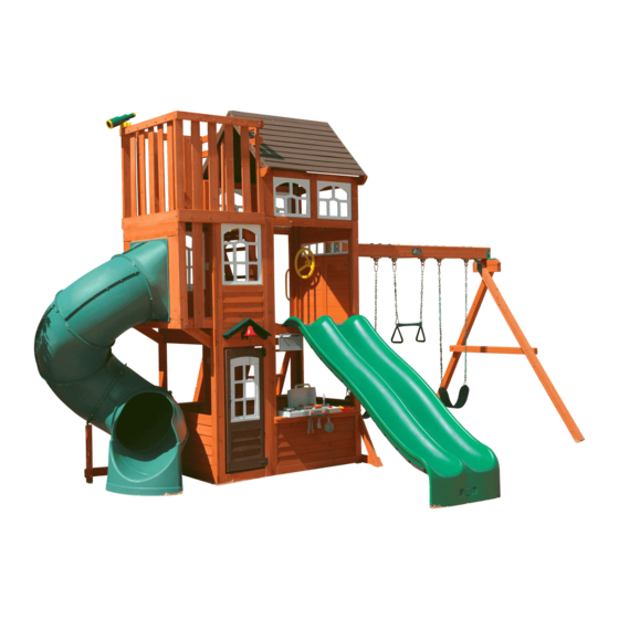
F29055 - Copper Ridge Playset Safety Zone
18' 8.6"
574cm
5.705 m
11' 7.56"
3.545 m
32' 6"
974cm
9.9 m
10 - 12 Hrs
10 - 12 Hrs
2-4 Hrs
1 - 2 Hrs
FOR FORT & SWING
FOR FORT & SWING
TUBE SLIDE
TWO PERSON
ASSEMBLY
WARNING
Manufacturer contact information provided below.
OBSTACLE FREE SAFETY ZONE - 32' 6" x 27'11" (9.9 x 8.51 m) area requires Protective Surfacing. See page 3.
27' 11"
851cm
8.51 m
MAXIMUM VERTICAL FALL HEIGHT - 7' 8" (2.34m)
354cm
CAPACITY - 16 Users Maximum, Ages 3 to 10; Weight Limit 110 lbs. (49.9 kg) per child.
RESIDENTIAL HOME USE ONLY. Not intended for public areas such as multi-unit residences, schools, churches,
nurseries, day cares or parks.
Warning. Only for domestic use.
For Outdoor Family Domestic Use Only
Cedar Summit by KidKraft
4630 Olin Road
Dallas, TX 75244, United States
customersupport@kidkraft . c om
Online Parts Replacement:
Cedarsummitplay . c om/parts-center-warranty-claim
Customer Service:
1(800) 933-0771 or (972) 385-0100
KidKraft Netherlands BV
Olympisch Stadion 29
1076DE Amsterdam, The Netherlands
Europe Customer Service: +31 (0)20 305 8620
europecustomerservice@kidkraft . c om
EU Online Parts Replacement: parts . k idkraft . e u
To reduce the risk of serious injury or death, you must read and
follow these instructions. Keep and refer to these instructions
often and give them to any future owner of this play set.
Table of Contents
Warnings And Safe Play Instructions . . . . . . . . . . pg . 2
Protective Surfacing Guidelines . . . . . . . . . . . . . . . pg . 3
Instructions For Proper Maintenance . . . . . . . . . pg . 4
About Our Wood – Limited Warranty . . . . . . . . . pg . 5
Keys To Assembly Success . . . . . . . . . . . . . . . . . . . . pg . 6
Part ID
Step-By-Step Instructions . . . . . . . . . . . . . . . . . . .pg . 20
Installation of I . D . / Warning Plaque . . . . . .Final Step
14 - 18 Hrs
FOR FORT & SWING
TWO PERSON
ASSEMBLY
pg . 10-19
Rev 10/23/2018
Advertisement
Table of Contents

Related Manuals for KidKraft Cedar Summit COPPER RIDGE PLAYSET


Summary of Contents for KidKraft Cedar Summit COPPER RIDGE PLAYSET
- Page 1 Table of Contents For Outdoor Family Domestic Use Only Cedar Summit by KidKraft 4630 Olin Road Warnings and Safe Play Instructions . . . . . . . . . . pg . 2 Dallas, TX 75244, United States Protective Surfacing Guidelines .
- Page 2 Warnings and Safe Play Instructions CONTINUOUS ADULT SUPERVISION REQUIRED. Most serious injuries and deaths on playground equipment have occurred while children were unsupervised! Our products are designed to meet mandatory and voluntary safety standards. Complying with all warnings and recommendations in these instructions will reduce the risk of serious or fatal injury to children using this play system.
- Page 3 Protective Surfacing - Reducing Risk of Serious Head Injury From Falls. One of the most important things you can do to reduce the likelihood of serious head injuries is to install shock-absorbing protective surfacing under and around your play equipment. The protective surfacing should be applied to a depth that is suitable for the equipment height in accordance with ASTM F1292.
- Page 4 Instructions for Proper Maintenance Your Cedar Summit Play System is designed and constructed of quality materials with your child’s safety in mind. As with all outdoor products used by children, it will weather and wear. To maximize the enjoyment, safety and life of your Play Set, it is important that you, the owner, properly maintain it.
- Page 5 Such use may lead to product failure and potential injury. Any and all public use will void this warranty. Cedar Summit by KidKraft disclaims all other representations and warranties of any kind, express or implied province to province. This warranty excludes all consequential damages, however, some states do not allow the...
- Page 6 Keys to Assembly Success Tools Required • Tape Measure • #1 Phillips, #2 Robertson • Open End Wrench • 3/16” Hex Key • Carpenters Level and Screwdriver (1/2” & 9/16”) • 8’ Step Ladder • Carpenters Square • Ratchet with extension •...
- Page 7 Your Key To Quick Assembly SORTING WOOD PARTS INTO EACH ASSEMBLY STEP WILL SAVE TIME! Step Step Step SAVE TIME - TIP #1: Wood parts are found in Box 2, 3, 4 & 5. Open each box with wood parts and look for the Key Number stamped on the end of the wood part (see chart below).
- Page 10 Part Identification (Reduced Part Size) Part Identification (Reduced Part Size) Part Identification (Reduced Part Size) Part Identification (Reduced Part Size) 2pc. - 044 - 15.9 x 82.6 x 482.6mm - Nest Ladder Gap FSC - Box 3 - 4819234 5/8 x 3-1/4 x 19" 1pc.
- Page 11 Part Identification (Reduced Part Size) Part Identification (Reduced Part Size) Part Identification (Reduced Part Size) Part Identification (Reduced Part Size) 2pc. - 030 - 15.9 x 133.4 x 562mm - Access Rock Bottom FSC - Box 3 - 4818515 5/8 x 5-1/4 x 22-1/8" 3pc.
- Page 12 Part Identification (Reduced Part Size) Part Identification (Reduced Part Size) Part Identification (Reduced Part Size) Part Identification (Reduced Part Size) 1pc. - 231 - 23.8 x 133.4 x 889mm - Crowsnest Bottom Side Back FSC - Box 2 - 4819306 15/16 x 5-1/4 x 35"...
- Page 13 Part Identification (Reduced Part Size) Part Identification (Reduced Part Size) Part Identification (Reduced Part Size) Part Identification (Reduced Part Size) 2pc. - 321 - 31.8 x 63.5 x 1124mm - TB Support FSC - Box 2 - 4819114 1-1/4 x 2-1/2 x 44-1/4" 2pc.
- Page 14 Part Identification (Reduced Part Size) Part Identification (Reduced Part Size) Part Identification (Reduced Part Size) Part Identification (Reduced Part Size) 2pc. - 262 - 31.8 x 128 x 684.3mm - Crowsnest Front Spacer FSC - Box 2 - 4819293 1-1/4 x 5-1/32 x 26-15/16" 1pc.
- Page 15 Part Identification (Reduced Part Size) Part Identification (Reduced Part Size) Part Identification (Reduced Part Size) Part Identification (Reduced Part Size) 1pc. - 073 - 31.8 x 1092.2 x 2336.8mm 1pc. - 072 - 31.8 x 1092.2 x 2336.8mm Wall Back Panel FSC - Box 2 - 47819203 Panel Front Wall FSC - Box 2 - 47819135 1-1/4 x 43 x 92"...
- Page 16 Part Identification (Reduced Part Size) Part Identification (Reduced Part Size) Part Identification (Reduced Part Size) Part Identification (Reduced Part Size) 1pc. - 061 - 31.8 x 514.4 x 809.6mm End Half Wall FSC - Box 3 - 47819201 1-1/4 x 20-1/4 x 31-7/8" 1pc.
- Page 17 Part Identification (Reduced Part Size) 1x - Rocks (8pk) (3320013) 1x - Cedar Summit/KidKraft 31x - Square Nylok Nut Plaque 2x - TNR 4 Post Mount (54902200) (9320358) Clamp (9200157) 1x - TNR 4 Post Mount Base (9200156) 1x - 1/4 x 14.5mm Pan 30x - 1/4 x 12.7mm Pan...
- Page 18 Hardware Identification (Actual Size) (18) FW0 - 3/16" Flat Washer - (8) FW6 - #12 Screw Bezel - (9299500) (10) LW2 - 5/16" Lock Washer - (51303300) (51103100) (58) LW1 - 1/4" Lock Washer - (51303200) (52) FW1 - 1/4" Flat Washer - (51103200) (40) TN1 - 1/4"...
- Page 19 Hardware Identification (Actual Size) Wafer Bolt 5/16 x 3" (7) WB7 - - (53613330) Wafe Bolt 5/16 x 2-1/8" (6) WB9 - - (53613324) Wafer Bolt 5/16 x 2-3/8" (2) WB8 - - (53613326) 1/4 x 1-3/8" (8) WL3 - Wafer Lag (52613216) Wafer Bolt 5/16 x 2-5/8"...
- Page 20 Europe Customer Service: +31 (0)20 305 8620 Online Parts Replacement: europecustomerservice@kidkraft.com Cedarsummitplay.com/parts-center- EU Online Parts Replacement: parts.kidkraft.eu warranty-claim Customer Service: 1(800) 933-0771 or (972) 385-0100 Read the assembly manual completely, paying special attention to EN71 and ASTM warnings; notes; and safety/maintenance information on pages 1 - 6.
- Page 21 Step 2: Access Ladder / Rockwall Assembly Part 1 A: Place (020) Right Access on one side of 4 (022) Treads and (021) Left Access on the other side with the grooves facing in. (fig. 2.1) B: Fit each (022) Tread into grooves on both (020) and (021) Access rails, make sure the top edge of the (022) Treads are flush to the front of the Access rails.
- Page 22 Step 2: Access Ladder / Rockwall Assembly Part 2 D: Place (023) Ladder Gap on each access rail so there is a 2-3/8” gap between (023) Ladder Gap and the top (022) Tread. Attach using 4 (S20) #8 x 1-3/8” Wood Screws. (fig. 2.3) E: Place (024) Rock Rail on the ground next to (020) Right Access so it matches the orientation of the two access rails as shown in fig.
- Page 23 Step 3: Rockwall Assembly A: Place (031) Access Board flush to the top of the Access Ladder/Rockwall Assembly and (030) Access Rock Bottom at the bottom of the assembly as shown in fig. 3.1. Then place (032) Board Rock A’s, (033) Board Rock B’s and (030) Access Board as they are shown in fig.
- Page 24 Step 4: Nest Ladder Assembly A: Place (042) Nest Left Access on one side of 3 (043 ) Treads and (041) Nest Right Access on the other side with the grooves facing in. (fig. 4.1) B: Fit each (043) Nest Tread into grooves on both ( 041) and (042) Nest Access Rails, make sure the top edge of Nest Access Ladder the ( 043) Treads are flush to the front of the Access rails.
- Page 25 Step 5: Nest Joist Assembly A: Place (051) Nest Joist Mid between (052) Front Wall Tie and (053) Back Wall Tie as shown in fig. 5.1 making sure to closely follow the hole orientation. Attach using 4 (S3) #8 x 2-1/2” Wood Screws. B: Using the next set of pre-drilled holes on the (053) Back Wall Tie attach the (054) Nest Joist Back using 2 (S3) #8 x 2-1/2”...
- Page 26 Step 6: Slide Wall Assembly Part 1 A: Place 1 Flange 20 on each side of the End Half Wall making sure that the panel is slat side up. Check to ensure that flanges are flush at the top and bottom and attach each flange using 3 (S40) #6 x 3/4” Truss Screws per side.
- Page 27 Step 6: Slide Wall Assembly Part 2 A: Place (062) Narrow Panel Back against the left side of (060) End Panel noticing panel orientation. The tops and bottoms of the panels should be flush and panels square. Pre-drill with a 3/16” drill bit, then fasten (062) Narrow Panel Back to (060) End Panel with 4 (WL5) 1/4 x 2-1/2”...
- Page 28 Step 7: Swing Wall Assembly A: Place (072) Panel Front Wall against the left side of (071) SW Wall Panel noticing panel orientation. The tops and bottoms of the panels should be flush and panels square. Pre-drill with a 3/16” drill bit, then fasten (072) Panel Front Wall to (071) SW Wall Panel with 4 (WL5) 1/4 x 2-1/2”...
- Page 29 Step 8: Join Swing and Slide Assemblies Part 1 A: With at least two helpers lift the Slide Wall Assembly and Swing Wall Assembly so the (062) Narrow Panel Back and (063) Narrow Front Panel meet with (073) Wall Panel Back and (072) Panel Front Wall and are tight together as shown in fig.
- Page 30 Step 8: Join Swing and Slide Assemblies Part 2 C: From inside the assembly, tight to both (072) Front Wall Panel and (063) Narrow Front Panel, halfway up the assembly, 5/8” below the panel, loosely attach 1 (082) Side Joist to (072) Front Wall Panel and (063) Narrow Front Panel Back with 3 (WB10) 5/16 x 2-5/8”...
- Page 31 Step 9: Nest Joist Assembly A: From inside the assembly measure 5/8” (15.9mm) Fig. 9.1 down from the top of the Wall Panels and place the joist assembly so that the (052) Front Wall Tie and (053) Back Wall Tie are tight to (071) Swing Wall Hidden Panel as shown in fig.
- Page 32 Step 10: Install Brackets A: On the inside of the assembly attach (062) Narrow Panel Back to (073) Wall Panel Back using 2 Flat Panel Brackets in the places shown with 4 (S8) #12 x 3/4” Pan Screws per bracket. (fig. 10.1 and 10.2) B: Repeat Step G to attach (073) Narrow Front Panel to (072) Front Wall Panel.
- Page 33 Step 11: Floor Assembly Part 1 A: Place 1 (111) Floor Board tight to (060) End Panel and 1 tight to (071) SW Wall Panel then attach each to the (082) Side Joists with 4 (S20) #8 x 1-3/8” Wood Screws per board. (fig. 11.1, 11.2 and 11.3) B: Place (112) Long Floor Joist tight to the bottom of each (111) Floor Board, centred over the pilot holes on the (060)End Panel and (071) SW Wall Panel then attach with 2 (S4) #8 x 3”...
- Page 34 Step 11: Floor Assembly Part 2 C: Measure the distance from the Back Wall to the Front Wall from the inside of the panels to make sure it equals 35-3/4”. Maintain this measurement when installing the floor boards. Starting at the Slide Wall place 3 (111) Floor Boards tight to the previously attached (111) Floor Board, followed by 1 (113) Floor Board then 8 more (111) Floor Boards.
- Page 35 Step 12: Attach Wall Tops A: In the opening of (071) SW Wall Panel, from the inside, attach (121) SW Wall Top, tight to the corner of the panels with overhang facing in with 1 (S11) #8 x 2” Wood Screw at each end as shown in fig. 12.1 and 12.2. B: In the opening of (073) Wall Back Panel, from the inside, attach (122) Half Wall Top, tight to the corner of the panels with overhang facing in with 1 (S11) #8 x 2”...
- Page 36 Step 13: Front Wall Assembly Part 1 A: Center (131) Table Support so that it’s flush to the notches in (132) Table Top as shown in fig. 13.1. Attach using 4 (S7) #12 x 2” Pan Screws as shown in fig. 13.1. B: Place Table Top Assembly in the center of opening and tight to (072) Front Wall Panel and attach (131) Table Support to (072) Front Wall Panel with 2 (S3) #8 x 2-1/2”...
- Page 37 Step 13: Front Wall Assembly Part 2 C: From inside the assembly attach (132) Table Top to slats in (072) Front Wall Panel with 2 Flat Brackets using 3 (S0) #8 x 7/8” Truss Screws per bracket. (fig. 13.4) Fig. 13.4 Inside View Table Top Assembly...
- Page 38 Step 14: Attach Diagonal A: Loosely attach (141) SW Ground to (142) Diagonal with 1 (WB9) 5/16 x 2-1/8” Wafer Bolt (with flat washer and t-nut) then place (142) Diagonal tight and flush to the front of (071) SW Wall Panel. (141) SW Ground to be flush to the bottom of (071) SW Wall Panel.
- Page 39 Step 15: Attach Access Ladder/Rockwall Assembly Part 1 A: Place Access Ladder/Rockwall Assembly from Step 3 against (073) Wall Panel Back. Line up the pre-drilled holes in the (073) Wall Panel Back making sure that it’s flush to the top of the floor boards then attach with 3 (WB9) 5/16 x 2-1/8”...
- Page 40 Step 15: Attach Access Ladder/Rockwall Assembly Part 2 B: Place (031) Access Board from Step 3, against (021) Left Access Rail and (020) Right Access Rail and flush to the top then attach with 4 (S20) #8 x 1-3/8” Wood Screws. (fig. 15.3 and 15.4) Fig.
- Page 41 Step 15: Attach Access Ladder/Rockwall Assembly Part 3 C: Place (151) Support Diagonal so that the angled end is flush to the front edge and to the bottom of (021) Left Access Rail. The opposite end should be tight against (071) SW Wall Panel. Attach (151) Support Diagonal to (021) Left Access Rail using pre drill 1 (S7) #12 x 2”...
- Page 42 Step 16: Door Panel Assembly Part 1 A: On the inside of (161) Door Window Panel measure 15” up from the bottom and attach Catch Plate flush to the edge using 2 (S38) #7 x 1-1/8” Pan Screws. (fig. 16.1 and 16.2) B: On the inside of (161) Door Window Panel measure 22”...
- Page 43 Step 16: Door Panel Assembly Part 2 C: On the outside of the (161) Door Window Panel attach the second Door Handle at approximately the same place as the one on the inside. Use 2 (S37) #7 x 5/8” Pan Screws. (fig. 16.3) D: Attach 2 Door Hinges on the outside of the (161) Door Window Panel on the opposite side from the Door Handle.
- Page 44 Step 16: Door Panel Assembly Part 3 E: In the opening for the door, measure 3/4” down from the top of (062) Narrow Front Panel and a maximum of 5/8” from right side of the opening as shown in fig. 16.5. Attach the remaining side of the hinges to (062) Narrow Front Panel using 3 (S37) #7 x 5/8”...
- Page 45 Step 16: Door Panel Assembly Part 4 F: In the notched out opening of (162) Door Stop attach the Magnetic Catch using 2 (S38) #7 x 1-1/8” Pan Screws. (fig. 16.7) Important: Use a hand held screw driver and DO NOT over tighten. G: On the inside of the assembly, attach (162) Door Stop to (063) Narrow Front Panel with 3 (S11) #8 x 2”...
- Page 46 (171) Engineered SW Beam as shown in fig. 17.1 and 17.4. IT IS IMPORTANT THAT THIS BOLT IS ATTACHED. IT WILL MINIMIZE CHECKING OF WOOD. D: Attach Cedar Summit by KidKraft Plaque to centre of (171) Engineered SW Beam (over top of t-nut) using 4 (S38) #7 x 1-1/8” Pan Screws. (fig. 17.5) Fig.
- Page 47 Step 17: Swing Beam Assembly Part 2 E: On the Fort End of (171) Engineered SW Beam attach 2 Heavy Flat Brackets with 2 (G21) 5/16 x 3-3/4” Hex Bolts (with 2 flat washers and 1 lock nut). (fig. 17.6 and 17.7) F: Place (172) SW Mount in between both Heavy Flat Brackets and place 1 Heavy L-Bracket against (171) Engineered SW Beam and (172) SW Mount.
- Page 48 Step 18: Swing Post Assembly Part 1 Heavy L-Bracket Note: Keep all bolts from Step 18 series loose Fig. 18.1 until start of Step 20 Bottom View A: Place (181) SW Block Angle on top of (182) Block SW and attach 2 Heavy L-Brackets on top of (181) SW Block Angle feeding 2 (G17) 3/8 x 6”...
- Page 49 Step 18: Swing Post Assembly Part 2 D: Place Swing End of (171) Engineered SW Beam in between Heavy L-Brackets assembled in Step A making sure holes are lined up then attach Swing Post Assembly to Swing Beam Assembly using 1 (G20) 3/8 x 4” Hex Bolt (with 2 flat washers and lock nut) through Heavy L-Bracket.
- Page 50 Step 18: Swing Post Assembly Part 3 F: Place (172) SW Mount flush to the top of (071) SW Wall Panel. Attach with 1 (G5) 5/16 x 4-1/2” Hex Bolt (with lock washer, flat washer and t-nut) in the bottom hole from outside the assembly and 1 (G5) 5/16 x 4-1/2” Hex Bolt (with 2 x flat washer and 1 lock nut) in the top hole from inside the assembly.
- Page 51 Step 19: Attach Cross Support Pre-drill all holes using a 3/16” drill bit before installing the lag screws. Fig. 19.1 A: To adjust for uneven ground, raise or lower the (191) Support Cross on the (183) SW Post. Make sure the Support Cross is level prior to attaching with the lag screws.
- Page 52 Step 20: Final Swing Post Assembly Pre-drill all holes using a 3/16” drill bit before installing the lag screws. Note: Tighten all bolts from Step 18 series before installing lag screws. A: Attach 1 (LS9) 5/16 x 4-3/4” Lag Screw (with flat washer) into each (183) SW Post, as shown in fig. 20.1. B: Attach 1 (LS9) 5/16 x 4-3/4”...
- Page 53 Step 21: Install Ground Stakes MOVE FORT TO FINAL LOCATION PRIOR TO STAKING FINAL LOCATION MUST BE LEVEL GROUND A: In the 5 places shown in fig. 21.1 drive the Rebar Ground Stakes 13” into the ground against (142) Diagonal, (060) End Panel, (021) Left Access Rail and both (183) SW Posts.
- Page 54 Step 22: Slide Entrance Assembly Part 1 Note: Bolt orientation must be followed closely for the following steps. Ensure assembly is square when tightening the bolts. A: Place 2 (221) Crowsnest posts flat on the ground with the notches facing down, making sure that the 3 pre- drilled holes are at the bottom end on both sides.
- Page 55 Step 22: Slide Entrance Assembly Part 2 E: At the bottom left end of the assembly place 1 (226) Crowsnest Side Joist so that it is upright against the (221) Crowsnest Post. Place (227) Crowsnest Gusset Front tight to (226) Crowsnest Side Joist as shown in fig.22.2 and secure all 3 parts using 1 (G21) 5/16 x 3-3/4”...
- Page 56 Step 23: Attach Crowsnest Sides A: Remove previously installed (H12) Hex Bolt 1/4 x 3 (with flat washer, lock washer and t-nut) from Step 9, Nest Joist Assembly. B: Place (231) Crowsnest Bottom Side Back on the outside left of the assembly so that it lines up with the bolt hole as shown in fig.23.1.
- Page 57 Step 24: Install Slide Entrance Assembly Part 1 A: With a helper, lift the slide entrance assembly into place so that the (226) Crowsnest Side Joists are flush with the top of the center board in the (060) End Panel. (fig.24.1 & 24.2). B: Attach assembly to the fort using 2 (S2) #8 x 1-1/2”...
- Page 58 Step 24: Install Slide Entrance Assembly Part 2 E: Make sure that slide entrance assembly is square and from outside the assembly install 10 (S3) #8 x 2-1/2” Wood Screws as shown in fig. 24.3. Fig. 24.3 x4 per side x1 per side Hardware...
- Page 59 Step 25: Install Nest Joists A: In the lower section of the crowsnest place (251) Short Joist so that it’s centered between and flush to the top of (222) Crowsnest Front and (060) End Panel. Attach (251) Short Joist using 4 (S3) #8 x 2-1/2” Wood Screws. (Fig.
- Page 60 Step 26: Attach Crowsnest Walls Part 1 A: Place 1 (261) Wall Board on each side of the crowsnest so that they are centered in the opening. Attach the top of the (261) Wall Board from the inside using 2 (S20) #8 x 1-3/8” Wood Screws per side and attach the bottom of the Wall Board from the outside using 2 (S20) #8 x 1-3/8”...
- Page 61 Step 26: Attach Crowsnest Walls Part 2 B: In the lower front of the crowsnest place 1 (262) Crowsnest Front Spacer on each side of the assembly so that they are flush with the (222) Crowsnest Front and the (221) Crowsnest Posts. Attach each Crowsnest Front Spacer through the pre-drilled holes on the (221) Crowsnest Posts using 3 (S4) #8 x 3”...
- Page 62 Step 27: Install Lower Crowsnest Floor A: Install (271) Crowsnest Front Gap using 6 (S20) #8 x 1-3/8” Wood Screws, making sure that the board is tight to the panel frame. (Fig. 27.1 & 27.2) B: Evenly space 2 (111) Floor boards in the remaining opening and attach each board using 6 (S20) #8 x 1-3/8” Wood Screws.
- Page 63 Step 28: Attach Nest Ladder A: Place Nest Ladder (built in Step 4) in the second level of the Clubhouse so that the top of the ladder is leaning flat against the (051) Nest Joist Mid and flush with the (055) Ladder Side Joist. (Fig. 28.1) B: Place 1 (111) Floorboard so that it’s flush to (051) Nest Joist Mid.
- Page 64 Step 29: Install Upper Floorboards Part 1 A: Place 3 (111) Floor Boards so that they are tight together and front board is flush with the Nest Ladder. Attach each board using 6 (S20) #8 x 1-3/8” Wood Screws. (fig. 29.1) B: Place (292) Crowsnest Floor Long Gap so that it’s tight to the Crowsnest Posts.
- Page 65 Step 29: Install Upper Floorboards Part 2 D: Install (294) Short Floor Gap using 4 (S20) #8 x 1-3/8” Wood Screws, making sure that it’s flush to the edge of (054) Nest Joist Back. (Fig.29.3) E: In the remaining opening, center and install (295) Short Floor using 4 (S20) #8 x 1-3/8” Wood Screws. (Fig.29.3). Fig.
- Page 66 Step 30: Roof Support Assemblies A: Attach 1 (301) Roof Support to a second (301) Roof Support at peak using 1 (S4) #8 x 3” Wood Screw. Repeat this twice so there are 2 Roof Support Assemblies. (fig. 30.1) Fig. 30.1 Repeat this step Wood Parts Hardware...
- Page 67 Step 31: Large Roof Assembly Part 1 A: Place (311) Front Roof Panel against (312) Back Roof Panel so the tops form a peak. Tight to the inside edge of the outside slats attach 1 Narrow Angle Bracket per slat with 2 (S0) #8 x 7/8” Truss Screws per bracket. (fig. 31.1) B: Attach the third Narrow Angle Bracket centred on the middle slat with 2 (S0) #8 x 7/8”...
- Page 68 Step 31: Large Roof Assembly Part 2 C: Place 1 Roof Support Assembly against one side of the roof assembly so the peaks meet and the ends of the roof supports are flush with the ends of the roof panels. Attach with 8 (S11) #8 x 2” Wood Screws. (fig. 31.3) D: Attach the second Roof Support Assembly on the opposite side, making sure that the peaks meet and the ends are flush.
- Page 69 Step 32: Transom Assembly Part 1 A: With the notches facing down tap 3 1/4” T-nuts into (321) TB Support then fit (323) Left Upright, (322) Right Upright and (324) Centre Upright into the notches so the ends and tops are flush, taking care to note board orientation.
- Page 70 Step 32: Transom Assembly Part 2 B: Place 2 MOD 5 Pane Windows in the openings and attach to (322) Right Upright, (323) Left Upright and (324) Centre Upright with 4 (S0) #8 x 7/8” Truss Screws per window. (fig. 32.2) C: Attach (325) Wall Tie flush to the top of (321) TB Support and to (324) Centre Upright with 4 (S11) #8 x 2”...
- Page 71 Step 33: Swing Top Assembly A: Attach (331) Swing Top to 2 (332) Swing Side Uprights with 2 (H3) 1/4 x 2-1/2” Hex Bolts (with lock washer, flat washer and t-nut). (fig. 33.1) Fig. 33.1 1/4” Lock Washer 1/4” Flat Washer 1/4”...
- Page 72 Step 34: Attach Wall Supports Note hole orientation for this step. A: Tight to the floor boards and tight in each corner of the (071) SW Wall Panel attach 2 (341) Wall Supports to (071) SW Wall Panel with 3 (S3) #8 x 2-1/2” Wood Screws per support. (fig. 34.1) Note hole orientation Fig.
- Page 73 Step 35: Attach Swing Top Assembly A: Tight to the top of (071) SW Wall Panel and flush to the outside of each (341) Wall Support place Swing Top Assembly then attach (341) Wall Supports to (332) Swing Side Uprights with 2 (S3) #8 x 2-1/2” Wood Screws per support.
- Page 74 Step 36: Attach Transom Assembly Part 1 A: Place 1 Transom Assembly on both (072) Front Wall Panel and (073) Back Wall Panel so they are tight to (331) Swing Top and (341) Wall Supports. From the outside attach each Transom Assembly to (341) Wall Supports with 2 (S3) #8 x 2-1/2”...
- Page 75 Step 36: Attach Transom Assembly Part 2 D: Attach the top of each MOD 5 Pane Window to each (321) TB Support with 1 (S0) #8 x 7/8” Truss Screw per window then attach bottom of windows to (072) Front Wall Panel and (073) Back Wall Panel with 2 (S0) #8 x 7/8” Truss Screws per window.
- Page 76 Step 37: Attach Swing Top Smalls Note: Refer to pg 77, fig 38.1. Use (381) Wall Posts as a guide to ensure correct placement of Swing Top Smalls. A: Flush to the inside edge of each transom assembly attach 1 (371) Swing Top Small using 2 (S3) #8 x 2-1/2” Wood Screws per side.
- Page 77 Step 38: Install Wall Posts A: On each side of the upper crowsnest place 1 (381) Wall Post so that the notch fits underneath the Swing Top Smalls, making sure that they are flush with the edges. Attach Wall Posts using 2 (S4) #8 x 2-1/2” Wood Screws per side.
- Page 78 Step 39: Install Wall Ties A: From the inside, place 1 (391) Short Wall Tie on each side of the upper crowsnest so that it’s flush with the long, inside edge of the (381) Wall Post as shown in fig. 39.1. Attach each (391) Short Wall Tie from the inside using 6 (S11) #8 x 2”...
- Page 79 Step 40: Attach Large Roof Assembly A: With 2 people on the ground and at least 1 person in the fort, lift the Large Roof Assembly up and over the Back side of the fort. Guide the Roof Assembly onto the fort so all four (301) Roof Supports sit flush to the front and outside edges of (331) Swing Top and the ( 371) Swing Top Smalls.
- Page 80 Step 41: Upper Deck Wall Assembly Part 1 A: From the outside, place 1 (411) Crowsnest Top Side across the top of the right side of the upper deck assembly making sure that pre-drilled holes are towards the bottom. From the outside, attach (411) Crowsnest Top Side to (381) Wall Post using 1 (WB9) 5/16 x 2-1/8”...
- Page 81 Step 41: Upper Deck Wall Assembly Part 2 C: On each side of the roof assembly, place 1 (412) Short Roof Tie so that it is resting flush on the (301) Roof Support and is flush to the outside edge of the (381) Wall Post. Attach each (412) Short Roof Tie to the (381) Wall Posts using 2 (S3) #8 x 2-1/2”...
- Page 82 Step 41: Upper Deck Wall Assembly Part 3 E: From inside the assembly on the left and right sides of the upper crowsnest place 4 (414) Cedar Wall boards per side. Attach the top end of the boards to (411) Crowsnest Top Sides using 1 (H1) ¼ x 1-1/2” Hex Bolts (with flat washer, lock washer and t-nut) per board and attach the bottom end of the boards using 2 (S20) #8 x 1-3/8”...
- Page 83 Step 42: Attach Angle Walls A: Remove the 2 screws on the ladder side of (054) Nest Joist Back. Do not discard. Place (420) Angle Wall A so that the bottom is over the existing holes and the top angle is towards the roof. Making sure that the board is straight attach at the bottom using 2 (S4) #8 x 3”...
- Page 84 Step 43: Attach Crow Ladder Grip A: Place Crow Ladder Grip with one end on the outside of the (041) Nest Right Access and the opposite end on the outside of the (055) Ladder Side Joist. Pre-drill holes using a 1/8” drill bit then attach using 2 (WL3) ¼...
- Page 85 Step 44: Attach Telescope A: On the top right hand corner of the upper crowsnest, attach Telescope Base on an angle with 2 (S11) #8 x 2” Wood Screws. (fig. 44.1 & 44.2) Telescope Fig. 44.1 Fig. 44.2 Hardware Other Parts #8 x 2”...
- Page 86 Step 45: Install Bell Support Assembly Part 1 A: Place (451) Bell Top on top of (452) Bell Support so the angled and back edges are flush then attach with 3 (S20) #8 x 1-3/8” Wood Screws. Repeat by attaching (453) Bell Top Right to top of (452) Bell Support. Rounded ends of (451) Bell Top and (453) Bell Top RT are at the bottom.
- Page 87 Step 45: Install Bell Support Assembly Part 2 C: Centred under the peak of the Bell Support Assembly attach Horseshoe Mount to (063) Narrow Front Panel with 4 (S0) #8 x 7/8” Truss Screws. (fig. 45.4 & 45.5) D: Thread the Steel Clapper Line through the Bolt. Slide Bell under overhang of Horseshoe Mount then insert Bolt up through Bell and Horseshoe Mount then secure with Nut.
- Page 88 Step 46: Attach Steering Wheel A: On (071) SW Wall Panel attach Steering Wheel with 1 (WB8) 5/16 x 2-3/8” Wafer Bolt (with flat washer and t-nut). (fig. 46.1 & 46.2 ) Fig. 46.1 5/16” Flat Fig. 46.2 Washer 5/16” T-Nut Steering Wheel...
- Page 89 Step 47: Assemble and Attach BBQ Kitchen Part 1 A: On (072) Front Wall place BBQ Base on (132) Table Top. Use BBQ Cooktop as a guide so there is enough room for BBQ Cooktop and 1” gap to the edge of the wall to the left of BBQ Base. Attach BBQ Base to (132) Table Top with 4 (S0) #8 x 7/8”...
- Page 90 Step 47: Assemble and Attach BBQ Kitchen Part 2 C: Slide BBQ Cooktop tight beside BBQ Base on the left and BBQ Sink Set tight on the right. Attach both BBQ Cooktop and BBQ Sink Set to (132) Tabel Top with 2 (S0) #8 x 7/8” Truss Screws each. (fig.47.5, 47.6, 47.7 and 47.8) D: Place Faucet and 2 Sink Knobs in opening of Sink and attach Sink Knobs with included hardware.
- Page 91 Step 48: Attach Utensil Shelves Part 1 A: From outside the assembly in the top of the opening of (072) Front Wall Panel, 1” in from the panel, attach 1 Utensil Shelf with 2 (S0) #8 x 7/8” Truss Screws as shown in fig. 48.1 and 48.2. B: Attach Sign to the Utensil Shelf.
- Page 92 Step 48: Attach Utensil Shelves Part 2 C: From outside the assembly, centred below the BBQ Kitchen attach 1 Utensil Shelf to (131) Table Support with 2 (S0) #8 x 7/8” Truss Screws as shown in fig. 48.4 and 48.5. D: Attach Pan, Tongs and Spatula to the Utensil Shelf.
- Page 93 Step 49: Attach Slides to Fort Note: Pre-drill all holes using a 1/8” drill bit before installing the pan screws. A: Place Slide centred in the opening of the (072) Front Wall Panel. (fig. 49.1) B: Attach slide to fort using 4 (S7) #12 x 2” Pan Screws. (fig. 49.2) Fig.
- Page 94 Step 50: Slide Section Assemblies Part 1 Note: When installing Pan Bolts make sure to look at holes so bolts go through the side with the round recess and the lock nuts go through the side with the hexagonal recess. (fig. 50.3) A: Fit 2 TNR2 Slide Elbows together and attach with 8 (PB1) 1/4 x 3/4”...
- Page 95 Step 50: Slide Section Assemblies Part 2 Note: When installing Pan Bolts make sure to look at holes so bolts go through the side with the round recess and the lock nuts go through the side with the hexagonal recess. (fig. 50.3) D: Attach TNR2 Slide Exit Top and the remaining TNR2 Slide Elbow together using 8 (PB1) 1/4 x 3/4”...
- Page 96 Step 51: Attach Flange Assembly to Fort A: With a helper place the Flange Assembly flush to the Crowsnest on the fort as shown in fig. 51.1 and 51.2, then pre-drill 1/8” pilot holes in the bottom 4 mounting locations on (223) Crowsnest Slide Top (approximate spots where circles are on figure), making sure the pre-drilled holes are a minimum of 1”...
- Page 97 Step 52: Attach Elbow Assembly to Flange Assembly Note: Keep all bolts loose until further step. A: Fit one of the Elbow Assemblies to the Flange Assembly by lining up the arrows on each assembly. Attach Elbow Assembly to Flange Assembly using 6 (PB1) ¼ x 3/4” Pan Bolts and Square Lock Nut. (fig. 52.1, 52.2 and 52.3) B: Attach one of the Elbow assemblies to another Elbow Assembly making sure to line up the arrows on each assembly.
- Page 98 Step 53: Attach TNR 3 Slide Exit to Elbow Assembly A: Insert flange of Exit Elbow Assembly (slide elbow) into the slots on TNR3 Short Exit. (fig. 53.1) B: Rotate Slide Exit and use Quadrex Driver as a guide pin so the holes are aligned and attach with 5 (PB1) 1/4 x 3/4”...
- Page 99 Step 54: Attach Exit End Assembly to Fort A: Fit the Exit End Assembly to the last Elbow Assembly by lining up the arrows on each assembly. Notice the elbow orientation. (fig. 54.1). Attach with 6 (¼ x 12.7)mm Pan Bolts and Square Lock Nuts. (fig. 54.2) Fig.
- Page 100 Step 55: Attach TNR 4 Clamp Rings A: Place 2 TNR4 Clamp Rings around each joint making sure to match the arrows with the end of the Clamp Ring as shown in (fig. 55.1 & 55.2 ). B: Connect TNR4 Clamp Rings in 2 spots using 1 (PB6) ¼ x 1” Pan Bolt (with lock nut) per side. (fig. 55.3) Note: When installing Pan Bolts make sure to look at holes so bolts go through the side with the round recess and the lock nuts go through the side with the hexagonal recess.
- Page 101 Step 56: Attach TNR 3 Slide to Fort A: On the fourth attached Elbow Assembly remove the pan bolt and nut which is facing the fort (installed in Step 50). (fig. 56.1) The bolt will no longer be needed, but keep the lock nut. B: Loosely attach TNR3 Tube Support (at the slightly bent end) to the slide seam using 1 (PB6) 1/4 x 1”...
- Page 102 Step 57: TNR Brace Assembly A: Attach (571) TNR Upright to (570) TNR Ground Brace with 1 (H8) 1/4 x 4-1/4” Hex Bolt (with lock washer, flat washer and t-nut) in the top hole. Make sure both boards are square then attach with 1 (S4) #8 x 3”...
- Page 103 Step 58: Attach Elbow Assemblies and TNR4 Slide A: Place TNR Brace centered over pilot holes of (570) TNR Ground Brace. Attach with 3 (S11) #8 x 2 Wood Screws. (fig. 58.3) B: Place 1 TNR4 Post Mount Clamp on either side of the Clamp Ring so that the bent tops clip in behind the Clamp Ring.
- Page 104 Step 59: Attach Ground Stake to TNR Upright A: In the spot shown in fig. 59.1 drive 1 Rebar Ground Stake 13” into the ground against the (570) TNR Ground Brace. Be careful not to hit the washer while hammering stake into the ground as this could cause the washer to break off.
- Page 105 Step 60: Assemble Rock Wall Part 1 A: In the locations shown in fig. 60.1, attach 1 rock to each rock board using 1 (PB2) 1/4 x 1-1/4” Pan Bolt (with lock washer, flat washer and barrel nut) and 1 (S10) #8 x 1” Pan Screw per rock. (fig. 60.1 & 60.2) The Pan Screw is placed in the hole beneath the Pan Bolt.
- Page 106 Step 60: Assemble Rock Wall Part 2 B: In the locations shown in (fig.60.6) loosely attach Kidney Rocks, Rock Johnsons and Crater Rocks with 1 (PB2) ¼ x 1-1/4” Pan Bolt (with lock washer, flat washer and barrel nut) per rock. C: Hold each rock in place and mark the hole locations for all remaining bolts.
- Page 107 Step 61: Attach Steel Hand Grips to Fort A: Measure 6” (152mm) from the top of (025) RW/AL Support on (073) Back Wall Panel in the 2 places shown below, pre-drill with a 1/8” drill bit then attach 2 Steel Hand Grips with 2 (WL3) 1/4 x 1-3/8” Wafer Lag (with flat washer) per Steel Hand Grip.
- Page 108 Step 61: Attach Steel Hand Grips to Fort Part 2 B: B: Place EN71 Hand Rail so the top is flush to the inside edge of (073) Back Wall Panel and the bottom is centred on (021) Left Access. Pre-drill holes using a 3/16” (4.8 mm) drill bit then attach EN71 Hand Rail using 2 (WL3) 1/4 x 1-3/8”...
- Page 109 Step 62: Attach Swings A: Using 1 Threaded Quick Link per rope, join 1 Swing Rope w/crimps to each side of the Swing Belt Seat. Make sure to close the Threaded Quick Link tightly using an adjustable wrench. (fig. 62.1 and 62.2) B: Using 1 Threaded Quick Link per rope, join the Acro Rope EN71 to the Acro Bar.
- Page 110 For children 3 to 10 years of age; weight limit of 110 lbs. per child. Maximum number of users, Installation & Operating Instructions; other information is available at: www.KidKraft.com Contact us at: KidKraft Dallas, TX 75244 USA 1-800-933-0771 Tracking Number:...
- Page 111 NOTES...
- Page 112 Comments: MAIL TO: Fill out your registration card online at KidKraft Netherlands BV www.cedarsummitplay.com/ Olympisch Stadion 29 registration 1076DE Amsterdam The Netherlands Cedar Summit by KidKraft would like to say Attention: Customer Service Thank You for your time and feedback.
Need help?
Do you have a question about the Cedar Summit COPPER RIDGE PLAYSET and is the answer not in the manual?
Questions and answers