Advertisement
Quick Links
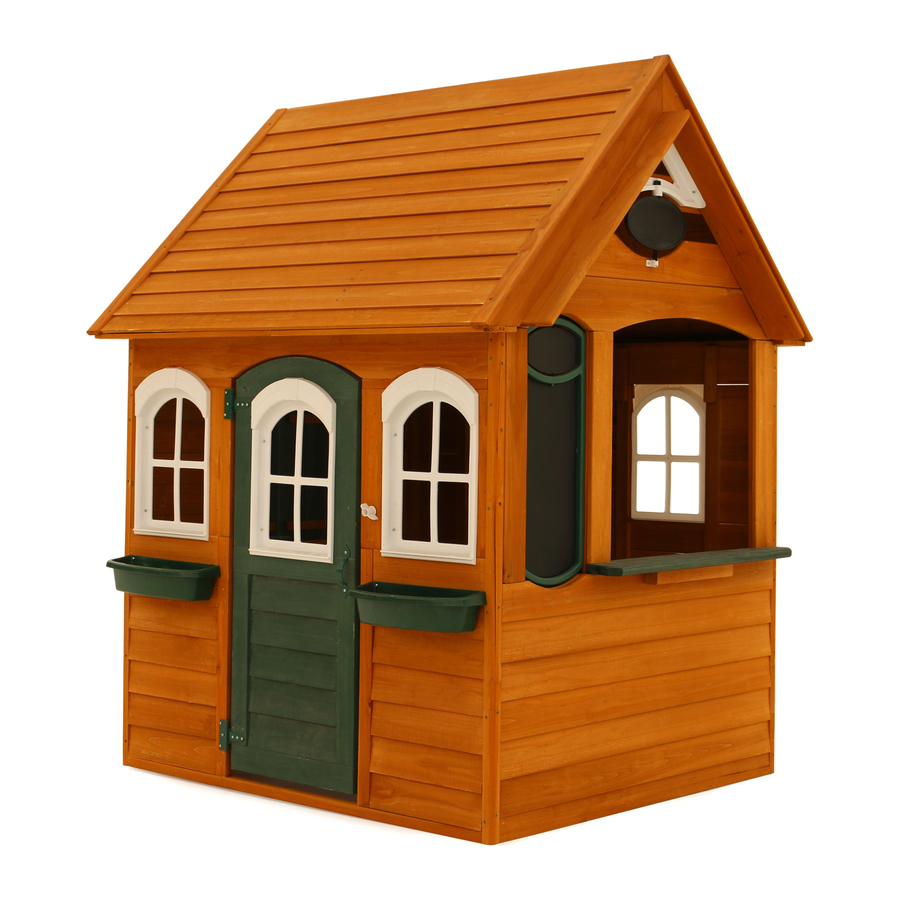
B A N C R O F T P L AY H O U S E - P 2 8 0 0 8 0 Z
INSTALLATION AND OPERATING INSTRUCTIONS
4'-8 1/4"
3 - 5 Hrs
TWO PERSON
ASSEMBLY
By
9400080
Rev 07/17/2020
WARNING
playhouse. Manufacturer contact information provided below.
CAPACITY - 3 Users Maximum, Ages 2 to 10.
4'-4 5/8"
RESIDENTIAL HOME USE ONLY. Not intended for public areas such as schools, churches,
nurseries, day cares or parks.
Cedar Summit by KidKraft
4630 Olin Road
Dallas, TX 75244, United States
customersupport@kidkraft . c om
Online Parts Replacement:
Cedarsummitplay . c om/parts-center-warranty-claim
Customer Service:
1(800) 933-0771 or (972) 385-0100
KidKraft Netherlands BV
Olympisch Stadion 29
1076DE Amsterdam, The Netherlands
Europe Customer Service: +31 (0)20 305 8620
europecustomerservice@kidkraft . c om
EU Online Parts Replacement: parts . k idkraft . e u
To reduce the risk of serious injury or death, you must
read and follow these instructions. Keep and refer to these
instructions often and give them to any future owner of this
Table of Contents
Warnings and Safe Play Instructions . . . . . . . . . . pg . 2
Instructions for Proper Maintenance . . . . . . . . . pg . 2
Keys to Assembly Success . . . . . . . . . . . . . . . . . . . . pg . 3
About Our Wood - Limited Warranty . . . . . . . . . pg . 4
Keys to Quick Assembly . . . . . . . . . . . . . . . . . . . . . . pg . 6
Part ID . . . . . . . . . . . . . . . . . . . . . . . . . . . . . . . . . . . . . . . pg . 9
Step-By-Step Instructions . . . . . . . . . . . . . . . . . . .pg . 16
Installation of I . D . / Warning Plaque . . . . . .Final Step
Advertisement

Related Manuals for KidKraft Cedar Summit Bancroft Playhouse


Summary of Contents for KidKraft Cedar Summit Bancroft Playhouse
-
Page 1: Table Of Contents
TWO PERSON ASSEMBLY Table of Contents Cedar Summit by KidKraft 4630 Olin Road Dallas, TX 75244, United States Warnings and Safe Play Instructions . . . . . . . . . . pg . 2 customersupport@kidkraft . -
Page 2: Warnings And Safe Play Instructions
Warnings and Safe Play Instructions CONTINUOUS ADULT SUPERVISION REQUIRED. Most serious injuries and deaths on playground equipment have occurred while children were unsupervised! Our products are designed to meet mandatory and voluntary safety standards. Complying with all warnings and recommendations in these instructions will reduce the risk of serious or fatal injury to children using this play system. -
Page 3: Keys To Assembly Success
Keys to Assembly Success Tools Required • Tape Measure • #1 & #2 Phillips or • Open End Wrench • Safety Glasses • Carpenters Level Robertson bits (7/16”) • Adult Helpers • Carpenters Square • Ratchet with extension • Adjustable Wrench •... -
Page 4: About Our Wood - Limited Warranty
Such use may lead to product failure and potential injury. Any and all public use will void this warranty. Cedar Summit by KidKraft disclaims all other representations and warranties of any kind, express or implied province to province. This warranty excludes all consequential damages, however, some states do not allow the... - Page 5 Battery Instruction and Warranty This device complies with Part 15 of the FCC Rules. Operation is subject to the following two conditions: (1) This device may not cause harmful interference, and (2) this device must accept any interference received, including interference that may cause undesired operation. NOTE: This equipment has been tested and found to comply with the limits for a Class B digital device, pursuant to part 15 of the FCC Rules.
-
Page 6: Keys To Quick Assembly
Your Key To Quick Assembly SORTING WOOD PARTS INTO EACH ASSEMBLY STEP WILL SAVE TIME! Step Step Step SAVE TIME - TIP #1: Open box with wood parts and look for the Key Number stamped on the end of the wood part (see chart below). Sort each wood part into the different assembly steps. -
Page 9: Part Id
Part Identification (Reduced Part Size) Part Identification (Reduced Part Size) Part Identification (Reduced Part Size) Part Identification (Reduced Part Size) 8033636 2pc. - 0336 - 10 x 25.4 x 413.8 - Window Trim - 3 (3/8 x 1 x 16‐5/16") 38037536 2pc. - 0375 - 11.9 x 76.2 x 533.7 - Cafe Side - (7/16 x 3 x 21") 38037336 1pc. - Page 10 Part Identification (Reduced Part Size) Part Identification (Reduced Part Size) Part Identification (Reduced Part Size) Part Identification (Reduced Part Size) 1pc. - 0317 - 15.9 x 108 x 958.9 - Long Cafe Gable - 3 8031736 (5/8 x 4‐1/4 x 37‐3/4") 1pc. - 0312 - 15.9 x 108 x 1168.4 - Gable Block Long - 3 8031236 (5/8 x 4‐1/4 x 46") 8pc.
- Page 11 Part Identification (Reduced Part Size) Part Identification (Reduced Part Size) Part Identification (Reduced Part Size) Part Identification (Reduced Part Size) 1pc. - 0345 - 36.5 x 63.5 x 206.5 - Window Arch Assy (Green) - 38034501 (1‐7/16 x 2‐1/2 x 8‐1/8") 2pc. - 0393 - 28.6 x 190 x 419.1 - Shutter Assy (Green) - 38039301 (1‐1/8 x 7‐1/2 x 16‐1/2") 38033536...
- Page 12 Part Identification (Reduced Part Size) Part Identification (Reduced Part Size) Part Identification (Reduced Part Size) Part Identification (Reduced Part Size) 1pc. - 0324 - 27.8 x 1016 x 1073.2 - Shutter Wall Panel - 38032436 (1‐1/8 x 40 x 42‐1/4") 1pc. - 0325 - 27.8 x 1016 x 1214.4 - Back Wall Panel - 38032536 (1‐1/8 x 40 x 47‐13/16")
- Page 13 Part Identification (Reduced Part Size) Part Identification (Reduced Part Size) Part Identification (Reduced Part Size) Part Identification (Reduced Part Size) 1pc. - 0320 - 33.7 x 920.5 x 1270 - Back Roof Panel - 38032036 (1‐5/16 x 36‐1/4 x 50") 38032136 1pc. - 0321 - 33.7 x 926.9 x 1270 - Front Roof Panel - (1‐5/16 x 36‐1/2 x 50")
- Page 14 Hardware Identification (Actual Size) #8 x 2-1/2" 8pc. S3 - Wood Screw - (52045522) #8 x 1-3/4" 16pc. S15 - Wood Screw - (52045513) #8 x 1-1/2" 92pc. S2 - Wood Screw - (52045512) #6 x 30mm 9pc. TS - Trim Screw - (52955911) #6 x 1"...
- Page 15 Part Identification (Reduced Part Size) 2x - Flower Box (Green) (9320401 ) 1x - Shutter Pivot w. hardware (4Pk) (3320790) 5x - Playhouse Window Deep (9320539) 1x - Playhouse Window Deep (White) (5Pk) 1x - Corner Bracket Set (4Pk) (3320539) (3201573) 1x - Anchored Roof Peak Spin Sign (3320508) 1x - Playhouse Plaque...
- Page 16 Europe Customer Service: +31 (0)20 305 8620 Online Parts Replacement: europecustomerservice@kidkraft.com Bigbackyard.com/parts-center-warranty/ EU Online Parts Replacement: parts.kidkraft.eu Customer Service: 1(800) 933-0771 or (972) 385-0100 Read the assembly manual completely, paying special attention to ANSI warnings; notes; and safety/maintenance information.
- Page 17 Step 2: Shutter Assembly A: Place 1 Door Handle on each (0393) Shutter Assembly centred over 1 panel as shown in fig. 2.1. Attach with 2 (S13) #6 x 5/8” Pan Screws per handle. B: On the opposite side as the Door Handles attach 2 Shutter Pivots to each (0393) Shutter Assembly using provided hardware, as shown in fig.
- Page 18 Step 3: Roof Assembly Part 1 A: Attach 1 (0316) Roof Side to another flush at the peak using 2 (S3) #8 x 2-1/2” Wood Screws. Do this twice so you have 2 Roof Support Assemblies. (fig. 3.1) Fig. 3.1 0316 Wood Parts Hardware...
- Page 19 Step 3: Roof Assembly Part 2 B: Place (0320) Back Roof Panel and (0321) Front Roof Panel on each of the Roof Support Assemblies so the Joist Sides of the Roof Panels are flush to the bottoms of each (0316) Roof Side. (fig. 3.2 and 3.3) The (0321) Front Roof Panel must overlap the (0320) Back Roof Panel and connect tightly.
- Page 20 Step 3: Roof Assembly Part 3 D: From underneath the Roof Assembly centre 1 Corner Bracket on each Joist and attach with 3 (S13) #6 x 5/8” Pan Screws per bracket as shown in fig. 3.5 and 3.6. View from Underneath Fig.
- Page 21 Step 3: Roof Assembly Part 4 E: Tight to the Roof Panels attach 1 (0330) Top Roof Side Left and 1 (0337) Top Roof Side Right to each Roof Support Assembly with 4 (S2) #8 x 1-1/2” Wood Screws per board so the peaks are tight and the bottom of each board is flush to the bottom of each Roof Panel.
- Page 22 Step 4: Front Wall Assembly A: Place (0372) Top Front Panel on top of (0322) Front Left Wall and (0575) Right Front Wall so the ends are flush. Attach from the opening in the Front Left and Right Walls with 2 (S26) #8 x 2” Pan Screws. (fig. 4.1) B: Place (0371) Front Bottom to the bottom of (0322) Front Left Wall and (0575) Right Front Wall so the ends are flush with the outside edge of each Wall and attach with 4 (S15) #8 x 1-3/4”...
- Page 23 Step 5: Window Wall Assembly A: Place (0324) Shutter Wall Panel tight to (0369) Corner Trim on (0322) Front Left Wall so the inside board is flush to the inside edge of (0369) Corner Trim. Attach (0369) Corner Trim to (0324) Shutter Wall Panel with 5 (S26) #8 x 2”...
- Page 24 Step 6: Back Wall Assembly A: Place (0325) Back Wall Panel tight to (0369) Corner Trim on (0324) Shutter Wall Panel so the inside board is flush to the inside edge of (0369) Corner Trim. Attach (0369) Corner Trim to (0325) Back Wall Panel with 5 (S26) #8 x 2”...
- Page 25 Step 7: Half Wall Assembly A: Place (0335) Half Wall Panel between (0575) Right Front Wall and (0325) Back Wall Panel so the inside edges are flush to the inside edges of both (0369) Corner Trims. Attach (0335) Half Wall Panel to both (0369) Corner Trims with 3 (S26) #8 x 2”...
- Page 26 Step 8: Soffit Assembly A: Mark the centre point of both (0372) Top Front Panel and (0370) Top Back Panel. (fig. 8.1) B: Place 2 (0376) Soffit Wides tight together on top of (0372) Top Front Panel so the inside edges line up with the marked out spot from Step A.
- Page 27 Step 9: Attach Roof to Assembly Make sure assembly is square before proceeding in this Step. A: With an adult helper lift the Roof Assembly from Step 3 onto the (0376) Soffit Wides so the tips of the (0316) Roof Sides are flush to the ends of each (0376) Soffit Wide. (fig. 9.1 and 9.2) B: Attach (0376) Soffit Wides to Roof Assembly with 3 (S2) #8 x 1-1/2”...
- Page 28 Step 10: Attach Cafe Top A: On the Half Wall Side place (0377) Cafe Top tight to top of (0376) Soffit Wides and attach to (0316) Roof Sides with 4 (S2) #8 x 1-1/2” Wood Screws. (fig. 10.1) 0316 Fig. 10.1 Note: Orientation of board.
- Page 29 Step 11: Cafe Gable Assembly Part 1 A: From inside the assembly place (0317) Long Cafe Gable tight to top of (0377) Cafe Top with arch facing up then attach to (0316) Roof Sides with 4 (S2) #8 x 1-1/2” Wood Screws. (fig. 11.1 and 11.2) B: Measure 2-3/4”...
- Page 30 Step 11: Upper Half Wall Assembly Part 2 C: From inside the assembly place 3 (0315) Chalkwall Supports as shown in fig. 11.3, making sure the notched out ends fit around the supports on the inside of (0335) Half Wall Panel. The distance between the 2 closest boards should be maintained at 9-1/4”.
- Page 31 Step 12: Window Wall Gable Assembly Part 1 A: Place Small Gable Vent between the 2 (0316) Roof Sides on the Window Wall tight to the peak. From inside the assembly attach Small Gable Vent to (0316) Roof Sides with 4 (S13) #6 x 5/8” Pan Screws. (fig. 12.1 and 12.2) Note 6 screws are shown in fig.
- Page 32 Step 12: Window Wall Gable Assembly Part 2 B: Tight to both (0316) Roof Sides place (0313) Roof Gable Support and attach to both (0316) Roof Sides with 2 (S2) #8 x 1-1/2” Wood Screws. (fig 12.3 and 12.4) C: From inside the assembly attach Small Gable Vent to (0313) Roof Gable Support with 2 (S13) #6 x 5/8 Pan Screws.
- Page 33 Step 12: Window Wall Gable Assembly Part 3 D: Tight to the top of (0374) Top Side Panel place (0312) Gable Block Long and attach to both (0316) Roof Sides with 4 (S2) #8 x 1-1/2” Wood Screws. (fig 12.6) E: Tight to the top of (0312) Gable Block Long place (0378) Gable Block and attach to both (0316) Roof Sides with 4 (S2) #8 x 1-1/2”...
- Page 34 Step 13: Window Wall Shutter Assembly Part 1 A: Centre (0397) Shutter Top over opening in (0324) Shutter Wall Panel, flush to the bottom of (0374) Top Side Panel, then place (0345) Window Arch Assembly centred on top of (0397) Shutter Top. (fig. 13.1 and 13.2) B: From inside the assembly attach (0374) Top Side Panel to (0345) Window Arch Assembly and (0324) Shutter Wall Panel to (0397) Shutter Top with 4 (S15) #8 x 1-3/4”...
- Page 35 Step 13: Window Wall Shutter Assembly Part 2 C: Insert the bottom Shutter Pivots in the 2 (0393) Shutter Assemblies from Step 2 into (0396) Shutter Bottom. (fig. 13.5 and 13.6) D: Tilt assembly and lift up to insert top Shutter Pivots into (0397) Shutter Top. Make sure it is snug. (fig. 13.6 and 13.7) E: Make sure (0396) Shutter Bottom is square to (0397) Shutter Top then from inside the assembly attach (0396) Shutter Bottom to (0324) Shutter Wall Panel with 2 (S15) #8 x 1-3/4”...
- Page 36 Step 13: Window Wall Shutter Assembly Part 3 F: Attach 1 (0336) Window Trim to each side of the opening in (0324) Shutter Wall Panel using 3 (TS) #6 x 30 mm Trim Screws per board. Notice the pilot holes are towards the inside of the assembly. (fig. 13.9 and 13.10) G: Place (0333) Shutter Stop tight to top of (0396) Shutter Bottom and tight to the panel then attach to (0396) Shutter Bottom using 3 (TS) #6 x 30 mm Trim Screws.
- Page 37 Step 13: Window Wall Shutter Assembly Part 4 H: Attach 4 (0318) Tie Blocks flush to top of (0370) Top Back Panel and to (0325) Back Wall Panel in the places shown in fig. 13.11 using 2 (S2) #8 x 1-1/2” Wood Screws per (0318) Tie Block. I: Attach 2 (0318) Tie Blocks flush to top of (0374) Top Side Panel and to (0324) Shutter Wall Panel in the places shown in fig.
- Page 38 Step 14: Door Assembly Part 1 A: On the outside of (0329) Door Panel attach 2 Door Hinges using 3 (S13) # 6 x 5/8” Pan Screws per Hinge. Judge spacing based on fig. 14.1. B: On the outside of (0329) Door Panel attach 1 Door Handle as shown in fig. 14.1, using 2 (S13) #6 x 5/8” Pan Screws.
- Page 39 Step 14: Door Assembly Part 2 E: In the opening for the door on the Front Wall, measure 5/8” up from the top of (0371) Front Bottom then attach remaining side of the Door Hinges on (0329) Door Panel to (0322) Front Left Wall with 3 (S13) #6 x 5/8” Pan Screws per hinge.
- Page 40 Step 14: Door Assembly Part 3 F: In the notched out opening of (0319) Door Latch Block attach the Magnetic Catch using 2 (S18) #6 x 1” Wood Screws. (fig. 14.5) Important: Use a hand held screw driver and DO NOT over tighten. G: From inside the assembly measure 15-1/8”...
- Page 41 Step 15: Attach Windows A: Place 1 Playhouse Window in each window opening on the Front and Back Walls as well as in the (0329) Door Panel. There should be 5 Playhouse Windows in total. Attach with 4 (S13) #6 x 5/8” Pan Screws per Playhouse Window.
- Page 42 Step 16: Attach Flower Boxes A: Place 1 Flower Box under each window opening on (0322) Front Left Wall and (0575) Right Front Wall and attach with 2 (S13) #6 x 5/8” Pan Screws per Flower Box. (fig. 16.1 and 16.2) Fig.
- Page 43 Step 17: Cafe Gable Assembly Part 1 A: From outside of the assembly place 1 (0332) Cafe Roof flush to the inside edge of (0316) Roof Side with the angled edge at the top. Top of board should align with the peak of the Roof Assembly. Attach (0332) Cafe Roof to (0316) Roof Side with 3 (S2) #8 x 1-1/2”...
- Page 44 Step 17: Upper Half Wall Assembly Part 2 D: Place (0390) Cafe Table Top between 2 (0315) Chalkwall Supports so the grooves are tight to each support as shown in fig. 17.5, 17.6 and 17.7. Attach with 2 (S3) #8 x 2-1/2” Wood Screws per (0315) Chalkwall Support. E: On the outside of the assembly centre (0620) SL Brace on the underside of (0390) Cafe Table Top so it lines up with the pilot holes on (0335) Half Wall Panel.
- Page 45 Step 17: Upper Half Wall Assembly Part 3 F: From outside of the assembly place 2 (0375) Cafe Sides over the 2 (0315) Chalkwall Supports that surround the (0390) Cafe Table Top so the edges are flush to each other. Each (0375) Cafe Side should fit tight to both (0377) Cafe Top and (0390) Cafe Table Top.
- Page 46 Step 18: Cafe Gable Assembly A: Insert Roof Peak Spinner into slot of Roof Peak Mount (fig. 18.1) and place Roof Peak Mount in opening above (0314) Short Cafe Gable tight to the peak and flush to the bottom of (0314) Short Cafe Gable. From inside the assembly attach Roof Peak Mount to (0332) Cafe Roof with 4 (S13) #6 x 5/8”...
- Page 47 Step 19: Attach Spin Chalk Sign Part 1 A: Place (0366) Spin Trim Bottom on (0335) Half Wall Panel, between both (0315) Chalkwall Supports, so the arches are flush then attach with 2 (S18) #6 x 1” Wood Screws. (fig. 19.1 and 19.2) B: Place (0367) Spin Trim Top on (0377) Cafe Top, between both (0315) Chalkwall Supports, so the arches are flush then attach with 2 (S18) #6 x 1”...
- Page 48 Step 19: Attach Spin Chalk Sign Part 2 C: Place Spin Chalk Sign between (0315) Chalkwall Supports and attach with 6 (S13) #6 x 5/8” Pan Screws. (fig. 19.3, 19.4 and 19.5) Fig. 19.3 Spin Chalk Sign Fig. 19.4 Parts removed for clarity. 0315 Outside View Fig.
- Page 49 Step 20: Attach Door Bell Assembly Note: Install 2 AAA/LR03 batteries in Doorbell 2 prior to attaching to assembly. To replace batteries remove back cover on Doorbell 2, remove both batteries, insert 2 new batteries ensuring the proper polarity is observed then replace back cover. A: From inside the assembly attach Doorbell to (0575) Right Front Wall with 2 (S10) #8 x 1”...
- Page 50 Step 21: Attach Playhouse Plaque A: From outside the Playhouse attach Playhouse Plaque to (0316) Roof Sides with 2 (S13) #6 x 5/8” Pan Screws as shown in fig. 21.1 and 21.2 0316 Fig. 21.1 Outside View 0316 Playhouse Plaque Fig.
- Page 51 NOTES...
- Page 52 Would you recommend the purchase of our products to friends and family? Comments: MAIL TO: Fill out your registration card online at KidKraft www.cedarsummitplay.com/ 4630 Olin Road registration Dallas, TX 75244 United States Cedar Summit by KidKraft would like to say Attention: Customer Service Thank You for your time and feedback.
Need help?
Do you have a question about the Cedar Summit Bancroft Playhouse and is the answer not in the manual?
Questions and answers