Table of Contents
Advertisement
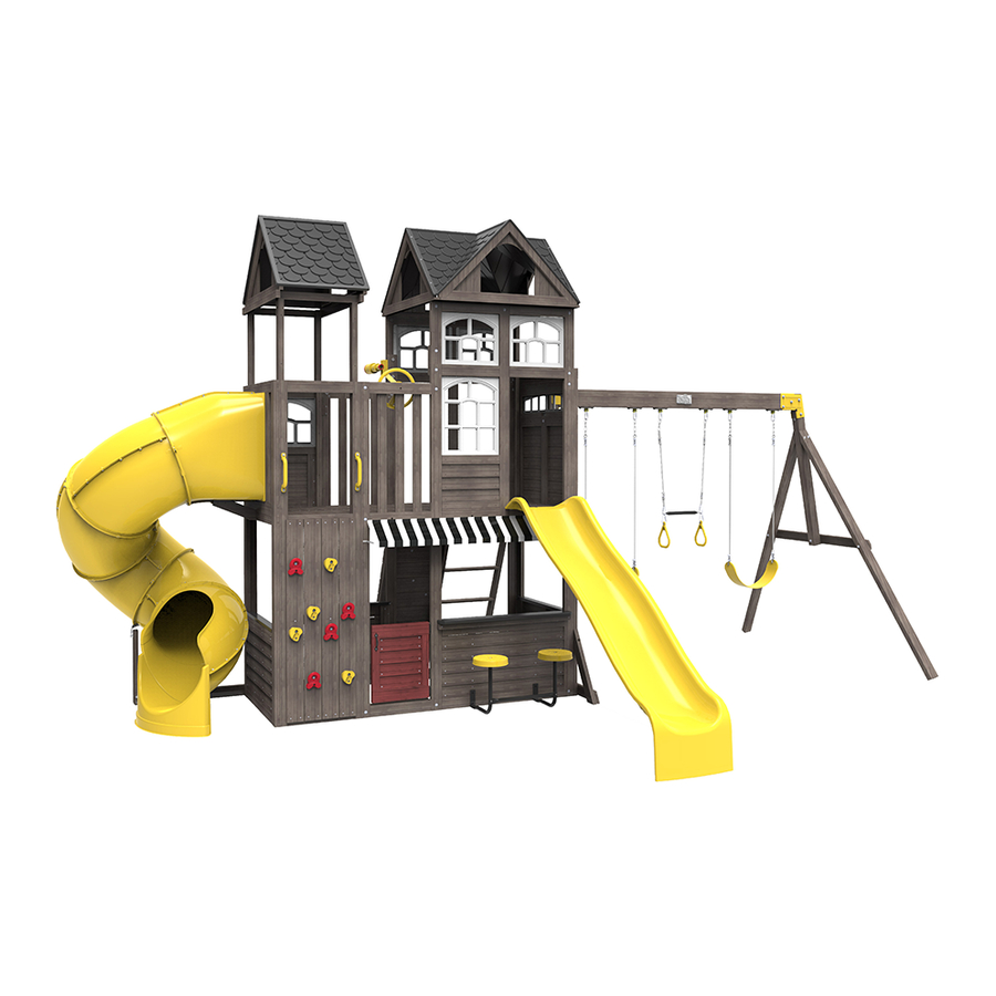
DEVONSHIRE ELITE PLAYSET FSC - F29365
INSTALLATION AND OPERATING INSTRUCTIONS
WARNING
owner of this play set. Manufacturer contact information provided below.
OBSTACLE FREE SAFETY ZONE -
See page 3.
MAXIMUM VERTICAL FALL HEIGHT - 6' 8.8" (2.052m)
CAPACITY - 17 Users Maximum, Ages 3 to 10; Weight Limit 110 lbs. (49.9 kg) per child.
RESIDENTIAL HOME USE ONLY. Not intended for public areas such as multi-unit residences,
schools, churches, nurseries, day cares or parks.
Warning. Only for domestic use.
To reduce the risk of serious injury or death, you must
read and follow these instructions. Keep and refer to
these instructions often and give them to any future
area requires Protective Surfacing.
33' 2" x 22' 5.7" (10.11 x 7.46 m)
Obstacle Free Safety Zone
Maximum Number of Users: 17
Cedar Summit by KidKraft
4630 Olin Road
Dallas, TX 75244, United States
customerservice@kidkraft.com
Online Parts Replacement: parts.kidkraft.com
To warranty your product: kidkraft.com/warranty/
Customer Service:
1(800) 933-0771 or (972) 385-0100
KidKraft Netherlands BV
Olympisch Stadion 8
1076 DE Amsterdam, The Netherlands
Europe Customer Service: +31 (0)20 305 8620
europecustomerservice@kidkraft.com
EU Online Parts Replacement: parts.kidkraft.eu
10 - 20 Hrs
FOR FORT & SWING
TWO PERSON
ASSEMBLY
33' 2"
10 .11 m
240 .43"
6 .11 m
F29005
Table of Contents
Warnings And Safe Play Instructions . . . . . pg . 2
Protective Surfacing Guidelines . . . . . . . . . pg . 3
Instructions For Proper Maintenance . . . . . . pg . 4
About Our Wood – Limited Warranty . . . . . pg . 5
Keys To Assembly Success . . . . . . . . . . . . . pg . 7
Part ID . . . . . . . . . . . . . . . . . . . . . . . . . . .pg . 8-17
Step-By-Step Instructions . . . . . . . . . . pg . 18-98
Installation of I .D ./Warning Plaque . . . Final Step
9409365
10 - 12 Hrs
10 - 12 Hrs
2-4 Hrs
2 - 4 Hrs
FOR FORT & SWING
FOR FORT & SWING
TUBE SLIDE
TWO PERSON
ASSEMBLY
33'5 17/64"
1019.22
cm
20'3 25/32"
619.22
cm
22' 5 .7"
28'1 15/64"
136 .12"
7 .46 m
856.56
3 .46 m
11'6 21/64"
351.35
cm
128 .75"
10'11 1/16"
3 .27 m
332.90
Rev 10/20/2020
cm
Advertisement
Table of Contents

Related Manuals for KidKraft Cedar Summit DEVONSHIRE ELITE


Summary of Contents for KidKraft Cedar Summit DEVONSHIRE ELITE
- Page 1 Protective Surfacing Guidelines . . . . . . . . . pg . 3 To warranty your product: kidkraft.com/warranty/ Instructions for Proper Maintenance . . . . . . pg . 4...
- Page 2 Warnings and Safe Play Instructions CONTINUOUS ADULT SUPERVISION REQUIRED. Most serious injuries and deaths on playground equipment have occurred while children were unsupervised! Our products are designed to meet mandatory and voluntary safety standards. Complying with all warnings and recommendations in these instructions will reduce the risk of serious or fatal injury to children using this play system.
- Page 3 Protective Surfacing - Reducing Risk of Serious Head Injury From Falls One of the most important things you can do to reduce the likelihood of serious head injuries is to install shock-absorbing protective surfacing under and around your play equipment. The protective surfacing should be applied to a depth that is suitable for the equipment height in accordance with ASTM F1292.
- Page 4 Instructions for Proper Maintenance Your KidKraft Play System is designed and constructed of quality materials with your child’s safety in mind. As with all outdoor products used by children, it will weather and wear. To maximize the enjoyment, safety and life of your Play Set, it is important that you, the owner, properly maintain it.
- Page 5 About Our Wood KidKraft Premium Play Systems uses only premium playset lumber, ensuring the safest product for your children’s use . Although we take great care in selecting the best quality lumber available, wood is still a product of nature and susceptible to weathering which can change the appearance of your set .
- Page 6 KidKraft Limited Warranty MISSING OR DAMAGED PARTS: KidKraft will replace any parts within 90 days from date of purchase found to be missing from or damaged in the original packaging . See Fig .1 Fig . 1 Product Age (All Parts)
- Page 7 Keys to Assembly Success Tools Required • Tape Measure • #1 Phillips, #2 Robertson • Open End Wrench • 3/16” Hex Key • Carpenters Level and Screwdriver (1/2” & 9/16”) • 8’ Step Ladder • Carpenters Square • Ratchet with extension •...
- Page 8 Part Identification (Reduced Part Size) Part Identification (Reduced Part Size) Part Identification (Reduced Part Size) Part Identification (Reduced Part Size) 2pc . - 9351 - 15 .9 x 40 .4 x 1100 .9 - Soffit Narrow - 3139351 5/8 x 1-19/32 x 43-11/32" 5pc.
- Page 9 Part Identification (Reduced Part Size) Part Identification (Reduced Part Size) Part Identification (Reduced Part Size) Part Identification (Reduced Part Size) 1pc. - 2606 - 23 .8 x 82 .6 x 362 - SW Ground - 3132606 15/16 x 3-1/4 x 14-1/4" 4pc.
- Page 10 Part Identification (Reduced Part Size) Part Identification (Reduced Part Size) Part Identification (Reduced Part Size) Part Identification (Reduced Part Size) 1pc. - 8963 - 31 .8 x 76 .2 x 819 .2 - TNR Ground Brace - 3138963 1-1/4 x 3 x 32-1/4" 2pc.
- Page 11 Part Identification (Reduced Part Size) Part Identification (Reduced Part Size) Part Identification (Reduced Part Size) Part Identification (Reduced Part Size) 1pc. - 2615 - 76 .2 x 76 .2 x 1294 .3 - SW Upright - 3132615 3 x 3 x 50-61/64" 1pc.
- Page 12 Part Identification (Reduced Part Size) Part Identification (Reduced Part Size) Part Identification (Reduced Part Size) Part Identification (Reduced Part Size) 4pc. - 9381 - 15 .9 x 114 .3 x 1295 .4 - Vertical Rock Board - 3139381 5/8 x 4-1/2 x 51" 2pc.
- Page 13 Part Identification (Reduced Part Size) Part Identification (Reduced Part Size) Part Identification (Reduced Part Size) Part Identification (Reduced Part Size) 2pc. - 9248 - 31 .8 x 546 .1 x 2201 .3 - Narrow Panel 1pc. - 2655 - 32 .8 x 828 .6 x 377 .8 - Half Wall 37139248 1-1/4 x 21-1/2 x 86-21/32"...
- Page 14 (3310231) (Yellow) (9200015) 1x - Rocks (9 Pk) (3329000) -Yellow/Poppy 1x - Stamped Swing Hangers (3212906)(6pk) 1x - Kidkraft Logo Plaque (3320353) 1x - 1/8" Drill Bit 1x - Telescope w/ Mount 2x - Long Belt Swing (9300183) (3320261) w/ Welded Chain...
- Page 15 Part Identification (Reduced Part Size) 1X - Corner Bracket 1x - Rocks (8 Pk) (9201670) (3329005) -Yellow/Poppy 1x - Jamb Mount (3201601) (2Pk) 1x - MOD 5 Pane Window -White (9330502) 2x - Gable Roof Panel (9327750)
- Page 16 Hardware Identification (Actual Size) Wafer Bolt 5/16 x 3" Hex Bolt 1/4 x 1-1/4" 3pc. WB7 - - (53613330) 4pc. H9 - - (53703211) 6 .4 x 31 .8mm 7 .9 x 76 .2mm Wafer Bolt 5/16 x 2-5/8" 9pc. WB10 - - (53613329) Hex Bolt 1/4 x 2-1/4"...
- Page 17 Hardware Identification (Actual Size) 8pc. FW3 - #8 Flat Washer - (51003500) 17pc. TN1 - 1/4" T - Nut (54503200) 16pc. LW2 - 5/16" Lock Washer - (51303300) 6 .4mm 7 .9mm 18pc. FW0 - 3/16" Flat Washer - (51103100) 4 .8mm 35pc.
- Page 18 • The carton I .D . stamp is located on the end of each carton . The tracking number is located on the KidKraft ID Plaque (9320374) . • Please retain this information for future reference . You will need this information if you contact the Consumer Relations Department .
- Page 19 Step 2: Front Wall Assembly Part 1 Note: All bolts are installed loosely from the underside of panel assembly. A: On the ground lay flat (9368) Right Upright Front and to the right of it lay flat (9369) Left Upright Front, making sure that the notches on both boards are facing up and that they are oriented as shown in fig.
- Page 20 Step 2: Front Wall Assembly Part 2 E: Bring the top and bottom of the frame assemblies together as shown in fig. 2.3. Place 1 (9353) Cross Support Top across the assemblies where they meet . Attach (9353) Cross Support Top to (9368) Right Upright Front using 1 (WB1) 5/16 x 1”...
- Page 21 Step 2: Front Wall Assembly Part 3 H: Place 2 MOD 5 Pane Windows in the upper openings and attach to frame assembly using 7 (S0) #8 x 7/8” Truss Head Screws per window . (fig. 2.5, 2.7 and 2.8) I: Place (9377) Window Brace over the pre-drilled holes in (9353) Cross Support Top and (9369) Left Upright Front to join the sections.
- Page 22 Step 2: Front Wall Assembly Part 4 L: In the center notches of (9367) Narrow Mid Cross Front and (9451) Cross Support Middle Short place (9374) Baluster making sure that the bolt hole is at the top. Attach using 4 (S30) #8 x 1-1/16” Wood Screws. (fig 2.9 and 2 .10) M: Place 1 (9373) Baluster in each of the outside notches and attach using 4 (S30) #8 x 1- 1/16”...
- Page 23 Step 2: Front Wall Assembly Part 5 P: Place (2655A) Half Wall into the upper opening on the right side . Attach using 4 (S0) # 8 x 7/8” Truss Head Screws . (fig. 2.12 and 2.14) Q: Place 1 MOD 8 Pane Window in the upper opening and attach to frame assembly using 9 (S0) #8 x 7/8” Truss Head Screws.
- Page 24 Step 3: Back Wall Assembly Part 1 Note: All bolts are installed loosely from the underside of panel assembly. A: On the ground lay flat (9370) Right Upright Back and to the right of it lay flat (9371) Left Upright Back, making sure that the notches on both boards are facing up and that they are oriented as shown in fig.
- Page 25 Step 3: Back Wall Assembly Part 2 E: Bring the top and bottom of the frame assemblies together as shown in fig. 3.3. Place 1 (9353) Cross Support Top across the assemblies where they meet . Attach (9353) Cross Support Top to (9371) Left Upright Back using 1 (WB1) 5/16 x 1”...
- Page 26 Step 3: Back Wall Assembly Part 3 H: Place 2 MOD 5 Pane Windows in the upper openings and attach to frame assembly using 7 (S0) #8 x 7/8” Truss Head Screws per window. (fig. 3.5, 3.6 and 3.7) I: Place (9377) Window Brace over the pre-drilled holes in (9353) Cross Support Top and (9370) Right Upright Back to join the sections.
- Page 27 Step 3: Back Wall Assembly Part 4 L: Place 1 (9373) Balluster in each of the notches in (9366) Narrow Mid Cross Back and (9451) Cross Support Middle Short, making sure they are flush. Attach using 4 (S30) #8 x 1- 1/16” Wood Screws per board. (fig. 3.9 and 3 .10) M: Check to ensure that the assembly is square, then install 10 (S30) #8 x 1- 1/16”...
- Page 28 Step 3: Back Wall Assembly Part 5 O: Place (9218) Small Half Wall Insert into the bottom of the narrow opening on the left side of the assembly . Attach using 4 (S0) # 8 x 7/8” Truss Head Screws . (fig. 3.12 and 3.13) Fig.
- Page 29 Step 4: Swing Wall Assembly A: With a helper, stand Front Wall Panel upright and place (9213) SW Wall Panel against the tall end of the panel so that the edges are flush. The bottom of the panels should be flush and panels square. Pre-drill with a 3/16”...
- Page 30 Step 5: Table Top Assembly Part 1 A: Place (2612) Table Support flush to the notched out ends of (9324) Table Top and attach with 4 (S7) #12 x 2” Pan Screws as shown in fig. 5.1. B: Place Table Top Assembly in the center of opening and tight to Front Wall Panel and attach (2612) Table Support to Front Wall Panel with 2 (S3) #8 x 2-1/2”...
- Page 31 Step 5: Table Top Assembly Part 2 C: From the inside of the assembly attach (9324) Table Top to slats in Front Wall Panel with 2 Flat Brackets using 3 (S0) #8 x 7/8” Truss Head Screws per bracket. (fig. 5.4) 9324 Fig.
- Page 32 Step 6: Slide Wall Assembly A: With a helper, place 1 (9248) Narrow Panel up against the inside edge of (9214) End Slide Panel so that the edges are flush. The tops and bottoms of the panels should be flush and panels square. Predrill with a 3/16” drill bit, then fasten (9214) End Slide Panel to (9248) Narrow Panel with 4 (WL5) 1/4 x 2-1/2”...
- Page 33 Step 7: Join Swing and Slide Assemblies Part 1 A: With at least one helper, bring the 2 assemblies together so the wall panels meet tightly. Panels should be flush at the tops and bottom. (fig. 7.1) B: Place (2608) Floor Joist across the joints on each side, making sure that they are tight to the (9214) End Slide Panel.
- Page 34 Step 7: Join Swing and Slide Assemblies Part 2 C: From inside the assembly, tight to the Front Wall Panel, measure 5/8” (16mm) down from the center of the panel assembly and loosely attach 1 (9356) Side Floor Joist to Front Wall Panel using 3 (WB10) 5/16 x 2-5/8” Wafer Bolts (with flat washer and t-nut), making sure that it’s tight to the (9214) End Slide Panel.
- Page 35 Step 8: Floor Assembly Part 1 A: Place 1 (9359) Floor Board tight to (9213) SW Wall Panel and attach to the (9382) Side Joists with 4 (S20) #8 x 1-3/8” Wood Screws. (fig. 8.1) B: Have a helper hold (9356) Center Floor Joist tight to the bottom of (9359) Floor Board and centered over the pilot holes in the (9213) SW Wall Panel.
- Page 36 Step 8: Floor Assembly Part 2 F: Place 1 (9358) Floor Board A tight to (9214) End Slide Panel and attach to the (9356) Side Floor Joists with 4 (S20) #8 x 1-3/8” Wood Screws. (fig 8.3) G: Place (9461) Short Central Floor Joist so that it fits between (9214) SW End Panel and (9462) Center Floor Support and is tight to the bottom of the (9358) Floor Board A.
- Page 37 Step 8: Floor Assembly Part 3 J: Starting at the (9214) End Slide Panel side, place 3 (9358) Floor Board A’s next to the one that was previously installed. (fig 8.6) K: Place 2 (9359) Floor Boards side by side, next to the (9358) Floor Board A’s. (fig 8.6) L: Evenly space the remaining 12 (9358) Floor Board A’s.
- Page 38 Step 9: Install Window and Wall Insert Part 1 A: On the Back Wall, in the upper opening of the (9248) Narrow Panel, attach one (2655A) Half Wall from the inside using 2 (S0) #8 x 7/8” Truss screws per side. (fig 9.1 and 9.2) B: Place (9386) Window Bottom Spacer on top of (2655A) Half Wall so that it’s flush with the panel frame.
- Page 39 Step 9: Install Window and Wall Insert Part 2 C: Insert MOD 5 Pane Window into the opening and attach to (9248) Narrow Panel and (9386) Window Bottom Spacer using 7 (S0) #8 x 7/8” Truss Screws . Fig. 9.3 Fig.
- Page 40 Step 10: Attach Hand Grips to Tower Pre-drill all holes using a 1/8” drill bit before installing the Wafer Lags A: On the front (9248) Narrow Panel, measure 1” (25mm )up from the top of the floor boards and center 1 Hand Grip on each side .
- Page 41 Step 11: Attach Rockwall Part 1 A: In the front lower opening of the (9248) Narrow Panel center 1 (9386) Window Bottom Spacer ensuring that there is a measurement of 22- 7/16” (570mm) between the board and the frame at both the top and bottom . Attach (9386) Window Bottom Spacer to each side of the (9248) Narrow Panel using 2 (S4) #8 x 3”...
- Page 42 Step 11: Attach Rockwall Part 2 D: Alternating colors and shapes, attach 2 rocks to each rock board using 1 (PB2) 1/4 x 1-1/4” Pan Bolt (with lock washer, flat washer and barrel nut) and 1 (S10) #8 x 1” Pan Screw per rock. (fig. 11.3 and 11.4) The Pan Screw is placed in the hole beneath the Pan Bolt.
- Page 43 Step 12: Install Jamb Mount A: On the back wall, Measure 2” (50mm) down from the bottom of (9366) Narrow Mid Cross and place 1 Jamb Mount centered over (9363) Base End Post and (9248) Narrow Panel . Attach Jamb Mount using 4 (S0) #8 x 7/8” Truss Screws.
- Page 44 Step 13: Attach Wall Supports A: In the upper level of the unit place 1 (9460) Wall Support in each corner so that they are tight to (9214) End Slide Panel and the (9248) Narrow Panels . Attach 9460 Wall Supports to 9248 Narrow Panels using 3 (S3) #8 x 2-1/2 Wood Screws per support, making sure to note the hole orientation .
- Page 45 Step 14: Tower Roof Support Assembly Part 1 A: Place 1 (9379) Soffit across each side of the (9460) Supports as shown in fig. 14.1, making sure that they are flush with the tops of the supports. Attach using 2 (H11) 1/4 x 2- 3/4” Hex Bolts (with lock washer, flat washer and t-nut) per side.
- Page 46 Step 14: Tower Roof Support Assembly Part 2 B: Place (9459) Short Bottoms across the front and back of the tower assembly so they are flush to the tops of (9460) Wall Supports and (9379) Soffits. Attach from the outside of (9379) Soffits using 4 (S11) #8 x 2” Wood Screws per board.
- Page 47 Step 15: Gable End Assembly Part 1 A: Attach one (2852) Roof End to a second (2852) Roof End at peak using 1 (S3) #8 x 2-1/2” Wood Screw . (fig. 15.1) B: Place 1 (2853) Roof Support between the Roof Ends so the bottom of the Roof Support is flush with the bottoms of each Roof End.
- Page 48 Step 15: Gable End Assembly Part 2 D: From the peak of the gable assembly measure approximately 3” (80 .37mm) down and attach 1 (2843) Gable Board C using 4 (S20) #8 x 1-3/8” Wood Screws as shown in (fig. 15.3 and 15.4). Maintain a 1” (25.40mm) space between the sides of Gable Board C and the edge of the Gable Assembly.
- Page 49 Step 16: Tower Roof Assembly A: Line up the connector tabs on the 2 Roof Panels and snap the panels together. (fig 16.1) B: Place the Roof Panel assembly over the Gable Assembly and attach to the (2852) Roof Ends using 12 (S11) #8 x 2”...
- Page 50 Step 17: Attach Tower Roof A: With a helper, lift the roof assembly and place it onto the tower assembly so that the (2853) Roof Supports are flush to (9379) Soffits. Attach (2853) Roof Supports to (9379) Soffits using 2 (S4) #8 x 3” Wood Screws per support.
- Page 51 Step 18: Attach Wall Tops A: In the opening of (9213) SW Wall Panel, from the inside, place (9071) SW Wall Top, tight to the corner of the panels with overhang facing in. Attach using 1 (S11) #8 x 2” Wood Screw at each end as shown in fig. 18.1 and 18 .2 .
- Page 52 Step 19: Dutch Door Assembly Part 1 A: On the outside edge of the (9215) Dutch Door, measure 2 .6” (66mm) down from the top of the door and install 1 Door Handle using 2 (S37) #7 x 5/8” Pan Screws. (fig. 19.1) B: At the opposite end of the door panel, measure 0 .3”...
- Page 53 Step 19: Dutch Door Assembly Part 2 E: In the opening for the door put Dutch Door Assembly in place, measuring to ensure that it is 5/8” (15 .9mm) up from the bottom frame (fig. 19.6). Attach hinges to the Front Wall Frame using 3 (S37) #7 x 5/8” Pan Screws per hinge as shown in fig.
- Page 54 Step 19: Dutch Door Assembly Part 3 F: In the notched out opening of (1913) Door Latch Block attach the Magnetic Catch using 2 (S38) #7 x 1-1/8” Pan Screws. (fig. 19.7) Important: Use a hand held screw driver and DO NOT over tighten. Fig.
- Page 55 Step 19: Dutch Door Assembly Part 4 G: On the inside of the assembly, attach (1913) Door Latch Block to (9363) Base End Post with 2 (S11) #8 x 2” Wood Screws, making sure (1913) Door Latch Block overhangs (9363) Base End Post by 1-1/4” (32mm) and is in position to receive the Catch Plate.
- Page 56 Step 20: Access Ladder / Rockwall Assembly Part 1 A: Place (9239) Left Rail on one side of 4 (8957) Treads and (9055) Right Access on the other side with the grooves facing in. (fig. 20.1) B: Fit each (8957) Tread into grooves on both (9239) and (9055) Access rails, making sure the top edge of the (8957) Treads are flush to the front of the Access rails.
- Page 57 Step 20: Access Ladder / Rockwall Assembly Part 2 D: Place (8958) Ladder Gap on each access rail so there is a 2-3/8” (60mm) gap between (8958) Ladder Gap and the top (8957) Tread. Attach using 4 (S20) #8 x 1-3/8” Wood Screws. (fig. 20.3) E: Place (9058) Rock Rail on the ground next to (9055) Right Access so it matches the orientation of the two access rails as shown in fig.
- Page 58 Step 21: Rockwall Assembly Part 1 A: Place (9032) Access Board flush to the top of the Access Ladder/Rockwall Assembly and (8515) Access Rock Bottom at the bottom of the assembly as shown in fig. 21.1. Then place (8511) Board Rock A and (8512) Board Rock B as shown in fig.
- Page 59 Step 21: Rockwall Assembly Part 2 C: Alternating colors and shapes, attach 1 rock to each rock board using 1 (PB2) 1/4 x 1-1/4” Pan Bolt (with lock washer, flat washer and barrel nut) and 1 (S10) #8 x 1” Pan Screw per rock. (fig. 21.2 and 21.3). The Pan Screw is placed in the hole beneath the Pan Bolt.
- Page 60 Step 22: Attach Access Ladder/Rockwall Part 1 A: Place Access Ladder/Rockwall Assembly against Back Wall Panel and flush to the top of the floor boards then attach with 4 (S20) #8 x 1 -3/8” Wood Screws . (fig. 22.1 and 22.2) Fig.
- Page 61 Step 22: Attach Access Ladder/Rockwall Part 2 B: Place (9032) Access Board against (9055) Right Access and (9058) Rock Rail and flush to the top then attach with 4 (S20) #8 x 1-3/8” Wood Screws. (fig. 22.3) Fig. 22.3 9032 2-1/8”...
- Page 62 Step 22: Attach Access Ladder/Rockwall Part 3 C: Place (9269) Support Diagonal so that the angled end is flush to the front edge and to the bottom of (9239) Left Rail . The opposite end should be tight against (9360) Back Post Left . Attach (9269) Support Diagonal to (9239) Left Rail using 1 (H10) 1/4 x 2-1/4”...
- Page 63 Step 23: Attach Hand Grips to Fort A: Measure 6” (152mm) from the top of (9062) RW/AL Support on Back Wall Panel in the 2 places shown below . Pre-drill with a 1/8” drill bit then attach 2 Hand Grips using 2 (WL3) 1/4 x 1-3/8” Wafer Lag per Hand Grip .
- Page 64 Step 24: Attach Wall Supports Note: It is important to note hole orientation for this step. A: Tight to the floor boards and tight in each corner of the (9213) SW Wall Panel attach 2 (9118) Wall Supports using 7 (S3) #8 x 2-1/2” Wood Screws per support . (fig. 24.1 and 24.2) Fig.
- Page 65 Step 25: Attach Soffits A: On the top of the Front Wall place 1 (9350) Soffit so that it’s centered over (9365) TB Support and flush to the inside edge, making sure to follow the hole orientation closely. Using the inside set of holes, attach (9350) Soffit with 6 (S20) #8 x 1- 3/8”...
- Page 66 Step 26: Gable End Assembly Part 1 A: Attach one (2852) Roof End to a second (2852) Roof End at peak using 1 (S3) #8 x 2-1/2” Wood Screw . (fig. 26.1) B: Place 1 (2853) Roof Support between the Roof Ends so the bottom of the Roof Support is flush with the bottoms of each Roof End.
- Page 67 Step 26: Gable End Assembly Part 2 D: From the peak of the gable assembly measure approximately 3” (80 .37mm) down and attach 1 (2843) Gable Board C using 4 (S20) #8 x 1-3/8” Wood Screws as shown in (fig. 26.3 and 26.4). There should a 1” (25.40mm) space between the sides of Gable Board C and the edge of the Gable Assembly.
- Page 68 Step 27: Attach Roof Panels Part 1 Note: It is important to ensure that there is a 5mm square opening in the top, center of the roof. This will be used in a later step. Build 4 of these assemblies Build 4 of these assemblies A: Bend roof panel along the fold to allow the panel to fit between the gables.
- Page 69 **other gables hidden for clarity** 2X #8 x 1-1/2" WS per roof Step 27: Attach Roof Panels Begin with two gable assemblies and assemble as shown Part 2 note: this hole D: Take a second roof panel and fit the connector tabs so they are coupled with the panel that was previously not used **other gables hidden for clarity** 2X #8 x 1-1/2"...
- Page 70 Step 27: Attach Roof Panels Part 3 E: Repeat all steps to complete the roof assembly, making sure that a 5mm square opening is left in the center of the roof assembly. (fig. 27.9, 27.10 and 27.11) Fig. 27.9 continue with the other 3 assemblies leaving a 5mm square opening in the centre...
- Page 71 Step 28: Attach Roof to Fort A: With 2 people on the ground and at least 1 person in the fort, lift the Roof Assembly up and over the Back side of the fort. Guide the Roof Assembly onto the fort so all four Gable Assemblies sit flush to the front and outside edges of the (9350) Soffits and the (9351) Soffit Narrows.
- Page 72 Beam as shown in (fig. 29.2). IT IS IMPORTANT THAT THIS BOLT IS ATTACHED. IT WILL MINIMIZE CHECKING OF WOOD. C: Attach KidKraft Plaque to centre of (9452) Engineered Beam (over top of t-nut) using 4 (S18) #6 x 1” Wood Screws. (fig. 29.3) Fig.
- Page 73 Step 29: Swing Beam Assembly Part 2 D: On the Fort End of (9452) Engineered SW Beam attach 2 Heavy Flat Brackets with 2 (G21) 5/16 x 3-3/4” Hex Bolts (with 2 flat washers and 1 lock nut). (fig. 29.4 & 29.5) E: Place (9352) SW Mount in between both Heavy Flat Brackets .
- Page 74 Step 30: Swing End Assembly A: Loosely attach 2 (2613) Heavy SW Posts to (2615) SW Upright using 2 (G7) 5/16 x 5-1/2” Hex Bolts (with lock washer, flat washer and t-nut). Notice 2 bolt holes at top of (2615) SW Upright and orientation of angle. (fig.
- Page 75 Step 31: Attach Swing End to Swing Beam A: Place Swing End Assembly against Swing Beam Assembly then place 1 Beam Bracket on each side of the assembly (they are specific for left and right side) and attach with 5 (G21) 5/16 x 3-3/4” Hex Bolts (with 2 flat washers and 1 lock nut).
- Page 76 Step 32: Attach Swing Assembly To Fort A: Place (9352) SW Mount flush to the top of (9213) SW Wall Panel. Attach with 1 (G5) 5/16 x 4-1/2” Hex Bolt (with lock washer, flat washer and t-nut) in the top hole from inside the assembly and 1 (G5) 5/16 x 4-1/2” Hex Bolt (with lock washer, flat washer and previously installed t-nut ) in the bottom hole from inside the assembly.
- Page 77 Step 33: Attach Diagonal A: Loosely attach (2606) SW Ground to (2607) Diagonal with 1 (H10) 1/4 x 2-1/4” Hex Bolt (with lock washer, flat washer and t-nut) (fig.33.2) then place (2607) Diagonal tight and flush to the front of (9213) SW Wall Panel. (2606) SW Ground to be flush to the bottom of (9213) SW Wall Panel.
- Page 78 Step 34: Canopy Frame Assembly A: Feed Cafe Canopy Frame through the pocket of the Cafe Canopy. (fig. 34.1 and 34.2) B: Connect both sections of the café frame together using 2 (MB1) #12 x ½” Machine Bolts (with #12 lock nut) . (fig.
- Page 79 Step 35: Attach Café Canopy to Fort A: With a helper hold the Canopy against the Fort, centred on Front Wall . Make sure the Cafe Canopy is smooth and tight then attach to the panel with 1 (S5) #8 x 1/2” Pan Screw (with #8 flat washer). Measure 2” (5cm) down from the first screw then attach a second screw and washer.
- Page 80 Step 36: Attach Slide to Fort Note: Pre-drill all holes using a 1/8” drill bit before installing the pan screws. A: Place Slide centred in the opening of the (9364) Center Upright . Slide must be tight to the outside of (9375) Front Post Right.
- Page 81 Step 37: Stool Seat Assembly Part 1 A: Using the hardware provided with the Stool Seat Assembly attach 1 Seat to 1 Seat Support and then create a second seat as shown in fig. 37.1. B: Keeping the Cross Brace tight to the Seat Assemblies, fasten the Cross Brace to each of the Seat Assemblies using the hardware provided.
- Page 82 Step 37: Stool Seat Assembly Part 2 C: Attach Stool Seat Assembly to Front Wall Panel using 4 (H9) ¼ x 1- ¼” Hex Bolts (with lock washer, flat wash- er and t-nut). (fig. 37.3 & 37.4). Fig. 37.3 9220 Stool Assembly Fig.
- Page 83 Step 38: Attach Telescope A: Centered and flush to the edge of (9377) Window Brace pre-drill with a 1/8” drill bit and attach Telescope Base to (9377) Window Brace with 2 (S11) #8 x 2” Wood Screws then slide Telescope into place. (Fig 38.1 & 38.2) Telescope Fig.
- Page 84 Step 39: Attach Steering Wheel A: On the Front Wall Panel attach Steering Wheel to (9367) Narrow Mid Cross Front with 1 (H10) 1/4 x 2-1/4” Hex Bolt (with lock washer, flat washer and t-nut). (fig. 39.1) Fig. 39.1 Front Wall Steering Wheel 9367...
- Page 85 Step 40: Install Jamb Mount A: From inside the assembly, in the upper opening of (9214) End Slide Panel place (9355) TNR Side Jamb so that it measures 24- ¼” (61 .6cm) to the inside right edge of the panel . Attach with 2 Flat Panel Brackets using 4 (S0) #8 x 7/8”...
- Page 86 Step 41: Slide Section Assemblies Part 1 Note: When installing Pan Bolts make sure to look at holes so bolts go through the side with the round recess and the lock nuts go through the side with the hexagonal recess. (fig. 41.3) A: Fit 2 TNR2 Slide Elbows together and attach with 8 (PB1) 1/4 x 3/4”...
- Page 87 Step 41: Slide Section Assemblies Part 2 Note: When installing Pan Bolts make sure to look at holes so bolts go through the side with the round recess and the lock nuts go through the side with the hexagonal recess. (fig. 41.3) D: Attach TNR2 Slide Exit Top and the remaining TNR2 Slide Elbow together using 8 (PB1) 1/4 x 3/4”...
- Page 88 Step 42: Attach Flange Assembly to Fort A: With a helper place the Flange Assembly flush to the top opening in (9214) End Slide Panel as shown in fig. 42.1 & 42.2, then pre-drill 1/8” pilot holes in the bottom 4 mounting locations (approximate spots where circles are on figure), making sure the pre-drilled holes are a minimum of 2.5 cm (1”) deep.
- Page 89 Step 43: Attach Elbow Assembly to Flange Assembly Note: Keep all bolts loose until further step. A: Fit one of the Elbow Assemblies to the Flange Assembly by lining up the arrows on each assembly . Attach Elbow Assembly to Flange Assembly using 6 (PB1) ¼ x 3/4” Pan Bolts and Square Lock Nut. (fig. 43.1, 43.2 and 43 .3) B: Attach one of the Elbow assemblies to another Elbow Assembly making sure to line up the arrows on each assembly .
- Page 90 Step 44: Attach TNR 3 Slide Exit to Elbow Assembly A: Insert flange of Exit Elbow Assembly (slide elbow) into the slots on TNR3 Short Exit. (fig. 44.1) B: Rotate Slide Exit and use Quadrex Driver as a guide pin so the holes are aligned and attach with 5 (PB1) 1/4 x 3/4”...
- Page 91 Step 45: Attach Exit End Assembly to Fort A: Fit the Exit End Assembly to the last Elbow Assembly by lining up the arrows on each assembly . Notice the elbow orientation. (fig. 45.1). Attach with 6 (¼ x 12 .7)mm Pan Bolts and Square Lock Nuts . (fig. 45.2) Fig.
- Page 92 Step 46: Attach TNR 4 Clamp Rings A: Place 2 TNR4 Clamp Rings around each joint making sure to match the arrows with the end of the Clamp Ring as shown in (fig. 46.1 & 46.2 ). B: Connect TNR4 Clamp Rings in 2 spots using 1 (PB6) ¼ x 1” Pan Bolt (with lock nut) per side. (fig. 46.3) Note: When installing Pan Bolts make sure to look at holes so bolts go through the side with the round recess and the lock nuts go through the side with the hexagonal recess.
- Page 93 Step 47: Attach SL Gusset A: Place (9453) SL Gusset under the flange assembly, tight to (9214) End Slide Panel so that it lines up with the pre-drilled holes. Attach to Flange Assembly with 2 (S6) #12 x 1” Pan Screws. (Fig 47.1 & 47.2) B: From the underside of the assembly install 2 (S3) #8 x 2-1/2”...
- Page 94 Step 48: TNR Brace Assembly A: Attach (8965) TNR Upright to (8963) TNR Ground Brace with 1 (H4) 1/4 x 4” Hex Bolt (with lock washer, flat washer and t-nut) in the top hole . Make sure both boards are square then attach with 1 (S4) #8 x 3” Wood Screw . (Fig .
- Page 95 Step 49: Attach Elbow Assemblies and TNR4 Slide A: Place TNR Brace assembly centered over pilot holes of (8963) TNR Ground Brace . Attach with 2 (S3) #8 x 2-1/2” Wood Screws. (fig. 49.1 & 49.3) B: Place 1 TNR4 Post Mount Clamp on either side of the Clamp Ring so that the bent tops clip in behind the Clamp Ring.
- Page 96 Step 50: Attach TNR 3 Slide to Fort A: On the fourth attached Elbow Assembly remove the pan bolt and nut which is facing the fort (installed in Step 40) . (fig. 50.1) The bolt will no longer be needed, but keep the lock nut. B: Loosely attach TNR3 Tube Support (at the slightly bent end) to the slide seam using 1 (PB6) 1/4 x 1”...
- Page 97 Step 51: Install Ground Stakes MOVE FORT TO FINAL LOCATION PRIOR TO STAKING FINAL LOCATION MUST BE LEVEL GROUND A: In the 6 places shown in fig. 51.1 drive the Rebar Ground Stakes 13” (33cm) into the ground against (2606) SW Ground, (9214) End Slide Panel, (9239) Left Rail, both (2613) SW Posts and (8965 ) TNR Upright .
- Page 98 Step 52: Attach Swings A: Using 1 Threaded Quick Link per rope, join the Acro Rope to the Acro Bar . Using another Threaded Quick Link, attach the Acro Handle to the Acro Bar . Make sure to close the Threaded Quick Link tightly using an adjustable wrench.
- Page 99 Final Step: Attach I.D. Plaque ATTACH THIS WARNING & I.D. PLAQUE TO THIS LOCATION ON YOUR PLAY EQUIPMENT! This provides warnings concerning safety and important contact information. A Tracking Number is provided to allow you to get critical information or order replacement parts for this specific model. A: Attach KK Playset Plaque to a location on your set that is easily...
- Page 100 Would you recommend the purchase of our products to friends and family? Comments: MAIL TO: Fill out your registration card online at KidKraft www.cedarsummitplay.com/ 4630 Olin Road registration Dallas, TX 75244 United States Cedar Summit by KidKraft would like to say Attention: Customer Service Thank You for your time and feedback.
Need help?
Do you have a question about the Cedar Summit DEVONSHIRE ELITE and is the answer not in the manual?
Questions and answers