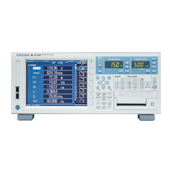
YOKOGAWA WT1800 User Manual
Precision power analyzer
communication interface
Hide thumbs
Also See for WT1800:
- User manual (167 pages) ,
- User manual (167 pages) ,
- User manual (161 pages)

Related Manuals for YOKOGAWA WT1800


Summary of Contents for YOKOGAWA WT1800
- Page 1 WT1800 Precision Power Analyzer Communication Interface IM WT1801-17EN 4th Edition...
- Page 2 To ensure correct use, please read this manual thoroughly before operation. Keep this manual in a safe place for quick reference in the event a question arises. List of Manuals The following manuals, including this one, are provided as manuals for the WT1800. Please read all the manuals. Manual Title Manual No.
-
Page 3: Usb Interface
• To use the USB communication features, your PC must have the following: • WT1800 library (TMCTL) • USB device driver for connecting the WT1800 to the PC • To use the Ethernet communication features, your PC must have the following: •... -
Page 4: How To Use This Manual
How to Use This Manual Structure of the Manual This manual contains six chapters and an appendix. Chapter 1 Ethernet Interface Describes the features and specifications of the Ethernet interface. Chapter 2 USB Interface Describes the features and specifications of the USB interface. Chapter 3 GP-IB Interface Describes the GP-IB interface features and specifications. - Page 5 How to Use This Manual Symbols and Notation Used in This Manual Notes and Cautions The notes and cautions in this manual are categorized using the following symbols. WARNING Calls attention to actions or conditions that could cause serious or fatal injury to the user, and precautions that can be taken to prevent such occurrences.
-
Page 6: Table Of Contents
Component Names and Functions ................... 1-1 1.2 Ethernet Interface Features and Specifications ............... 1-2 Connecting to the Ethernet Interface ................1-3 1.4 Configuring the WT1800 Ethernet Settings ..............1-4 Chapter 2 USB Interface Component Names and Functions ................... 2-1 2.2 USB Interface Features and Specifications ..............2-2 Connecting to the USB Interface ..................2-3 2.4... - Page 7 Contents 5.21 SYSTem Group ......................5-97 5.22 WAVeform Group ......................5-100 5.23 Common Command Group ..................5-102 Chapter 6 Status Reports About Status Reports ....................... 6-1 Status Byte ........................6-3 Standard Event Register ....................6-4 Extended Event Register ....................6-5 Output and Error Queues ....................
-
Page 8: Chapter 1 Ethernet Interface
WT1800 keys. This key is disabled when local lockout (see page 1-2) has been activated by a controller. UTILITY key (page 1-5) -
Page 9: Ethernet Interface Features And Specifications
Switching between Remote and Local Modes Switching from Local to Remote Mode The WT1800 switches to remote mode when it is in local mode and it receives a :COMMunicate: REMote ON command from the PC. • The REMOTE indicator illuminates. -
Page 10: Connecting To The Ethernet Interface
RJ-45 modular jack Notes about Connections • To connect the WT1800 to a PC, be sure to use straight cables and to connect through a hub or router. Proper operation is not guaranteed for a one-to-one connection using a crossover cable. -
Page 11: Configuring The Wt1800 Ethernet Settings
Configuring the WT1800 Ethernet Settings This section explains the following setting for remotely controlling the WT1800 via the Ethernet interface: • Network connection timeout setting UTILITY Remote Control Menu Press UTILITY, the Remote Control soft key, and then the Network soft key to display the following screen. -
Page 12: Chapter 2 Usb Interface
WT1800 keys. This key is disabled when local lockout (see page 2-2) has been activated by a controller. UTILITY key (page 2-4) -
Page 13: Usb Interface Features And Specifications
Switching between Remote and Local Modes Switching from Local to Remote Mode The WT1800 switches to remote mode when it is in local mode and it receives a :COMMunicate: REMote ON command from the PC. • The REMOTE indicator illuminates. -
Page 14: Connecting To The Usb Interface
• Be sure to insert the USB cable connector firmly into the USB port. • If you are connecting multiple devices by using a USB hub, connect the WT1800 to the USB hub port that is closest to the port that the controller is connected to. -
Page 15: Configuring The Wt1800 Usb Settings
Install the YOKOGAWA USB TMC (Test and Measurement Class) driver on your PC. For information about how to obtain the YOKOGAWA USB TMC driver, contact your nearest YOKOGAWA dealer. You can also access the YOKOGAWA USB driver download web page and download the driver. -
Page 16: Chapter 3 Gp-Ib Interface
WT1800 keys. This key is disabled when local lockout (see page 3-7) has been activated by a controller. UTILITY key (page 3-6) Press this key to set the GP-IB address. -
Page 17: Gp-Ib Interface Features And Specifications
• Commands such as status report commands can be received. Talker Capability The WT1800 can transmit measured and computed data. The WT1800 can transmit panel setup parameters and the status byte. The WT1800 can transmit error codes when errors occur. Note Talk-only, listen-only, and controller capabilities are not available on the WT1800. - Page 18 Switching between Remote and Local Modes Switching from Local to Remote Mode The WT1800 switches to remote mode when it is in local mode and it receives a REN (Remote Enable) message from the PC. • The REMOTE indicator illuminates.
-
Page 19: Connecting To The Gp-Ib Interface
• On the PC end, use a GP-IB board (or card) made by National Instruments. For details, see section 3.2. • The WT1800 may not operate properly if the WT1800 is connected to the PC through converters (such as a GP-IB to USB converter). For more details, contact your nearest YOKOGAWA dealer. - Page 20 3.3 Connecting to the GP-IB Interface CAUTION Be sure to turn off the PC and the WT1800 when connecting or removing communication cables. Otherwise, erroneous operation may result, or the internal circuitry may break. Index IM WT1801-17EN...
-
Page 21: Configuring The Wt1800 Gp-Ib Settings
Only use one communication interface: GP-IB, USB, or Network. If you send commands simultaneously from more than one communication interface, the WT1800 will not execute the commands properly. • When the controller is communicating with the WT1800 or with other devices through GP-IB, do not change the address. •... -
Page 22: Responses To Interface Messages
Responses to Interface Messages Responses to Interface Messages Responses to Uni-Line Messages • IFC (Interface Clear) Clears the talker and listener functions. Stops data transmission if it is in progress. • REN (Remote Enable) Switches between the remote and local modes. IDY (Identify) is not supported. - Page 23 Secondary address address commands The WT1800 supports interface messages marked with a Note Difference between SDC and DCL In multi-line messages, SDC messages are address commands that require talker or listener designation and DCL messages are universal commands that do not require a designation. Therefore, SDC messages are directed at a particular instrument while DCL messages are directed at all instruments on the bus.
-
Page 24: Chapter 4 Programming Overview
Program Message Unit Syntax Messages are used to exchange information between The program message unit syntax is shown below. the controller and the WT1800. Messages that are sent from the controller to the WT1800 are called <Program header> Space <Program data>... - Page 25 If both the transmit and receive If there are multiple data values, each data value is buffers become full at the same time, the WT1800 will separated by a comma. For details, see page 4-5. no longer be able to operate. This condition is called a Example deadlock.
-
Page 26: Commands
Commands Commands Example A portion of the commands from the There are three types of commands (program headers) integration command group that a controller may send to the WT1800. The :INTEGrate? commands differ in their program header formats. :INTEGrate:MODE :INTEGrate:TIMer... - Page 27 0,0,0; ACAL 0<RMT> The response to an upper-level query can be sent back to the WT1800 as a program message. This enables the settings that were present when the upper- level query was made to be reproduced later on. However, some upper-level queries do not return setup parameters that are not currently in use.
-
Page 28: Responses
Abbreviated Form The WT1800 normally returns response headers with the lower-case section removed. You can configure the WT1800 so that full headers are returned. Use the COMMunicate:VERBose command for this purpose. The sections enclosed in square brackets ([ ]) are also omitted in the abbreviated form. -
Page 29: Data
<NR1> to “MHZ.” Therefore, “M (Milli)” cannot be used for <NR3>. This is expressed as <NRf>. • The WT1800 returns a response to the controller in frequencies. one of the forms from <NR1> to <NR3> depending •... - Page 30 <Block Data> <Block data> is any 8-bit data. It is only used in <Character Data> response messages on the WT1800. The syntax is as <Character data> is a predefined character string (a follows: mnemonic). It is mainly used to indicate that an option...
-
Page 31: Synchronization With The Controller
If you specify the voltage range and send the next INPut:VOLTage:RANGe: program message while you are querying the result, ELEMent1?<PMT> the WT1800 always returns the most recent setting (100 COMMunicate:OVERlap #HFFBF enables V in this case). overlapping for commands other than media access. - Page 32 :NUMeric[: NORMal]:VALue? command with some arbitrary (Read the response to STATus:EESR? ) Loop timing. However, because the WT1800 returns the COMMunicate:WAIT 1<PMT> current measured data regardless of whether the :NUMeric[:NORMal]:VALue?<PMT> measured data has been updated since the previous...
-
Page 33: Chapter 5 Commands
:COMMunicate:OVERlap Sets or queries the commands that operate as overlap commands. 5-19 :COMMunicate:REMote Sets the WT1800 to remote or local mode. On is remote mode. 5-20 :COMMunicate:VERBose Sets or queries whether the response to a query is returned fully spelled 5-20 out (example: “:INPUT:VOLTAGE:RANGE:ELEMENT1 1.000E+03”) or in its... - Page 34 5.1 List of Commands Command Function Page :CURSor:TRENd? Queries all trend display cursor measurement settings. 5-21 :CURSor:TRENd:LINKage Sets or queries the on/off status of the cursor position linkage on the trend 5-21 display. :CURSor:TRENd:POSition<x> Sets or queries the position of the specified cursor on the trend display. 5-21 :CURSor:TRENd[:STATe] Sets or queries the on/off status of the cursor display on the trend display.
- Page 35 5.1 List of Commands Command Function Page :DISPlay:NUMeric:CUSTom:FILE:LO Aborts a file loading operation for the numeric display in custom display 5-26 AD:ABORt mode. :DISPlay:NUMeric:CUSTom:FILE:LO Loads the specified background file for the numeric display in custom display 5-26 AD:BMP mode. :DISPlay:NUMeric:CUSTom:FILE:LO Loads the specified display configuration and background files for the 5-26 AD:BOTH...
- Page 36 5.1 List of Commands Command Function Page :DISPlay:NUMeric[:NORMal]:MATRi Sets or queries the number of columns of the numeric display in matrix 5-31 x:COLumn:NUMber display mode. :DISPlay:NUMeric[:NORMal]:MATRi Resets the column display items to their default values on the numeric 5-31 x:COLumn:RESet display in matrix display mode.
- Page 37 5.1 List of Commands Command Function Page :DISPlay:WAVE:TRIGger? Queries all trigger settings. 5-37 :DISPlay:WAVE:TRIGger:LEVel Sets or queries the trigger level. 5-37 :DISPlay:WAVE:TRIGger:MODE Sets or queries the trigger mode. 5-37 :DISPlay:WAVE:TRIGger:SLOPe Sets or queries the trigger slope. 5-37 :DISPlay:WAVE:TRIGger:SOURce Sets or queries the trigger source. 5-37 :DISPlay:WAVE:{U<x>|I<x>|SPEed| Sets or queries the on/off status of the voltage, current, rotating speed,...
- Page 38 5.1 List of Commands Command Function Page :HARMonics<x>:THD Sets or queries the equation used to compute the THD (total harmonic 5-45 distortion). HCOPy Group :HCOPy? Queries all print settings. 5-46 :HCOPy:ABORt Aborts a print operation. 5-46 :HCOPy:AUTO? Queries all auto print settings. 5-46 :HCOPy:AUTO:COUNt Sets or queries the auto print count.
- Page 39 5.1 List of Commands Command Function Page :HSPeed:RECord:FILE:CDIRectory Changes the directory that acquired numeric data will be saved to. 5-51 :HSPeed:RECord:FILE:CONVert? Queries all settings related to the conversion of files of acquired numeric 5-51 data into CSV format. :HSPeed:RECord:FILE:CONVert:ABO Aborts the conversion of the specified file of acquired numeric data to CSV 5-51 format.
- Page 40 5.1 List of Commands Command Function Page INPut Group :INPut? Queries all input element settings. 5-57 [:INPut]:CFACtor Sets or queries the crest factor. 5-57 [:INPut]:CURRent? Queries all electric current measurement settings. 5-57 [:INPut]:CURRent:AUTO? Queries the electric current auto range on/off statuses of all elements. 5-57 [:INPut]:CURRent:AUTO[:ALL] Collectively sets the electric current auto range on/off status of all elements.
- Page 41 5.1 List of Commands Command Function Page [:INPut]:MODUle? Queries the input element type. 5-62 [:INPut]:NULL:CONDition:{SPEed| Queries the status of the NULL operation of rotating speed, torque, or AUX. 5-62 TORQue|AUX<x>} [:INPut]:NULL:CONDition:{U<x>|I Queries the status of the voltage or current NULL operation of the specified 5-62 <x>} element.
- Page 42 5.1 List of Commands Command Function Page INTEGrate Group :INTEGrate? Queries all integration settings. 5-67 :INTEGrate:ACAL Sets or queries the on/off status of integration auto calibration. 5-67 :INTEGrate:INDependent Sets or queries the on/off status of independent element integration. 5-67 :INTEGrate:MODE Sets or queries the integration mode.
- Page 43 5.1 List of Commands Command Function Page :MEASure:EVENt<x>:TLABel Sets or queries the string that is displayed when the specified user-defined 5-73 event’s condition is met. :MEASure:FREQuency? Queries all frequency measurement settings. 5-73 :MEASure:FREQuency:ITEM<x> Sets or queries the element whose frequency will be measured. 5-73 :MEASure:FUNCtion<x>? Queries all the settings of the specified user-defined function.
- Page 44 5.1 List of Commands Command Function Page :MOTor:SPEed:TYPE Sets or queries the revolution signal input type. 5-77 :MOTor:SPEed:UNIT Sets or queries the unit that is added to the rotating speed computation 5-77 result. :MOTor:SSPeed Sets or queries the frequency measurement source for the synchronous 5-77 speed (SyncSp) computation.
- Page 45 :STORe:COUNt Sets or queries the storage count. 5-94 :STORe:FILE? Queries all settings related to the saving of the data stored in the WT1800 to 5-94 files. :STORe:FILE:ANAMing Sets or queries the auto naming feature for saving stored numeric data to 5-94 files.
- Page 46 5.1 List of Commands Command Function Page :STORe:NUMeric[:NORMal]:PRESet Presets the output on/off pattern of the element functions to be used when 5-96 <x> numeric data is stored. :STORe:RESet Resets the numeric data storage feature. 5-96 :STORe:RTIMe? Queries the storage start and end times for real-time storage mode. 5-96 :STORe:RTIMe:{STARt|END} Sets or queries the storage start or end time for real-time storage mode.
- Page 47 5.1 List of Commands Command Function Page WAVeform Group :WAVeform? Queries all waveform display data output settings. 5-100 :WAVeform:BYTeorder Sets or queries the output byte order of the waveform display data (FLOAT 5-100 format) that is transmitted by the :WAVeform:SEND? command. :WAVeform:END Sets or queries the output end point of the waveform display data that is 5-100...
-
Page 48: Aoutput Group
AOUTput Group The commands in this group deal with D/A output. You can make the same settings and queries that you can make by pressing UTILITY on the front panel, and then using the D/A Output Items menu. The commands in this group are only valid on models with the D/A output (/DA) option. :AOUTput? :AOUTput[:NORMal]:IRTime Function... -
Page 49: Aux Group
AUX Group The commands in this group deal with the auxiliary input feature. You can make the same settings and queries that you can make by pressing MOTOR/AUX SET (SHIFT+SCALING) on the front panel. The commands in this group are only valid on models with the auxiliary input (/AUX) option. :AUX<x>? :AUX<x>:LSCale:AVALue Function... - Page 50 Syntax <x> = 1 or 2 (AUX input channel) :AUX1:LSCALE:CALCULATE:EXECUTE Example Description The WT1800 uses the data that has been specified (Point1X, Point1Y, Point2X, and Point2Y) to calculate and set the slope (A) and offset (B) of the linear scale.
-
Page 51: Communicate Group
COMMunicate Group The commands in this group deal with communications. There are no front panel keys that correspond to the commands in this group. :COMMunicate? :COMMunicate:OPSR? Function Queries all communication settings. Function Queries the operation pending status register. :COMMunicate? :COMMunicate:OPSR? Syntax Syntax :COMMunicate:OPSR? ->... - Page 52 5.4 COMMunicate Group :COMMunicate:REMote Function Sets the WT1800 to remote or local mode. On is remote mode. :COMMunicate:REMote {<Boolean>} Syntax :COMMunicate:REMote? :COMMUNICATE:REMOTE ON Example :COMMUNICATE:REMOTE? -> :COMMUNICATE:REMOTE 1 :COMMunicate:VERBose Function Sets or queries whether the response to a query is returned fully spelled out (example: “:INPUT: VOLTAGE:RANGE:ELEMENT1 1.000E+03”) or...
-
Page 53: Cursor Group
CURSor Group The commands in this group deal with cursor measurements. You can make the same settings and queries (of settings and measured values) that you can make by pressing CURSOR (SHIFT+FORM) on the front panel. :CURSor? :CURSor:BAR:{Y<x>|DY}? Function Queries all cursor measurement settings. Function Queries the measured value of the specified :CURSor? - Page 54 5.5 CURSor Group :CURSor:TRENd:TRACe<x> :CURSor:WAVE:POSition<x> Function Sets or queries the target of the specified cursor Function Sets or queries the position of the specified on the trend display. cursor on the waveform display. :CURSor:TRENd:TRACe<x> {<NRf>} :CURSor:WAVE:POSition<x> {<NRf>} Syntax Syntax :CURSor:WAVE:POSition<x>? :CURSor:TRENd:TRACe<x>? <x>...
- Page 55 DISPlay Group The commands in this group deal with the display. You can make the same settings and queries that you can make by pressing the keys in the front panel DISPLAY and ITEM & ELEMENT areas. :DISPlay? :DISPlay:BAR:ITEM<x>:SCALing? Function Queries all display settings.
- Page 56 5.6 DISPlay Group :DISPlay:BAR:ITEM<x>:SCALing: :DISPlay:HSPeed? VERTical Function Queries all high speed data capturing display Function Sets or queries the vertical scaling mode of the settings. :DISPlay:HSPeed? specified bar graph. Syntax :DISPlay:BAR:ITEM<x>:SCALing: Syntax Description The bar graph display is only available on models VERTical {LINear|LOG} with the high speed data capturing (/HS) option.
-
Page 57: Display Group
5.6 DISPlay Group :DISPlay:HSPeed:PAGE :DISPlay:MODE Function Sets or queries the displayed page of the high Function Sets or queries the display mode. :DISPlay:MODE {NUMeric|WAVE|TRENd| speed data capturing mode. Syntax BAR|VECTor|NWAVe|NTRend|NBAR| :DISPlay:HSPeed:PAGE {<NRf>} Syntax NVECtor|WNUMeric|WTRend|WBAR| :DISPlay:HSPeed:PAGE? WVECtor|TNUMeric|TWAVe|TBAR|TVECtor| <NRf> = 1 to 2 (page number) HSPeed} <NRf>... - Page 58 5.6 DISPlay Group :DISPlay:NUMeric:CUSTom:FILE:DRIVe :DISPlay:NUMeric:CUSTom:FILE:LOAD: ITEM Function Sets the drive that files are loaded from or saved to for the numeric display in custom display Function Loads the specified display configuration file for mode. the numeric display in custom display mode. :DISPlay:NUMeric:CUSTom:FILE: :DISPlay:NUMeric:CUSTom:FILE:LOAD: Syntax...
- Page 59 :DISPLAY:NUMERIC:CUSTOM:ITEM1: BGRAY = Blue gray FUNCTION UK,1,1 BLACk = Black • When setting a string :DISPLAY:NUMERIC:CUSTOM:ITEM1: :DISPLAY:NUMERIC:CUSTOM:ITEM1: Example COLOR WHITE FUNCTION "YOKOGAWA" :DISPLAY:NUMERIC:CUSTOM:ITEM1: :DISPLAY:NUMERIC:CUSTOM:ITEM1: COLOR? -> FUNCTION? -> :DISPLAY:NUMERIC:CUSTOM:ITEM1: :DISPLAY:NUMERIC:CUSTOM:ITEM1: COLOR WHITE FUNCTION "YOKOGAWA" Description • Set a numeric item or a string as a display item.
- Page 60 5.6 DISPlay Group :DISPlay:NUMeric:CUSTom:ITEM<x>: :DISPlay:NUMeric:CUSTom:PERPage POSition Function Sets or queries the number of items displayed Function Sets or queries the display position of the per page of the numeric display in custom display specified display item of the numeric display in mode.
- Page 61 5.6 DISPlay Group :DISPlay:NUMeric[:NORMal]:ALL: :DISPlay:NUMeric[:NORMal]:ALL:CURSor COLumn? Function Sets or queries the cursor position on the numeric Function Queries all column settings of the numeric display display in All Items display mode. :DISPlay:NUMeric[:NORMal]:ALL: in All Items display mode. Syntax :DISPlay:NUMeric[:NORMal]:ALL: CURSor {<Function>} Syntax COLumn? :DISPlay:NUMeric[:NORMal]:ALL:...
- Page 62 5.6 DISPlay Group :DISPlay:NUMeric[:NORMal]:FORMat :DISPlay:NUMeric[:NORMal]:LIST: Function Sets or queries the numeric display format. HEADer :DISPlay:NUMeric[:NORMal]:FORMat Syntax Function Sets or queries the cursor position of the header {VAL4|VAL8|VAL16|MATRix|ALL|SINGle| section on the numeric display in the list display DUAL|CUSTom} modes. :DISPlay:NUMeric[:NORMal]:FORMat? :DISPlay:NUMeric[:NORMal]:LIST: Syntax :DISPLAY:NUMERIC:NORMAL:FORMAT VAL4 Example...
- Page 63 5.6 DISPlay Group :DISPlay:NUMeric[:NORMal]:LIST:ORDer :DISPlay:NUMeric[:NORMal]:MATRix: COLumn:NUMber Function Sets or queries the harmonic order cursor position of the data section on the numeric display in the Function Sets or queries the number of columns of the list display modes. numeric display in matrix display mode. :DISPlay:NUMeric[:NORMal]:LIST: :DISPlay:NUMeric[:NORMal]:MATRix: Syntax...
- Page 64 ITEM1 UK,1,1 items are reset using the ITEM setup menu that is displayed on the WT1800 screen (Reset Items :DISPLAY:NUMERIC:NORMAL:MATRIX: Exec). For details on the display pattern that ITEM1? ->...
- Page 65 ITEM setup menu that is displayed on the WT1800 screen (Reset Items Exec). For details on the display pattern that appears when the displayed items are reset, see the getting started guide, IM WT1801-03EN.
- Page 66 5.6 DISPlay Group :DISPlay:TRENd:CLEar :DISPlay:TRENd:ITEM<x>:SCALing? Function Clears all trends. Function Queries all scaling settings for the specified trend. :DISPlay:TRENd:CLEar :DISPlay:TRENd:ITEM<x>:SCALing? Syntax Syntax :DISPLAY:TREND:CLEAR <x> = 1 to 16 (item number) Example :DISPlay:TRENd:FORMat :DISPlay:TRENd:ITEM<x>:SCALing:MODE Function Sets or queries the display format of all trends. Function Sets or queries the scaling mode of the specified :DISPlay:TRENd:FORMat {SINGle|DUAL|...
- Page 67 5.6 DISPlay Group :DISPlay:TRENd:TDIV :DISPlay:VECTor:ITEM<x>:{UMAG|IMAG} Function Sets or queries the trend horizontal axis (T/div). Function Sets or queries the voltage or current zoom factor :DISPlay:TRENd:TDIV {<NRf>,<NRf>, Syntax for the vector display. <NRf>} :DISPlay:VECTor:ITEM<x>:{UMAG|IMAG} Syntax :DISPlay:TRENd:TDIV? {<NRf>} {<NRf>,<NRf>,<NRf>} = 0, 0, 3 to :DISPlay:VECTor:ITEM<x>:{UMAG|IMAG}? 24, 0, 0 <x>...
- Page 68 5.6 DISPlay Group :DISPlay:WAVE:INTerpolate :DISPlay:WAVE:POSition:{U<x>|I<x>} Function Sets or queries the waveform interpolation Function Sets or queries the vertical position (center method. position level) of the specified element’s voltage :DISPlay:WAVE:INTerpolate {OFF|LINE} Syntax or current waveform. :DISPlay:WAVE:INTerpolate? :DISPlay:WAVE:POSition:{U<x>|I<x>} Syntax :DISPLAY:WAVE:INTERPOLATE LINE {<NRf>} Example :DISPLAY:WAVE:INTERPOLATE? ->...
- Page 69 5.6 DISPlay Group :DISPlay:WAVE:TRIGger? :DISPlay:WAVE:{U<x>|I<x>|SPEed| TORQue|AUX<x>} Function Queries all trigger settings. :DISPlay:WAVE:TRIGger? Syntax Function Sets or queries the on/off status of the voltage, current, rotating speed, torque, or auxiliary signal :DISPlay:WAVE:TRIGger:LEVel waveform display. :DISPlay:WAVE:{U<x>|I<x>|SPEed| Function Sets or queries the trigger level. Syntax :DISPlay:WAVE:TRIGger:LEVel {<NRf>} TORQue|AUX<x>} {<Boolean>}...
- Page 70 5.6 DISPlay Group * Function Option List (Settings That Can Be Used for <Function>) (1) Numeric data functions Applicable commands :AOUTput[:NORMal]:CHANnel<x> {NONE|<Function>[,<Element>][,<Order>]} :DISPlay:NUMeric:CUSTom:ITEM<x>[:FUNCtion] {<Function>[,<Element>] [,<Order>]|<String>} :DISPlay:NUMeric[:NORMal]:{VAL4|VAL8|VAL16}:ITEM<x> {NONE|<Function> [,<Element>][,<Order>]} :DISPlay:NUMeric[:NORMal]:MATRix:ITEM<x> {NONE|<Function>[,<Element>] [,<Order>]} :DISPlay:NUMeric[:NORMal]:ALL:CURSor {<Function>} :DISPlay:TRENd:ITEM<x>[:FUNCtion] {<Function>,<Element>[,<Order>]} :FILE:SAVE:NUMeric:NORMal:<Function> {<Boolean>} :MEASure:EVENt<x>:EXPRession:ITEM {<Function>[,<Element>][,<Order>]} :NUMeric[:NORMal]:ITEM<x> {NONE|<Function>[,<Element>][,<Order>]} :STORe:NUMeric[:NORMal]:<Function>...
- Page 71 5.6 DISPlay Group Functions That Require the Harmonic Measurement (/G5 or /G6) Option U(k) Required Required I(k) Required Required P(k) Required Required S(k) Required Required Q(k) Required Required LAMBDAK λ(k) Required Required PHIK φ(k) Required Required PHIUk φU(k) Required Required PHIIk φI(k) Required...
- Page 72 5.6 DISPlay Group Functions That Require the Delta Computation (/DT) Option ΔU1 Required (only Σ) Not required ΔU2 Required (only Σ) Not required ΔU3 Required (only Σ) Not required ΔUΣ Required (only Σ) Not required ΔI Required (only Σ) Not required ΔP1 Required (only Σ) Not required ΔP2 Required (only Σ) Not required ΔP3 Required (only Σ) Not required ΔPΣ...
- Page 73 5.6 DISPlay Group (2) Numeric list data functions (these functions require the harmonic measurement option) Applicable commands :DISPlay:BAR:ITEM<x>[:FUNCtion] {<Function>,<Element>} :DISPlay:NUMeric[:NORMal]:LIST:ITEM<x> {<Function>,<Element>} :NUMeric:LIST:ITEM<x> {NONE|<Function>,<Element>} <Function> Function Name Used on the Menu LAMBda λ φ PHIU φU PHII φI The function options listed below are only valid with :NUMeric:LIST:ITEM<x>. UHDF Uhdf IHDF...
-
Page 74: File Group
FILE Group The commands in this group deal with file operations. You can perform the same operations and make the same settings and queries that you can make by pressing FILE on the front panel. :FILE? :FILE:DELete:WAVE:ASCii Function Queries all file operation settings. Function Deletes the specified waveform display data file. - Page 75 5.7 FILE Group :FILE:SAVE? :FILE:SAVE:NUMeric:NORMal? Function Queries all file save settings. Function Queries all numeric data file save settings (for the :FILE:SAVE? Syntax manual save item selection method). :FILE:SAVE:NUMeric:NORMal? Syntax :FILE:SAVE:ABORt Description This command is valid when the save item Function Aborts a file saving operation.
- Page 76 5.7 FILE Group :FILE:SAVE:NUMeric:NORMal:PRESet<x> Function Presets the output on/off pattern of the element functions to be used when numeric data is saved to a file. :FILE:SAVE:NUMeric:NORMal:PRESet<x> Syntax <x> = 1 or 2 (preset number) :FILE:SAVE:NUMERIC:NORMAL:PRESET1 Example Description For details on the output setting patterns that result when the pattern is reset, see the features guide, IM WT1801-01EN.
-
Page 77: Harmonics Group
HARMonics Group The commands in this group deal with harmonic measurement. You can make the same settings and queries that you can make by pressing HRM SET on the front panel. The commands in this group are only valid on models with the simultaneous dual harmonic measurement (/G6) option or the harmonic measurement (/G5) option. -
Page 78: Hcopy Group
HCOPy Group The commands in this group deal with printing on the built-in printer. You can make the same settings and queries that you can make by pressing PRINT and MENU (SHIFT+PRINT) on the front panel. The commands in this group are only valid on models with the built-in printer (/B5) option. :HCOPy:AUTO:MODE :HCOPy? Function... - Page 79 5.9 HCOPy Group :HCOPy:AUTO[:STATe] :HCOPy:PRINter:FORMat Function Sets or queries the auto print feature’s on/off Function Sets or queries the contents that will be printed status. from the built-in printer. :HCOPy:AUTO[:STATe] {<Boolean>} :HCOPy:PRINter:FORMat {SCReen|LIST} Syntax Syntax :HCOPy:AUTO:STATe? :HCOPy:PRINter:FORMat? :HCOPy:AUTO:STATE OFF SCReen = Screen image data Example :HCOPy:AUTO:STATE? ->...
-
Page 80: Hold Group
5.10 HOLD Group The command in this group deals with the output data hold feature. You can make the same settings and queries that you can make by pressing HOLD on the front panel. :HOLD Function Sets or queries the on/off status of the output hold feature for display, communication, and other types of data. -
Page 81: Hspeed Group
5.11 HSPeed Group The commands in this group deal with the high speed data capturing feature. These commands allow you to enter and query the same settings that are available under ITEM in the “HS Items” menu and under FORM in the “HS Settings” menu on the front panel. The commands in this group are only valid on models with the high speed data capturing (/HS) option. - Page 82 5.11 HSPeed Group :HSPeed:DISPlay:PAGE :HSPeed:FILTer:LINE[:ALL] Function Sets or queries the display page of high speed Function Sets the line filters of all the high speed data data capturing mode. capturing elements. :HSPeed:DISPlay:PAGE {<NRf>} :HSPeed:FILTer:LINE Syntax Syntax :HSPeed:DISPlay:PAGE? [:ALL] {<Frequency>} <NRf> = 1 or 2 (page number) <Frequency>...
- Page 83 5.11 HSPeed Group :HSPeed:MEASuring:{U<x>|I<x>} :HSPeed:RECord:FILE:ANAMing Function Sets or queries the specified voltage or current Function Sets or queries the auto naming feature for mode. saving acquired numeric data to files. :HSPeed:MEASuring:{U<x>|I<x>} {RMS| Syntax :HSPeed:RECord:FILE:ANAMing {OFF| Syntax MEAN|DC|RMEAN} NUMBering|DATE} :HSPeed:MEASuring:{U<x>|I<x>}? :HSPeed:RECord:FILE:ANAMing? <x>...
- Page 84 • CONVert = Stored data is being converted to PM}? CSV format. :HSPEED:RECORD:ITEM:SPEED ON Example • OFF = The WT1800 is not configured to save :HSPEED:RECORD:ITEM:SPEED? -> captured data to files, or the WT1800 is not in :HSPEED:RECORD:ITEM:SPEED 1 high speed data capturing mode.
- Page 85 Sets, at the same time, whether all numeric data STARt = High-speed data capturing is being items will be saved. performed. :HSPeed:RECord:ITEM:PRESet: Syntax OFF = The WT1800 is not in high speed data ALL {<Boolean>} capturing mode. :HSPEED:RECORD:ITEM:PRESET:ALL ON Example :HSPeed:STOP :HSPeed:RECord:ITEM:PRESet:{ELEMent<...
- Page 86 5.11 HSPeed Group :HSPeed:TRIGger:SLOPe Function Sets or queries the trigger slope. :HSPeed:TRIGger:SLOPe {RISE|FALL| Syntax BOTH} :HSPeed:TRIGger:SLOPe? :HSPEED:TRIGGER:SLOPE RISE Example :HSPEED:TRIGGER:SLOPE? -> :HSPEED:TRIGGER:SLOPE RISE Description This command performs the same setting as the “: DISPlay:WAVE:TRIGger:SLOPe” command. :HSPeed:TRIGger:SOURce Function Sets or queries the trigger source. :HSPeed:TRIGger:SOURce {U<x>|I<x>| Syntax EXTernal}...
-
Page 87: Image Group
5.12 IMAGe Group The commands in this group deal with saving screen image data. You can perform the same operations and make the same settings and queries that you can by pressing IMAGE SAVE and MENU (SHIFT+IMAGE SAVE) on the front panel. - Page 88 5.12 IMAGe Group :IMAGe:SAVE:NAME Function Sets or queries the name of the file that will be saved. :IMAGe:SAVE:NAME {<String>} Syntax :IMAGe:SAVE:NAME? <String> = File name :IMAGE:SAVE:NAME "IMAGE1" Example :IMAGE:SAVE:NAME? -> :IMAGE:SAVE:NAME "IMAGE1" Description • Use the :IMAGe:SAVE:DRIVe command to set the save destination drive and the : IMAGe:SAVE:CDIRectory command to set the directory.
- Page 89 5.13 INPut Group The commands in this group deal with the measurement conditions of the input elements. You can make the same settings and queries that you can make by pressing the keys in the measurement condition setup area (the area outlined in blue), SCALING, LINE FILTER, FREQ FILTER (SHIFT+LINE FILTER), SYNC SOURCE, NULL, and NULL SET (SHIFT+NULL) on the front panel.
- Page 90 5.13 INPut Group [:INPut]:CURRent:CONFig:ELEMent<x> [:INPut]:CURRent:EXTSensor:CONFig: ELEMent<x> Function Sets or queries the valid electric current range of the specified element. Function Sets or queries the valid external current sensor [:INPut]:CURRent:CONFig:ELEMent<x> Syntax ranges of the specified element. {ALL|<Current>[,<Current>][,<Current [:INPut]:CURRent:EXTSensor:CONFig: Syntax >]...} ELEMent<x> {ALL|<Voltage>[, [:INPut]:CURRent:CONFig:ELEMent<x>? <Voltage>][,<Voltage>]...} <x>...
-
Page 91: Input Group
5.13 INPut Group [:INPut]:CURRent:EXTSensor: [:INPut]:CURRent:POJump[:ALL] POJump[:ALL] Function Collectively sets the jump destination range of all Function Collectively sets the jump destination range of all elements that is used when a current peak over- elements that is used when a current peak over- range occurs. - Page 92 5.13 INPut Group [:INPut]:CURRent:RANGe[:ALL] [:INPut]:CURRent:RANGe: {SIGMA|SIGMB|SIGMC} Function Collectively sets the electric current range of all elements. Function Collectively sets the electric current range of all [:INPut]:CURRent:RANGe[:ALL] {<Curre Syntax the elements that belong to the specified wiring nt>|(EXTernal,<Voltage>)} unit (ΣA, ΣB, or ΣC). [:INPut]:CURRent:RANGe:{SIGMA|SIGMB| • 50 A input elements Syntax •...
- Page 93 5.13 INPut Group [:INPut]:CURRent:SRATio: [:INPut]:FILTer:FREQuency:ELEMent<x> {SIGMA|SIGMB|SIGMC} Function Sets or queries the frequency filter of the Function Collectively sets the external current sensor specified element. [:INPut]:FILTer:FREQuency: conversion ratios of all the elements that belong Syntax ELEMent<x> {OFF|<Frequency>} to the specified wiring unit (ΣA, ΣB, or ΣC). [:INPut]:CURRent:SRATio: [:INPut]:FILTer:FREQuency: Syntax {SIGMA|SIGMB|SIGMC} {<NRf>} ELEMent<x>? <NRf>...
- Page 94 5.13 INPut Group [:INPut]:FILTer[:LINE]: [:INPut]:NULL:CONDition:{U<x>|I<x>} {SIGMA|SIGMB|SIGMC} Function Queries the status of the voltage or current NULL Function Collectively sets the line filter of all the elements operation of the specified element. [:INPut]:NULL:CONDition:{U<x>|I<x>}? that belong to the specified wiring unit (ΣA, ΣB, or Syntax <x> = 1 to 6 (element) ΣC).
- Page 95 5.13 INPut Group [:INPut]:NULL:TARGet:{U<x>|I<x>} [:INPut]:SCALing:STATe? Function Sets or queries the target of the voltage or current Function Queries the on/off statuses of the scaling of all NULL operation of the specified element. elements. [:INPut]:NULL:TARGet:{U<x>| [:INPut]:SCALing:STATe? Syntax Syntax I<x>} {ON|HOLD|OFF} [:INPut]:SCALing[:STATe][:ALL] [:INPut]:NULL:TARGet:{U<x>|I<x>}? <x>...
- Page 96 5.13 INPut Group [:INPut]:SCALing:{VT|CT|SFACtor}: [:INPut]:VOLTage? {SIGMA|SIGMB|SIGMC} Function Queries all voltage measurement settings. [:INPut]:VOLTage? Function Collectively sets the VT ratio, CT ratio, or power Syntax coefficient of all the elements that belong to the [:INPut]:VOLTage:AUTO? specified wiring unit (ΣA, ΣB, or ΣC). [:INPut]:SCALing:{VT|CT|SFACtor}: Syntax Function Queries the voltage auto range on/off statuses of {SIGMA|SIGMB|SIGMC} {<NRf>} all elements.
- Page 97 5.13 INPut Group [:INPut]:VOLTage:CONFig[:ALL] [:INPut]:VOLTage:POJump[:ALL] Function Collectively sets the valid voltage range of all Function Collectively sets the jump destination range of all elements. elements that is used when a voltage peak over- [:INPut]:VOLTage:CONFig[:ALL] Syntax range occurs. {ALL|<Voltage>[,<Voltage>][, [:INPut]:VOLTage:POJump[:ALL] Syntax <Voltage>]...} {OFF|<Voltage>} ALL = All ranges are valid.
- Page 98 5.13 INPut Group [:INPut]:VOLTage:RANGe:ELEMent<x> [:INPut]:WIRing Function Sets or queries the voltage range of the specified Function Sets or queries the wiring system. [:INPut]:WIRing {(P1W2|P1W3|P3W3| element. Syntax [:INPut]:VOLTage:RANGe: P3W4|V3A3)[,(P1W2|P1W3|P3W3|P3W4| Syntax ELEMent<x> {<Voltage>} V3A3)][,(P1W2|P1W3|P3W3|P3W4|V3A3)] [:INPut]:VOLTage:RANGe:ELEMent<x>? [,(P1W2|P1W3|P3W3|P3W4|V3A3)] <x> = 1 to 6 (element) [,(P1W2|P1W3|P3W3)][,P1W2]} <Voltage>...
-
Page 99: Integrate Group
:INTEGRATE:ACAL? -> :INTEGRATE:QMODE:ELEMENT1 DC :INTEGRATE:ACAL 0 Description Regardless of the independent element integration setting (:INTEGrate:INDependent), :INTEGrate:INDependent the WT1800 operates according to the electric Function Sets or queries the on/off status of independent current mode of the specified element. element integration. :INTEGrate:RESet :INTEGrate:INDependent {<Boolean>}... - Page 100 5.14 INTEGrate Group :INTEGrate:RTIMe<x>? :INTEGrate:STARt Function Queries the integration start and end times for Function Starts integration. :INTEGrate:STARt {[<NRf>][,<NRf>] real-time integration mode. Syntax :INTEGrate:RTIMe<x>? [,<NRf>][,<NRf>][,<NRf>][,<NRf>]} Syntax <x> = 1 to 6 (element) <NRf> = 1 to 6 (element) :INTEGRATE:START (starts integration Example :INTEGrate:RTIMe<x>:{STARt|END} on all elements)
- Page 101 Description Regardless of the independent element :INTEGrate:TIMer<x> integration setting (:INTEGrate:INDependent), Function Sets or queries the integration timer value. the WT1800 operates according to the integration :INTEGrate:TIMer<x> {<NRf>,<NRf>, Syntax method of the specified element. <NRf>} :INTEGrate:TIMer<x>? <x> = 1 to 6 (element) {<NRf>,<NRf>,<NRf>} = 0, 0, 0 to 10000, 0,...
-
Page 102: Measure Group
5.15 MEASure Group The commands in this group deal with computation. You can make the same settings and queries that you can make by pressing MEASURE, FREQ MEASURE (SHIFT+MEASURE), and AVG on the front panel or by pressing WIRING on the front panel and then using the η Formula or Δ Measure (/DT option) menu. - Page 103 5.15 MEASure Group :MEASure:EFFiciency? :MEASure:EVENt<x>? Function Queries all efficiency computation settings. Function Queries all the settings of the specified user- :MEASure:EFFiciency? Syntax defined event. :MEASure:EVENt<x>? Syntax :MEASure:EFFiciency:ETA<x> <x> = 1 to 8 (Event1 to Event8) Function Sets or queries the efficiency equation. :MEASure:EFFiciency:ETA<x>...
- Page 104 5.15 MEASure Group :MEASure:EVENt<x>:EXPRession:ITEM :MEASure:EVENt<x>:EXPRession:STRing? Function Sets or queries the target item of the specified Function Queries the specified user-defined event’s user-defined event’s expression (range-defined expression as a string. :MEASure:EVENt<x>:EXPRession:STRing? type). Syntax :MEASure:EVENt<x>:EXPRession:ITEM <x> = 1 to 8 (Event1 to Event8) Syntax {<Function>[,<Element>][,<Order>]} :MEASURE:EVENT1:EXPRESSION:STRING? ->...
- Page 105 5.15 MEASure Group :MEASure:EVENt<x>:TLABel :MEASure:FUNCtion<x>:NAME Function Sets or queries the string that is displayed when Function Sets or queries the name of the specified user- the specified user-defined event’s condition is defined function. :MEASure:FUNCtion<x>:NAME {<String>} met. Syntax :MEASure:EVENt<x>:TLABel {<String>} :MEASure:FUNCtion<x>:NAME? Syntax :MEASure:EVENt<x>:TLABel? <x>...
- Page 106 5.15 MEASure Group :MEASure:PC? :MEASure:SFORmula Function Queries all Pc (Corrected Power) computation Function Sets or queries the equation used to compute S settings. (apparent power). :MEASure:PC? :MEASure:SFORmula {RMS|MEAN|DC| Syntax Syntax MRMS|RMEAN} :MEASure:PC:IEC :MEASure:SFORmula? :MEASURE:SFORMULA RMS Function Sets or queries the Pc (Corrected Power) Example :MEASURE:SFORMULA? ->...
-
Page 107: Motor Group
5.16 MOTor Group The commands in this group deal with the motor evaluation function. You can make the same settings and queries that you can make by pressing MOTOR/AUX SET (SHIFT+SCALING) on the front panel. The commands in this group are only valid on models with the motor evaluation function (/MTR) option. :MOTor? :MOTor:EANGle:CORRection:CLEar Function... - Page 108 :MOTor:SPEed:LSCale? EXECUTE Syntax Description Linear scaling settings are valid when the Description The WT1800 uses the data that has been revolution signal input type (:MOTor:SPEed: specified (Point1X, Point1Y, Point2X, and TYPE) is set to ANALog (analog input). Point2Y) to calculate and set the slope (A) and offset (B) of the linear scale.
- Page 109 5.16 MOTor Group :MOTor:SPEed:PRANge :MOTor:SPEed:TYPE Function Sets or queries the range of the revolution signal Function Sets or queries the revolution signal input type. :MOTor:SPEed:TYPE {ANALog|PULSe} (pulse input type). Syntax :MOTor:SPEed:PRANge {<NRf>,<NRf>} :MOTor:SPEed:TYPE? Syntax :MOTor:SPEed:PRANge? :MOTOR:SPEED:TYPE ANALOG Example <NRf> = 0.0000 to 99999.9999 :MOTOR:SPEED:TYPE? ->...
- Page 110 :MOTor:TORQue:LSCale:AVALue {<NRf>} :MOTOR:TORQUE:LSCALE:CALCULATE: Syntax Example :MOTor:TORQue:LSCale:AVALue? EXECUTE <NRf> = 1.000E-03 to 1.000E+06 Description The WT1800 uses the data that has been :MOTOR:TORQUE:LSCALE:AVALUE 1.000 Example specified (Point1X, Point1Y, Point2X, and :MOTOR:TORQUE:LSCALE:AVALUE? -> Point2Y) to calculate and set the slope (A) and :MOTOR:TORQUE:LSCALE: offset (B) of the linear scale.
- Page 111 5.16 MOTor Group :MOTor:TORQue:RATE? Function Queries all torque signal (pulse input type) rated- value settings. :MOTor:TORQue:RATE? Syntax :MOTor:TORQue:RATE:{UPPer|LOWer} Function Sets or queries the upper or lower limit of the rated value of the torque signal (pulse input type). :MOTor:TORQue:RATE:{UPPer|LOWer} Syntax {<NRf>,<Frequency>} :MOTor:TORQue:RATE:{UPPer|LOWer}? <NRf>...
-
Page 112: Numeric Group
5.17 NUMeric Group The command in this group deal with numeric data output. There are no front panel keys that correspond to the commands in this group. The commands in the DISPlay group are used to make the same settings and queries as the NUMERIC key on the front panel. :NUMeric? :NUMeric:HSPeed:CLEar Function... - Page 113 5.17 NUMeric Group :NUMeric:HSPeed:HEADer? :NUMeric:HSPeed:{MAXimum|MINimum}? Function Queries the header of the numeric data of high Function Queries the maximum or minimum value of the speed data capturing mode. numeric data of high speed data capturing mode. :NUMeric:HSPeed:HEADer? {<NRf>} :NUMeric:HSPeed:{MAXimum| Syntax Syntax <NRf>...
- Page 114 5.17 NUMeric Group :NUMeric:HSPeed:PRESet :NUMeric:HSPeed:VALue? Function Presets the numeric data output item pattern of Function Queries the numeric data of high speed data the high speed data capturing mode. capturing mode. :NUMeric:HSPeed:PRESet {DEFault| :NUMeric:HSPeed:VALue? {<NRf>} Syntax Syntax RECord} <NRf> = 1 to 30 (item number) DEFault = default When there are 100 data records Example...
- Page 115 5.17 NUMeric Group :NUMeric:LIST? • Before data capturing starts or after measurement conditions are changed, the Function Queries all harmonic measurement numeric list number of data captures is “0.” Therefore, data output settings. :NUMeric:LIST? there are no data records. The response that is Syntax returned is described below.
- Page 116 5.17 NUMeric Group :NUMeric:LIST:ITEM<x> :NUMeric:LIST:PRESet Function Sets or queries the output item (function and Function Presets the harmonic measurement numeric list element) of the specified harmonic measurement data output item pattern. :NUMeric:LIST:PRESet {<NRf>} numeric list data item. Syntax :NUMeric:LIST:ITEM<x>{NONE| <NRf> = 1 to 4 Syntax <Function>,<Element>} :NUMERIC:LIST:PRESET 1...
- Page 117 5.17 NUMeric Group :NUMeric:LIST:VALue? :NUMeric[:NORMal]:CLEar Function Queries the harmonic measurement numeric list Function Clears numeric data output items (sets the items data. to NONE). :NUMeric:LIST:VALue? {<NRf>} :NUMeric[:NORMal]:CLEar {ALL| Syntax Syntax <NRf> = 1 to 64 (item number) <NRf>[,<NRf>]} ALL = Clear all items Example •...
- Page 118 5.17 NUMeric Group :NUMeric[:NORMal]:ITEM<x> :NUMeric[:NORMal]:VALue? Function Sets or queries the specified numeric data output Function Queries the numeric data. :NUMeric[:NORMal]:VALue? {<NRf>} item (function, element, and harmonic order). Syntax :NUMeric[:NORMal]:ITEM<x> <NRf> = 1 to 255 (item number) Syntax {NONE|<Function>[,<Element>][,<Order>]} Example • When <NRf> is specified: :NUMeric[:NORMal]:ITEM<x>? :NUMERIC:NORMAL:VALUE? 1 ->...
- Page 119 5.17 NUMeric Group * Numeric Data Formats (1) Normal Data • The Σ of electric power values P, S, and Q • Integrated values WH, WHP, WHM, AH, AHP, AHM, WS, and WQ • Efficiency values ETA1, ETA2, ETA3, and ETA4; harmonic distortion factor values UHDFk, IHDFk, and PHDFk; and distortion factor values UTHD, ITHD, and PTHD. ASCII: <NR3>...
- Page 120 The Function Option List in the DISPlay Group section contains a list of the function names used in commands (where the command syntax contains <Function>) and the function names in the WT1800 display menus that correspond to them. Note This list indicates the measurement function and element that are assigned to each item number (ITEM<x>).
- Page 121 5.17 NUMeric Group 16 to 30 URMS to FI 31 to 45 URMS to FI 46 to 60 URMS to FI 61 to 75 URMS to FI 76 to 90 URMS to FI 91 to 105 URMS to FI SIGMA 106 to 120 URMS to FI SIGMB...
- Page 122 5.17 NUMeric Group TIME 21 to 40 URMS to AHM 41 to 60 URMS to AHM 61 to 80 URMS to AHM 81 to 100 URMS to AHM 101 to 120 URMS to AHM 121 to 140 URMS to AHM SIGMA 141 to 160 URMS to AHM...
- Page 123 5.17 NUMeric Group Pattern 3 ITEM<x> <Function> <Element> LAMBda PHIU PHII 10 to 18 U to PHII 19 to 27 U to PHII 28 to 36 U to PHII 37 to 45 U to PHII 46 to 54 U to PHII 55 to 64 NONE Pattern 4...
-
Page 124: Rate Group
5.18 RATE Group The command in this group deals with the data update rate. You can make the same settings and queries that you can make by pressing UPDATE RATE on the front panel. :RATE Function Sets or queries the data update rate. :RATE {<Time>} Syntax :RATE? -
Page 125: Status Group
5.19 STATus Group The commands in this group are used to make settings and queries related to the status report.There are no front panel keys that correspond to the commands in this group.For information about status reports, see chapter 6. :STATus? :STATus:FILTer<x>... -
Page 126: Store Group
:STORE:FILE:CONVERT:AUTO ON Example :STORE:FILE:CONVERT:AUTO? -> :STORe:FILE? :STORE:FILE:CONVERT:AUTO 1 Function Queries all settings related to the saving of the :STORe:FILE:CONVert:EXECute data stored in the WT1800 to files. :STORe:FILE? Syntax Function Converts the specified stored numeric data file to CSV format. :STORe:FILE:ANAMing :STORe:FILE:CONVert: Syntax EXECute {<String>}... - Page 127 5.20 STORe Group :STORe:FILE:NAME :STORe:NUMeric:NORMal? Function Sets or queries the name of the file that stored Function Queries all numeric data storage item settings (for numeric data is saved to. the manual selection method). :STORe:FILE:NAME {<String>} :STORe:NUMeric:NORMal? Syntax Syntax :STORe:FILE:NAME? Description This command is valid when the storage item <String>...
- Page 128 :STORe:RTIMe:{STARt|END} operation is executed.If :STORe:SMODe is set to Function Sets or queries the storage start or end time for RTIMe, INTEGrate, or EVENt, the WT1800 enters real-time storage mode. into a storage wait state.If :STORe:SMODe is set :STORe:RTIMe:{STARt|END} {<NRf>, Syntax to SINGle, the storage operation is executed.
-
Page 129: System Group
5.21 SYSTem Group The commands in this group deal with the system.You can make the same settings and queries that you can make by pressing UTILITY on the front panel and then using the System Config menu. :SYSTem? :SYSTem:DATE Function Queries all system settings. - Page 130 5.21 SYSTem Group :SYSTem:FONT :SYSTem:LCD:AOFF[:STATe] Function Sets or queries the menu and message font size. Function Sets or queries the on/off status of the feature :SYSTem:FONT {SMALl|LARGe} Syntax that automatically turns off the backlight. :SYSTem:FONT? :SYSTem:LCD:AOFF[:STATe] {<Boolean>} Syntax :SYSTEM:FONT LARGE :SYSTem:LCD:AOFF:STATe? Example :SYSTEM:FONT? ->...
- Page 131 5.21 SYSTem Group :SYSTem:LCD:COLor:GRAPh:CHANnel<x> :SYSTem:MODel? Function Sets or queries the specified waveform’s color. Function Queries the model code. :SYSTem:LCD:COLor:GRAPh:CHANnel<x> :SYSTem:MODel? Syntax Syntax {YELLow|GREen|MAGenta|CYAN|RED| :SYSTEM:MODEL? -> Example ORANge|LBLue|PURPle|BLUE|PINK|LGReen| :SYSTEM:MODEL "WT1806" DBLue|BGReen|SPINk|MGReen|GRAY} Description Returns the text that appears next to Model :SYSTem:LCD:COLor:GRAPh:CHANnel<x>? on the System Overview screen, which can be <x>...
-
Page 132: Waveform Group
5.22 WAVeform Group The commands in this group deal with the acquired waveform data. There are no front panel keys that correspond to the commands in this group. :WAVeform:HOLD :WAVeform? Function Sets or queries the on/off (hold/release) status Function Queries all waveform display data output settings. of the waveform display data hold feature for all :WAVeform? Syntax... - Page 133 5.22 WAVeform Group :WAVeform:SEND? :WAVeform:TRIGger? Function Queries the waveform display data specified by Function Queries the trigger position of the acquired the :WAVeform:TRACe command. waveform. :WAVeform:SEND? :WAVeform:TRIGger? Syntax Syntax :WAVEFORM:TRIGGER? -> 0 Example • When :WAVeform:FORMat is set to ASCii: Example :WAVEFORM:SEND? ->...
-
Page 134: Common Command Group
6. Function Queries the instrument model. *IDN? Syntax *ESE *IDN? -> Example YOKOGAWA,WT1806-06,123456789,F1.01 Function Sets or queries the standard event enable register. Description • The information is returned in this form: *ESE {<NRf>} Syntax <Manufacturer>, <Model>, <Serial no.>, *ESE? <Firmware version>. - Page 135 5.23 Common Command Group *OPC? *SRE Function Returns ASCII code 1 if the specified overlap Function Sets or queries the service request enable command has finished. register. *OPC? *SRE {<NRf>} Syntax Syntax *OPC? -> 1 *SRE? Example <NRf> = 0 to 255 Description •...
- Page 136 WT1800 will return an appropriate error code. • It takes approximately 30 seconds for the test to complete.When receiving a response from the WT1800, set the timeout to a relatively large value. *WAI Function Holds the execution of the subsequent command until the completion of the specified overlap command.
-
Page 137: Chapter 6 Status Reports
Chapter 6 Status Reports About Status Reports Status Reports The figure below shows the format of status reports that are read by serial polling. This status report format is an extended version of the status report format defined in IEEE 488.2-1992. Service request enable register &... - Page 138 6.1 About Status Reports Overview of Registers and Queues Name Function Writing Reading − Serial polling (RQS) , Status byte − *STB? (MSS) *SRE *SRE? Service request enable Status byte mask register − *ESR? Standard event register Indicates device status changes *ESE *ESE? Standard event enable...
-
Page 139: Status Byte
In other words, this bit is set to 1 when an of the service request enable register is 1, bit 6 (MSS) error occurs. For details, see page 6-6. is set to 1, and the WT1800 requests service from the • Bit 3 EES (Extend Event Summary Bit) controller. -
Page 140: Standard Event Register
You can also check what type of event occurred in the Examples Command names are misspelled, or WT1800 by reading the contents of the standard event character data that is not one of the register. available options has been received. -
Page 141: Extended Event Register
Extended Event Register The extended event register receives information about changes in the condition register, which indicates the instrument’s internal condition. The information is the result of edge detection performed by the transition filter. FILTer<x> Condition register :STATus:CONDition? OVRM OVR6 OVR5 OVR4 OVR3... -
Page 142: Output And Error Queues
Output and Error Queues Output Queue The output queue stores query response messages. For example, if you send a :WAVeform: SEND? command, which requests for the transmission of acquired waveform data, the data is stored in the output queue until it is read. As shown below, data is stored in order and read from the oldest message first. -
Page 143: Appendix
This section explains communication error messages. • On the WT1800, the messages can be displayed in the language that you specify with the Menu Language setting on the System Config menu. However, any messages that you read from a PC or other controller will be displayed in English. -
Page 144: Appendix 1 Error Messages
Equations cannot be used. Chapter 5 Expression data not allowed. Equations cannot be used. Chapter 5 Invalid outside macro definition. The WT1800 does not support the IEEE 488.2 macro — specifications. Communication Execution Errors (200 to 299) Code Message Corrective Action Page Setting conflict. - Page 145 Appendix 1 Error Messages Communication Query Errors (400 to 499) Code Message Corrective Action Page Query INTERRUPTED. Check the transmission and reception order. Query UNTERMINATED. Check the transmission and reception order. Query DEADLOCKED. Keep program messages (including <PMT>) to 1024 bytes or less in length.
-
Page 146: Appendix 2 About The Ieee 488.2-1992 Standard
Appendix 2 About the IEEE 488.2-1992 Standard The WT1800’s GP-IB interface conforms to the IEEE 488.2-1992 standard. This standard specifies that the following 23 items be stated in the document. This section describes these items. Of the IEEE 488.1 interface features, the... -
Page 147: Index
Index Symbols Page Page 1P2W .................. 5-66 data..................4-6 1P3W .................. 5-66 data update rate ..............5-92 3P3W .................. 5-66 date and time ..............5-97 3P3W(3V3A)............... 5-66 D/A output item ..............5-16 3P3W to 3V3A conversion ..........5-70 DCL (Device Clear) .............. 3-7 3P4W .................. - Page 148 Index Page Page IFC (Interface Clear) ............. 3-7 option ................5-103 image data color tone ............5-55 output queue................. 6-6 image data, saving ............. 5-55 overlap command ..............4-8 independent element integration ........5-67 independent input element configuration......5-62 Page initialization ...............
- Page 149 Index status byte register ............5-103 VT ratio ................5-63 status report................ 5-93 status reports ................ 6-1 Page storage................5-94 watt-hour integration method for each polarity, computation storage interval ..............5-95 method ................5-69 storage mode..............5-96 waveform display, cursor display ........5-22 stored items ................
Need help?
Do you have a question about the WT1800 and is the answer not in the manual?
Questions and answers