
Subscribe to Our Youtube Channel
Related Manuals for Allen-Bradley PowerFlex 7000


Summary of Contents for Allen-Bradley PowerFlex 7000
- Page 1 User Manual Original Instructions PowerFlex 7000 Medium Voltage AC Drive Air-Cooled (‘A’ Frame) – ForGe Control (Using PanelView 550) Bulletin Number 7000A...
- Page 2 Important User Information Read this document and the documents listed in the additional resources section about installation, configuration, and operation of this equipment before you install, configure, operate, or maintain this product. Users are required to familiarize themselves with installation and wiring instructions in addition to requirements of all applicable codes, laws, and standards.
-
Page 3: Table Of Contents
Neutral Resistor Assembly ..........2-9 Installation of Neutral Resistor Assembly ...... 2-10 Cabinet Layout and Dimensional Drawings of Drive .... 2-11 PowerFlex 7000 “A” Frame Dimensional Drawing ....2-12 Drive Layout ................2-13 Direct-to-Drive AFE Rectifier Configuration #1 .... 2-13 AFE Rectifier (Separate Isol. - Page 4 Table of Contents Chapter 2 Drive Installation Power Cabling Access ............2-27 (cont.) To access the customer power cable terminations ..2-27 Power Connections ..............2-28 Line/Motor Terminations ..........2-28 Power Cabling Installation Requirements ....... 2-28 Dimension Views: Cabling Cabinet for Config. #1 with Input Starter ..2-29 Cabling Cabinet for Config.
- Page 5 Table of Contents Chapter 3 Operator Interface Setting Time ............. 3-16 (cont.) Setting Date .............. 3-17 Selecting Meters ............3-17 Viewing Revision Levels .......... 3-20 Transfer Data in Memory ......... 3-21 Picking an Access Level ........... 3-21 Select a Parameter ............3-22 Via Groups ..............
- Page 6 (cont.) What does it show? ............3-61 How do you read it? ............3-61 Example ................3-62 PowerFlex 7000 “A” Frame Terminal Menu Tree ..3-63 PCMCIA Memory Card Installation Data Description ..............3-65 Installing the Memory Card ..........3-65...
- Page 7 Catalog Number Explanation........... B-1 Explanation Supply Voltage, Control Voltage, Frequency and Control Power Transformer Selection ....... B-2 PowerFlex 7000 Drive Selection Explanation ......B-3 When is a Tachometer Required? ........... B-4 PowerFlex 7000 Drive Performance ........B-5 Glossary of Terms ..............B-5 Typical Application Load Torque Profiles ......
- Page 8 Table of Contents Appendix C Torque Requirements Torque Requirements for Threaded Fasteners ......C-1 Appendix D Meggering Drive Meggering ..............D-1 Meggering the PowerFlex 7000A ........... D-1 Equipment Required ............D-2 Procedure ................D-2 Appendix E Preventative Preventive Maintenance Check List ........E-1 Maintenance Operational Maintenance ............
-
Page 9: Preface
What Is Not in this Manual This manual is designed to provide only information specific to the PowerFlex 7000 “A” Frame drive. Therefore customer specific topics are not presented. These customer specific topics include: • Dimensional and Electrical Drawings generated for each customer specific order. -
Page 10: Manual Conventions
Preface Please note: This manual deals specifically with the PowerFlex 7000 “A” Frame drive. Information on auxiliary cabinetry or special components we are contracted to supply with the drive will be contained within the Service Manual you will receive with your order. -
Page 11: General Precautions
Preface General Precautions This drive contains ESD (Electrostatic A T T E N T I O N A T T E N T I O N Discharge) sensitive parts and assemblies. Static control precautions are required when installing, testing, servicing or repairing this assembly. - Page 12 Preface 7000A-UM151E-EN-P - October 2018 7000 “A” Frame...
-
Page 13: Overview Of Drive
The PowerFlex 7000 is a global product that adheres to the most common standards from NEC, IEC, NEMA, UL, and CSA. It is available with the world’s most common supply voltages at medium voltage, from 2400-6600 volts. -
Page 14: Drive Configurations
Overview of Drive Drive Configurations – PowerFlex 7000 “A” Frame Configuration #1 Direct-to-Drive (AFE with DTC DC Link) Elimination of isolation transformer results in lower losses and saved space Direct- to-Drive An integrated system solution for fewer connections... -
Page 15: Topology
Overview of Drive Topology The PowerFlex 7000 utilizes a Pulse Width Modulated (PWM) – Current Source Inverter (CSI) for the machine side converter as shown in Figure 1.1. This topology offers a simple, reliable, cost-effective power structure that is easy to apply to a wide voltage and power range. -
Page 16: Rectifier Designs
Overview of Drive Rectifier Designs Active Front-End (AFE) Rectifier An Active Front-End rectifier is particularly attractive since it does not require an isolation transformer to meet IEEE 519-1992. Many competing technologies in today’s MV market require a multi- winding transformer to mitigate the unwanted harmonics through cancellation by phase shifting the transformer secondary windings. -
Page 17: Direct-To-Drive" Technology
“Direct-to-Drive” Technology Reduce the cost, size and weight of your medium voltage drive system with the Allen-Bradley PowerFlex 7000 with Direct-to-Drive technology. This is the first and only technology that allows you to directly connect a medium voltage drive to utility power without the requirement of an isolation transformer. -
Page 18: Motor Compatibility
Overview of Drive Motor Compatibility The PowerFlex 7000 achieves near sinusoidal current and voltage waveforms to the motor, resulting in no significant additional heating or insulation stress. Temperature rise in the motor connected to the VFD is typically 3 °C (5.4 °F) higher compared to across-the-line operation. -
Page 19: Simplified Electrical Drawings
Overview of Drive Simplified Electrical Drawings – 2400V with AFE Rectifier MACHINE CONVERTER LINE CONVERTER DC LINK SGCTs SGCTs U (T1) V (T2) W (T3) 2400 Volt – AFE Rectifier, Configuration #1 – Direct-to-Drive (Configurations without Integral Input Starter are available) LINE CONVERTER DC LINK MACHINE CONVERTER... - Page 20 Overview of Drive Simplified Electrical Drawings – 3300/4160V with AFE Rectifier LINE CONVERTER DC LINK MACHINE CONVERTER SGCTs SGCTs U (T1) V (T2) W (T3) 3300/4160 Volt – AFE Rectifier, Configuration #1 – Direct-to-Drive (Configurations without Integral Input Starter are available) MACHINE CONVERTER LINE CONVERTER DC LINK...
- Page 21 Overview of Drive 3300/4160 Volt – AFE Rectifier, Configuration #3 – Integral Isolation Transformer Simplified Electrical Drawings – 6600 V with AFE Rectifier LINE CONVERTER DC LINK MACHINE CONVERTER SGCTs SGCTs U (T1) V (T2) W (T3) 6600 Volt – AFE Rectifier, Configuration #1 – Direct-to-Drive (Configurations without Integral Input Starter are available) LINE CONVERTER DC LINK...
-
Page 22: Operator Interface
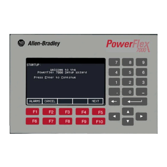
Everything is user friendly about the PowerFlex 7000 operator interface terminal including the greeting on the opening screen. The terminal is designed for the greatest ease of use for start-up, monitoring and troubleshooting. -
Page 23: Chapter 2 Drive Installation
Failure to do so may result in personal injury and/or equipment damage. General Handling Procedures Refer to “General Handling Procedures for PowerFlex 7000 Medium Voltage Drives”, publication no. 7000-IN002_-EN-P supplied in the drive shipment (affixed to the drive). Additional copies can be ordered through your local Rockwell Automation Sales office. -
Page 24: Siting Of The Drive
Drive Installation Siting of the Drive Site Considerations The standard environment in which the equipment is designed to operate is: • Elevation above sea level less than 1000 meters (3250 feet) • Ambient air temperature between 0°C (32°F) and 40°C (104°F) •... - Page 25 The topology utilized in the PowerFlex 7000 medium voltage AC drive does not produce dv/dt or peak voltage problems, and has been tested with motors located up to 15 kilometers from the drive.
-
Page 26: Installation
Drive Installation Installation When the drive has been placed at its installation area, the lag bolts that fasten the shipping skid to the drive must be removed. The drive is moved off the shipping skid and the shipping skid can be discarded. - Page 27 Drive Installation Flat plate (Quantity = 1) Exhaust hood panels (Quantity = 2) M6 thread forming screws (Quantity = 20) Figure 2.1 – Fan Hood Assembly All the components are shipped assembled. Figure 2.2 – Acoustic Fan Hood Assembly 7000 “A” Frame 7000A-UM151E-EN-P - October 2018...
- Page 28 Drive Installation Installation (cont.) Locate the exhaust hood on top of the cabinet per Figure 2.3 and re- install the original cover plate previously set aside. (Care must be taken that the notches on the bottom flange are oriented toward the sides of the drive).
- Page 29 Drive Installation Assembled Acoustic Exhaust Hood Top Plate for Converter and Common Mode Choke/ M6 Screw. DC Link Cabinet Remove Existing Screw and reinsert with Hood. (Quantity = 11) Figure 2.4 – Acoustic Fan Hood Installation 7000 “A” Frame 7000A-UM151E-EN-P - October 2018...
-
Page 30: Installation Of Integral Transformer Cooling Fan
Drive Installation Installation (cont.) Installation of Integral Transformer Cooling Fan 1. Remove the protective plate covering the fan opening on the top of Isolation Transformer cabinet and discard. 2. Locate the cooling fan on top of the cabinet. Position it over the opening and align the mounting holes and wire harness connections. -
Page 31: Neutral Resistor Assembly
Drive Installation Neutral Resistor Assembly Top Plate for Neutral Resistor Housing Ground Resistor Hood here 900 mm Converter – Top Plate for Converter 800 mm Common Mode Choke Cabinet and Common Mode Choke Cabinet Neutral Resistor Assembly Attach ground to top plate Refer to Electrical Drawings to verify cable rating to connect neutral... -
Page 32: Installation Of Neutral Resistor Assembly
2-10 Drive Installation Assembled Acoustic Exhaust Hood Hood Ground Stud M6 Screw. Remove existing screw and reinsert with Hood. (Quantity = 11) M6 Screw (Quantity = 6) Ground Exhaust Hood here. (Use Green M6 Screw) Top Plate for Converter and Common Mode Choke/DC Link Cabinet Neutral Resistor Assembly Figure 2.7 –... -
Page 33: Cabinet Layout And Dimensional Drawings Of Drive
Drive Installation 2-11 Cabinet Layout and The following dimension drawing is a sample and may not accurately detail your drive. It is provided here to give you a general overview Dimensional Drawings of a typical drive. of Drive The Dimensional Drawings are order specific and will show the information outlined. -
Page 34: Powerflex 7000 "A" Frame Dimensional Drawing
2-12 Drive Installation PowerFlex 7000 “A” Frame Dimensional Drawing SAMPLE Note: Contact Factory for Seismic Mounting Information. 7000A-UM151E-EN-P - October 2018 7000 “A” Frame... -
Page 35: Drive Layout
Drive Installation 2-13 Drive Layout The following diagrams are presented to show the typical layout of the three main configurations of the PowerFlex 7000 “A” Frame Drive. Configuration #1 Direct-to-Drive (AFE with DTC DC Link) Converter Cabinet Control/DC Link/Fan Cabinet... -
Page 36: Afe Rectifier (Separate Isol. Transformer (Config. #2)
2-14 Drive Installation Configuration #2 AFE Rectifier (Separate Isolation Transformer) Cabling Cabinet Converter Cabinet Control/DC Link/Fan Cabinet Figure 2.9 – AFE Rectifier (Separate Isolation Transformer) 7000A-UM151E-EN-P - October 2018 7000 “A” Frame... -
Page 37: Afe Rectifier (Integral Isol. Transformer (Config. #3)
Drive Installation 2-15 Configuration #3 AFE Rectifier (Integral Isolation Transformer) Isolation Transformer Converter Cabinet Control/DC Link/Fan Cabinet and Cabling Catinet Figure 2.10 – AFE Rectifier (Integral Isolation Transformer) 7000 “A” Frame 7000A-UM151E-EN-P - October 2018... -
Page 38: Cabling Cabinet #1 (With Input Starters)
2-16 Drive Installation Cabling Cabinet #1 The cabling cabinet of the drive with integral line reactor and input starter is located in the left-hand section. The mounting and location of the line reactor and input starter are shown along with customer cable termination locations. -
Page 39: Cabling Cabinet #1 (Without Input Starters)
Drive Installation 2-17 Cabling Cabinet #1 Low Voltage Compartment Line Cable Terminations Hall Effect Sensors Current Transformers Control Power Transformer Fuses Motor Cable Terminations AC Line Reactor Figure 2.12 – Cabling Cabinet for Configuration #1 without Input Starters 7000 “A” Frame 7000A-UM151E-EN-P - October 2018... -
Page 40: Cabling Cabinet #2
2-18 Drive Installation Cabling Cabinet #2 Cabling cabinet #2 is located in the left hand section and shows the medium voltage area for customer cable terminations, three phase fan power transformer, and fuse assemblies for transformer. Low Voltage Wireway Current Transformer Hall Effect Sensor Motor Cable Terminations Line Terminals... -
Page 41: Cabling Cabinet #3
Drive Installation 2-19 Cabling Cabinet #3 The cabling cabinet of the drive with integral isolation transformer is located in the left-hand section. The mounting and location of the isolation transformer is shown along with customer cable termination locations. The cooling fan for the isolation transformer is located on top. Fan Housing Top Cable Entry and Exit locations... -
Page 42: Converter Cabinet
2-20 Drive Installation Converter Cabinet The converter cabinet for all configurations of the PowerFlex 7000 “A” Frame drive is located in the middle section. The mounting and location of Inverter / rectifier modules are shown along with gate drive power supplies and voltage sensing modules. -
Page 43: Control/Dc Link/Fan Cabinet
The control / DC link / fan cabinet for all configurations of the Cabinet PowerFlex 7000 “A” Frame drive is located in the right section. The mounting and location of the DC link inductor, line / load side capacitors, and main cooling fan are shown behind the low voltage control tub. -
Page 44: Low Voltage Control Tub
Component Definition and Maintenance, for complete content details Fan Cabinet) of the low voltage section. Note: The low voltage control tub has the same layout for all PowerFlex 7000 “A” Frame drive ratings. AC to DC Pioneer Power Supply Analog... - Page 45 Drive Installation 2-23 AC to DC Cosel Power Supply Analog Fiber Optic Control Interface Board Boards Drive Processor Module Board DC to DC Power Supply Hinged Panel (Closed) Hinged Panel (Open) Figure 2.18 – Location of Low Voltage Control Tub (Cosel Power Supply) 7000 “A”...
-
Page 46: Iec Component And Device Designations
(American National Standards Institute) standards. The symbols used to identify components on the drawings are international and a full listing of the symbols is given as part of each PowerFlex 7000 electrical drawing (ED) set. The device designations used on the drawings and labeling are also listed with explanations on each drawing set. -
Page 47: Cable Insulation
Drive Installation 2-25 Cable Insulation The cable insulation requirements for the PowerFlex 7000 “A” Frame drive are given in the tables below. Voltage ratings shown in the following A T T E N T I O N A T T E N T I O N tables are peak line-to-ground. -
Page 48: Wire Group Numbers
Belden 9463 - 24 AWG, twisted pair, shielded Note 1: Steel conduit or cable tray may be used for all PowerFlex 7000 “A” Frame Drive power or control wiring, and steel conduit is required for all PowerFlex 7000 “A” Frame Drive signal wiring. All input and output power wiring, control wiring or conduit should be brought through the drive conduit entry holes of the enclosure. -
Page 49: To Access The Customer Power Cable Terminations
Drive Installation 2-27 The wire sizes must be selected individually, observing all applicable safety and CEC, IEC or NEC regulations. The minimum permissible wire size does not necessarily result in the best operating economy. The minimum recommended size for the wires between the drive and the motor is the same as that used with an across-the-line starter. -
Page 50: Power Connections
2-28 Drive Installation Power Connections The installer must ensure that interlocking with the upstream power source has been installed and is functioning. The installer is responsible for ensuring that power connections are made to the equipment in accordance with local electrical codes. The drive is supplied with provision for cable lugs. - Page 51 Drive Installation 2-29 411.9 [16.22] 284.9 [11.22] 157.9 [6.22] 242.5 [9.55] Note: Cable Entry Location To access line cables, (Top Load/Motor Entry) fan housing and assembly must first be removed. 700.0 Line Cables [27.56] L1, L2, L3 L1, L2, L3 190.6 [7.50] Top Cable Entry...
- Page 52 2-30 Drive Installation Power Connections (cont.) Cable Entry Location Cable Entry Location (Top) (Top) 1000 [39.4] 1000 [39.4] 700.00 700.00 [27.56] [27.56] 209.6 209.6 [8.25] [8.25] 480.5 [18.92] 480.5 [18.92] 480.5 480.5 366.2 [14.42] 366.2 [14.42] [18.92] [18.92] 1133.0 1133.0 251.9 [9.92] 251.9 [9.92] [44.61]...
- Page 53 Drive Installation 2-31 400.0 [15.75] 400.0 [15.75] 1000.3 [39.38] 1000.3 [39.38] 112.8 [4.44] 112.8 [4.44] 112.8 112.8 [4.44] [4.44] 2314.6 2314.6 [91.12] [91.12] 1409.4 1409.4 [55.49] [55.49] 1180.8 1180.8 [46.49] [46.49] 952.2 952.2 [37.49] [37.49] 412.9 [16.26] 412.9 [16.26] SECTION A-A SECTION A-A Figure 2.21 –...
-
Page 54: Cabling Cabinet For Config. #3
2-32 Drive Installation Power Connections (cont.) 1000.4 [39.39] 700.0 [27.56] 157.9 [6.22] 157.9 [6.22] 731.4 [28.79] 328.3 [12.92] 1998.0 [78.66] 2314.6 1890.0 [91.12] [74.41] 1782.0 [70.16] Figure 2.22 – Dimension Views of Cabling Cabinet for Configuration #3 7000A-UM151E-EN-P - October 2018 7000 “A”... -
Page 55: Power And Control Wiring
Drive Installation 2-33 Power and Control Wiring Drive line-ups (i.e. Drive and Input Starter) which are delivered in two or more sections, for ease of handling, will require that the power and control wiring be re-connected. After the sections are brought together, the power and control wiring is to be re-connected as per the schematic drawings provided. -
Page 56: Grounding Practices
2-34 Drive Installation Grounding Practices The purpose of grounding is to: • provide for the safety of personnel • limit dangerous voltages on exposed parts with respect to ground • facilitate proper over current device operation under ground fault conditions, and •... -
Page 57: Grounding Guidelines And Practices For Drive Signal And Safety Grounds
Drive Installation 2-35 Each power feeder from the substation transformer to the drive must be provided with properly sized ground cables. Utilizing the conduit or cable armor as a ground is not adequate. Note that if a drive isolation transformer is used, the WYE secondary neutral point should not be grounded. -
Page 58: Customer And Power Integrators
2-36 Drive Installation Grounding Practices (cont.) Grounding Requirements and Grounding Specification for Customers and Power Integrators An external ground must be attached to the main ground bus. The grounding means must comply with applicable local codes and standards. As general guidelines, for information only, the ground path must be of sufficiently low impedance and capacity that: •... -
Page 59: Interlocking
Drive Installation 2-37 Interlocking Access to the medium voltage areas of the drive is restricted by the use of key interlocking for safety. At installation the key interlocking is set up so that access to the medium voltage compartments of the equipment can only be made when the upstream power is locked in the off position. - Page 60 2-38 Drive Installation 7000A-UM151E-EN-P - October 2018 7000 “A” Frame...
-
Page 61: Terminology
The chapter deals only with the operation of the operator interface. Specific references to a particular parameter are only for illustrative purposes. Refer to PowerFlex 7000 Medium Voltage AC Drive • Technical Data (Publication 7000-TD002_-EN-P) for information about the actual 'tags' within the drive and their use. - Page 62 Operator Interface PowerFlex Operator interface – References to the operator interface refer to the product consisting of the PanelView 550 interface hardware and the unique software contained within it, which allows it to function with the Medium Voltage Drive. Editing Field – An area of a screen that is displayed in reverse video.
-
Page 63: Overview
Operator Interface Overview The operator interface used on the PowerFlex 7000 Medium Voltage Drive is that of the PanelView 550 terminal (Figure 3.1). This terminal however does not behave as a PanelView, as only the hardware for the operator interface has been utilized. The... -
Page 64: Cursor (Selection) Keys
Operator Interface Even though the upper row of Softkeys (i.e. F1-F5) may not be shown on some displays, the F1-HELP key is always active. (F2-F5) are only active if shown. Cursor (Selection) Keys The cursor keys are normally used to select an item on the display. When an item on the display is selected, that item will be displayed in reverse video. -
Page 65: What Is A Screen
Operator Interface While entering a value, the value may be edited using the [backspace] key. This key will remove the right most digit (or decimal point or negative). The help screen uses the backspace key to return to the previous level of help. The enter key varies depending on the screen. -
Page 66: Information Windows
Operator Interface The upper left-hand corner contains the name of the screen (i.e. SELECT GROUP:). Knowing the name of the screen will assist you in the orientation of the menu system. On some screens to the right of the screen name, will be the name of the selected item from the previous screen as shown in Figure 3.3. -
Page 67: Accessing/Writing To Drive
Operator Interface Accessing/Writing to Drive When first powered up, the operator interface knows very little about the information in the drive. As each screen is activated, the operator interface requests information from the drive, which it will store within the operator interface for future reference. When the operator interface requests information from the drive, a window is used to display a message "Accessing Drive ...". -
Page 68: Language Changing
Operator Interface Figure 3.4 – Communications Error Figure 3.5 – Communications Error Language Changing When the language used by the drive changes, (either via the operator interface or an external device), the operator interface must do considerable work. The database strings are all invalidated, the character set for the server is changed and all strings used by the operator interface are linked to the new language. -
Page 69: Operator Interface Power-Up Sequence
Operator Interface F1 - Help This operation is active on every screen, even if the 'Softkey' is not displayed. Help is context sensitive and will display help that relates to the screen that you are currently viewing. F6 - Alarms The F6 'Softkey' will always get you to the Alarm Summary Screen. - Page 70 3-10 Operator Interface b) Obtaining Drive Database - During this phase, the database of information about the drive is obtained from the drive. Obtaining the database at this point in time is optional and may be aborted by pressing any key on the operator interface. Obtaining the entire database does however speed up subsequent operations since relevant portions of the database do not have to be obtained.
-
Page 71: Top Level Menu
Operator Interface 3-11 Top Level Menu This screen (Figure 3.6) represents the main menu from which all other screens (and the operations which they perform) are activated. To activate an operation, simply press the function key corresponding to the 'Softkey' shown on the screen. A screen for that operation will be displayed. -
Page 72: How To
3-12 Operator Interface How To: The following sections describe how to perform the various operations on the drive, using the operator interface. Throughout the discussion, a number of screens will be used to achieve the desired operation. In many cases, the same screen will be used for more than one operation, however with possibly different data from the drive. -
Page 73: Help On Help
Operator Interface 3-13 The help for the additional topic will be displayed as in Figure 3.8 . As with the original help screen, the related topic help may also have related topics. Press the [backspace] key to return to the previous level of help, (i.e. the previous related topic). -
Page 74: Modify Operator Interface Operation (Utility)
3-14 Operator Interface Modify Operator Interface The utility operation of screens change the characteristics of Operation (Utility) the operator interface. Within this operation you will: Set the clock and calendar Change the delay for the display backlight shutoff ... -
Page 75: Changing Contrast
Operator Interface 3-15 To change the duration of the delay, press the [F2] key. The current backlight delay will be shown in reverse video (Figure 3.11). The value can be adjusted from 0 to 60 minutes. A value of zero (0) will disable the delay, keeping the light on indefinitely. -
Page 76: Setting Time
3-16 Operator Interface Figure 3.12 – Utility Contrast Setting Time The clock setting controls the time stamp that the drive uses on the information contained on the alarm summary screen. To change the time, press the [F5] key. The hour’s position of the clock will be in reverse video (Figure 3.13). -
Page 77: Setting Date
Operator Interface 3-17 Setting Date The calendar setting controls the date stamp that the drive uses on the information contained on the alarm summary screen. To change the date, press the [F4] key. The year position of the calendar will be in reverse video (Figure 3.14). - Page 78 3-18 Operator Interface Figure 3.15 – Utility Meter To change the tag attach to a meter, use the [cursor up] and [cursor down] keys to highlight the desired meter and press the [enter] key. (If nothing happens then you have not gained the required access to make changes.) Press the [F8] key in order to gain access and refer to the section entitled Enter/Modify an Access Level .
- Page 79 Operator Interface 3-19 The first character position of the string will be in reverse video as shown in Figure 3.17. Refer to the section entitled "Edit Text". Figure 3.17 – Edit the Text When editing is complete, the screen will appear as in Figure 3.18. Figure 3.18 –...
-
Page 80: Viewing Revision Levels
3-20 Operator Interface Figure 3.19 – Top Level Meter Modified Viewing Revision Levels For the purpose of maintenance or upgrading of software, the revision levels of all the software contained in the terminal and the drive may be viewed. To access this screen, press the [F9] key. A screen typical of Figure 3.20 shows: –... -
Page 81: Transfer Data In Memory
Operator Interface 3-21 A screen typical of Figure 3.21 will be displayed. To modify the text refer to the section entitled "Edit Text", noting the following exception. When the text has been entered (as in Figure 3.22) the enter key has no effect. Simply press the exit key [F10] to accept the edited string. -
Page 82: Picking An Access Level
3-22 Operator Interface Picking an Access Level Access Levels are used in the drive to protect parameters from unauthorized changes and to filter out the amount of information viewed. Each access level takes on the parameters and permissions of the lower access levels. The default access level is 'Monitor'. -
Page 83: Via Name
Operator Interface 3-23 than one page of groups exist, press the [F8] and [F9] keys to view the other pages. Press the [cursor up] or [cursor down] keys to select the desired group, (i.e. reverse video the group name). Press the [enter] key. The SELECT screen (Figure 3.24) is displayed showing the members of the selected group. - Page 84 3-24 Operator Interface Selecting via a name is initiated from the SELECT GROUP screen (Figure 3.23) by pressing the [F7] key. This displays the SELECT LETTER screen shown in Figure 3.25. Using the cursor keys, select (i.e. reverse video) the letter with which the desired tag starts with.
-
Page 85: Via Code
Operator Interface 3-25 From the SELECT LETTER screen (Figure 3.25) the tag may also be selected via a code by pressing the [F5] key. Via Code This method of selecting a tag is initiated from the SELECT LETTER screen (Figure 3.25) by pressing the [F5] key. It allows you to select the tag, given that you know the tag code associated with the desired tag. -
Page 86: Edit Text
3-26 Operator Interface Figure 3.28 – Valid Tag Code Figure 3.29 – Invalid Tag Code When the [enter] key is pressed for a valid tag code (i.e. Figure 3.28) the selected tag will be used to continue the operation for which the selection process was being used if that tag is appropriate for the operation. - Page 87 Operator Interface 3-27 The operator interface's keypad does not contain any alpha keys to allow direct input of the characters. This section will describe the operation for which characters may be entered. Figure 3.31 – Typical Text Edit Screen The screen shown in Figure 3.31 is typical of all screens using the edit text operation.
-
Page 88: Configure The Drive
3-28 Operator Interface To abort the changes to the string being edited press the [backspace] key. This will restore the string to its contents when the screen was first entered. The editing operation is completed by pressing the [enter] key. Changes are not permanently made until the screen is exited via the [F10] key. - Page 89 Operator Interface 3-29 associated with Access Levels. Each Access Level, (except for the first one 'Monitor') has its own password number (PIN). These values can be unique or all can be set to the same value. The default level, 'Monitor' does not have a PIN associated with it. With this Access Level, the drive configuration can be viewed, but no changes are allowed to the parameters.
- Page 90 3-30 Operator Interface Figure 3.33 – Pin Entry The value may be edited by using the [backspace] key. When the value has been typed in, press the [enter] key. If the correct PIN was entered, the access level of the operator interface will change as shown in Figure 3.34 .
- Page 91 Operator Interface 3-31 Figure 3.35 – PIN Change Enter the current PIN value via the data keys [0]-[9] and press the [enter] key. As in the ACCESS screen, the entered value is shown via placeholders and may be edited with the [backspace] key. If you entered the correct PIN, the screen now asks you for the new PIN.
- Page 92 3-32 Operator Interface Figure 3.37 – Invalid PIN Figure 3.38 – Invalid PIN Verification If you were not successful in changing the password, simply start over again by typing in the current password value. 7000A-UM151E-EN-P - October 2018 7000 “A” Frame...
-
Page 93: Drive Setup
Operator Interface 3-33 Drive Setup This section describes how to: • select an alternate language • enter data to a drive parameter • assign a tag to an analog port • enable and disable a fault via a mask • assign text to be associated with optional external fault inputs •... -
Page 94: Language Selection
3-34 Operator Interface Figure 3.40 – Basic Access Level Language Selection The drive is capable of supporting multiple languages. The operator interface supports these languages via language modules which must initially be loaded via the flash card (refer to the section Flash Memory Transfers). -
Page 95: Modify Parameters
Operator Interface 3-35 Modify Parameters To change a parameter, Use the up/down arrow keys on the SETUP screen to select the 'Parameters' option and press the [enter] key. This will begin the selection process of a parameter as described in the section entitled "Select a Parameter". - Page 96 3-36 Operator Interface Figure 3.43 – Modify Numerical Value To be allowed to make changes to the parameter, the operator interface must be set to an Access Level other than 'Monitor'. (You will be able to view the screen; however, pressing the data entry keys will have no effect).
-
Page 97: Enumerated Value
Operator Interface 3-37 Enumerated Value When the parameter is an enumerated value, the MODIFY PARAMETER screen typical of Figure 3.44 will be displayed. This screen shows: • the name of the parameter for which you are make the changes (i.e. Operating Mode) •... - Page 98 3-38 Operator Interface options exist then what can be displayed on a single screen, a triangle or inverted triangle symbol will indicate in which direction the list can be expanded (Figure 3.46). Use the up/down cursor keys to scroll onto these additional options. Press the [enter] key to accept the new value as shown in Figure 3.47.
-
Page 99: Bit Encoded Value
Operator Interface 3-39 Bit Encoded Value When the parameter is a bit encoded value, the MODIFY PARAMETER screen typical of Figure 3.48 will be displayed. This screen shows: • the name of the parameter for which you are make the changes (i.e. -
Page 100: Analog Ports
3-40 Operator Interface Analog Ports The drive contains a number of external analog ports to which you can assign any parameter. To setup an analog port, use the up/down arrow keys on the SETUP screen to select the 'Analog' option and press the [enter] key. -
Page 101: Fault Masks
Operator Interface 3-41 Figure 3.49 – Analog Setup This will begin the selection process of a tag as described in the section entitled "Select a Parameter". When you have completed the selection process, the selected tag will be assigned to the port. To remove an assignment to the highlighted port, press the [delete] (Backspace) key. - Page 102 3-42 Operator Interface Figure 3.51 – Fault Mask OFF Figures 3.50 and 3.51 show all fault masks regardless of their current state. The fault masks can be viewed according to their state by pressing the [F7] key on the FAULTS SETUP screen. This will display the FAULTS OVERVIEW screen, typical of Figures 3.52 and 3.53.
- Page 103 Operator Interface 3-43 state of fault masks currently displayed, press the [F7]. Each press of the [F7] key will toggle the screen to show the masks in the other state. To change the state of a mask on the FAULTS OVERVIEW screen, use the [cursor up] and [cursor down] keys to select the desired mask and press the [enter] key.
-
Page 104: User Definable External Text
3-44 Operator Interface Figure 3.56 – AC O/V Mask is ON User Definable External Text The drive contains a number of external fault inputs. You can custom define the text associated with these inputs, which will be used on the alarm screen and the fault mask screens. To define the text, use the up/down arrow keys on the SETUP screen to select the 'External Text' option and press the [enter] key. -
Page 105: Plc
Operator Interface 3-45 Figure 3.58 – Modify Text Figure 3.59 – Modification Completed The changes made do not take affect until you press [F10] and exit the screen. Any time prior to this you may cancel all of the changes made after coming to the screen by pressing the [F7] key. - Page 106 3-46 Operator Interface The layout of the PLC 'rack' is dependent on the DIP switch settings on the RIO adapter, (refer to the appropriate manual for information on the following adapters and their use: 1203-GD1, 1203-GK1, 1203-CN1, 1203-GD2, 1203-GK2, 1203-GK5, 1203-GU6, 1203- SM1 and 1203-SSS).
-
Page 107: Xio
Operator Interface 3-47 The changes made do not take affect until you press [F10] and exit the screen. Any time prior to this you may cancel all of the changes made after coming to the screen by pressing the [F7] key. The drive uses XIO adapters to hardwire to discrete inputs and outputs. -
Page 108: Store/Retrieve Configuration (Nvram)
3-48 Operator Interface Figure 3.62 – Message Prompt Screen Figure 3.63 – NVRAM Screen Store/Retrieve Configuration (NVRAM) To access the memory functions, press [F5] on the Top Level Menu. Within this screen it is possible to perform three operations on the memory of the drive. -
Page 109: Save
Operator Interface 3-49 Save The changes that you have made to the drive data must be saved if you do not want to lose the data when the drive is powered off. To save the changes, press the [F5] key (Figure 3.65). Figure 3.65 –... -
Page 110: Display Parameters
3-50 Operator Interface Display Parameters The parameters of the drive can be displayed, continually showing the value contained in the drive. From the Top Level Menu, press the [F4] key. The DISPLAY GROUP screen of Figure 3.67 is displayed. The screen shows one or more pages of groups that can be displayed. The number of groups displayed depends on the current access level. -
Page 111: Custom Group
Operator Interface 3-51 Figure 3.70 – Bit Description for Local Outputs The DISPLAY screen, typical of Figure 3.68, is displayed. The screen shows the name of the group being displayed to the right of the screen name (“FEATURE SELECT”). One or more pages of the members in the group are displayed along with the value for this tag in the drive and its unit of measurement. - Page 112 3-52 Operator Interface To assign a tag to the display, use the [cursor up] and [cursor down] keys to highlight the desired item position and press the [enter] key. This will begin the selection process of a tag as described in the section entitled "Select a Parameter".
-
Page 113: View Drive Status
Operator Interface 3-53 View Drive Status The status of the drive is viewed by pressing the [F7] key from the Top Level Menu. This screen, shown in Figure 3.73, constantly displays the latest status of the drive. Figure 3.73 – Status Screen View and Reset Alarms All drive faults and warnings are logged to their respective queues. -
Page 114: Help For Alarms
3-54 Operator Interface To reset the drive, press the [F7] key. This operation will reset any latched faults in the drive. This has no action upon either the Fault or Warning queues. If some faults still exist, they will return as new faults. Faults and Warnings are stored into separate queues. -
Page 115: Request Printouts
Operator Interface 3-55 Figure 3.76 – Alarm Help Figure 3.77 – No Alarm Help Request Printouts When the drive contains the optional printer, you can obtain hard copies of the data that you are able to view on the terminal. The printouts are requested from the PRINTER screen. -
Page 116: Loading Programs (Firmware)
3-56 Operator Interface Figure 3.78 – Typical Printer Screen Loading Programs Firmware is the program that is run in the operator interface to (Firmware) provide all the functionality described in this manual. Firmware is loaded from the flash card in one of two ways. a) If an operator interface has a memory card inserted when it is powered up or rebooted, and that card has a valid firmware file with the extension of .FMW, the operator interface will... - Page 117 Operator Interface 3-57 Figure 3.79 – Load New Firmware The screen will then ask you to confirm the operation. Press the [F8] key to proceed, or the [F9] key to abort. Performing a DOWNLOAD FIRMWARE operation will overwrite the existing firmware that is currently running.
-
Page 118: Parameter Transfers
3-58 Operator Interface memory card containing a firmware file in the operator interface, after the firmware has been downloaded. Parameter Transfers The parameters used by the drive are stored within the drive itself. The operator interface is used to review and modify these parameters. When a Drive Control Board is changed, it is necessary to re-enter the parameters into the new board. -
Page 119: Upload To Operator Interface
Operator Interface 3-59 Upload to Operator Interface The parameters are read from the drive and stored in the operator interface by pressing the [F5] key. The screen will appear as in Figure 3.81, indicating the operation you are about to perform. The screen will then ask you to confirm the operation. -
Page 120: Upload To Memory Card
3-60 Operator Interface Upload to Memory Card The parameters are read from the drive and stored on a memory card by pressing the [F4] key. The operator interface will enter the DIRECTORY screen in which a parameter filename can be entered. Refer to the section entitled “Enter a filename”. -
Page 121: Parameter File Format
Operator Interface 3-61 The screen will then ask you to confirm the operation. Press the [F8] key to proceed, or the [F9] key to abort. Pressing the [F4] key may restart an aborted transfer or one that failed. To select or enter a different filename, press the [F7] key. -
Page 122: Loading Language Modules
3-62 Operator Interface Loading Language Modules In order to use a language in the operator interface, it must first be loaded into the operator interface from the flash card. From the TRANSFER screen, press the [F5] key. The operator interface will enter the DIRECTORY screen, from which an existing language module filename can be selected or entered, Figure 3.83. -
Page 123: System Programming
Operator Interface 3-63 In order to download a newer version of a language, all languages in the operator interface must first be cleared (this is a characteristic of flash memory) by pressing the [F2] key on the TRANSFER:LANGUAGE screen. The screen as in Figure 3.85 will then ask you to confirm the operation. -
Page 124: Operator Interface (Cont.)
3-64 Operator Interface Operator Interface Menu The screens of the operator interface are used to form a menu driven system to access the various operations in the drive. The hierarchy Hierarchy Chart of this menu system is shown in Figures 3.86 and 3.87. What does it show? The chart shows the relationship between screens and a particular operation. -
Page 125: Example
Operator Interface 3-65 Example As an example of using the chart, we will modify a parameter while displaying it, starting from the Top Level Menu referred to in the chart as the MAINMENU screen. This example assumes you have read the previous sections of this manual. The example will concentrate more on the flow of screens and how it relates to the chart, rather then the actual operations being performed by each screen. - Page 126 3-66 Operator Interface Figure 3.86 – Menu Hierarchy 7000A-UM151E-EN-P - October 2018 7000 “A” Frame...
- Page 127 Operator Interface 3-67 Figure 3.87 – Menu Hierarchy 7000 “A” Frame 7000A-UM151E-EN-P - October 2018...
-
Page 128: Pcmcia Memory Card Installation Data Description
Installation Data The memory card slides into the card slot located on the backside of the PowerFlex 7000 drive operator interface. These instructions show how to insert the card in the Operator interface. The memory card should be kept free from... - Page 129 Operator Interface 3-69 2. Position the card vertically so the key slot is facing the right side of the operator interface. KEY SLOT Figure 3.89 – Key Slot Orientation 3. Insert the card into the card slot and push until the card is firmly seated.
- Page 130 3-70 Operator Interface Notes: 7000A-UM151E-EN-P - October 2018 7000 “A” Frame...
- Page 131 Chapter Component Definition and Maintenance Cabling Cabinet Components Low Voltage Compartment Line Cable Terminations Hall Effect Sensors Current Transformers Control Power Transformer Fuses Motor Cable Terminations AC Line Reactor Figure 4.1 – Cabling Cabinet for Configuration #1 (Direct-to-Drive) 7000 “A” Frame 7000A-UM151E-EN-P - October 2018...
- Page 132 Component Definition and Maintenance Line Cable Terminations (behind Disconnect Switch) Fused Disconnect Switch Disconnect Switch Operating Handle Vacuum Contactor Assembly Control Power Transformer Control Power Transformer Fuses Motor Cable Terminations (Hall Effect Sensors behind) AC Line Reactor Figure 4.2 – Cabling Cabinet for Configuration #1 (Direct-to-Drive, optional input starter shown) 7000A-UM151E-EN-P - October 2018 7000 “A”...
-
Page 133: (Afe Rectifier With Separate Isolation Transformer)
Component Definition and Maintenance Low Voltage Wireway Current Transformer Hall Effect Sensor Motor Cable Terminations Line Terminals Hall Effect Sensor Current Transformer Fan Control Power Transformer Control Power Transformer Fuses Figure 4.3 – Cabling Cabinet for Configuration #2 (AFE Rectifier with Separate Isolation Transformer) 7000 “A”... -
Page 134: (Afe Rectifier With Integral Isolation Transformer)
Component Definition and Maintenance Fan Housing Top Cable Entry and Exit locations Ground Bus Hall Effect Sensors Line Terminals Load Terminals Current Transformers (CT) Integral Isolation Transformer Bottom Cable Entry Side View Front View and Exit locations Figure 4.4 –Cabling Cabinet for Configuration #3 (AFE Rectifier with Integral Isolation Transformer) 7000A-UM151E-EN-P - October 2018 7000 “A”... -
Page 135: Converter Cabinet Components
Component Definition and Maintenance Converter Cabinet Components Inverter Modules Isolated Gate Drive Power Supplies (IGDPS) Rectifier Modules Voltage Sensing Boards Figure 4.5 – Converter Cabinet Components (3300/4160 V version) 7000 “A” Frame 7000A-UM151E-EN-P - October 2018... -
Page 136: Converter Cabinet
Component Definition and Maintenance Converter Cabinet The converter cabinet contains three rectifier modules and three inverter modules. Figure 4.5 shows a 3300/4160 V converter with a PWM Rectifier. Isolated Gate Driver Power Supplies (IGDPS) are mounted on the cabinet’s right side sheet (6600 V, 2400 V Drives) and on the cabinet’s left side sheet (3300 V, 4160 V Drives). -
Page 137: Operation
Component Definition and Maintenance Drive input power from line terminals Heavy duty distribution class surge arrester Figure 4.6 – Surge Arresters Operation The operation of arresters without a gap is the same as that of MOVs. Depending on design, the arrester may also be gapped. Both gapped and un- gapped arresters provide adequate overvoltage protection. -
Page 138: Powercage
Component Definition and Maintenance PowerCage™ A PowerCage is a converter module, consisting of the following elements: • epoxy resin housing • power semi-conductors with gate driver circuit boards • heatsinks • clamp • snubber resistors • snubber capacitors • sharing resistors Each drive consists of three PowerCage rectifier modules and three PowerCage inverter modules. - Page 139 Component Definition and Maintenance The SGCT circuit board is sensitive to static A T T E N T I O N A T T E N T I O N charges. It is important that these boards should not be handled without proper grounding. Some circuit boards can be destroyed by static A T T E N T I O N A T T E N T I O N...
- Page 140 4-10 Component Definition and Maintenance PowerCage™ (cont.) Matched set Matched set Clamp Base 2 SGCTs 2 SGCTs Heatsink Temperature Clamp head Module housing Feedback Board Figure 4.8 – 4-Device PowerCage Matched set Matched set Heatsink Clamp Base 3 SGCTs 3 SGCTs Clamp head Module housing Temperature...
-
Page 141: Sgct And Snubber Circuit
Component Definition and Maintenance 4-11 SGCT and Snubber Circuit As with all power semi-conductor or thyristors, the SGCT must have a snubber circuit. The snubber circuit for the SGCT is comprised of a snubber resistor in series with a snubber capacitor. SHARING RESISTOR SNUBBER... -
Page 142: Uniform Clamping Pressure
4-12 Component Definition and Maintenance SGCT Device Diameter Clamp Force 400 A SGCT 38 mm 8.6 kN 800 A SGCT 47 mm 13.5 kN 1500 A SGCT 63 mm 20 kN Pressure on the SGCTs must be uniform to prevent damage and to ensure low thermal resistance. -
Page 143: Checking Clamping Pressure
Component Definition and Maintenance 4-13 Checking Clamping Pressure Periodically, the clamping force in the PowerCage should be inspected. Ensure there is no power to the equipment. To prevent electrical shock, ensure the main A T T E N T I O N A T T E N T I O N power has been disconnected before working on the drive. -
Page 144: Temperature Sensing
4-14 Component Definition and Maintenance Never rotate the calibration nut located outside I M P O R T A N T I M P O R T A N T the indicating washer at the end of the threaded rod. The rotation of the outer nut will affect the torque calibration, which is factory set. -
Page 145: Symmetrical Gate Commutated Thyristor Replacement
Component Definition and Maintenance 4-15 Symmetrical Gate The Symmetrical Gate Commutated Thyristor (SGCT or device) with Commutated Thyristor attached circuit board is located within the PowerCage assembly. Replacement SGCTs must be replaced in matched sets: • 3300V and 4160V systems use sets of 2 •... - Page 146 4-16 Component Definition and Maintenance Symmetrical Gate 1. Ensure there is no power to the equipment. Commutated Thyristor Replacement (cont.) To prevent electrical shock, ensure the main A T T E N T I O N A T T E N T I O N power has been disconnected before working on the drive.
- Page 147 Component Definition and Maintenance 4-17 7. Clean the heatsink with a soft cloth and rubbing alcohol. 8. While grounded, remove the SGCT from the anti-static bag it is supplied in. 9. Apply a thin layer of Electrical Joint Compound (Alcoa EJC No. 2 or approved equivalent) to the contact faces of the new SGCTs to be installed.
-
Page 148: Snubber Resistors
4-18 Component Definition and Maintenance Snubber Resistors Snubber resistors are connected in series with the snubber capacitors. Together they form a simple RC snubber that is connected across each thyristor (SGCT). The purpose of the snubber circuit is to reduce the voltage stress (dv/dt and peak) on the thyristors and to reduce the switching losses. -
Page 149: Fiber Optic Cabling
Component Definition and Maintenance 4-19 Fiber Optic Cabling The equipment is provided with fiber optic cabling as a means of interfacing the low voltage control to the medium voltage circuits. The user of the equipment should never need to change the routing of the fiber optic cables. -
Page 150: Dc Link/Fan/Control Components
4-20 Component Definition and Maintenance D.C. Link / Fan / Control Components Low voltage Control Tub Retaining Hardware AC/DC Power Supply Inlet Ring DC Link Inductor M+ L+ L- M- Analog Drive Control Board Grounding Network/ Filter Motor Filter Capacitor Medium Voltage Barrier (for access to... -
Page 151: Filter Capacitors
Component Definition and Maintenance 4-21 Filter Capacitors Filter capacitors are used on the motor side for all drives. The AFE rectifier option also includes filter capacitors on the line side. Refer to Figure 4.17 (DC Link and Fan Cabinet with control panel removed). The filter capacitors are three-phase four-bushing units and “oil-filled”. -
Page 152: Filter Capacitor Replacement
4-22 Component Definition and Maintenance Generator Note: D.C. Link / Fan / Control Components (cont.) Verify that the load is not turning due to the W A R N I N G W A R N I N G process. A freewheeling motor can generate voltage that will be back-fed to the equipment being worked on. -
Page 153: Testing Filter Capacitors
Component Definition and Maintenance 4-23 8. Install the new capacitor, sliding it back until it fits into the slot. Fasten the top bracket and grounding network. 9. Reconnect all the power cables and the ground connection. These use M14 hardware, but should only be tightened to 30 Nm (22 ft-lbs.) due to capacitor mechanical constraints. -
Page 154: Second Method
4-24 Component Definition and Maintenance D.C. Link / Fan / Control 2. Follow appropriate safety steps to isolate the equipment from medium voltage. Components (cont.) 3. Verify that there is no voltage present on the capacitor by using a hot stick or any other appropriate voltage-measuring device. - Page 155 Component Definition and Maintenance 4-25 Verify the load is not running due to process. A A T T E N T I O N A T T E N T I O N freewheeling motor can generate voltage that will be back-fed to the equipment being worked 2.
- Page 156 4-26 Component Definition and Maintenance D.C. Link / Fan / Control e.g. - the capacitor under test is rated at 400 kVAR, 6600V, 50Hz, 29.2 µF. You are using 200V, 50Hz test power and have recorded the values of Components (cont.) voltage and current for each test as given in the table below.
-
Page 157: Recommended Digital Multimeters (Dmm)
Component Definition and Maintenance 4-27 Recommended Digital Multimeters (DMM) to be used for checking filter capacitors BK Precision LCR/ESR Meter, Model 885 Fluke 179 Fluke 12 Fluke 29 Fluke 87V Figure 4.19 – Recommended Digital Multimeters (DMM) 7000 “A” Frame 7000A-UM151E-EN-P - October 2018... -
Page 158: Fan Replacement
4-28 Component Definition and Maintenance Fan Replacement There are several models of cooling fans used in PowerFlex drives. Differing fan types may be used in the various locations throughout the drive. DC Link Section The fan consists of a motor impeller assembly. To replace the fan, it is necessary to remove the fan exhaust hood. -
Page 159: Fan Installation
Component Definition and Maintenance 4-29 Fan Installation Care must be taken in handling of the fan as its balance could be affected by poor handling. Fan installation is performed in the reverse order of its removal. Upon completion of installation, rotate the impeller by hand to ensure that there is no contact with the inlet ring. -
Page 160: Top Of Integral Line Reactor/Input Starter Section
4-30 Component Definition and Maintenance Fan Replacement (cont.) Top of Integral Line Reactor and Input Starter Section Ventilator Cover Terminal Blocks Fan Mounting Bracket Fans Figure 4.22 – Starter/Line Reactor Cabinet Fan Removal 1. Remove the top ventilation cover from the exterior of the cabinet. 2. -
Page 161: Safety Notes
Component Definition and Maintenance 4-31 Impeller Maintenance Impeller Removal from Motor Shaft (DC Link / Fan Section) The fan impeller is held onto the motor shaft with a split tapered bushing. This bushing is positioned on the motor shaft and through the center of the impeller. -
Page 162: Installation Of Impeller Assembly Onto Motor Shaft
4-32 Component Definition and Maintenance Impeller Maintenance 1. Record the distance from the end of the motor shaft to the bushing. (DC Link / Fan Section) The new impeller must be installed in the same location. Failure to do so will result in gaps between the impeller and the intake ring (cont.) resulting in loss of air flow, or rubbing of the impeller against the inlet ring or motor assembly during operation. - Page 163 Component Definition and Maintenance 4-33 To Assemble: 1. Make sure the shaft and keyway are clean and smooth. Clean the shaft and bore with rubbing alcohol or non oily solvent. Check the key size with both the shaft and bushing keyways. 2.
-
Page 164: Isolation Transformer Cooling Fan
4-34 Component Definition and Maintenance Impeller Maintenance Isolation Transformer Cooling Fan The isolation transformer fan motor and impeller is an integral unit and cannot be serviced separately. Inlet Ring Removal and The inlet ring is the large circular part located beneath the fan impeller. Replacement It is positioned such that the impeller sits outside but does not touch the ring. -
Page 165: Top On Integral Isolation Transformer Section
Component Definition and Maintenance 4-35 4. To install the new ring, reverse the above procedure. Rotate the fan impeller by hand to ensure that there is no contact with the inlet ring. Move the ring and retighten bolts to eliminate interference. 5. - Page 166 4-36 Component Definition and Maintenance Replacement of Air Filters Recommended cleaning method of filters: (cont.) 1. Vacuum Clean – A few passes of a vacuum cleaner on the inlet side of the filter will remove accumulated dust and dirt in seconds. 2.
- Page 167 Component Definition and Maintenance 4-37 Figure 4.25 – Air Flow Pattern for Drive Cooling Figure 4.26 – Air flow through PowerCage 7000 “A” Frame 7000A-UM151E-EN-P - October 2018...
-
Page 168: Control Power Components
4-38 Component Definition and Maintenance Control Power Components There are two configurations in which control power will be distributed for the drive. The different methods are dependent on what drive option the customer has chosen: 1. AFE Rectifier with DTD DC Link – Conf. #1 (refer to Figure 4.27) 2. - Page 169 Component Definition and Maintenance 4-39 Figure 4.28 illustrates the control power distribution for AFE drives with remote transformer/starter (A) or integrated line reactor with remote starter (B). -Printer -Operator Interface -Relays Customer Supplied +5V-LOGIC C Hold-up 120V 1-ph +/-15V-LOGIC AC/DC Converter DC/DC CONVERTER +/-24V-HECS 56V DC...
- Page 170 4-40 Component Definition and Maintenance Control Power Components Figure 4.29 illustrates the control power distribution for AFE drives with (cont.) integral transformer and remote starter. Printer Operator Interface Relays Customer +5V-LOGIC C Hold-up Supplier 120V +/-15V-LOGIC AC/DC Converter 1-ph Line DC/DC CONVERTER +/-24V-HECS 56V DC...
-
Page 171: Ac/Dc Power Supply
Component Definition and Maintenance 4-41 AC/DC Power Supply The load demands on the AC/DC converters are the DC/DC converter and up to six IGDPS modules. The DC/DC is a fixed load; however, the quantity of IGDPS modules will vary depending upon the drive configuration. -
Page 172: Location
4-42 Component Definition and Maintenance AC/DC Power Supply Location (cont.) The AC/DC power supply is located in the low voltage panel at the top right-hand section of the drive. A typical low voltage compartment is shown in Figure 4.31. AC/DC Power Supply (Pioneer) Figure 4.31 –... - Page 173 Component Definition and Maintenance 4-43 AC/DC Power Supply (Cosel) Figure 4.32 – Location of AC/DC Cosel Power Supply on Low Voltage Panel 7000 “A” Frame 7000A-UM151E-EN-P - October 2018...
-
Page 174: Low Voltage Control Section
4-44 Component Definition and Maintenance Low Voltage Control Section The low voltage control section houses all of the control circuit boards, relays, Operator Interface Terminal, DC/DC power supply, and most other low voltage control components. Refer to Figure 4.33 for a generic representation of a low voltage tub arrangement. - Page 175 Component Definition and Maintenance 4-45 AC to DC Cosel Power Supply Analog Fiber Optic Control Interface Board Boards Drive Processor Module DC to DC Power Supply Hinged Panel (Closed) Hinged Panel (Open) Figure 4.34 – Low Voltage Tub Compartment (Cosel Power Supply) 7000 “A”...
-
Page 176: Dc/Dc Power Supply
4-46 Component Definition and Maintenance DC/DC Power Supply Description The DC/DC power supply is used as a source of regulated DC voltages for various logic control boards and circuits. The input to this power supply is from a regulated 56V DC source. +5V - LOGIC +/-15V - LOGIC DC/DC... -
Page 177: Io Connectors On Control Boards
Component Definition and Maintenance 4-47 IO Connectors on Control Boards COMM S COMM S MOTOR & LINE MOTOR &LINE UPS FAIL CONN ECTION CONN ECTION AC VOLTAGE DC LINK AND LINE VOLTAGE SIGNAL COMM S XIO BOARD PA RALLEL DC FAIL SIGNAL FEE DBA CK INPUTS NEUTRAL POINT SY NC . -
Page 178: Drive Processor Module
4-48 Component Definition and Maintenance Drive Processor Module This board contains the control processors. It is responsible for all the drive control processing and stores all of the parameters used for the drive control. Figure 4.37 – Drive Processor Module (DPM) 7000A-UM151E-EN-P - October 2018 7000 “A”... -
Page 179: Acb Analog Control Board
Component Definition and Maintenance 4-49 ACB Analog Control Board The Analog Control Board (ACB) is the hub for all control-level signals external to the drive. Analog I/O, External Fault signals (through the XIO board), ScanPort/DPI communication modules, Remote I/O, terminal interface, printers, modem, and other external communication devices are routed through this board. -
Page 180: Interface Module (Ifm)
Connection to ACB (J8) Figure 4.39 – Interface Module Analog Inputs and Outputs The PowerFlex 7000 offers one isolated process current loop transmitter and three isolated process current loop receivers, embedded into the control. These are accessible on the ACB. -
Page 181: External Input/Output Boards
Component Definition and Maintenance 4-51 External Input/Output Boards The External Input/Output (XIO) Boards are connected through a network cable (CAN Link) to the Analog Control Board (ACB). This cable may be connected to either XIO Link A (J4) or XIO Link B (J5). The XIO board handles all external Digital Input and Output signals and sends them to the ACB through the cable. - Page 182 4-52 Component Definition and Maintenance LED D1 and display U6 indicate the status of the board. The following table illustrates the possible states for D1. LED Status Description Solid Green Normal Operation Solid Red Board Failure Alternate Flashing of Red and No Communication Available to ACB board Green (Normal during boot-up or unprogrammed)
-
Page 183: Optical Interface Boards
Component Definition and Maintenance 4-53 Optical Interface Boards The Optical Interface (OIB) Boards are the interface between the DPM and the Gate Driver circuitry. The drive control decides which device to fire, and sends an electrical signal to the OIB boards. The OIB board converts that electrical signal to an optical signal, which is transmitted via fiber optics to the gate driver cards. - Page 184 4-54 Component Definition and Maintenance Optical Interface Boards (cont.) Figure 4.42 – Optical Interface Base Board (OIBB) 7000A-UM151E-EN-P - October 2018 7000 “A” Frame...
-
Page 185: Environmental Considerations
Component Definition and Maintenance 4-55 Each OIB also has input RX7 for a signal from a Temperature Feedback Board. The quantity and location of thermistor connections is dependant on the drive configuration. Typically there is one temperature sensor from the Line Converter and one temperature sensor from the Machine Converter, each going into the respective OIB in the ‘A’... - Page 186 4-56 Component Definition and Maintenance Environmental • Capacitor Dielectric Fluid Consideration The fluids used in the filter capacitors and the snubber capacitors are (cont.) generally considered very safe and are fully sealed within the capacitor housings. Shipping and handling of this fluid is not restricted under any regulations.
-
Page 187: Disposal
Component Definition and Maintenance 4-57 • In Case Of Fire This drive is highly protected against arcing faults and therefore it is very unlikely the drive would be the cause of a fire. In addition, the materials in the drive are self-extinguishing (i.e. they will not burn without a sustained external flame). - Page 188 4-58 Component Definition and Maintenance 7000A-UM151E-EN-P - October 2018 7000 “A” Frame...
-
Page 189: Appendix A Commissioning
Appendix Commissioning Start-up Commissioning Start-up will be performed at the customer's site. Rockwell Services Automation requests a minimum of four- (4) weeks notice to schedule each start-up. The standard Rockwell Automation work hours are between 9:00 AM to 5:00 PM EST, (8 hr/day) Monday through Friday, not including observed holidays. - Page 190 Commissioning Start-up Commissioning Apply medium voltage to the drive and perform operational Services (cont.) checks. Bump motor and tune drive to the system attributes. (If the load is unable to handle any movement in the reverse direction the load should be uncoupled prior to bumping the motor for directional testing).
-
Page 191: Catalog Number Explanation
Appendix Catalog Number Explanation for PowerFlex 7000 Variable Frequency Drives 7000 “A” Frame 7000A-UM151E-EN-P - October 2018... -
Page 192: Supply Voltage, Control Voltage, Frequency And Control Power Transformer Selection
Catalog Number Explanation – Drive Selection Table B-1 – Supply Voltage, Control Voltage, Frequency and Control Power Transformer Selection Voltage Modification Number Frequency Nominal With a Without a Control (Hz) Line C.P.T. C.P.T. ⊇ ⊄ 2400 120-240 — 3300 4160 —... -
Page 193: Powerflex 7000 Drive Selection Explanation
Catalog Number Explanation – Drive Selection PowerFlex 7000 Drive The PowerFlex 7000 medium voltage AC drive selection tables are Selection Explanation based on two (2) types of drive service duty ratings: 1) Normal Duty (110% overload for one (1) Minute, once every 10 minutes) –... -
Page 194: When Is A Tachometer Required
Catalog Number Explanation – Drive Selection When is a tachometer When is a tachometer A tachometer is required under the following conditions: required? required? 1. When speed regulation accuracy must be between 0.01 – 0.02% of nominal speed. 2. When the zero speed breakaway torque needed is greater than 90% of continuous running torque. -
Page 195: Glossary Of Terms
Catalog Number Explanation – Drive Selection PowerFlex 7000 The PowerFlex 7000 drives have been tested on a dynamometer to Performance verify performance under locked rotor, accelerating, and low speed- high torque conditions. Table B-4 below shows the PowerFlex 7000 (Torque Capabilities) drive torque capabilities as a percent of motor rated torque, independent of the drive’s momentary overload conditions. -
Page 196: Typical Application Load Torque Profiles
Slurry handling, discharge open Heavy Turbine, Centrifugal, deep-well Normal Vane-type, positive displacement Contact Factory Separators, air ( fan type ) Normal * NOTE: PowerFlex 7000 “A” Frame suitable only for normal duty service rating. 7000A-UM151E-EN-P - October 2018 7000 “A” Frame... - Page 197 Appendix Torque Requirements for threaded fasteners Unless otherwise specified the following values of torque are to be used in maintaining the equipment. DIAMETER PITCH MATERIAL Torque (N-m) Torque (lb.-ft.) M2.5 0.45 Steel 0,43 0.32 0.70 Steel 0.80 Steel 1.00 Steel 1.25 Steel 1.50...
- Page 198 Torque Requirements 7000A-UM151E-EN-P - October 2018 7000 “A” Frame...
-
Page 199: Appendix D Meggering
Appendix Meggering Drive Meggering When a ground fault occurs, there are three zones in which the problem may appear: input to the drive, the drive, output to the motor. The ground fault condition indicates a phase conductor has found a path to ground. Depending on the resistance of the path to ground, a current with magnitude ranging from leakage to fault level exists. -
Page 200: Equipment Required
Meggering There exists the possibility of serious or fatal A T T E N T I O N A T T E N T I O N injury to personnel if safety guidelines are not followed. The following procedure details how the Megger test on the PowerFlex 7000A is to be performed. - Page 201 Meggering Note: It is important to disconnect the terminals on the boards rather than from the ground bus as the grounding cable is only rated for 600 V. Injecting a high voltage on the ground cable will degrade the cable insulation. Do not disconnect the white medium voltage wires from the VSBs.
- Page 202 Meggering Potential Transformer Fuses A Megger test may exceed the rating of potential transformer fusing. Removing the primary fuses from all potential and control power transformers in the system will not only protect them from damage but remove a path from the power circuit back to the drive control.
- Page 203 Meggering The test should produce a reading greater than the minimum values listed below. If the test results produced a value lower than these values start segmenting the drive system down into smaller components and repeat the test on each segment to identify the source of the ground fault.
- Page 204 Meggering 6. Reconnect the Power Circuit to the System Ground Voltage Sensing Boards Securely reconnect the two ground conductors on the VSBs. The two ground connections on the VSB provide a reference point for the VSB and enable the low voltage signal to be fed to the SCBs.
-
Page 205: Appendix E Preventative
Appendix Preventative Maintenance Schedule Preventive Maintenance The preventive maintenance activities on the PF7000 Air-Cooled Drive Check List (“A” Frame or “B” Frame) can be broken down into two categories: • Operational Maintenance – can be completed while the drive is running. -
Page 206: Annual Maintenance
Preventative Maintenance Schedule Annual Maintenance As the name implies, these maintenance tasks should be performed on an annual basis. These are recommended tasks, and depending on the installation conditions and operating conditions, you may find that the interval can be lengthened. For example, we do not expect that torqued power connections will require tightening every year. - Page 207 Preventative Maintenance Schedule Check for any visual/physical evidence of damage and/or degradation of components in the low voltage compartments. This includes Relays, Contactors, Timers, Terminal connectors, Circuit breakers, Ribbon cables, Control Wires, etc.; Causes could be corrosion, excessive temperature, or contamination. Clean all contaminated components using a vacuum cleaner (DO ...
-
Page 208: Control Power Checks (No Medium Voltage
Preventative Maintenance Schedule Annual Maintenance Control Power Checks (No Medium Voltage) (cont.) Apply Control power to the PowerFlex drive, and test power to all of the vacuum contactors (input, output, and bypass) in the system, verifying all contactors can close and seal in. Refer to Publication 1502-UM050_-EN-P for a detailed ... -
Page 209: Additional Tasks During Preventive Maintenance
Preventative Maintenance Schedule Additional Tasks During Preventive Maintenance Investigation of customer’s concerns relating to drive performance Relate any problems found during above procedures to customer issues. Informal instruction on drive operation and maintenance for plant maintenance personnel Reminder of safety practices and interlocks on MV equipment, ... -
Page 210: Time Estimations
Preventative Maintenance Schedule Annual Maintenance Time Estimations (cont.) Operational Maintenance 0.5 hours per filter Annual Maintenance Initial Information Gathering 0.5 hours Physical Checks – Torque Checks 2.0 hours – Inspection 2.0 hours – Cleaning ** 2.5 hours ** –... -
Page 211: Tool / Parts / Information Requirements
Preventative Maintenance Schedule Tool / Parts / Information Requirements The following is a list of the tools recommended for proper maintenance of the PF7000 drives. Not all of the tools may be required for a specific drive preventive procedure, but if we were to complete all of the tasks listed above the following tools would be required. -
Page 212: Maintenance Schedule
Preventative Maintenance Schedule PowerFlex 7000 Rockwell recognizes that following a defined maintenance schedule will deliver the maximum product availability. By rigorously following this Maintenance Schedule maintenance schedule, the Customer can expect the highest possible uptime. This Annual Preventative Maintenance Program includes a visual inspection... - Page 213 Preventative Maintenance Schedule Rockwell Automation PowerFlex 7000 Drive Preventative Maintenance Schedule Period Interval (Years) (1) (2) Air-Cooling Door Mounted Air Filters System Main Cooling Fan Motor RFB/R I Redundant Cooling Fan Motor (if supplied) RFB/R I Small Aux. Cooling Fans “Caravel”...
- Page 214 E-10 Preventative Maintenance Schedule Rockwell Automation PowerFlex 7000 Drive Preventative Maintenance Schedule Period Interval (Years) (1) (2) Air-Cooling Door Mounted Air Filters System Main Cooling Fan Motor RFB/R Redundant Cooling Fan Motor (if supplied) RFB/R Small Aux. Cooling Fans “Caravel”...
-
Page 215: General Notes
Preventative Maintenance Schedule E-11 General Notes Maintenance of Medium Voltage Motor Control Equipment Servicing energized Medium Voltage Motor A T T E N T I O N A T T E N T I O N Control Equipment can be hazardous. Severe injury or death can result from electrical shock, bump, or unintended actuation of controlled equipment. -
Page 216: High Voltage Testing
E-12 Preventative Maintenance Schedule General Notes (cont.) Contamination If inspection reveals that dust, dirt, moisture or other contamination has reached the control equipment, the cause must be eliminated. This could indicate unsealed enclosure openings (conduit or other) or incorrect operating procedures. Replace any damaged or embrittled seals and repair or replace any other damaged or malfunctioning parts (e.g., hinges, fasteners, etc.). -
Page 217: Cooling Fans
Preventative Maintenance Schedule E-13 Part-specific Notes Cooling Fans Inspect fans used for forced air cooling. Replace any that have bent, chipped, or missing blades, or if the shaft does not turn freely. Apply power momentarily to check operation. If unit does not operate, check and replace wiring, fuse, or fan motor as appropriate. -
Page 218: Power Cable And Control Wire Terminals
E-14 Preventative Maintenance Schedule Part-specific Notes Power Cable and Control Wire Terminals (cont.) Loose connections in power circuits can cause overheating that can lead to equipment malfunction or failure. Loose connections in control circuits can cause control malfunctions. Loose bonding or grounding connections can increase hazards of electrical shock and contribute to electromagnetic interference (EMI). -
Page 219: Solid-State Devices
Preventative Maintenance Schedule E-15 Solid-State Devices Use of other than factory recommended test A T T E N T I O N A T T E N T I O N equipment for solid-state controls may result in damage to the control or test equipment or unintended actuation of the controlled equipment. - Page 220 E-16 Preventative Maintenance Schedule 7000A-UM151E-EN-P - October 2018 7000 “A” Frame...
-
Page 221: Appendix F Specifications
Appendix Specifications Specifications Description Specifications Power Rating (Air Cooled) 200 to 1250 hp (150 to 933 kW) Motor Type Induction or Synchronous Input Voltage Rating 2400V, 3300V, 4160V, 6600V Input Voltage Tolerance ± 10% of Nominal Voltage Sag -30% Control Power Loss Ride-Through 5 Cycles (Std) Input Protection... - Page 222 Specifications Specifications Description Specifications (cont.) Voltage 2400 V Number of Rectifier Devices 3300 V per phase 4160 V 6600 V Output Waveform to Motor Sinusoidal Current / Voltage Medium Voltage Isolation Fiber Optic SHE (Selective Harmonic Elimination) Synchronous Trapezoidal PWM Modulation Techniques Asynchronous and Synchronous SVM (Space Vector Modulation)
- Page 223 Specifications Description Specifications Control Power 220/240 V or 110/120 V, 1 phase – 50/60 Hz (20 Amp) External I/O 16 Digital Inputs, 16 Digital Outputs 50/60 Hz AC or DC External Input Ratings 120-240 V – 1 mA 50-60 Hz AC or DC External Output Ratings 30-260 V –...
-
Page 224: Dimensions/Weights
Specifications Dimensions / Weights Total Width Nominal Line Approx. Weight Drive Type Maximum Voltage lb (kg) Millimeters Inches Current Configuration #1 – Direct-to-Drive 2100 82.67 4300 (1955) 2400V 60 Hz or Configuration #2 – AFE Rectifier with separate isolation 2400 94.49 8300 (3765) 3300V 50 Hz or... - Page 226 Rockwell Automation Support Use the following resources to access support information. Knowledgebase Articles, How-to Videos, FAQs, Chat, User Technical Support Center https://rockwellautomation.custhelp.com/ Forums, and Product Notification Updates. Local Technical Support Phone Numbers Locate the phone number for your country. http://www.rockwellautomation.com/global/support/get-support-now.page Find the Direct Dial Code for your product.
Need help?
Do you have a question about the PowerFlex 7000 and is the answer not in the manual?
Questions and answers
Date and time setting in powerflex 799
How to set in date and time in powerflex 700 drives