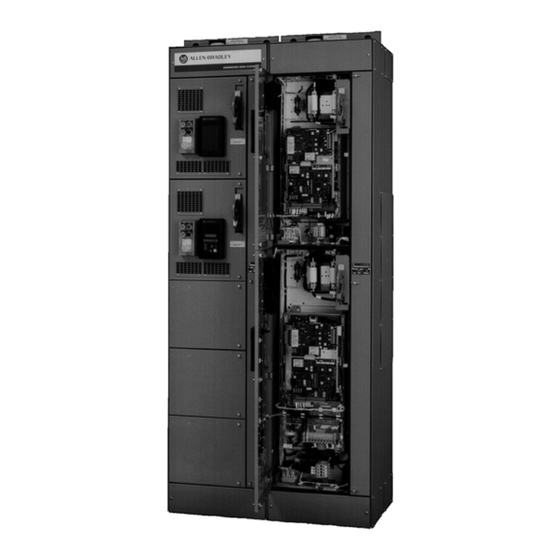
Allen-Bradley 1336 PLUS Selection Manual
Digital ac drives in centerline motor control centers
Hide thumbs
Also See for 1336 PLUS:
- Instructions manual (12 pages) ,
- Quick start manual (6 pages) ,
- Instruction manual (4 pages)
Table of Contents
Advertisement
Quick Links
Advertisement
Table of Contents

Related Manuals for Allen-Bradley 1336 PLUS


Summary of Contents for Allen-Bradley 1336 PLUS
- Page 1 Bulletin 2362 - Digital AC Drives in CENTERLINE® Motor Control Centers 1336 PLUS™ - Variable Frequency 1336 PLUS™ II 1336 FORCE - Vector Control 1336 IMPACT PowerFlex® 700 PowerFlex® 700S Bulletin 2362 Units Bulletin 2362HA 125HP Roll-Out Unit Selection Guide...
-
Page 3: Table Of Contents
Drive Unit Options ............1-3 Chapter 2 1336 PLUS™ Variable Frequency, 1336 PLUS™ II, 1336 FORCE - Vector Control, 1336 IM- PACT Product Selection Catalog Number Explanation . - Page 4 Table of Contents...
-
Page 5: Preface
Bulletin 2362 AC motor drive units are specifically designed for use in CENTERLINE® MCC lineups. You may select from numerous 1336 PLUS® Variable Frequency, 1336 PLUS® II Variable Frequency, 1336 FORCE Field-Oriented Control Vector, 1336 Impact, PowerFlex® 700, and PowerFlex® 700S digital AC motor drives. You may have these drives configured for either a common-AC or a common-DC power bus configuration. -
Page 6: Plug-In Drive Units
Introduction mounted within the drive units allow for the connection of remote operator devices, I/O signals, etc. Note: NEMA Type 1 is the standard feature; and NEMA Type 1 with unit door area gaskets and door fan filters is available as an option. A variety of available options provide increased unit functionality. -
Page 7: Roll-Out Drive Units
Introduction Roll-Out Drive Units The basic standard roll-out drive unit includes: • the selected drive, mounted and wired on a roll-out chassis assembly • a fused-disconnect switch with an operator mechanism and appropriate fuses • bus-to-disconnect wiring • output common-mode chokes in all D, E, and F-frame units and in G-frame 2362H units (common DC bus 1336 FORCE) •... - Page 8 Introduction Notes:...
-
Page 9: Chapter 1 Powerflex® 700 And 700S Product Selection
Chapter PowerFlex® 700 and 700S Product Selection Catalog Number Use the following tables for determining the catalog number used to order PowerFlex 700 and 700S drives in Bulletin 2362 MCCs. Explanation 2362 OPTIONS Frame Size Input Voltages Disconnect Type Table 1.A on A 230V AC Bus DA Fused Disconnect page 1-2... -
Page 10: Frame Selection
PowerFlex® 700 and 700S Product Selection Frame Selection The following table is used to determine the frame size required based on the desired Drive Type, Input Voltage and Horsepower. Table 1.A PowerFlex 700 ad 700S Frame Selection PowerFlex® 700 Frame Sizes Drive Type Duty... -
Page 11: Drive Unit Options
PowerFlex® 700 and 700S Product Selection Drive Unit Options Table 1.B PowerFlex® 700 and 700S Drives Options Available to All Units: Option Option Code Description Control Power Individual 115V AC-secondary, control power transformer (supplied per drive unit). Includes primary fusing (1)(6) Source 115V AC control power, factory wired from 115V AC control bus to drive unit (requires control bus) - Page 12 PowerFlex® 700 and 700S Product Selection Options Available to All Units: Option Option Code Description Drive Duty Cycle 99ND Normal Duty 99HD Heavy Duty (18)(19)(21) Emissions 14EMA CE filter and common mode choke (20)(21) 14EMB CE filter and no common mode choke (22) 14EMB1 CE filter and external common mode choke...
- Page 13 (3) You may select up to (1) option from this group. (4) Pilot lights are Allen-Bradley® Bulletin 800M products and the pushbutton is an Allen-Bradley Bulletin 800T device. (5) If one drive unit has base channels in any lineup, the entire lineup must have base channels. Base channels add 1.5 inches to the unit height.
- Page 14 PowerFlex® 700 and 700S Product Selection Notes:...
-
Page 15: Catalog Number Explanation
1336 FORCE - Vector Control, 1336 IMPACT Product Selection Catalog Number Use the following tables for determining the catalog number used to order 1336 PLUS™ Variable Frequency, 1336 PLUS™ II, 1336 FORCE - Vector Explanation Control, and 1336 IMPACT drives in Bulletin 2362 MCCs. 2362... -
Page 16: Frame Selection
1336 PLUS™ Variable Frequency, 1336 PLUS™ II, 1336 FORCE - Vector Control, 1336 IMPACT Product Selection Frame Selection The following table is used to determine the frame size required based on the desired Drive Type, Input Voltage and Horsepower. Table 2.A 1336 Frame Selection... -
Page 17: Drive Unit Options
1336 PLUS™ Variable Frequency, 1336 PLUS™ II, 1336 FORCE - Vector Control, 1336 IMPACT Product Selection Drive Unit Options Table 2.B Drive Unit Options Options Available to All Units: Option Option Code Description Control Power Individual 115V AC-secondary, control power transformer (supplied per drive unit). Includes primary fusing... - Page 18 1336 PLUS™ Variable Frequency, 1336 PLUS™ II, 1336 FORCE - Vector Control, 1336 IMPACT Product Selection Options Available to 2362F & 2362H Units: Option Option Code Description Control Logic 14L5 24V DC Interface 14L6 115V AC Boards Drive Adapter 14CN ControlNet (version 1.5) Adapter...
- Page 19 1336 PLUS™ Variable Frequency, 1336 PLUS™ II, 1336 FORCE - Vector Control, 1336 IMPACT Product Selection Enclosure Options Available to All Units: Option Description Section Input Voltage > 230V AC 380/460V AC 575V AC 310V DC 512V/620V DC 775V DC...
- Page 20 1336 PLUS™ Variable Frequency, 1336 PLUS™ II, 1336 FORCE - Vector Control, 1336 IMPACT Product Selection Notes:...
-
Page 21: Chapter 3 Motor Control Center Vertical Sections
Chapter Motor Control Center Vertical Sections Features and Modifications Table 3.A Motor Control Center Vertical Section Features and Modifications Section Features and Modifications App. Notes Description Section 1, 2, 3, 10 15” Deep Depth 20” Deep 25” Deep (flush back) Horizontal Tin-plated copper busbar Power Bus... - Page 22 Motor Control Center Vertical Sections Notes:...
-
Page 23: Understanding Busbar Splice Catalog Numbers
Chapter Busbar Splice Kits Understanding Busbar Each character of the catalog number identifies a specific type or size of a particular busbar splice kit. The first four numbers represent the family of Splice Catalog Numbers products (for example, 2300). The remaining characters represent a specific version. -
Page 24: Control Bus Splice Kit Catalog Numbers
Busbar Splice Kits Table 4.B DC Power Bus Splice Kits Compatible with Frame Sizes Continuous Power Bus 1336 PowerFlex Rating (Amps) Straight Splice Kit Offset Splice Kit A, B, C, D, E, F 0 - 9 2300H-SKD-L08 2300H-SKD-Z08 A, B, C, D, E, F 0 - 9 1600 2300H-SKD-L16 2300H-SKD-Z16... - Page 26 www.rockwellautomation.com Power, Control and Information Solutions Americas: Rockwell Automation, 1201 South Second Street, Milwaukee, WI 53204-2496 USA, Tel: (1) 414.382.2000, Fax: (1) 414.382.4444 Europe/Middle East/Africa: Rockwell Automation SA/NV, Vorstlaan/Boulevard du Souverain 36, 1170 Brussels, Belgium, Tel: (32) 2 663 0600, Fax: (32) 2 663 0640 Asia Pacific: Rockwell Automation, Level 14, Core F, Cyberport 3, 100 Cyberport Road, Hong Kong, Tel: (852) 2887 4788, Fax: (852) 2508 1846 Publication 2362-SG001A-EN-P –...
Need help?
Do you have a question about the 1336 PLUS and is the answer not in the manual?
Questions and answers