Allen-Bradley PowerFlex 700 Installation Instructions Manual
Frame 9 components replacement
Hide thumbs
Also See for PowerFlex 700:
- Quick start manual ,
- User manual (198 pages) ,
- Installation instructions manual (96 pages)

Related Manuals for Allen-Bradley PowerFlex 700


Summary of Contents for Allen-Bradley PowerFlex 700
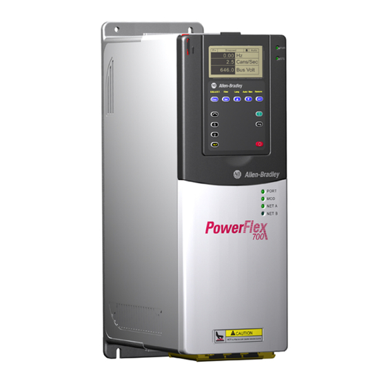
- Page 1 Installation Instructions PowerFlex 700 Drive - Frame 9 Components Replacement Catalog Numbers XXX XXX XXXX XXX XXX XXX...
- Page 2 Identifies information that is critical for successful application and understanding of the product. IMPORTANT Allen-Bradley, Rockwell Software, Rockwell Automation, and TechConnect are trademarks of Rockwell Automation, Inc. Trademarks not belonging to Rockwell Automation are property of their respective companies.
-
Page 3: Table Of Contents
Table of Contents Summary of Changes New and Updated Information........5 Preface Introduction. - Page 4 Table of Contents Notes: Rockwell Automation Publication 20B-IN025B-EN-P - January 2011...
-
Page 5: New And Updated Information
Summary of Changes This manual contains new and updated information. Changes throughout this revision are marked by change bars, as shown to the right of this paragraph. New and Updated This table contains the changes made to this revision. Information Topic Page Preface... - Page 6 Summary of Changes Notes: Rockwell Automation Publication 20B-IN025B-EN-P - January 2011...
-
Page 7: Introduction
Preface Introduction This publication provides guidelines for replacing the major components in the PowerFlex 700 Frame 9 drive. Component Kits All kits include necessary components, ESD wrist strap and hardware (if required), and thermal grease (if required). Description Kit Catalog No. -
Page 8: Recommended Tools
Preface Description Kit Catalog No. Notes Miscellaneous (continued) Capacitor Bus Finger Kit SK-G1-FLXBUS1 Included with the kit for Inverter Power Module (IGBT). Can be ordered separately. Includes: • Three positive Flexible Capacitor Busbars • Three negative Flexible Capacitor Busbars MOV Surge Suppressor SK-G1-MOV1-F89 For AC input drives only. -
Page 9: Safety Precautions
The precautions and general installation requirements provided in the PowerFlex 700 Frame 7-10 Installation Instructions (publication 20B-IN014) and the PowerFlex 700 User Manual (publication 20B-UM002) must be followed with those included here. ATTENTION: To avoid an electric shock hazard, ensure that all power has been removed before proceeding. -
Page 10: Important Initial Steps
Component damage may result if you ignore electrostatic discharge control procedures. If you are not familiar with static control procedures, refer to Guarding Against Electrostatic Damage, Allen-Bradley publication 8000-4.5.2, or any other applicable ESD protection handbook. -
Page 11: Component Diagrams And Torque Specs
Chapter Component Diagrams and Torque Specs Overview Drive components and their locations are identified in this chapter, as well as torque specifications for fasteners that are part of component removal and replacement. Rockwell Automation Publication 20B-IN025B-EN-P - January 2011... - Page 12 Chapter 1 Component Diagrams and Torque Specs Figure 1 - Frame 9 - AC Drive Components Drive Shown With Stacking Panel Removed Gate Interface Board (3) Current Transducer (3) Transitional Busbar Flexible Capacitor Busbars (18) Output Busbar (3) DC Bus Capacitor (18) IGBT Interface Board and IGBT (3 each) Tie Down Capacitor Mount (3)
- Page 13 Component Diagrams and Torque Specs Chapter 1 Figure 2 - Frame 9 - DC Drive Components Drive Shown With Stacking Panel Removed Gate Interface Board (3) Current Transducer (3) Transitional Busbar Flexible Capacitor Busbars (18) Output Busbar (3) IGBT Interface Board and IGBT DC Bus Capacitor (18) (3 each) Snubber Capacitors (9) for IGBTs...
- Page 14 Chapter 1 Component Diagrams and Torque Specs Figure 3 - Frame 9 Busbars (AC Drive shown) DC- Bar DC+ Bar Transitional Bus Bar Assembly Rockwell Automation Publication 20B-IN025B-EN-P - January 2011...
- Page 15 Component Diagrams and Torque Specs Chapter 1 Figure 4 - Frame 9 (AC input drive shown) DC Link Choke Output Inverter Snubber Gate Interface Board Connection (Top) Capacitors (3 per IGBT) Current Transducer (3) Transitional Busbar DC Capacitor Bank (Under Transitional Busbar) Inverter Power Module IGBT (under Capacitors) Motor Busbars (U, V, W)
-
Page 16: Circuit Boards
Chapter 1 Component Diagrams and Torque Specs Circuit Boards Figure 5 - Circuit Boards on Frame 9 Encoder Board (optional) Blower Control Panel Description · TB11 Fuse · HIM Cradle/Communication Board Holders · Communication Board Slots Safety Shield (for optional devices) Overload Protector ·... -
Page 17: Fastener Torque Specifications
Component Diagrams and Torque Specs Chapter 1 Fastener Torque Torque Sequence Specifications ATTENTION: When mounting components to a drive’s heat sink, component fastener torque sequences and tolerances are crucial to component-to-heat sink heat dissipation. Components can be damaged if initial tightening procedure is not performed to specification. - Page 18 Chapter 1 Component Diagrams and Torque Specs Torque Specifications The following table lists fastener locations by component, how the fasteners are used, and torque specifications. See Torque Sequence in this chapter for fastening two-point, four-point, and six-point components to the heat sink. Torque Component Fastener Application...
- Page 19 Component Diagrams and Torque Specs Chapter 1 Torque Component Fastener Application lb•in N•m Wires Wires to TB3 8 – 10 0.9 – 1.1 CT Mounting Plate Mounting Plate to CT Clamping Plate CT Clamping Plate Clamping Plate to Busbar Power Cables Cables to terminals Main Control, Gate Driver, Plates to chassis...
- Page 20 Chapter 1 Component Diagrams and Torque Specs Notes: Rockwell Automation Publication 20B-IN025B-EN-P - January 2011...
-
Page 21: Basic Component Removal Procedures
Chapter Basic Component Removal Procedures Overview Component removal procedures detailed in this chapter are located on the Stacking Panel and Transitional Busbar assemblies highlighted below. Circuit Boards on page 16 to identify the various panels that comprise the Stacking Panel assembly. Transitional Busbar Assembly Stacking Panel Assembly Rockwell Automation Publication 20B-IN025B-EN-P - January 2011... -
Page 22: Main Control Panel
Chapter 2 Basic Component Removal Procedures Main Control Panel Chapter 1 - Drive Components to locate the component detailed in these instructions. Remove Components 1. Read and follow the Safety Precautions on page 8 Important Initial Steps on page 2. Remove safety shields as needed. Ribbon Cable from Main Control Board to Power Interface Board Mounting Screws (2) that adjoin... - Page 23 Basic Component Removal Procedures Chapter 2 9. Disconnect wire harnesses from TB11 to: • J4 on the Switch Mode Power Supply Board • TB1 and TB2 on the Power Interface Board 10. Label and remove all customer wiring from TB11. 11.
-
Page 24: Blower Control Panel
Chapter 2 Basic Component Removal Procedures Blower Control Panel Chapter 1 - Drive Components to locate the component detailed in these instructions. Remove Components 1. Read and follow the Safety Precautions on page 8 Important Initial Steps on page 2. Disconnect the three wires (red, white, and blue) at the top of the blower fuse block. -
Page 25: Stacking Panel
Basic Component Removal Procedures Chapter 2 Stacking Panel Chapter 1 - Drive Components to locate the component detailed in these instructions. Remove Components 1. Read and follow the Safety Precautions on page 8 Important Initial Steps on page 2. All wiring and terminals attached to the Stacking Panel are shown below. Label any unidentified wiring and terminals before disconnecting. - Page 26 Chapter 2 Basic Component Removal Procedures Connected Component Label on Wire Label on Board Notes or Connector Power Interface Board U Phase CT V Phase CT W Phase CT UP, VP, WP U, V, W positive gates UN, VN, WN U, V, W negative gates 3.
- Page 27 Basic Component Removal Procedures Chapter 2 9. Remove the six nuts for mounting the Stacking Panel. Shown with Main Control Panel and Blower Control Panel Removed Mounting Nuts (6) 10. Remove Stacking Panel; carefully set aside. Install Components 1. When instructed for the component you are replacing, reinstall the Stacking Panel components in the reverse order of removal.
-
Page 28: Transitional Busbar
Chapter 2 Basic Component Removal Procedures Transitional Busbar Chapter 1 - Drive Components to locate the component detailed in these instructions. Remove Components 1. Read and follow the Safety Precautions on page 8 Important Initial Steps on page 2. Remove Main Control Panel on page 3. - Page 29 Basic Component Removal Procedures Chapter 2 9. Remove all IGBT Snubber components: a. Remove the six nuts that secure each set of Snubber Capacitors. Remove the capacitors, and save nuts and capacitors. Tie Down Capacitor Mount Screw Snubber Snubber Capacitor Capacitors Mount Nuts (6) Tie Down...
- Page 30 Chapter 2 Basic Component Removal Procedures 10. Cut tie wraps for the Balancing Resistor wiring. 11. Disconnect the yellow wire for the Balancing Resistor. You do not need to disconnect the blue and black wires. Balancing Resistor Resistor wiring tie wraps Balancing Resistor yellow wire Disconnect here 12.
- Page 31 Basic Component Removal Procedures Chapter 2 14. Remove the Transitional Busbar unit. Transitional Busbar Unit Removed Negative (DC-) Flexible Capacitor Busbar (attached to top side of Transitional Busbar) Positive (DC+) Flexible Capacitor Busbar (attached to bottom side of Transitional Busbar) Rockwell Automation Publication 20B-IN025B-EN-P - January 2011...
- Page 32 Chapter 2 Basic Component Removal Procedures Install Components See the photographs in the preceding Transitional Busbar section to identify any components discussed in this section. Positive (DC+) Flexible Capacitor Busbar (short) Negative (DC-) Flexible Capacitor Busbar (tall) Each IGBT replacement kit includes three positive (DC+) and three IMPORTANT negative (DC-) Flexible Capacitor Busbars.
- Page 33 Basic Component Removal Procedures Chapter 2 6. Reinstall the screws for the four side standoffs and brackets to secure the Transitional Busbar assembly to the chassis. a. Torque the screws to 5.6 N•m (50 lb•in) to secure the brackets to the four red glastic spacers.
- Page 34 Chapter 2 Basic Component Removal Procedures Notes: Rockwell Automation Publication 20B-IN025B-EN-P - January 2011...
-
Page 35: Component Replacement Procedures
Chapter Component Replacement Procedures Overview Component procedures detailed in this chapter apply to PowerFlex 700 Frame 9 drives for AC or DC input. Removal and replacement instructions for the Stacking Panel and Transitional Bar assemblies are detailed in Chapter 2. - Page 36 Chapter 3 Component Replacement Procedures 6. Holding the Communications Panel, release the cable from the DPI Port 2 clamp and set the Communications Panel aside. Ribbon Cable from Main Control Panel to Power Interface Board Main Control Board Screws (6) Connector Screw Main Control Board...
- Page 37 Component Replacement Procedures Chapter 3 Install Components 1. Install the new Main Control Board with six screws and two hex standoffs (if Encoder Board is present). 2. If present, reinstall the Encoder Board with two screws, taking care to match the J7 connectors. 3.
-
Page 38: T-Comm Board
Chapter 3 Component Replacement Procedures T-Comm Board Chapter 1 - Drive Components to locate the component detailed in these instructions. Remove Components 1. Read and follow the Safety Precautions on page 8 Important Initial Steps on page 2. Remove the Main Control Board: a. - Page 39 Component Replacement Procedures Chapter 3 b. Remove and save the four mounting screws. 4. If the 20-Comm-C Board is not used, remove the screw securing the T- Comm grounding tab. T-Comm grounding tab screw T-Comm grounding tab flat T-Comm grounding tab upright 5.
-
Page 40: Power Interface Board
Chapter 3 Component Replacement Procedures Install Components 1. Install the new T-Comm Board. 2. Verify the board is locked into all seven locking tabs. 3. Carefully bend the T-Comm grounding tab until it is flush with the screw mount on the Main Control Board. 4. - Page 41 Component Replacement Procedures Chapter 3 3. Remove wiring to this Board, and wiring from this board to the Switch Mode Power Supply Board. DC input shown Spacers (9) Connector Wire Color(s) Connects To: Ribbon J2 on Main Control Board (ribbon cable) Black J1 on Switch Mode Power Supply Board Black...
- Page 42 Chapter 3 Component Replacement Procedures 4. Remove the two mounting torx screws located at the upper right and lower left corners of the board as shown at right. 5. Using your fingers or needle-nose pliers, squeeze the tabs of each of the nine spacers (see previous page for their locations), and separate the Power Interface Board from the mounting plate.
-
Page 43: Switch Mode Power Supply Board
Component Replacement Procedures Chapter 3 Switch Mode Power Chapter 1 - Drive Components to locate the component detailed in these instructions. Supply Board Remove Components 1. Read and follow the Safety Precautions on page 8 Important Initial Steps on page 2. - Page 44 Chapter 3 Component Replacement Procedures 5. Using your fingers or needle-nose pliers, squeeze the tabs of each of the three spacers and separate the Switch Mode Power Supply Board from the mounting plate. 6. Remove the Switch Mode Power Supply Board; return or dispose of it properly.
-
Page 45: Power Supply Board (For Current Transducers)
Component Replacement Procedures Chapter 3 24V Power Supply Board Chapter 1 - Drive Components to locate the component detailed in these instructions. (for Current Transducers) Remove Components 1. Read and follow the Safety Precautions on page 8 Important Initial Steps on page 2. -
Page 46: Precharge Board
Chapter 3 Component Replacement Procedures Precharge Board Chapter 1 - Drive Components to locate the component detailed in these instructions. Remove Components 1. Read and follow the Safety Precautions on page 8 Important Initial Steps on page 2. Perform Remove Blower Control Panel on page 3. - Page 47 Component Replacement Procedures Chapter 3 AC Input DC Input Screw Spacers (3) Lock Screws (6) 5. For AC input: Remove the Precharge Board mounting torx screw located at the upper left corner of the Precharge Board. 6. Remove the Precharge Board; return or dispose of it properly. •...
-
Page 48: Dc Bus Filter Board
Chapter 3 Component Replacement Procedures DC Bus Filter Board Chapter 1 - Drive Components to locate the component detailed in these instructions. Remove Components 1. Read and follow the Safety Precautions on page 8 Important Initial Steps on page 2. Remove the safety shield over the DC Bus Filter Board. 3. -
Page 49: Bus Capacitor
Component Replacement Procedures Chapter 3 Bus Capacitor Chapter 1 - Drive Components to locate the component detailed in these instructions. Remove Components 1. Read and follow the Safety Precautions on page 8 Important Initial Steps on page 2. Perform Remove Main Control Panel on page 3. - Page 50 Chapter 3 Component Replacement Procedures Install Components ATTENTION: Install each capacitor so its vent plug is at the top or 12 o’clock. Component and system damage may result if you position any Bus Capacitor incorrectly. 1. Replace setscrews for each new Capacitor using a 3 mm angle hex wrench. Each Capacitor needs a short and long setscrew;...
-
Page 51: Capacitor Bank Fan
Component Replacement Procedures Chapter 3 Capacitor Bank Fan Chapter 1 - Drive Components to locate the component detailed in these instructions. Remove Components 1. Read and follow the Safety Precautions on page 8 Important Initial Steps on page 2. Perform Remove Main Control Panel on page 3. -
Page 52: Balancing Resistor
Chapter 3 Component Replacement Procedures Balancing Resistor Chapter 1 - Drive Components to locate the component detailed in these instructions. Remove Components 1. Read and follow the Safety Precautions on page 8 Important Initial Steps on page 2. Perform Remove Main Control Panel on page 3. -
Page 53: Inverter Power Module (Igbt)
Component Replacement Procedures Chapter 3 Inverter Power Module Kit includes: (IGBT) Component IGBT module with circuit board Gate Interface Board Gate Interconnect Harness Flexible Capacitor Busbar, Positive Flexible Capacitor Busbar, Negative Tie Down Capacitor Mount Snubber Capacitor The photograph below is an example of an IGBT module failure. IGBT damage may impact other components near or associated with IGBT operation, including components that are not part of the aforementioned kit. - Page 54 Chapter 3 Component Replacement Procedures Remove Components 1. Read and follow the Safety Precautions on page 8 Important Initial Steps on page 2. Locate the Inverter Power Module to be replaced. Tie Down Capacitor Mount AC Output Busbar Snubber Current IGBT Gate Interface Capacitors...
- Page 55 Component Replacement Procedures Chapter 3 AC Output Busbar Torx AC Output Busbar Output Busbar Screws (6) Standoff Nuts (2) Hex Head Bolts(2) Output Busbar Output Busbar Standoff Nut Torx Head Bolt and Setscrew 5. Perform Remove all IGBT Snubber components: on page 6.
- Page 56 Chapter 3 Component Replacement Procedures Install Components 1. Carefully examine the Transitional Busbar and Bus Capacitors for damage. When replacing any IGBT, it is recommended that you replace all Bus Capacitors. If needed, see Bus Capacitor on page 49 to replace damaged Bus Capacitors.
- Page 57 Component Replacement Procedures Chapter 3 Shown with Transitional Busbar and all Flexible Capacitor Busbars installed 4. Reinstall the Transitional Busbar as instructed on page 32. 5. Install the three supplied negative (DC-) Flexible Capacitor Busbars in positions 1, 3, and 5 on the IGBT. The negative (DC-) Flexible Capacitor Busbars have a higher angle.
-
Page 58: Gate Interface Board
Chapter 3 Component Replacement Procedures 8. Install the Gate Interface Board: a. Install the Gate Interface Board using the four nuts removed previously. Torque screws to 2.9 N•m (26 lb•in). b. Install the supplied Gate Interconnect Harness. c. Connect wiring between the IGBT and Gate Interface Board as shown Gate Interface Board on page d. - Page 59 Component Replacement Procedures Chapter 3 5. Remove the four 7 mm board-mounting nuts. 6. Remove the board; return or dispose of it properly. Gate Interface Board Mounting Nuts (4) Install Components 1. Install the new board. 2. Torque mounting nuts to 1.6 N•m (14 lb•in). 3.
-
Page 60: Current Transducer
Chapter 3 Component Replacement Procedures Current Transducer Chapter 1 - Drive Components to locate the component detailed in these instructions. Remove Components 1. Read and follow the Safety Precautions on page 8 Important Initial Steps on page 2. Locate the Current Transducer to be replaced. 3. - Page 61 Component Replacement Procedures Chapter 3 Install Components 1. Mount brackets to the new Current Transducer. Torque screw to 2.9 N•m (26 lb•in). 2. Slide Output Busbar through the Current Transducer assembly with the angled end to the left. 3. Replace the Current Transducer assembly in mounting position by reversing the process used in Step 5.
-
Page 62: Converter Power Module (Scr) - Ac Input Only
Chapter 3 Component Replacement Procedures Converter Power Module If any Converter SCR module fails, all three SCR modules should be IMPORTANT (SCR) - AC Input Only replaced (kit includes all three modules). Chapter 1 - Drive Components to locate the component detailed in these instructions. - Page 63 Component Replacement Procedures Chapter 3 Install Components 1. Using isopropyl alcohol, thoroughly clean the Heatsink mounting surface where each new SCR module will be installed. 2. Verify that the mounting surface of each new SCR module is clean. If not, clean with isopropyl alcohol.
-
Page 64: Converter Snubber Resistors - Ac Input Only
Chapter 3 Component Replacement Procedures Converter Snubber Chapter 1 - Drive Components to locate the component detailed in these instructions. Resistors - AC Input Only Remove Components Kit includes Snubber Board and Resistor. 1. Read and follow the Safety Precautions on page 8 Important Initial Steps on page 2. - Page 65 Component Replacement Procedures Chapter 3 Install Components 1. Using isopropyl alcohol, clean the surface where the new Snubber Resistor will be installed. 2. Verify that the mounting surface of the new Snubber Resistor is clean. If not, clean with isopropyl alcohol. 3.
-
Page 66: Converter Snubber Board - Ac Input Only
Chapter 3 Component Replacement Procedures Converter Snubber Board - Chapter 1 - Drive Components to locate the component detailed in these instructions. AC Input Only Remove Components 1. Read and follow the Safety Precautions on page 8 Important Initial Steps on page 2. -
Page 67: Fan Transformer
Component Replacement Procedures Chapter 3 Fan Transformer Chapter 1 - Drive Components to locate the component detailed in these instructions. Remove Components 1. Read and follow the Safety Precautions on page 8 Important Initial Steps on page Fan Transformer Label and unplug these two red wires Label and disconnect these three wires... -
Page 68: Heatsink Fan - Removal From Back Of Drive
Chapter 3 Component Replacement Procedures Heatsink Fan - Removal The Heatsink Fan is located on the back of the drive. from Back of Drive (For equipment clearance considerations, the Fan can also be removed from the front of the drive. See Heatsink Fan - Removal from Front of Drive on page 70.) - Page 69 Component Replacement Procedures Chapter 3 Fan Cover Screw Locations on Back of Drive 4 on top and bottom for a total of 8 3 on right side NOTE: No screws on left side Install Components 1. Place Fan assembly into the chassis but not installed in final position. Leave space for accessing Fan cables from the front of the drive.
-
Page 70: Heatsink Fan - Removal From Front Of Drive
Chapter 3 Component Replacement Procedures Heatsink Fan - Removal The Heatsink Fan is located on the back of the drive. These instructions explain how to remove the fan from the front of the drive. from Front of Drive Heatsink Fan (DC input drive shown) Chapter 1 - Drive Components to locate the component detailed in these... - Page 71 Component Replacement Procedures Chapter 3 Do not disconnect the U, V, or W Busbars at the bottom. AC Drive Shown 17 mm bolt on 17 mm bolt on DC+ Busbar DC– Busbar Do not 16 mm bolts disconnect Busbars at the bottom.
- Page 72 Chapter 3 Component Replacement Procedures Do not disconnect the U, V, or W Busbars at the bottom. 11 mm Nut 17 mm and Setscrew Bolts (2) Current Transducer U, V, and W Busbars Output Busbar 8. Remove the four 10 mm nuts for the busbars mounting plate. AC Input Drive Shown Busbar Mounting Plate 10 mm nuts (4)
- Page 73 Component Replacement Procedures Chapter 3 9. Remove the entire busbar and mounting plate assembly. Set aside. AC Input Drive DC Input Drive 10. Unplug the fan cables. 11. For AC input only: Remove the MOV Surge Suppressor as instructed on page 79.
- Page 74 Chapter 3 Component Replacement Procedures 13. Remove the 12 exterior screws on the fan mounting plate. Fan Mounting Plate Screws (12) Busbar Mounting Plate Bracket 14. Carefully remove the mounting plate and fan through the front of the drive chassis; you may need to pry the mounting plate away from the gasket.
-
Page 75: Thermal Sensors
Component Replacement Procedures Chapter 3 Thermal Sensors In the AC input drive, the Thermal Sensor system consists of: • A connector to J8 on each of the three Gate Interface Boards. • A sensor secured to the Heatsink above the SCR modules. •... - Page 76 Chapter 3 Component Replacement Procedures Thermal Sensor wiring for AC input drive Thermal Sensor wiring for DC input drive Heatsink Heatsink Thermal Thermal Sensor Sensor CNV BOT CNV TOP CNV-3 Main Control Main Control Panel Thermal Sensor Panel Thermal Sensor Power Power Interface...
- Page 77 Component Replacement Procedures Chapter 3 Remove Components 1. Read and follow the Safety Precautions on page 8 Important Initial Steps on page 2. Cut the wire ties for the Heatsink wiring harness along the Gate Thermal Interface Boards. Sensor & Screw 3.
-
Page 78: Dc Link Choke - Ac Input Only
Chapter 3 Component Replacement Procedures DC Link Choke - Chapter 1 - Drive Components to locate the component detailed in these instructions. AC Input Only Remove Components 1. Read and follow the Safety Precautions on page 8 Important Initial Steps on page 2. -
Page 79: Mov Surge Suppressor - Ac Input Only
Component Replacement Procedures Chapter 3 MOV Surge Suppressor - Chapter 1 - Drive Components to locate the component detailed in these instructions. AC Input Only Remove Components 1. Read and follow the Safety Precautions on page 8 Important Initial Steps on page 2. -
Page 80: Precharge Scr Module And Diode - Dc Input Only
Chapter 3 Component Replacement Procedures Precharge SCR Module and Chapter 1 - Drive Components to locate the component detailed in these instructions. Diode - DC Input Only Remove Components 1. Read and follow the Safety Precautions on page 8 Important Initial Steps on page 2. - Page 81 Component Replacement Procedures Chapter 3 3. Using a 3- or 4-inch paint roller or putty knife, apply a thin, even coating of the supplied thermal grease to the mounting surface of each SCR module and Diode. WARNING: In the next step, be sure to properly install the modules as shown.
- Page 82 Chapter 3 Component Replacement Procedures Notes: Rockwell Automation Publication 20B-IN025B-EN-P - January 2011...
- Page 84 Rockwell Automation Support Rockwell Automation provides technical information on the Web to assist you in using its products. At http://www.rockwellautomation.com/support/, you can find technical manuals, a knowledge base of FAQs, technical and application notes, sample code and links to software service packs, and a MySupport feature that you can customize to make the best use of these tools.
Need help?
Do you have a question about the PowerFlex 700 and is the answer not in the manual?
Questions and answers