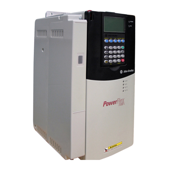
Allen-Bradley PowerFlex 700S Original Instructions Manual
Drives with phase ii control
Hide thumbs
Also See for PowerFlex 700S:
- Quick start manual (52 pages) ,
- User manual (22 pages) ,
- Manual (16 pages)
Table of Contents
Advertisement
Quick Links
Technical Data
PowerFlex 700S Drives with Phase II Control
Original Instructions
Bulletin Number 20D
Topic
Product Overview
Catalog Number Explanation
Product Selection
Factory Installed Options
User Installed Options
Installation Considerations
Power Terminal Block Specifications
Control Terminal Block Specifications
Drive Ratings
Drive Mounting Clearances and Dimensions
Specifications
Derating Guidelines
Carrier Derating Curves
Watts Loss Curves - Frames 10...14
Page
Below
10
12
16
18
30
38
48
49
79
103
107
108
115
Advertisement
Table of Contents

Related Manuals for Allen-Bradley PowerFlex 700S


Summary of Contents for Allen-Bradley PowerFlex 700S
- Page 1 Technical Data PowerFlex 700S Drives with Phase II Control Original Instructions Bulletin Number 20D Topic Page Below Product Overview Catalog Number Explanation Product Selection Factory Installed Options User Installed Options Installation Considerations Power Terminal Block Specifications Control Terminal Block Specifications...
- Page 2 This manual provides information that is needed to start up, program, and troubleshoot PowerFlex 700S Phase II Drives. PowerFlex 700S Phase II, Frame 1…6, AC Drives Installation Instructions, This document provides information that is needed to install and wire a frame 1…6 PowerFlex 700S Phase II drive. publication 20D-IN024 PowerFlex 700S and PowerFlex 700H Frames 9…14 Drives Installation...
- Page 3 PowerFlex 700S Drives with Phase II Control Product Overview ® The PowerFlex 700S AC drive with Phase II control offers high-performance drive control, advanced programming features, and built-in diagnostics for handling the most demanding applications. The PowerFlex 700S with DriveLogix™ combines the powerful...
- Page 4 • DriveLogix™ offers embedded Logix control for application programmability and control of auxiliary functions in one package, the PowerFlex 700S drive with DriveLogix. The following features are included with DriveLogix: • Common programming environment and multiple programming languages supported by all Logix platforms.
- Page 5 PowerFlex 700S Drives with Phase II Control Start Up, Programming • The PowerFlex 700S has optimized global voltage settings for quick configuration anywhere in the world. Multiple reset defaults make setup for your voltage/frequency fast and easy. • An optional LCD Human Interface Module (HIM) provides programming, start up information, diagnostics, and other information in full, easy to understand text.
- Page 6 PowerFlex 700S Drives with Phase II Control Operation • Multiple high-performance motor control algorithms: Flux Vector Control utilizes patented FORCE™ Technology for sensor and sensorless induction motor control and Brushless Permanent Magnet motor operation, provide maximum application flexibility. • An array of feedback options, including a standard incremental encoder, an optional incremental encoder, resolver, and high-resolution encoder feedback interface cards optimize the accuracy of speed and position regulators.
- Page 7 For more information, contact Allen-Bradley Drives Technical Support, M-F, 7:00 a.m. to 6:00 p.m. Central STD time: 262-512-8176 or refer to: http://www.ab.com/support/abdrives/...
- Page 8 PowerFlex 700S Drives with Phase II Control Performance Digital Current Regulator outperforms older style analog regulators in speed, repeatability, and drift. Current Limit Derivative U Phase Motor Current Current Gain Block Magnitude V Phase Motor Current Calculator W Phase Motor Current...
- Page 9 PowerFlex 700S Drives with Phase II Control High-Speed Analog and Digital I/O execute in 0.5 ms or less to provide fast response and fast capture for registration information and position data. Output relays, optically isolated and differentially isolated I/O are supplied.
- Page 10 PowerFlex 700S Drives with Phase II Control Catalog Number Explanation 1…3 5…7 2P1 A Drive HIM (Human Interface Machine) Comm Slot Code Type Code Version Code Operator Interface PowerFlex 700S None Blank Cover DPI ControlNet (Coax) Full Numeric LCD DPI DeviceNet...
- Page 11 PowerFlex 700S Drives with Phase II Control PowerFlex 700S ND Rating PowerFlex 700S ND Rating PowerFlex 700S ND Rating 208/240V, 60 Hz Input 480V, 60 Hz Input 600V, 60 Hz Input Code Amps Frame Code Amps Frame Code Amps Frame 17.5...
- Page 12 PowerFlex 700S Drives with Phase II Control Product Selection Frames 1…6 - IP20, NEMA/UL Type 1, (Position d = A) 208/240V AC, Six-pulse, Three-phase Drives 240V AC Input 208V AC Input IP20, NEMA/UL Type 1 Frame Size Output Amp Normal...
- Page 13 PowerFlex 700S Drives with Phase II Control 600…690V AC, Six-pulse, Three-phase Drives (1)(2) IP20, NEMA/UL Type 1 Frame 600V AC Input 690V AC Input Size Output Amp Normal Heavy- Output Amp Normal Heavy- Duty HP Duty HP Duty kW Duty kW Cont.
- Page 14 PowerFlex 700S Drives with Phase II Control 600…690V AC, Six-pulse, Three-phase Drives (1)(2) IP21, NEMA/UL Type 1 Frame 600V AC Input 690V AC Input Size Output Amp Normal Heavy- Output Amp Normal Heavy- Duty HP Duty HP Duty kW Duty kW Cont.
- Page 15 PowerFlex 700S Drives with Phase II Control 600…690V AC, Six-pulse, Three-phase Drives 600…690V AC Input IP20, NEMA/UL Type 1 Frame Size Output Amp Normal Heavy-Duty Duty HP Cont. 1 Min. 3 Sec. Cat. No., 20D… 261 (208) 287 (312) 375 (375)
- Page 16 PowerFlex 700S Drives with Phase II Control 810V DC Input Drives 810 DC Input 932 DC Input IP20, NEMA/UL Type 1 Frame Precharge Size Output Amp Normal Heavy- Output Amp Normal Heavy- Duty HP Duty HP Duty kW Duty kW Cont.
- Page 17 PowerFlex 700S Drives with Phase II Control Internal Dynamic Brake Resistors These resistors have a limited duty cycle. See the PowerFlex Dynamic Braking Resistor Calculator guide, publication PFLEX-AT001, to determine if an internal resistor will be sufficient for your application. An external resistor may be required.
- Page 18 PowerFlex 700S Drives with Phase II Control User Installed Options Human Interface Modules Remote (Panel Mount) LCD LCD Display, Full Numeric Remote (Panel Mount) LCD LCD Display, LCD Display, Full No HIM (Blank Plate) Display, Programmer Only Keypad, Handheld/Local,...
- Page 19 PowerFlex 700S Drives with Phase II Control Communication Option Kits Description Cat. No. ControlNet™ Communication Adapter (Coax) 20-COMM-C DeviceNet™ Communication Adapter 20-COMM-D EtherNet/IP™ Communication Adapter 20-COMM-E HVAC Communication Adapter 20-COMM-H CANopen® Communication Adapter 20-COMM-K Modbus/TCP Communication Adapter 20-COMM-M PROFIBUS™ DP Communication Adapter 20-COMM-P ControlNet™...
- Page 20 PowerFlex 700S Drives with Phase II Control Accessories Note: Please refer to publication number 1756-TD008 for details on SynchLink. Description Cat. No. SynchLink Board 20D-P2-SLB0 SynchLink Fiber Base Block 1751-SLBA SynchLink 4-Port Fiber Splitter Block 1751-SL4SP SynchLink Fiber Bypass Switch Block...
- Page 21 PowerFlex 700S Phase II Control with Expanded Cassette 20D-P2-CKE2 PowerFlex 700S Phase II Control with Slim Cassette 20D-P2-CKS2 PowerFlex 700S DriveLogix5730 Phase II Control with Expanded Cassette 20D-DL2-CKE2 PowerFlex 700S DriveLogix5730 Phase II Control with Slim Cassette 20D-DL2-CKS2 Rockwell Automation Publication 20D-TD002L-EN-P - July 2018...
- Page 22 PowerFlex 700S Drives with Phase II Control Internal Dynamic Brake Resistor Kits These resistors have a limited duty cycle. See the PowerFlex Dynamic Braking Resistor Calculator guide, publication PFLEX-AT001, to determine if an internal resistor will be sufficient for your application. An external resistor may be required.
- Page 23 PowerFlex 700S Drives with Phase II Control Isolation Transformers For installations that have specific types of AC supply configurations or require drive protection due to AC line disturbances, isolation transformers are available. Drive Motor Rating kW (HP) 240V, 60 Hz, Three-phase,...
- Page 24 PowerFlex 700S Drives with Phase II Control 240V, 60 Hz, Three-phase, 3% Impedance (continued) Drive Cat. Duty Input Line Reactor Output Line Reactor IP00 (Open Style) IP11 (NEMA Type 1) IP00 (Open Style) IP11 (NEMA Type 1) Cat. No. Cat. No.
- Page 25 PowerFlex 700S Drives with Phase II Control 240V, 60 Hz, Three-phase, 5% Impedance Drive Cat. Duty Input Line Reactor Output Line Reactor IP00 (Open Style) IP11 (NEMA Type 1) IP00 (Open Style) IP11 (NEMA Type 1) Cat. No. Cat. No.
- Page 26 PowerFlex 700S Drives with Phase II Control 480V, 60 Hz, Three-phase, 3% Impedance Drive Cat. Duty Input Line Reactor Output Line Reactor IP00 (Open Style) IP11 (NEMA Type 1) IP00 (Open Style) IP11 (NEMA Type 1) Cat. No. Cat. No.
- Page 27 PowerFlex 700S Drives with Phase II Control 480V, 60 Hz, Three-phase, 5% Impedance Drive Cat. Duty Input Line Reactor Output Line Reactor IP00 (Open Style) IP11 (NEMA Type 1) IP00 (Open Style) IP11 (NEMA Type 1) Cat. No. Cat. No.
- Page 28 PowerFlex 700S Drives with Phase II Control 600V, 60 Hz, Three-phase, 3% Impedance Drive Cat. Duty Input Line Reactor Output Line Reactor IP00 (Open Style) IP11 (NEMA Type 1) IP00 (Open Style) IP11 (NEMA Type 1) Cat. No. Cat. No.
- Page 29 PowerFlex 700S Drives with Phase II Control 600V, 60 Hz, Three-phase, 5% Impedance Drive Cat. Duty Input Line Reactor Output Line Reactor IP00 (Open Style) IP11 (NEMA Type 1) IP00 (Open Style) IP11 (NEMA Type 1) Cat. No. Cat. No.
- Page 30 Peak Voltage Protection for Motors with Lower Insulation Systems While the PowerFlex 700S Phase II drive contains the very best in reflected wave reduction techniques, some motors may have insulation systems with values well below the NEMA/UL standards. While these motors may perform to expectations, they must be protected from the reflected wave transients that all PWM drives produce.
- Page 31 PowerFlex 700S Drives with Phase II Control Single-phase Input Power PowerFlex 700S drives are typically used with a six-pulse, three-phase input supply. However, single-phase operation is possible under certain conditions as explained below: Frames Condition 1…6 Not currently rated under the UL508C listing. Rockwell Automation has verified that single-phase operation with output current that is derated by 50% of the six-pulse, three-phase ratings that are listed in the tables beginning on page will meet all safety requirements.
- Page 32 PowerFlex 700S Drives with Phase II Control Cooling Fan Voltage for Common Bus Drives Common Bus drives require user supplied 120V or 240V AC to power the cooling fans. The power source is connected between “0V AC” and the terminal corresponding to your source voltage (see Power Terminal Block Details, Frames 5 &...
- Page 33 IMPORTANT In the following tables, A “ ● ” in any of the latter columns will indicate that this drive rating can be used with an Allen-Bradley Terminator (1204-TFA1/1204-TFB2) and/or Reflected Wave Reduction Device with Common Mode Choke (1204-RWC-17) or without choke (1204-RWR2).
- Page 34 PowerFlex 700S Drives with Phase II Control 400V Shielded/Unshielded Cable - Meters (Feet) Drive No Solution Reactor Only Reactor + Damping Resistor or Reactor/RWR Resistor Available Options 1321-RWR Frame kHz 1000V 1200V 1488V 1600V 1000V 1200V 1488V 1600V 1000V 1200V 1488V 1600V Cat. No.
- Page 35 PowerFlex 700S Drives with Phase II Control (3) Resistor specification is based on two cables per phase. (4) Resistor specification is based on three cables per phase. (5) Resistor specification is based on four cables per phase. 480V Shielded/Unshielded Cable - Meters (Feet)
- Page 36 PowerFlex 700S Drives with Phase II Control 480V Shielded/Unshielded Cable - Meters (Feet) (continued) Drive No Solution Reactor Only Reactor + Damping Resistor or Reactor/RWR Resistor Available Options 1321-RWR Frame kHz 1000V 1200V 1488V 1600V 1000V 1200V 1488V 1600V 1000V 1200V 1488V 1600V Cat. No.
- Page 37 PowerFlex 700S Drives with Phase II Control 690V Shielded/Unshielded Cable - Meters (Feet) Drive No Solution Reactor Only Reactor + Damping Resistor Reactor Resistor Available Options Frame kHz 1850V 2000V 1850V 2000V 1850V 2000V Cat. No. Ohms Watts 2/4 30.5 (100) 76.2 (250)
- Page 38 PowerFlex 700S Drives with Phase II Control Power Terminal Block Specifications Frames 1…4 Terminal Block Locations Frame 1 Frames 3 & 4 Frame 2 Optional Communications Module D ANGER Optional Use 75C Wire Only Com munications #10-#14 AWG Module PE B...
- Page 39 PowerFlex 700S Drives with Phase II Control Frames 5 & 6 Terminal Block Locations Frame 6 Frame 5 Optional Communications Module Optional Communications Module 300 VDC EXT PWR SPLY TERM (PS+, PS-) POWER TERMINAL RATINGS WIRE RANGE: 14-1/0 AWG (2.5-35 MM WIRE RANGE: 22-10 AWG (0.5-4 MM...
- Page 40 PowerFlex 700S Drives with Phase II Control Frame 9 Terminal Block Locations U/T1 V/T2 W/T3 U/T1 V/T2 W/T3 AC Line Input Power To Motor Leads Name Description Wire Size Range Torque Maximum Minimum Recommended Input Power Terminal Block Input power 185.0 mm...
- Page 41 PowerFlex 700S Drives with Phase II Control Frame 10 Terminal Block Locations V/T2 U/T1 W/T3 (1)(2) (3) (4) Name Description Wire Size Range Torque Terminal Bolt Size Maximum Minimum Recommended Input Power Terminal Block Input power 300 mm 2.1 mm 40 N•m...
- Page 42 PowerFlex 700S Drives with Phase II Control Frame 11 Terminal Block Locations U/T1 V/T2 W/T3 (1)(2) (3) (4) Name Description Wire Size Range Torque Terminal Bolt Size Maximum Minimum Recommended Input Power Terminal Block AC Input power 300 mm 2.1 mm 40 N•m...
- Page 43 PowerFlex 700S Drives with Phase II Control Frame 12 Terminal Block Locations DC- DC+ DC- DC+ 1V/T2 2V/T2 Cat No. FIELD INSTALLED OPTIONS: FIELD INSTALLED OPTIONS: DANGER DANGER DANGER DANGER DC BUS CONDUCTORS AND CAPACITORS DC BUS CONDUCTORS AND CAPACITORS OPERATE AT HIGH VOLTAGE.
- Page 44 PowerFlex 700S Drives with Phase II Control Frame 13 Terminal Block Locations U/T1 V/T2 W/T3 U/T1 V/T2 W/T3 Output Power Terminals Right-hand cabinet shown only. (1)(2) (3) (4) Name Description Wire Size Range Torque Terminal Bolt Size Maximum Minimum Recommended...
- Page 45 PowerFlex 700S Drives with Phase II Control Frame 14 Terminal Block Locations DC Bus Terminals (In Both Enclosures) DC– (Front Terminals) Output Power Terminals without du/dt Filters U/T1 V/T2 W/T3 (in two center enclosures) Side View (Back Terminals) Input Power...
- Page 46 PowerFlex 700S Drives with Phase II Control Power Terminal Block Details Frame 1 Frame 2 DC– DC– (T1) (T2) (T3) (L1) (L2) (L3) U (T1) Frames 3 & 4 V (T2) W (T3) R (L1) S (L2) T (L3) DC–...
- Page 47 PowerFlex 700S Drives with Phase II Control Power Terminal Block Details, Continued Frame 6 -150 HP Frame 6 - 150 HP Normal Duty Normal Duty 650V DC Input Common Mode Capacitor 480V AC Input & MOV Jumpers 22-10 DC– 5.3 IN-LB (0.6 N-M)
- Page 48 PowerFlex 700S Drives with Phase II Control Control Terminal Block Specifications TB1 Terminals Terminal Signal Factory Default Description Related Parameter Analog Input 1 Comm. (Volt) Bipolar, differential input, +/-10V, 0…20 mA, 13 bit + sign 20k Ohm impedance at Volt; 500 Ohm impedance at mA...
- Page 49 PowerFlex 700S Drives with Phase II Control Drive Ratings Frame Size to AC Input Drive Rating Cross Reference Frame 400V 480V 600V 690V ND kW HD kW ND HP HD HP ND kW HD kW ND HP HD HP ND HP...
- Page 50 PowerFlex 700S Drives with Phase II Control Frame Size to DC Input Drive Rating Cross Reference Frame 325V 540V 650V 810V 932V ND HP HD HP ND kW HD kW ND HP HD HP ND HP HD HP ND kW HD kW 0.75...
-
Page 51: Table Of Contents
PowerFlex 700S Drives with Phase II Control Drive Power Ratings The tables on the following pages provide drive ratings (including continuous, 1 minute and 3 seconds), PWM frequency ratings, ambient operating temperatures, and watts loss information. 208 Volt AC Input Frames 1…6 Drive Ratings... -
Page 52: Volt Ac Input Frames 1
PowerFlex 700S Drives with Phase II Control 240 Volt AC Input Frames 1…6 Drive Ratings (continued) Drive Catalog HP Rating Temp. Input Ratings Output Amps Watts Number Freq. Loss C Amps Cont. 1 Min. 3 Sec. 20DB192 – 74.9 2043 –... -
Page 53: Drive Catalog Kw Rating Pwm Number Freq
PowerFlex 700S Drives with Phase II Control 400 Volt AC Input Frames 9…13 Drive Ratings Drive Catalog kW Rating Temp. Input Output Amps Watts Number Freq. Ratings Loss C Amps Cont. 1 Min. 3 Sec. 20DC261 2700 2700 20DC300 3100... - Page 54 PowerFlex 700S Drives with Phase II Control 480 Volt AC Input Frames 1…6 Drive Ratings (continued) Drive Catalog HP Rating Temp. Input Ratings Output Amps Watts Number Freq. Loss C Amps Cont. 1 Min. 3 Sec. 20DD096 – 90.1 74.9 1157 –...
- Page 55 PowerFlex 700S Drives with Phase II Control 600 Volt AC Input Frames 1…6 Drive Ratings Drive Catalog HP Rating Temp. Input Ratings Output Amps Watts Loss Number Freq. C Amps Cont. 1 Min. 3 Sec. 20DE1P7 0.75 20DE2P7 20DE3P9 20DE6P1 20DE9P0 13.5...
- Page 56 PowerFlex 700S Drives with Phase II Control 600 Volt AC Input Frames 9…14 Drive Ratings (continued) Drive Catalog HP Rating Temp. Input Output Amps Watts Number Freq. Ratings Loss C Amps Cont. 1 Min. 3 Sec. 20DE750 – 1170 10570 –...
- Page 57 PowerFlex 700S Drives with Phase II Control 690 Volt AC Input Frames 9…14 Drive Ratings Drive Catalog kW Rating Temp. Input Output Amps Watts Number Freq. Ratings Loss C Amps Cont. 1 Min. 3 Sec. 20DF170 – 3113 – 3113 20DF208 –...
- Page 58 PowerFlex 700S Drives with Phase II Control 325 Volt DC Input Frames 1…6 Drive Ratings Drive Catalog HP Rating PWM Freq. Temp. DC Input Ratings Output Amps Watts Number Loss C Amps Cont. 1 Min. 3 Sec. 20DB015 15.3 16.8 23.0...
- Page 59 PowerFlex 700S Drives with Phase II Control 540 Volt DC Input Frames 9…13 Drive Ratings Drive Catalog kW Rating PWM Freq. Temp. DC Input Ratings Output Amps Watts Number Loss C Amps Cont. 1 Min. 3 Sec. 20DH261 1890 1890...
- Page 60 PowerFlex 700S Drives with Phase II Control 650 Volt DC Input Frames 1…6 Drive Ratings (continued) Drive Catalog HP Rating Temp. DC Input Ratings Output Amps Watts Loss Number C Amps Cont. 1 Min. 3 Sec. 20DJ125 – 137.1 1263 –...
- Page 61 PowerFlex 700S Drives with Phase II Control 810 Volt DC Input Frames 1…6 Drive Ratings Drive Catalog HP Rating PWM Freq. Temp. DC Input Ratings Output Amps Watts Loss Number C Amps Cont. 1 Min. 3 Sec. 20DE1P7 0.75 20DE2P7...
- Page 62 PowerFlex 700S Drives with Phase II Control 810 Volt DC Input Frames 9…14 Drive Ratings (continued) Drive Catalog HP Rating PWM Freq. Temp. DC Input Ratings Output Amps Watts Number Loss C Amps Cont. 1 Min. 3 Sec. 20DK1K0 1100 –...
- Page 63 PowerFlex 700S Drives with Phase II Control 932 Volt DC Input Frames 9…14 Drive Ratings (continued) Drive Catalog kW Rating Temp. DC Input Output Amps Watts Number Freq. Ratings Loss C Amps Cont. 1 Min. 3 Sec. 20DM1K0 13 1000 –...
-
Page 64: 20Db4P2 1 0.75 0.55 4
PowerFlex 700S Drives with Phase II Control Fusing and Circuit Breakers The tables on the following pages provide recommended AC line input fuse and circuit breaker information. See Fusing and Circuit Breakers below for UL and IEC requirements. Sizes that are listed are the recommended sizes based on 40 °C (104 °F) and the U.S. - Page 65 PowerFlex 700S Drives with Phase II Control 208 Volt AC Input Frames 1…6 Drive Protection Devices (continued) (6)(7) Drive kW Rating Input Dual Element Non-time Delay Circuit Motor 140M Motor Starter with Adjustable Current Range Catalog Ratings Time Delay Fuse...
- Page 66 PowerFlex 700S Drives with Phase II Control (7) Manual Self-Protected (Type E) Combination Motor Controller, UL listed for 208 Wye or Delta, 240 Wye or Delta, 480Y/277 or 600Y/ 347. Not UL listed for use on 480V or 600V Delta/Delta, corner ground, or high-resistance ground systems.
- Page 67 PowerFlex 700S Drives with Phase II Control 400 Volt AC Input Frames 9…13 Drive Protection Devices Drive Catalog kW Rating Input Dual Element Time Delay Fuse Non-time Delay Fuse Bussmann Style Semi- Circuit Motor Circuit Number Ratings conductor Fuse Breaker...
- Page 68 PowerFlex 700S Drives with Phase II Control 480 Volt AC Input Frames 1…6 Drive Protection Devices (6)(7) Drive HP Rating Input Ratings Dual Element Non-time Delay Circuit Motor 140M Motor Starter with Adjustable Current Range Catalog Time Delay Fuse Fuse...
- Page 69 PowerFlex 700S Drives with Phase II Control 480 Volt AC Input Frames 9…13 Drive Protection Devices Drive Catalog HP Rating Input Dual Element Time Delay Fuse Non-time Delay Fuse Bussmann Style Semi- Circuit Motor Circuit Number Ratings conductor Fuse Breaker...
- Page 70 PowerFlex 700S Drives with Phase II Control 600 Volt AC Input Frames 1…6 Drive Protection Devices (6)(7) Drive HP Rating Input Dual Element Non-time Delay Circuit Motor 140M Motor Starter with Adjustable Current Range Catalog Ratings Time Delay Fuse Fuse...
- Page 71 PowerFlex 700S Drives with Phase II Control 600 Volt AC Input Frames 9…14 Drive Protection Devices (continued) Drive Catalog HP Rating Input Dual Element Time Delay Fuse Non-time Delay Fuse Bussmann Style Semi- Circuit Motor Circuit Number Ratings conductor Fuse...
- Page 72 PowerFlex 700S Drives with Phase II Control 690 Volt AC Input Frames 5 and 6 Drive Protection Devices Drive kW Rating Input Ratings Dual Element Time Delay Non-time Delay Fuse Circuit Breaker Motor Circuit Protector Catalog Fuse Number Amps Min.
- Page 73 (3) The power source to Common Bus inverters must be derived from AC Voltages 600V or less, as defined in NFPA70; Art 430-18 (NEC). Battery supplies or MG sets are not included. The following devices were validated to break current of the derived power DC Bus: Disconnects: Allen-Bradley Bulletin No.
- Page 74 (2) The power source to Common Bus inverters must be derived from AC voltages 600V or less, as defined in NFPA70; Art 430-18 (NEC). Battery supplies or MG sets are not included. The following devices were validated to break current of the derived power DC Bus: Disconnects: Allen-Bradley Bulletin No.
- Page 75 (2) The power source to Common Bus inverters must be derived from AC Voltages 600V or less, as defined in NFPA70; Art 430-18 (NEC). Battery supplies or MG sets are not included. The following devices were validated to break current of the derived power DC Bus: Disconnects: Allen-Bradley Bulletin No.
- Page 76 PowerFlex 700S Drives with Phase II Control 650 Volt DC Input Frames 9…13 Drive Protection Devices Drive Catalog Number Frame HP Rating DC Input Ratings Fuse Bussmann Style Fuse Amps 20DJ261 170M6608 170M6608 20DJ300 170M6610 170M6610 20DJ385 170M6611 170M6611 20DJ460...
- Page 77 (1) The power source to Common Bus inverters must be derived from AC Voltages 600V or less, as defined in NFPA70; Art 430-18 (NEC). Battery supplies or MG sets are not included. The following devices were validated to break current of the derived power DC Bus: Disconnects: Allen-Bradley Bulletin No.
- Page 78 PowerFlex 700S Drives with Phase II Control 932 Volt DC Input Frames 9…14 Drive Protection Devices Drive Catalog Number Frame kW Rating DC Input Ratings Fuse Bussmann Style Fuse Amps 20DM170 – 170M3746 – 170M3746 20DM208 – 170M5742 – 170M5742 20DM261 –...
- Page 79 PowerFlex 700S Drives with Phase II Control Drive Mounting Clearances and Dimensions Minimum Mounting Clearances Frames 1…6 Specified vertical clearance requirements are intended to be from the drive to the closest object that can restrict airflow through the drive heat sink and chassis. The drive must be mounted in a vertical orientation as shown, and must make full contact with the mounting surface.
- Page 80 PowerFlex 700S Drives with Phase II Control Minimum Mounting Clearances, Continued 200 mm (7.87 in.) Min. Frames 10…14 (NEMA/UL Type 1 - IP21 Enclosure (Frame 10 shown) 800 mm 800 mm (31.50 in.) Min. (31.50 in.) Min. 200 mm (7.87 in.) Min.
- Page 81 PowerFlex 700S Drives with Phase II Control Approximate Dimensions Frames 1…3 (Frame 1 Shown) Frame 1 (Bottom View) Dimensions are in millimeters and (inches) 108.5 (4.27) 87.5 (3.44) 67.5 (2.66) 22.2 (0.87) Dia. 47.5 (1.87) 3 Places 28.6 (1.13) Dia.
- Page 82 PowerFlex 700S Drives with Phase II Control Frame 4 Dimensions millimeters (inches) 13.0 (0.55) 15.1 (0.59) 7.0 (0.28) 2 P a e (12.28) 7.0 (0.28) 3 Places Lifting Holes (0.31) 4 Places 47.0 (1.85) Dia. 28.7 (1.13) Dia. 2 Places 76.0 (2.99)
- Page 83 PowerFlex 700S Drives with Phase II Control Frame 5, 75 Hp, 480V (55 kW, 400V) Dimensions are in millimeters and (inches) 6.5 (0.26) 37.6 15.0 (0.59) 259.1 (10.20) (1.48) Detail (12.28) CAUTION HOT surfaces can cause severe burns Lifting Holes - 4 Places 6.5 (0.26)
- Page 84 PowerFlex 700S Drives with Phase II Control Frame 5, 100 Hp, 480V (55 kW, 400V) Dimensions are 6.5 (0.3) 20.5 (0.8) 259.1 (10.20) 15.0 (0.6) 37.6 (1.48) Detail 4 x Ø 12.7 (0.5) 617.0 625.0 (24.3) (24.6) 13.0 (0.5) 12.0 34.9 (1.37) Dia.
- Page 85 PowerFlex 700S Drives with Phase II Control Frame 6 Dimensions are in millimeters and (inches) 8.5 (0.33) 18.0 (0.71) 360.6 (14.20) 49.6 Detail (1.95) (12.28) Detail Lifting Holes 126.3 Old Style Junction Box 4 Places (4.97) 13.5 (0.53) 12.7 (0.50) Dia.
- Page 86 PowerFlex 700S Drives with Phase II Control Frame 9 480.0 (18.90) 5.0 (0.20) 400.0 (15.75) 363.3 (14.32) 14.0 (0.55) 240.0 (9.45) 9.0 (0.35) 339.5 (13.37) 45.0 (1.77) Nameplate Wire Way 1150.0 (45.28) 1120.0 (44.09) Nameplate 9.0 (0.35) Lifting Hole 21.0 (0.83) 372.5 (14.67)
- Page 87 PowerFlex 700S Drives with Phase II Control Frame 10, NEMA/UL Type 1, IP21 (Enclosure Code “A”) Dimensions are in millimeters and (inches). 632.5 (24.90) 597.0 605.5 (23.50) (23.84) 534.7 32.3 42.0 498.0 (21.05) (1.27) (1.65) (19.61) 2234.0 2275.0 (87.95) (89.57) 2201.8...
- Page 88 PowerFlex 700S Drives with Phase II Control Frame 10, NEMA/UL Type 1, IP20 (Enclosure Code “B”) Dimensions are in millimeters and (inches). Removeable Lifting Angle 63.5 (2.5) 2286 (90.0) (25.0) (25.0) 50.8 (2.0) 533.4 (21.0) 241.3 (9.5) 548.6 Area available for conduit routing (21.6)
- Page 89 PowerFlex 700S Drives with Phase II Control Frame 10, NEMA/UL Type 12, IP54 (Enclosure Code “H”) Dimensions are in millimeters and (inches). 655.04 (25.8) (19) (18) 198.5 (7.8) 2403.5 (94.6) (24) 83 (3.3) 144.5 439 (17.3) (5.7) 73.3 (2.9) Max.
- Page 90 PowerFlex 700S Drives with Phase II Control Frame 11, NEMA/UL Type 1, IP21 (Enclosure Code “A”) Dimensions are in millimeters and (inches). 621.74 797.0 (24.48) (31.38) 605.5 736.0 (23.84) (28.98) 32.25 42.0 498.0 (1.27) (1.65) (19.61) DANGER 2234.0 2275.0 (87.95) (89.57)
- Page 91 PowerFlex 700S Drives with Phase II Control Frame 11, NEMA/UL Type 1, IP20 (Enclosure Code “B”) Dimensions are in millimeters and (inches). Removable Lifting Angle 63.5 (2.5) 2286 (90.0) (25.0) (35.0) 50.8 (2.0) (31.0) 241.3 (9.5) Area available for conduit routing 548.6...
- Page 92 PowerFlex 700S Drives with Phase II Control Frame 11, NEMA/UL Type 12, IP54 (Enclosure Code “H”) Dimensions are in millimeters and (inches). 655.04 (25.8) (26.7) (18.0) (8.4) 2414.5 (95.0) (31.7) 144.5 (3.3) (25.2) (5.7) 73.3 (2.9) Max. 153.5 (6.0) 57.2 Gap with (2.3)
- Page 93 PowerFlex 700S Drives with Phase II Control Frame 12, NEMA/UL Type 1, IP21 (Enclosure Code “A”) Dimensions are in millimeters and (inches). 632.5 (24.90) 1196.05 605.5 (47.09) (23.84) 534.7 32.3 42.0 498.0 (21.05) (1.27) (1.65) (19.61) 2234.0 2275.0 (87.95) (89.57) 2201.8...
- Page 94 PowerFlex 700S Drives with Phase II Control Frame 12, NEMA/UL Type 1, IP20 (Enclosure Code “B”) Dimensions are in millimeters and (inches). Removeable Lifting Angle 63.5 (2.5) Powerful Performance, Flexible Control. Powerful Performance, Flexible Control. 2286 (90.0) (25.0) (25.0) (25.0) 1270 (50.0)
- Page 95 PowerFlex 700S Drives with Phase II Control Frame 12, NEMA/UL Type 12, IP54 (Enclosure Code “H”) Dimensions are in millimeters and (inches). 655.04 (25.8) (18.8) (18.8) (4.8) (17.9) 198.5 (7.8) 2403.5 (94.6) 1205.05 87.9 (3.5) 144.5 (5.7) (17.3) 73.3 (2.9) Max.
- Page 96 PowerFlex 700S Drives with Phase II Control Frame 13 NEMA/UL Type 1, IP21 (Enclosure Code “A”) Voltage Class Amps 400/480V AC 1150 1412 (56) 1329 (52) 1264 (50) 535 (21) 735 (29) 1264 (58) (540/650V DC) 1300 1600 (63) 1529 (60)
- Page 97 PowerFlex 700S Drives with Phase II Control Frame 13 NEMA/UL Type 12, IP54 (Enclosure Code “H”) Voltage Class Amps 400/480V AC 1150 1412 (56) 478 (18.8) 678 (26.7) 1 @ 242 (9.5) 2443.5 (104.5) 535 (21) 735 (29) 1264 (50) (540/650V DC) max.
- Page 98 PowerFlex 700S Drives with Phase II Control Frame 13 Drive Weights Voltage Class Drive Rating Amps Approx. Weight kg (lbs.) Approx. Weight kg (lbs.) Drive and Enclosure (AC Input) Drive and Enclosure (DC Input) 400/480V AC 1150 1248 (2751) 600 (1323)
- Page 99 PowerFlex 700S Drives with Phase II Control Frame 14, Drives above 1500 A NEMA/UL Type 1, IP 21 (Enclosure Code “A”) Dimensions are in millimeters and (inches). (24.5) Lifting Points Lifting Points (24) (1.7) Shipping Split At This Location 2276...
- Page 100 PowerFlex 700S Drives with Phase II Control Frame 14 1500 A Drives NEMA/UL Type 12, IP54 (Enclosure Code “H”) Dimensions are in millimeters and (inches). Lifting Points Lifting Points (26) (18) Shipping Split At This Location CLOSE 2276 OPEN (90)
- Page 101 PowerFlex 700S Drives with Phase II Control Frame 14 Drives above 1500 A NEMA/UL Type 12, IP54 (Enclosure Code “H”) Dimensions are in millimeters and (inches). Lifting Points Lifting Points (26) (18) Shipping Split At This Location CLOSE 2276 OPEN...
- Page 102 PowerFlex 700S Drives with Phase II Control Frame 14, DC Input NEMA/UL Type 1, IP 21 (Enclosure Code “A”) (24.5) DC Input (23.7) (1.7) 2270 (89.4) 2232 (88) 1597 (63.0) 125 (5.0) 62.25 (2.5) (26.6) (26.6) (18.7) (2.6) Dimensions are in millimeters and (inches).
- Page 103 EC-Type-Examination Certificate TÜV 05 ATEX 7202 for directive 2014/34/ EC-Type-Examination Certificate TÜV 05 ATEX 7202 for directive 2014/34/ See Appendix E in the PowerFlex 700S Drives with Phase II Control See Appendix E in the PowerFlex 700S Drives with Phase II Control Programming Manual, publication 20D-PM001, for more information.
- Page 104 PowerFlex 700S Drives with Phase II Control Category Specification Frames 1…6 (690V Drive - Frames 5 & 6 Only) Frames 9 & Up Environment Altitude: 1,000 m (3,300 ft.) max. without derating (See Altitude Derating on page 107) Surrounding Air Temperature Based on the drive rating.
- Page 105 Method Sine coded PWM with programmable carrier frequency, Indirect Self-Organized, Field-Oriented Control, Current-regulated. Ratings apply to all drives. Refer to the PowerFlex 700S Phase II Control Reference Manual, publication PFLEX-RM003…, for derating guidelines. The drive can be Induction Motor: supplied as six-pulse in a configured package.
- Page 106 PowerFlex 700S Drives with Phase II Control Category Specification Frames 1…6 (690V Drive Frames 5 & 6 Only) Frames 9 & Up Feedback Encoder Inputs (2): Dual Channel Plus Marker, Isolated with differential transmitter, Output (Line Drive) Incremental, Dual Channel Quadrature type...
- Page 107 PowerFlex 700S Drives with Phase II Control Voltage Tolerance Drive Rating Nominal Line Nominal Motor Drive Full Power Drive Operating Voltage Voltage Range Range 200…240 200† 200…264 180…264 208…264 230…264 Derated Power Range No Drive Full Power Range Output 380…400 361†...
- Page 108 PowerFlex 700S Drives with Phase II Control Carrier Derating Curves Frame Voltage ND Rating Enclosure Frequency Derate • Open 400V 11 kW 6…10kHz • NEMA/UL Type1 • IP20 6 kHz 8 kHz 10 kHz % of Output FLA • Open...
- Page 109 PowerFlex 700S Drives with Phase II Control Frame Voltage ND Rating Enclosure Frequency Derate • Open 400V 18.5 kW 6…10 kHz • NEMA/UL Type1 • IP20 6 kHz 8 kHz 10 kHz % of Output FLA • Open 30 kW 6…10 kHz...
- Page 110 PowerFlex 700S Drives with Phase II Control Frame Voltage ND Rating Enclosure Frequency Derate • Open 460V 100 HP 6…8 kHz • NEMA/UL Type1 6 kHz • IP20 8 kHz % of Output FLA (1) Consult the factory for further derate information at other frequencies.
- Page 111 PowerFlex 700S Drives with Phase II Control Frame Voltage ND/HD Frequency Ambient Temp (C) Derate Class Rating (kHz) (Amps) 500/420 1.5 kHz 2 kHz 4 kHz 6 kHz 8 kHz 10 kHz 10.0 75 100 125 150 175 200 225 250 275 300 325 350 375 400 425 450 475 500...
- Page 112 PowerFlex 700S Drives with Phase II Control Frame Voltage ND/HD Frequency Ambient Temp (C) Derate Class Rating (kHz) (Amps) 730/650 1.5 kHz 2 kHz 4 kHz 6 kHz 8 kHz 10.0 10 kHz Iout (Amps) 590/502 1.5 kHz 2 kHz...
- Page 113 PowerFlex 700S Drives with Phase II Control Frame Voltage ND/HD Frequency Ambient Temp (C) Derate Class Rating (kHz) (Amps) 1030/920 PWM 1134 1278 1100 1224 1.5 kHz 2 kHz 4 kHz 6 kHz 8 kHz 10.0 10 kHz 1000 1100...
- Page 114 PowerFlex 700S Drives with Phase II Control Frame Voltage ND/HD Frequency Ambient Temp (C) Derate Class Rating (kHz) (Amps) 1450/1200 PWM 1291 1591 1809 1236 1518 1727 1145 1327 1.5 kHz 2 kHz 1100 4 kHz 6 kHz 8 kHz 10.0...
- Page 115 PowerFlex 700S Drives with Phase II Control Watts Loss Curves - Frames 10…14 Frame Voltage Frequency Irated Amps Watts Loss Curves Class 400V @500 @460 @385 8000 1.0 kHz 5766 5067 4097 7500 2.0 kHz 5921 5335 4320 7000 3.6 kHz...
- Page 116 PowerFlex 700S Drives with Phase II Control Frame Voltage Class Frequency Irated Amps Watts Loss Curves 600V @590 @502 @460 9500 1.0 kHz 6982 6327 5797 2.0 kHz 7539 6925 6345 9000 3.6 kHz 8096 7522 6893 8500 6.0 kHz...
- Page 117 PowerFlex 700S Drives with Phase II Control Frame Voltage Class Frequency Irated Amps Watts Loss Curves 400V @1450 @1300 @1150 20000 1.0 kHz 15663 14321 13090 2.0 kHz 16511 15077 13801 19000 3.6 kHz 17241 15485 14245 18000 6.0 kHz...
- Page 118 How Are We Doing? form at http://literature.rockwellautomation.com/idc/groups/literature/documents/du/ra-du002_-en-e.pdf. Rockwell Automation maintains current product environmental information on its website at http://www.rockwellautomation.com/rockwellautomation/about-us/sustainability-ethics/product-environmental-compliance.page. Allen-Bradley, Connected Components Workbench, DriveExplorer, DriveLogix, DriveObserver, DriveTools, FlexLogix, FORCE Technology, RSLogix 5000, Rockwell Software, Rockwell Automation, Synchlink, TechConnect, and Zero-stacking are trademarks of Rockwell Automation, Inc.
Need help?
Do you have a question about the PowerFlex 700S and is the answer not in the manual?
Questions and answers