Table of Contents
Advertisement
Quick Links
Advertisement
Table of Contents

Subscribe to Our Youtube Channel
Related Manuals for ENCAD 60e


Summary of Contents for ENCAD 60e
- Page 1 P R I N T I N G SERVICE MANUAL...
- Page 2 This Page Intentionally Left Blank...
- Page 3 ® NOVAJET PROe ® SERIES COLOR INKJET PRINTER SERVICE MANUAL Part Number 209053...
- Page 4 Novajet PROe Series Service Manual Copyright © 1997 ENCAD , Inc. All rights reserved. ® ENCAD is a registered trademark of ENCAD, Inc. NOVAJET PRO™ is a trademark of ENCAD, Inc. Other trademarks and registered trademarks are the property of their respective owners.
-
Page 5: User Instructions
Connect the equipment into an outlet on a circuit different from that to which the receiver is connected. • Consult the dealer or an experienced radio/TV technician for help. Changes or modifications not expressly approved by ENCAD, Inc. could void the user’s authority to operate the equipment. - Page 6 Einschränkungen unterliegen. Beachten Sie deshalb die Hinweise in der Bedienungsanleitung. Dem Zentralamt für Zulassungen im Fernmeldewesen würde dan Inverkehrbringen dieses Gerätes angezeigt und die Berechtigung zur Überprüfung der Serie auf die Einhaltung der Bestimmungen eingeräumt. ENCAD, Inc. U.S.A...
-
Page 7: Material Safety Data Sheet
NOVAJET PRO e QIS (Quality Image Supplies) ink is nonhazardous, requiring no special disposal handling. It can be harmful if swallowed and should be kept away from children. To obtain a Material Safety Data Sheet, contact ENCAD, Inc. at: 6059 Cornerstone Court West San Diego, CA 92121-3734 (619) 452-4350 International users should contact their local dealer or distributor. - Page 8 In no event shall ENCAD be liable for any loss of profit or other commercial damages, special, incidental or consequential damages, or any other damages or claims, whatsoever.
-
Page 9: Table Of Contents
Novajet PROe Series Service Manual Table of Contents Chapter 1 General Description ............. 17 Introduction ....................... 17 Overview ........................19 Related Publications .................... 19 Electrostatic Discharge (ESD) Sensitivity ..............19 Warnings, Cautions, and Notes ................. 20 Printer Specifications ....................21 Contents of this Service Manual ................22 Technical Support ...................... - Page 10 Novajet PROe Series Service Manual Table of Contents (cont) Chapter 3 Maintenance (cont) Service Station Cleaning ................45 Linear Encoder Strip Cleaning ..............46 Cartridge Dimples Cleaning ................47 Flex Cable Contact Cleaning ................. 48 Clean and Inspect Stepper Motor Gears ............48 Clean and Inspect MPCB ................
- Page 11 Novajet PROe Series Service Manual Table of Contents (cont) Chapter 4 Troubleshooting (cont) Internal ERROR “MPCB Failure”................85 Does Not Print ......................85 Ink Cartridge Misfiring ....................85 Paper Skewing ......................87 Printer Output is Banding ..................87 Keypad Locked-Up or Not Functioning Properly ............88 Noisy Operation ......................
- Page 12 Novajet PROe Series Service Manual Table of Contents (cont) Chapter 5 Assembly/Disassembly (cont) Install the Carrier PCB ..................... 124 Remove the Paper Sensor or the Encoder Sensor ..........124 Install the Paper Sensor or the Encoder Sensor ............126 Replacing the Carrier Bushings ................127 Remove the Service Station, Seals, and Wipers ............
- Page 13 Novajet PROe Series Service Manual List of Illustrations Figure Page Chapter 1 General Description 1-1. Novajet PROe Series Inkjet Printers ..............17 Chapter 2 Theory of Operation 2-1. General Block Diagram ..................26 2-2. Paper (Media) Axis Drive .................27 2-3. Carrier Axis Drive .................... 28 2-4.
- Page 14 Novajet PROe Series Service Manual List of Illustrations (cont) Figure Page Chapter 3 Maintenance (cont) 3-17. Test Cartridge Installed ..................62 3-18. Color Calibration ....................64 3-19. Utility Menu ...................... 65 3-20. Color Calib Menu ..................... 65 3-21. Cyan Vertical Options Menu ................66 3-22.
- Page 15 Novajet PROe Series Service Manual List of Illustrations (cont) Figure Page Chapter 5 Assembly/Disassembly (cont) 5-13. Frame Tensioner .................... 119 5-14. Carrier Belt Clamp ..................119 5-15. Carrier PCB Removal/Installation ..............123 5-16. Paper and Encoder Sensor Removal ............. 125 5-17.
-
Page 16: List Of Tables
Novajet PROe Series Service Manual List of Tables Table Page Chapter 1 General Description Chapter 2 Theory of Operation Chapter 3 Maintenance Chapter 4 Troubleshooting 4-1. Troubleshooting Table ..................81 Chapter 5 Assembly/Disassembly Chapter 6 Parts List 6-1. Parts List ....................... 151... -
Page 17: Chapter 1 General Description
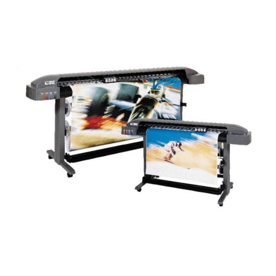
General Description Figure 1-1. Novajet PROe Series Inkjet Printers. Introduction This manual provides service information for the ENCAD , Inc. ® Novajet PROe Series Color Inkjet Printer. There are two ver- ® sions of the Novajet PROe printer: Novajet PRO 42e and Novajet PRO 60e. - Page 18 Both RS-422 serial and Centronics parallel connections are provided to interface with the host computer. Commands sent from the host computer can be in several forms including HP-RTL, and Encad RTL formats. Drivers are supplied to support Windows-based PC’s (3.XX, 95, and NT) as well as Macintosh and Power PC computers.
-
Page 19: Overview
• ENCAD, Inc. Novajet PROe User Guide, P/N 208713-1 Copies of this and other ENCAD, Inc. publications may be obtained by contacting your nearest authorized ENCAD, Inc. dealer or by contacting ENCAD’s Technical Support and Service Department. Electrostatic Discharge (ESD) Sensitivity... -
Page 20: Warnings, Cautions, And Notes
Novajet PROe Series Service Manual Warnings, Cautions, and Notes Warnings, cautions, and notes are used when additional informa- tion, instructions, or care should be observed. In this manual, warnings cautions, and notes precede the text to which each ap- plies. The definition of each is provided below. WARNINGS - Warnings are used to stress that the following steps or procedure has the potential to cause serious harm or death to service personnel. -
Page 21: Printer Specifications
Novajet PROe Series Service Manual Printer Specifications The specifications and performance characteristics of the Novajet PROe Color Inkjet Printers are as follows: Max Printing Area: Accuracy: PRO 42e PRO 60e 0.2% line length (with Norm 40.8” 58.8” ROLL mode off) 1.04m... -
Page 22: Contents Of This Service Manual
This manual is divided into six chapters as: Chapter 1 GENERAL DESCRIPTION - Contains a general description of the ENCAD Novajet PROe printer. This includes printer specifications, and related materials. Also included is a description of the use of Warnings, Cautions and Notes as used in this manual and chapter contents. - Page 23 Novajet PROe Series Service Manual Chapter 5 ASSEMBLY/DISASSEMBLY - Contains detailed procedures to remove and replace printer parts and assemblies. Chapter 6 PARTS LIST - Contains a complete listing of all field replacable parts and assemblies for the Novajet PROe Color Inkjet Printer. Illustrated parts breakdown drawings are included to help clarify and identify parts for ordering.
-
Page 24: Technical Support
Novajet PROe Series Service Manual Technical Support ENCAD offers full technical support and service for its various products. If you are unable to find the answer to your question in either the User’s Guide, Service Manual, or other related publica- tions, check out ENCAD’s Technical Bulletins located on ENCAD’s... -
Page 25: Chapter 2 Theory Of Operation
Theory of Operation Introduction This chapter explains the mechanical and electrical theory of opera- tion of the ENCAD Novajet PROe Series Color Inkjet printer. The Novajet PROe is a PowerPC 33MHz microprocessor-based digital printer that receives plotting instructions from a host com- puter through either the RS-422 serial interface or the Centronics parallel interface. -
Page 26: General Block Diagram
Novajet PROe Series Service Manual Figure 2-1. General Block Diagram. Theory of Operation... -
Page 27: Paper (Media) Axis Drive
Novajet PROe Series Service Manual Paper (Media) Axis Drive Figure 2-2. Paper (Media) Axis Drive. The Paper (Media) Axis Drive moves the plotting media in a direc- tion perpendicular to the length of the printer. This friction drive utilizes a micro-step drive technology and consists of a stepper motor, reduction gears, lower drive shaft assembly, and pinch wheels. -
Page 28: The Carrier Axis Drive
Novajet PROe Series Service Manual The Carrier Axis Drive Figure 2-3. Carrier Axis Drive. The Carrier Axis Drive moves the printer’s carrier assembly along the length of the printer. The drive consists of a servo motor, linear encoder strip, drive belt, and tensioning assembly. These items are illustrated in figure 2-3. -
Page 29: Media Feed And Take-Up System
Novajet PROe Series Service Manual Media Feed and Take-Up System Figure 2-4. Power Feed and Take-Up System. The media feed and take-up system comprises of two optical sensors and two dc motors. See Figure 2-4. The motors are used to advance the media feed roll and the media take-up roll dependant upon the signals they receive from the MPCB. -
Page 30: Main Printed Circuit Board (Mpcb)
Novajet PROe Series Service Manual Main Printed Circuit Board (MPCB) Figure 2-5. Main Printed Circuit Board. The Main Printed Circuit Board (MPCB) consists of six functional areas: Microprocessor (CPU) Gate Array Memory Circuits Stepper Motor Controller Servo Motor Controller Interface Circuits: Serial & Parallel Theory of Operation... -
Page 31: Microprocessor
Novajet PROe Series Service Manual Microprocessor The microprocessor (an IBM PowerPC) is the central processor unit which supervises system functions, executes the printer firmware, manipulates data, and controls input/output data busses. It has two built-in serial ports, a two channel DMA (Direct Memory Access) controller, a timer module, clock generator, and an on- board chip select generator. -
Page 32: Memory Circuits
Novajet PROe Series Service Manual The gate array contains the hardware logic for dot firing, monitoring changes in the Carrier Assembly position, controlling DMA through the parallel port, and generating the PWM (Pulse Width Modulation) waveforms for the servo controller. The gate array is a Xilinx device. - Page 33 Novajet PROe Series Service Manual The normal method of downloading new firmware is to send the printer a file of the new code. This requires using an appropriate host utility. This can be done through either the serial or parallel port.
-
Page 34: Stepper Motor Controller
Novajet PROe Series Service Manual Serial EEPROM Serial EEPROM is an Electrically Erasable, Programmable, Read Only Memory which provides storage for calibration constants and user configuration data entered from the host computer. An 8K bit serial non-volatile EEPROM stores calibration and con- figuration information. - Page 35 Novajet PROe Series Service Manual Each circuit contains four main blocks (see Figure 2-7): 1. Reference waveform generator The microprocessor uses a D/A (digital to analog) converter to set the desired level for the current in the stepper motor winding. The output of the D/A converter varies in time to create a refer- ence waveform.
-
Page 36: Servo Motor Controller
Novajet PROe Series Service Manual Servo Motor Controller Figure 2-8. Servo Motor Controller. The Carrier Assembly is driven by the Servo Motor. The speed of the Carrier Assembly is controlled by varying the duty cycle of the power applied to the controller. The microprocessor checks the position of the Carrier Assembly approximately 1,000 times per second (during the servo interrupt). -
Page 37: Quadrature Signal Generation
Novajet PROe Series Service Manual Figure 2-9. Quadrature Signal Generation. The direction that the Carrier Assembly is moving is known based upon the state of one detector’s output and the direction of the transition of the other detector’s output. A hardware counter in the gate array increments as the Carrier Assembly moves left and decrements as the Carrier Assembly moves right. -
Page 38: Interface Circuits: Serial & Parallel
The control signal can be configured as a 1MHz clock for high speed serial communications with a Macintosh. The serial port is compatible with RS-422 devices when an appropri- ate adapter cable is used. This cable is available from ENCAD. Theory of Operation... -
Page 39: Carrier Assembly Circuits
Novajet PROe Series Service Manual Carrier Assembly Circuits Figure 2-11. Carrier Assembly Circuits. The Carrier Assembly contains: 1) Carrier PCB 2) Optical Sensors 3) Paper Sensor 4) Inkjet Cartridges The Carrier PCB contains the logic and drive circuitry for the firing of the inkjet cartridges. -
Page 40: Keypad
Novajet PROe Series Service Manual The paper sensor circuitry senses for the presence of loaded media. It does this automatically during the start-up and load sequences. It also constantly monitors the media during printing to determine if the media has run out. If no paper is sensed, the paper sensor sends this information to the MPCB, which immediately begins an ‘out of paper’... -
Page 41: Power Supply
Novajet PROe Series Service Manual Figure 2-12 shows the keypad after the printer has been turned on and finished the start up process. As seen in the figure, the control buttons are assigned to the corresponding command that is dis- played closest to the physical location of the button. - Page 42 This fan provides suction on the platen bed and holds the paper (media) flat during the print- ing process. The PRO 60e version has an additional suction fan located near the center of the printer inside the platen.
-
Page 43: Chapter 3 Maintenance
Maintenance Introduction This chapter contains general maintenance and cleaning instruc- tions for the Novajet PROe series printers. Scheduled Maintenance Scheduled maintenance consists of a list of checks that are planned to be performed on a regular basis or when conditions warrant it. Scheduled maintenance can be thought of as preventive mainte- nance since its purpose is to prolong the life of the printer. -
Page 44: Cleaning Procedures
Novajet PROe Series Service Manual Cleaning Procedures Always turn the printer OFF, remove the power cord and the interface cable before cleaning the printer. An electrical shock hazard may be present if these proce- dures are not followed. External Cleaning Do not use abrasive cleansers of any sort on the sur- faces of the printer. -
Page 45: Service Station Cleaning
Novajet PROe Series Service Manual Printer problems can be caused by an accumulation of dirt or other contamination on the slide shaft. This contamination may lead to drag on the carrier. Extreme drag results in a “carrier axis failure” fault and will stop the carrier motion. These problems may be eliminated by maintaining and cleaning the slide shaft at intervals determined by the environmental conditions. -
Page 46: Linear Encoder Strip Cleaning
Novajet PROe Series Service Manual 4. Using a cotton swab dampened with distilled water, wipe the seals and the rubber wiper in the service station until no more ink residue or dust can be removed. 5. With a dry swab, wipe all moisture from the seals and wipers. 6. -
Page 47: Cartridge Dimples Cleaning
Novajet PROe Series Service Manual Cartridge Dimples Cleaning Figure 3-2. Cartridge Dimple Region. The cartridge dimple area can easily be contaminated by oils and dirt on fingers and hands or ink spilled onto them. This causes the cartridges to not receive some of the electrical signals for a proper firing of the jets. -
Page 48: Flex Cable Contact Cleaning
Novajet PROe Series Service Manual Flex Cable Contact Cleaning Figure 3-3. Flex Cable Contacts. Cleaning the flex cable contact area is very important due to the ease of which this area can become dirty. This also causes the cartridges to not receive all of the electrical signals for a proper firing of the jets. -
Page 49: Clean And Inspect Mpcb
Novajet PROe Series Service Manual reduce the quality of the intended output. Clean the motor gears with a stiff brush to knock off any debris. A cotton swab soaked isopropyl alcohol can be used to remove any ink that may have accumulated on the gears. -
Page 50: Reseat Connectors On Mpcb And Carrier Board
Novajet PROe Series Service Manual Reseat Connectors on MPCB and Carrier Board Integrated circuits may become weakened or damaged by electrical discharge. Do not touch or work near in- tegrated circuits without wearing an ESD wrist strap. Ribbon connectors can be easily damaged if incorrectly handled. -
Page 51: Mpcb Connection Locations
Novajet PROe Series Service Manual Figure 3-4. MPCB Connection Locations. Figure 3-5. Carrier Connection Locations. Maintenance... -
Page 52: Replace Carrier Bushings
Novajet PROe Series Service Manual Figures 3-4 and 3-5 shows the locations of all the connectors on the MPCB and carrier board respectively. To remove the ribbon cables from their connectors, lift the connector’s ribbon locking mechanism as shown in figure 3-6. To reattach, depress the locking mechanism back into the locking position after inserting the ribbon cable end. -
Page 53: Servo Motor Winding Resistance Check
Novajet PROe Series Service Manual Servo Motor Winding Resistance Check Figure 3-7. Servo Motor. 1. Disconnect the servo motor connection from the MPCB. 2. Using a standard ohmmeter or multimeter, connect the meter leads to the two wires going to the motor. 3. -
Page 54: Stepper Motor Winding Resistance Check
Novajet PROe Series Service Manual Stepper Motor Winding Resistance Check Figure 3-8. Stepper Motor. 1. Disconnect the stepper motor connection from the MPCB. 2. Using a standard ohmmeter or multimeter, measure between pins 1 (red wire) and 3. 3. The reading should indicate 7.2-8.0 ohms. 4. -
Page 55: Power Feed And Take-Up Motor Winding Resistance Check
Novajet PROe Series Service Manual Power Feed and Take-Up Motor Winding Resistance Check Figure 3-9. Power Feed and Take-Up Motor. 1. Remove the feed and/or take-up roll from the printer. 2. Using Phillips screwdriver, remove the four screws that secure the cradle idler from the right leg. 3. -
Page 56: Banding: Hardware Vs Software
RIP, if used. To eliminate the chance that it is the printer driver: 1) Remove any RIP or network systems and connect the printer directly to the computer. 2) Print a test file approved by ENCAD that uses only the printer driver software and the ENCAD printer. Maintenance... -
Page 57: Alignments/Adjustments
If the test file prints correctly, the problem lies in either the soft- ware package that generated the print or the RIP, if used. Alignments/Adjustments The ENCAD Novajet PROe Series printers are designed with a minimum of maintenance requirements in mind. Calibrations include: color calibration, deadband alignment, and X-axis calibra- tion. -
Page 58: Dial Gauge Micrometer Assembly
Novajet PROe Series Service Manual There are two basic measurements that are to be made using this kit (ensure power is off prior to performing these procedures): 1. Slide Shaft Profile Adjustment 2. Carrier (Cartridge) Head Height Setting 1. Connect the dial gauge micrometer to the Shaft mounting block as shown in Figure 3-11. -
Page 59: Slide Shaft Profile Adjustment
(the value found in step 3.) See Figure 3-13. NOTE The Novajet PRO 60e has two turnbuckles, so these need to be adjusted together for the center position. Figure 3-13. Slide Shaft Profile Adjustment. Maintenance... -
Page 60: Head Height Alignment Procedure
Novajet PROe Series Service Manual For example: If the Left = 0, Right = +0.004”, then the Center should be adjusted to + 0.002”. This will ensure a smooth plane of travel for the carriage assembly. There are no adjustments on either end of the shaft in all models. -
Page 61: Setting Up Tools From Height Gauge Kit
Novajet PROe Series Service Manual Figure 3-15. Setting Up Tools from Height Gauge Kit. 3. Place the test cartridge upright on a flat surface and ‘zero’ the gauge by loosening the knob near the top and turning the dial until the needle is at the ‘0’ position on the dial. Tighten the knob. -
Page 62: Test Cartridge Installed
Novajet PROe Series Service Manual Figure 3-17. Test Cartridge Installed. 5. Slightly loosen the screws located on the back of the Y-arm that secures the stabilizer to the Y-arm. Damage may occur to the micrometer gauge if the Carrier is moved without lifting up on the measuring tip. -
Page 63: Color Calibration
Novajet PROe Series Service Manual NOTE The measurement of 0.075” instead of 0.065” as stated earlier is used due to the fact that the test cartridge does not contain a jet plate assembly. A 0.010” differ- ence had to be added to compensate for the lack of a jet plate assembly on the test cartridge. -
Page 64: Color Calibration
Figure 3-18. Color Calibration. The “Current Heads (Y, M, C)” view represents the alignment of the heads as they are currently entered. This is just an overview of all heads and how they are aligned. Do not attempt to align the heads using this view. -
Page 65: Utility Menu
Novajet PROe Series Service Manual To perform the Color Calibration: 1. Select “Utility Menu” from the Main Menu. This brings up the Utility Menu as shown in Figure 3-19. Figure 3-19. Utility Menu. 2. From the Utility Menu, select “Color Calib Menu”. This brings up the color calibration menu and it looks like Figure 3-20. -
Page 66: Deadband Alignment
4. When the plot is complete, select “Cyan Vertical” at the Color Calib Menu. This brings up the options menu for the cyan vertical adjustment as shown in Figure 3-21. Figure 3-21. Cyan Vertical Options Menu. 5. Observe the plot and using either “Prev Option” or “Next Option”, rotate through the selections until the one that best aligns the cyan color on the plot is selected. -
Page 67: Service Menu
Novajet PROe Series Service Manual Figure 3-22 shows what the display will look like when printing either the fast or slow test if it is out of alignment. A correctly aligned printer will appear as if there is only a series of vertical lines printed. -
Page 68: Calibration (Deadband) Menu
3. Select the “Calibration Menu” from the Service Menu. 4. The Calibration Menu is shown in Figure 3-24 and is where all the deadband tests are performed. Select “Deadband Test” to perform the fast deadband test. Figure 3-24. Calibration (Deadband) Menu. 5. -
Page 69: Paper Axis Calibration
Novajet PROe Series Service Manual 7. Continue performing steps 4 through 6 until the fast deadband adjustment is correct. 8. At the Calibration Menu, select “Slow Db Test” to run the slow deadband test. 9. When the plot is complete, select “Slow Deadband” at the Service Menu. -
Page 70: Calibration Menu
Figure 3-25. Calibration Menu. 3. From the Calibration Menu, select “Paper Axis Test”. This runs the paper axis test which prints out two “T” figures that are mirrored from each other and about 33” apart. See Figure 3-26. Figure 3-26. Paper Axis Test. -
Page 71: Diagnostics Menu
Novajet PROe Series Service Manual 4. With a precision drafters measuring stick, measure the exact distance from each of the “T” intersections. 5. Select “Paper Axis” at the Calibration Menu. This brings up the options menu for the paper axis adjustment. This menu is similiar to the menu depicted in Figure 3-21. -
Page 72: Accessory Menu
Figure 3-28. Accessory Menu. Servo PWM Test - Monitors the PWM (pulse width modulation) signal applied to the servo motor from the driver on the MPCB to check the amount of force required to move the Carrier. The test includes three complete cycles of the carrier assembly and lists the average PWM, the maximum PWM, and the position of the carrier where the maximum PWM occured. -
Page 73: Limited Access Menu
Novajet PROe Series Service Manual The Continuous Test will first prime the cartridges, followed by a serial port test, parallel port test, and a fast deadband display. The daedband display is used only as a visual inspection of the operating condition of the printer. No adjustments can be performed while in the Continuous Test mode. -
Page 74: Nvram Clear And Clock Reset Menu
Figure 3-29. NVRAM Clear and Clock Reset Menu. This menu allows the technician to clear the NVRAM and to reset the system clock. Clear NVRAM - Clearing the NVRAM is required anytime that a MPCB is to be permanently removed from a printer. The NVRAM is a section of nonvolatile memory that stores printer size informa- tion. -
Page 75: Firmware Downloading
Novajet PROe Series Service Manual Firmware Downloading The normal method of downloading new firmware is to send the printer a data file of the new code. This requires using an appro- priate host utility called “go.exe.” This must be done through the parallel port using a IEEE standard 1284 parallel cable. -
Page 76: Internal Cabling And Signal Flow Diagrams
3) At the computer, type “GO ROMIMAGE” from the directory that contains the GO.EXE and ROMIMAGE files. 4) In about 15 - 60 seconds, a single beep will be heard from the printer to signify a good transfer of data. If a beep is not heard, cycle the power on the printer and send the file again. -
Page 77: Mpcb Connections Diagram
Novajet PROe Series Service Manual Figure 3-31. MPCB Connections Diagram. Maintenance... -
Page 78: Carrier Pcb Connections Diagram
Figure 3-32. Carrier PCB Connections Diagram. -
Page 79: Leg Harness Connections Diagram
Novajet PROe Series Service Manual Figure 3-33. Leg Harness Connections Diagram. Maintenance... - Page 80 This Page Intentionally Left Blank...
-
Page 81: Chapter 4 Troubleshooting
Troubleshooting Introduction Chapter 4, Troubleshooting consists of a table that is intended to aide the technician in troubleshooting the Novajet PROe printers. This table addresses symptoms with their possible causes and solutions. Basic troubleshooting skills will be required to perform the symptom identification, troubleshooting, fault isolation, and repair of the printer when using this table. -
Page 82: Media Does Not Move
Novajet PROe Series Service Manual Table 4-1. Troubleshooting Table (cont). Symptoms Possible cause Solution No Power (cont) • all DC output replace power voltages not supply present (see Figure 3-30 for voltages) • all DC voltages replace MPCB present at MPCB Media Does Not Move •... -
Page 83: Internal Error "Carriage Axis Failure
Novajet PROe Series Service Manual Table 4-1. Troubleshooting Table (cont). Symptoms Possible cause Solution Internal ERROR “Carriage Axis Failure” • dirty (or perform Slide Shaft lubricated) slide Cleaning procedure shaft • perform Servo replace servo motor Motor Winding Resistance check •... -
Page 84: Internal Error "Encoder Sensor Failure
Novajet PROe Series Service Manual Table 4-1. Troubleshooting Table (cont). Symptoms Possible cause Solution Internal ERROR • cutter assembly replace cutter “Carriage Axis malfunction assembly Failure” (cont) • damaged carrier 1) check idler/ drive belt system tension assembly 2) check carrier belt Internal ERROR “Encoder Sensor Failure”... -
Page 85: Internal Error "Trailing Cable Failure
Novajet PROe Series Service Manual Table 4-1. Troubleshooting Table (cont). Symptoms Possible cause Solution Internal ERROR “Trailing Cable Failure” • trailing cable power down and cable unseated reseat trailing cable • bad paper replace paper sensor sensor Internal ERROR “MPCB Failure” •... - Page 86 Novajet PROe Series Service Manual Table 4-1. Troubleshooting Table (cont). Symptoms Possible cause Solution Ink Cartridge • flex contacts 1) perform Flex Misfiring (cont) dirty or damaged Cable Contact Cleaning procedures 2) replace carrier assembly • cartridge dimple 1) perform area dirty or Cartridge Dimple damaged...
-
Page 87: Paper Skewing
Novajet PROe Series Service Manual Table 4-1. Troubleshooting Table (cont). Symptoms Possible cause Solution Paper Skewing • paper guides not install paper installed guides • stepper motor perform Clean and gearing dirty or Inspect Stepper damaged Motor Gears procedure Printer Output is Banding •... -
Page 88: Keypad Locked-Up Or Not Functioning Properly
Novajet PROe Series Service Manual Table 4-1. Troubleshooting Table (cont). Symptoms Possible cause Solution Printer Output is • cartridge dimple 1) perform Banding (cont) area dirty or Cartridge Dimple damaged Cleaning procedure 2) replace cartridge • flex cable 1) perform Flex contacts dirty or Cable Contact damaged... -
Page 89: Noisy Operation
Novajet PROe Series Service Manual Table 4-1. Troubleshooting Table (cont). Symptoms Possible cause Solution Noisy Operation • ink or paper clean printer debris in printer • obstruction in remove obstruction/ path of carrier clean printer • carrier bushings replace carrier worn bushings •... -
Page 90: Line Quality Degraded
Novajet PROe Series Service Manual Table 4-1. Troubleshooting Table (cont). Symptoms Possible cause Solution Line Quality De- graded • ink cartridges clean and prime dirty or clogged ink cartridges • cartridge dimple clean or replace region dirty or cartridge damaged •... -
Page 91: Fan Does Not Power Up
Novajet PROe Series Service Manual Table 4-1. Troubleshooting Table (cont). Symptoms Possible cause Solution Line Quality • drive belt replace frame Degraded (cont) slipping on idler tensioner, spring, or idler • vacuum fan not replace fan operating assembly Fan Does Not Power Up •... -
Page 92: Media Feed Motor Not Operating, Sensor Works
Novajet PROe Series Service Manual Table 4-1. Troubleshooting Table (cont). Symptoms Possible cause Solution Media Feed Motor Not Operating, Sensor Works • bad connection reconnect Feed to the motor motor • bad Feed motor Replace Feed motor • faulty wiring leg reseat or replace harness leg harness... -
Page 93: Media Feed Or Take-Up Sensor(S) Not Operating
Novajet PROe Series Service Manual Table 4-1. Troubleshooting Table (cont). Symptoms Possible cause Solution Media Feed or Take-Up Sensor(s) Not Operating • reflective decal clean decal and/or is dirty or blocked clear obstruction • reflective decal replace reflective missing decal •... - Page 94 Novajet PROe Series Service Manual This Page Intentionally Left Blank Troubleshooting...
-
Page 95: Chapter 5 Assembly\Disassembly
Assembly\Disassembly Introduction Chapter 5 contains the procedures for removal and replacement of the NOVAJET PROe series printer assemblies and mechanisms. Illustrations are provided for clarity. Steps for each replaceable part may depend on parts already removed in previous disassembly directions. It is recommended that you read through each proce- dure before beginning the removal and replacement of any assem- blies or mechanisms. -
Page 96: Remove The Left, Top, And Right Covers
Novajet PROe Series Service Manual Always turn the printer OFF, remove the power cord and the interface cable before beginning any disas- sembly procedures. An electrical shock hazard may be present if these precautions are not followed. Remove the Left, Top, and Right Covers Removing the Left Cover allows access to the left side of the Platen for removal of the Carrier Assembly, Carrier Drive Belt, Tension Assembly, and the Cutter Activator. -
Page 97: Right Cover Assembly Removal/Installation
Novajet PROe Series Service Manual 3. Lift up on the left side of the Top Cover until it clears the Left Cover while still depressing the retracting stop assembly, then slide the cover to the left to disengage it from the Right Cover. To remove the Right Cover Assembly: Figure 5-1. -
Page 98: Left Cover Assembly Removal/Installation
Novajet PROe Series Service Manual 9. Disconnect the Display Power Converter connector at the J10 location on the MPCB. To disconnect, grasp the Display Power Converter connector between thumb and forefinger and pull straight out. To remove the Left Cover Assembly: 10. -
Page 99: Install The Left, Top, And Right Covers
Novajet PROe Series Service Manual Install the Left, Top, and Right Covers To install the Left Cover Assembly: 1. Position the Left Cover Assembly over the Left Baseplate and while depressing the retracting stop assembly on the Support Bracket, lower the Left Cover into position onto the Left Baseplate. -
Page 100: Remove The Keypad, Display, And Display Power Converter
Novajet PROe Series Service Manual Applying too much torque to the lower screws can cause the mounts for the standoffs on the cover to break, requiring a replacement of the cover. 8. Using a #2 Phillips screwdriver, secure the Right Cover with two screws located on the left side (torque to 15 in-lbs) and three located under the baseplate (torque to 8 in-lbs.) To install the Top Cover:... - Page 101 Novajet PROe Series Service Manual Figure 5-3. Keypad and Display Installation/Removal. 2. Turn the Right Cover Assembly over and disconnect the Display power cable located at J13 from the Display Power Converter. With a 1/4” socket or wrench, remove the four kepnuts securing the Display Power Converter.
-
Page 102: Install The Keypad, Display, And Display Power Converter
Novajet PROe Series Service Manual Figure 5-4. Keypad Grounding Connection. Install the Keypad, Display, and Display Power Converter 1. Route the Keypad flex data and ground cables into the Right Cover Assembly through the hole provided for the Keypad. 2. Place the Keypad into position and hold. Turn the Right Cover Assembly over and position the Display Assembly onto the threaded studs of the Keypad. -
Page 103: Remove Extra Memory (Simm)
Novajet PROe Series Service Manual Remove Extra Memory (SIMM) Integrated circuits may become weakened or dam- aged by electrical discharge. Do not touch or work near integrated circuits without wearing an ESD wrist strap. 1. Perform steps 1 through 9 of the Remove the Left, Top, and Right Covers procedure to remove the Top and Right Covers. -
Page 104: Install Extra Memory (Simm)
Novajet PROe Series Service Manual Install Extra Memory (SIMM) NOTE If you are installing two SIMM, you must install the one located in J17 first. See Figure 3-4 for location. 1. The SIMM slots are at a 90° angle from the board. Place the SIMM at a 45°... - Page 105 10. Disconnect the Vacuum Fan 2 connection at the J6 location (Pro 60e version only) by grasping the Vacuum Fan 2 connector with thumb and forefinger and pulling straight out. 11. Disconnect the Trailing cable connection at the J7 location.
-
Page 106: Mpcb Removal
MPCB and af- fect the Warranty. 15. Place the MPCB in an ESD bag (antistatic bag) in preparation for shipment to ENCAD for replacement or repair, or if it is to be stored at your facility for repair. Assembly\Disassembly... -
Page 107: Install The Mpcb
6. Connect and lock the Trailing Cable connector to J7 on the MPCB. 7. Connect the Vacuum Fan 2 (PRO 60e only) connector to J6 on the MPCB. 8. Connect the Vacuum Fan 1 connector to J5 on the MPCB. -
Page 108: Remove Power Supply, Cooling Fan, And Ac Entry Module
Novajet PROe Series Service Manual 13. Connect the Power Supply connector to J15 on the MPCB. 14. Reinstall any additional memory into J17 by performing steps 1 and 2 of the Install Extra Memory (SIMM) procedure. 15. Perform steps 4 through 10 of the Install the Left, Top, and Right Covers procedure to install the Right and Top Covers. -
Page 109: Power Supply Removal
Novajet PROe Series Service Manual Figure 5-7. Power Supply Removal. To remove the Cooling Fan and AC Entry Module: 7. Using a #2 Phillips screwdriver, remove the four screws located below the Right Baseplate securing the Power Supply Bracket to the Right Baseplate. Remove the Power Supply Bracket. -
Page 110: Install The Power Supply, Cooling Fan, And Ac Entry Module
Novajet PROe Series Service Manual Figure 5-8. Cooling Fan/AC Entry Module Removal. 8. Using a 1/4” wrench or socket, disconnect the AC Entry Module ground from the ground stud on the Right Baseplate. 9. Remove the AC Entry Module by pressing in on the securing tabs until the module is released. -
Page 111: Remove Servo Motor
Novajet PROe Series Service Manual 6. Reconnect the Power Supply to the AC Entry Module by reattaching the quick disconnect connection. Push the quick disconnect assembly behind the Power Supply Bracket and out of sight. 7. Perform steps 1 through 14 of the Install the MPCB procedure to install the MPCB. -
Page 112: Slacken Carrier Belt
Novajet PROe Series Service Manual Figure 5-9. Slacken Carrier Belt. 6. Remove the Right Sideplate to gain access to the Servo Motor by unscrewing the four screws securing it to the Platen. 7. Depress the back of the Frame Tensioner (see Figure 5-9) to create slack in the Carrier Belt and slip it off of the Servo Motor pulley. -
Page 113: Install Servo Motor
Novajet PROe Series Service Manual 14. Lower the motor to clear the pulley assembly from the platen and carefully bring the motor out of the printer. Install Servo Motor 1. Reinsert the Servo Motor under the Platen with the connector facing the FRONT side of the Platen. Guide the pulley up through the opening in the Platen. -
Page 114: Remove The Ink Delivery System
Left Covers. NOTE The Foam Chain Shelf being removed in step 2 is only on the PRO 60e printers. 2. Remove the Foam Chain Shelf located inside the rear support bracket. 3. Move the Carrier to the center of the Slide Shaft. -
Page 115: Electronics Cover Removal
Novajet PROe Series Service Manual Figure 5-10. Electronics Cover Removal. 4. With a flathead screwdriver, press the Electronics Cover (p/o the Ink Delivery System) tab located in the upper slot on the left side of the Carrier Assembly. See Figure 5-10. Lift up on the front left side of the Electronics Cover until it comes part way off of the Carrier Assembly. -
Page 116: Disconnect Ink Delivery System Link
Novajet PROe Series Service Manual Figure 5-11. Disconnect Ink Delivery System Link. NOTE The last link of the Ink Delivery System linkage is a special link and is to remain as part of the Left Sideplate Assembly. It is mounted to the Sideplate Assembly and will not be delivered as part of the Ink Delivery System. -
Page 117: Install The Ink Delivery System
Cover and lower the Assembly onto the Carrier until it snaps into place. 5. Place the Foam Chain Shelf in the Support Bracket (PRO 60e only.) Align the left side of the Shelf to the center of the leftmost pinch roller. -
Page 118: Strain Relief Removal/Installation
Novajet PROe Series Service Manual Figure 5-12. Strain Relief Removal/Installation. 5. Remove the Trailing Cable and Strain Relief from the Carrier Assembly by releasing the latch on the left lower side of the Strain Relief and lifting it off of the Carrier Assembly. See Figure 5-12. -
Page 119: Frame Tensioner
Novajet PROe Series Service Manual Figure 5-13. Frame Tensioner. 9. Slide the Carrier Assembly and Drive Belt off the left side of the Slide Shaft. 10. Once the Carrier Assembly is removed from the Slide Shaft, turn it over so that you can see the Belt Clamp. See Figure 5-14. -
Page 120: Install The Carrier Assembly, Carrier Belt, And The Frame Tensioner
Warranty. 13. Place the Carrier Assembly in an ESD (antistatic) bag in preparation for shipment to ENCAD for replacement or repair, or if it is to be stored for repair at your facility. Install the Carrier Assembly, Carrier Belt, and the Frame Tensioner 1. - Page 121 Novajet PROe Series Service Manual 5. Slide the Carrier Assembly onto the left end of the Slide Shaft, making sure that the Encoder Strip fits into the slot in the Slider and the Encoder on the Carrier PCB. Guide the belt while sliding the Carrier Assembly from left to right on the Slide Shaft.
-
Page 122: Remove The Carrier Pcb
Novajet PROe Series Service Manual 15. Fit the Compression Spring over the post at the back of the Y- Arm Assembly. 16. Fit the notch in the front end of the Frame Tensioner over the notch in the front of the Y-Arm Assembly. 17. -
Page 123: Carrier Pcb Removal/Installation
Novajet PROe Series Service Manual Figure 5-15. Carrier PCB Removal/Installation. 4. Unlock the latch on the right end of the Carrier Assembly and lift up the right end of the Carrier PCB. See Figure 5-15. 5. Slide the Carrier PCB to the right to remove the tab on the left end of the Carrier PCB from the slot in the Carrier Assembly. -
Page 124: Install The Carrier Pcb
Warranty. 6. Place the Carrier PCB in an ESD bag (antistatic bag) in preparation for shipment to ENCAD for replacement or repair, or if it is to be stored at your facility for repair. Install the Carrier PCB 1. -
Page 125: Paper And Encoder Sensor Removal
Novajet PROe Series Service Manual Figure 5-16. Paper and Encoder Sensor Removal. 2. To remove the Paper Sensor: a. Unlock the connector at J3 and remove the flex cable. b. Turn the Carrier Assembly over and hold it while firmly grasping the Paper Sensor between thumb and index finger. -
Page 126: Install The Paper Sensor Or The Encoder Sensor
Novajet PROe Series Service Manual c. Push down on the plastic clip and at the same time push down on the Encoder until the plastic pieces on each side of the Encoder clear the ridges which hold it in place. Then pull it straight out. -
Page 127: Replacing The Carrier Bushings
Novajet PROe Series Service Manual Push both sides of the connector lock shut at the same time. 2. To install the Encoder Sensor: a. Turn the Carrier Assembly so that the bottom side of it is facing up. b. Push down on the plastic clip and slide the back of the Encoder Sensor over it. -
Page 128: Carrier Bushing Removal
Novajet PROe Series Service Manual Figure 5-18. Carrier Bushing Removal. 2. Use a flat tip screwdriver to push up on the latch which holds the Carrier Bushing in place. See Figure 5-18. 3. Pull the Carrier Bushing out of the Carrier Assembly. 4. -
Page 129: Remove The Service Station, Seals, And Wipers
Novajet PROe Series Service Manual Remove the Service Station, Seals, and Wipers Figure 5-20. Service Station, Exploded View. 1. Place the Top Cover in the open position. 2. Move the Carrier Assembly to the left side of the Slide Shaft. 3. -
Page 130: Install The Service Station, Seals, And Wipers
Novajet PROe Series Service Manual 4. Raise the right side of the Service Station out of the Platen. 5. Lift out the left side of the Service Station from the Platen and remove the Service Station. Moving the Service Station farther to the right might be required to release the left side of the Service Station. -
Page 131: Remove The Trailing Cable Assembly
Novajet PROe Series Service Manual Reattach the spring onto the post on the bottom of the Service Station Sled. 2. To install a Service Station Wiper, press the new Wiper onto the wiper support. 3. Position the Service Station inside the Right Cover and place the left side of the Service Station into the Platen. -
Page 132: Install The Trailing Cable Assembly
Novajet PROe Series Service Manual Install the Trailing Cable Assembly 1. Apply two new pieces of double sided tape to the Stabilizer Bracket. Ensure that the tape is in the same location as the original tape was. The right side of the Trailing Cable (the side connected to the MPCB) must extend beyond the Stabilizer Bracket by 5”... -
Page 133: Remove The Stabilizer Bracket And Encoder Strip
Novajet PROe Series Service Manual 7. If the Carrier Assembly is installed, insert the Trailing Cable Assembly into the Strain Relief Assembly. Insert the Strain Relief (with Trailing Cable) onto the Carrier Assembly by sliding it onto the Strain Relief Support until it snaps firmly into place. -
Page 134: Stabilizer Bracket Installation/Removal
Novajet PROe Series Service Manual Figure 5-21. Stabilizer Bracket Installation/Removal. 6. Remove the Stabilizer Bracket from the Y-Arm Assembly by removing the four alignment Allen screws and washers located on the back of the Y-Arm Assembly. The Encoder Strip is not a field removable item. The entire Stabilizer Bracket Assembly with the Encoder Strip and Trailing Cable installed is to be replaced if the Encoder Strip is damaged. -
Page 135: Install The Stabilizer Bracket And Encoder Strip
Novajet PROe Series Service Manual Install the Stabilizer Bracket and Encoder Strip 1. Install the Stabilizer Bracket Assembly (with Encoder Strip and Trailing Cable) onto the Y-Arm Assembly using the four alignment Allen screws and washers. Hand tighten only. 2. Install the Support Bracket onto the Stabilizer Bracket Assembly by placing the Support Bracket onto the Stabilizer Bracket with a slight forward tilt. -
Page 136: Y-Arm Installation/Removal
Novajet PROe Series Service Manual 4. Perform steps 3 and 4 of the Remove the Trailing Cable Assembly procedures to remove the Trailing Cable Assembly. 5. Perform steps 5 and 6 of the Remove the Stabilizer Bracket and Encoder Strip procedures to remove the Stabilizer Bracket Assembly. -
Page 137: Install The Y-Arm Assembly, Pinch Rollers, Slide Shaft, And Auto-Load Sensor
Novajet PROe Series Service Manual Figure 5-23. Pinch Roller. 9. Spin the back of the pinch roller to either side and remove the back spring. 10. Carefully tilt the back of the pinch roller upwards. This brings the front of the pinch roller down, away from the Slide Shaft. Carefully remove the spring that is going into the Slide Shaft from the top of the pinch roller. - Page 138 Novajet PROe Series Service Manual 2. Route the Load Sensor wires through the four wire clamps on the back part of the Y-Arm Bracket. 3. Install the Slide Shaft and two supports to the Y-Arm Assembly using four screws. Torque to 8 in-lbs. 4.
-
Page 139: Remove The Lower Roller Assembly, Stepper Motor And Vacuum Fan
Novajet PROe Series Service Manual Remove the Lower Roller Assembly, Stepper Motor and Vacuum Fan The Inner Platen contains the Lower Drive Roller Assembly, the Vacuum Fan Assembly, the Stepper Motor Assembly, Drive Shaft Supports, and the Foam Block. These parts are collectively referred to as the Inner Platen Parts. -
Page 140: Inner Platen Assembly/Disassembly
5-24. NOTE The Novajet PRO 42e printer has one Vacuum Fan and Exhaust assembly while the 60e has two sets of Vacuum Fans and Exhausts. 7. Using a #1 Phillips screwdriver, remove the four screws on the bottom of the Platen which holds the Fan Exhaust(s) in place. - Page 141 Novajet PROe Series Service Manual 9. Using a #1 Phillips screwdriver, remove the black flat-head screws from the top of the Platen that holds the left and right Drive Shaft Supports in place. It may be necessary to loosen (do not remove) the screws that secure the Y-Arm Assembly to the Platen so that the Lower Drive Roller Assembly clears the ends of the screws that protrude inside of the Platen...
-
Page 142: Install The Lower Roller Assembly, Stepper Motor And Vacuum Fan
Novajet PROe Series Service Manual 11. Remove the Stepper Motor Extension Spring from the Stepper Motor and the post on the Left Lower Drive Shaft Bracket. See Figure 5-25. Figure 5-25. Stepper Motor Removal/Installation. 12. Remove the hardware securing the Stepper Motor to the Left Lower Drive Shaft Bracket and remove the Stepper Motor. - Page 143 Continue to insert the Lower Drive Roller Assembly into the Platen. 5. Position and hold the other Fan Assembly (for PRO-60e only) under the Lower Drive Roller Assembly and between the seventh and last rollers. Continue to insert the Lower Drive Roller Assembly completely into the Platen.
-
Page 144: Inside Platen, Right Side
Novajet PROe Series Service Manual 8. Install the Lower Drive Roller Assembly support brackets using a #2 Phillips screwdriver. 9. Reinsert the Foam Block. Make sure that the Stepper Motor and Fan(s) cables are exiting out of the back corner of the Foam Block. -
Page 145: Remove The Media Take-Up And Feed Sensor Brackets And Sensors
Novajet PROe Series Service Manual 14. Perform steps 5 through 14 of the procedures to reconnect the MPCB. 15. Reinstall the Left Baseplate using a #2 Phillips screwdriver. 16. Reinstall the Left Sideplate using a #2 Phillips screwdriver. 17. Perform steps 1 through 4 of the Install the Ink Delivery System procedures to reinstall the Ink Delivery System. -
Page 146: Install The Media Take-Up And Feed Sensor Brackets And Sensors
Novajet PROe Series Service Manual Figure 5-27. Media Take-Up and Feed Sensor Removal. Install the Media Take-Up and Feed Sensor Brackets and Sensors 1. Using a #2 Phillips screwdriver, install the two screws securing the bracket to the leg assembly. 2. -
Page 147: Remove The Media Take-Up And Feed Motors
Novajet PROe Series Service Manual Remove the Media Take-Up and Feed Motors 1. Remove all media and media rollers from the printer. 2. Remove the four screws holding the Cradle Idler to the leg assembly. See Figure 5-28. 3. Carefully slide the Cradle Idler assembly out of the leg assembly until the wires going to the motor can be removed. -
Page 148: Install The Media Take-Up And Feed Motors
Novajet PROe Series Service Manual Install the Media Take-Up and Feed Motors 1. Using a #1 Phillips screwdriver, install the three screws, washers, and lock washers that secures the motor to the motor mount. 2. Install the motor gear to the motor. Secure with a C clamp. 3. -
Page 149: Remove The Media Drying Fans
Novajet PROe Series Service Manual Figure 5-28. Media Take-Up and Feed Motor Removal. Remove the Media Drying Fans 1. On the left side of the drying fan assembly is a black wingnut used to adjust the position of the fan assembly. Remove the black wingnut. -
Page 150: Install The Media Drying Fans
Novajet PROe Series Service Manual the tabs on the filter housing to release the housing off the fan. 5. Remove the four bolts securing the back bracket (the one with the positioning bolts on the bottom) to both of the side plates. 6. -
Page 151: Chapter 6 Parts List
This list is to be used in conjunction with the assembly/disassembly procedures to aquire the necessary parts and properly install them into the printer. The parts and asssemblies may be ordered through your local autho- rized dealer or ENCAD, Inc.’s Technical Support and Service department. FIGURE ITEM PART NAME PART # COVER, LEFT ......... - Page 152 MAIN PRINTED CIRCUIT BOARD ..207624 POWER SUPPLY ASSEMBLY ....207618 MOTOR ASSY, SERVO ......207517 STEPPER MOTOR ASSY ...... 209071 FAN ASSEMBLY, VACUUM ....203443 EXHAUST, GRILL ......... 204976 LOWER ROLLER ASSY, 60e ....207023 LOWER ROLLER ASSY, 42e ..... 207506...
- Page 153 Novajet PROe Series Service Manual FIGURE ITEM PART NAME PART # INK DELIVERY SYSTEM, 60e ..... 207613-1 INK DELIVERY SYSTEM, 42e ..207613-2 CARTRIDGE TUBE ASSY, BLUE ..207614 CARTRIDGE TUBE ASSY, GRAY ..207615 CARRIER PCB ........207469 STRAIN RELIEF ........208276 ENCODER SENSOR W/FLEX ....
-
Page 154: Left Side Parts Breakdown
Figure 6-1. Left Side Parts Breakdown. -
Page 155: Platen And Above Parts Breakdown
Novajet PROe Series Service Manual Figure 6-2. Platen and Above Parts Breakdown. Parts List... -
Page 156: Right Side Parts Breakdown
Figure 6-3. Right Side Parts Breakdown. -
Page 157: Inner Platen Parts Breakdown
Novajet PROe Series Service Manual Figure 6-4. Inner Platen Parts Breakdown. Parts List... -
Page 158: Carrier Assembly Parts Breakdown
Figure 6-5. Carrier Assembly Parts Breakdown. -
Page 159: Power Feed And Take-Up Parts Breakdown
Novajet PROe Series Service Manual Figure 6-6. Power Feed and Take-Up Parts Breakdown. Parts List... - Page 160 This Page Intentionally Left Blank...
-
Page 161: Index
Index general block diagram . . 25 adapter J Tag . . 75 alignments head height . . 60 ink delivery system . . 114 slide shaft . . 57 axis drive carrier . . 28 jack paper (media) . . 27 connections carrier . - Page 162 . . 82 no power . . 81 noisy operation . . 89 paper skewing . . 87 technical support ENCAD BBS . . 24 ENCAD website . . 24 help desk vacuum fan . . 139 FAX # . . 24 telephone # .
Need help?
Do you have a question about the 60e and is the answer not in the manual?
Questions and answers