Table of Contents
Advertisement
Advertisement
Table of Contents
Troubleshooting

Subscribe to Our Youtube Channel
Related Manuals for ENCAD ENCAD T200+


Summary of Contents for ENCAD ENCAD T200+
- Page 1 SERVICE MANUAL...
-
Page 2: Service Manual
® T-200 T-200+ COLOR INKJET PRINTER/PLOTTERS SERVICE MANUAL Part Number 219863-00... - Page 3 ENCAD T-200 and T-200+ Service Manual Copyright Eastman Kodak Company, 2002 ® ® KODAK, ENCAD and CadJet are trademarks of Eastman Kodak Company. Other trademarks and registered trademarks are the property of their respective owners. Except as provided below, no part of this manual may be...
-
Page 4: User Instructions
ENCAD T-200 and T-200+ Service Manual FCC Statement (U.S.A.) The United States Federal Communications Commision has specified that the following notice be brought to the attention of the users of the T-200 and T-200+ printers. FEDERAL COMMUNICATIONS COMMISION RADIO AND TELEVISION INTERFERENCE FOR CLASS B DEVICE This equipment has been tested and found to comply with the limits for a class B digital device, pursuant to part 15 of the FCC Rules. - Page 5 ENCAD T-200 and T-200+ Service Manual VDE Statement Hiermit wird bescheinigt, daß der T-200/T-200+ in Übereinstimmung mit den Bestimmungen der BMPT-AmstbIVfg 234/1991 funkentstört ist. Der vorschriftsmäßige Betrieb mancher Geräte (z.B. Meßsender) kann allerdings gewissen Einschränkungen unterliegen. Beachten Sie deshalb die Hinweise in der Bedienungsanleitung. Dem Zentralamt für Zulassungen im Fernmeldewesen würde dan Inverkehrbringen dieses Gerätes angezeigt und die Berechtigung zur Überprüfung der Serie auf die Einhaltung der Bestimmungen eingeräumt.
-
Page 6: Material Safety Data Sheet
ENCAD T-200 and T-200+ Service Manual Material Safety Data Sheet ENCAD QIS (Quality Imaging Supplies) ink is nonhazardous, requiring no special disposal handling. It can be harmful if swallowed and should be kept away from children. To obtain a Material Safety Data Sheet, contact ENCAD, Inc. at: 6059 Cornerstone Court West San Diego, CA 92121-3734 (858) 452-4350... - Page 7 ENCAD T-200 and T-200+ Service Manual WARRANTY OR DAMAGE CLAIMS United States ENCAD , Inc., warrants its printers ("P ") to be free from defects in workmanship ® RODUCT and materials for a period of one year from the date of purchase. In order to submit a Warranty claim, please contact the ENCAD Help Desk at (619) 452-4350.
-
Page 8: Table Of Contents
ENCAD T-200 and T-200+ Service Manual Table of Contents Chapter 1 General Description ............1-1 Introduction ....................... 1-1 Overview ........................1-3 Related Publications ..................1-3 Electrostatic Discharge (ESD) Sensitivity ..............1-3 Warnings, Cautions and Notes ................. 1-4 Printer Specifications ....................1-5 Contents of this Service Manual ................ - Page 9 ENCAD T-200 and T-200+ Service Manual Table of Contents (cont) Chapter 3 Maintenance (cont) Slide Shaft Cleaning ..................3-2 Service Station Cleaning ................3-3 Linear Encoder Strip Cleaning ..............3-4 Cartridge Dimples Cleaning ................3-5 Flex Cable Contact Cleaning ................ 3-6 Clean and Inspect Stepper Motor Gears ............
- Page 10 ENCAD T-200 and T-200+ Service Manual Table of Contents (cont) Chapter 4 Troubleshooting..............4-1 Introduction ....................... 4-1 No Power ......................4-1 Initialization Failure ..................... 4-2 Media Does Not Move ..................4-2 Internal ERROR “Carriage Axis Failure” .............. 4-3 Internal ERROR “Encoder Sensor Failure” ............4-5 Internal ERROR “Paper Sensor Failure”...
- Page 11 ENCAD T-200 and T-200+ Service Manual Table of Contents (cont) Chapter 5 Assembly/Disassembly (cont) Memory Module Removal ..................5-8 Memory Module Installation ..................5-9 Reinstalling the Right Cover Assembly ..............5-9 Removing the Left Cover ................... 5-9 Reinstalling the Left Cover ..................5-10 Removing the Servo Motor ..................
- Page 12 ENCAD T-200 and T-200+ Service Manual List of Illustrations Figure Page Chapter 1 General Description 1-1. T-200 and T-200+ Inkjet Printer/Plotter ............. 1-1 Chapter 2 Theory of Operation 2-1. General Block Diagram ................... 2-2 2-2. Paper (Media) Axis Drive ................. 2-3 2-3.
- Page 13 ENCAD T-200 and T-200+ Service Manual List of Illustrations (cont) Figure Page Chapter 3 Maintenance (cont) 3-16. Test Cartridge Installed .................. 3-22 3-17. Pinch Roller Supports Numbering Sequence ..........3-24 3-18. Pinch Roller Support and Mounting Screws ........... 3-26 3-19. Correct Positioning of the Spring in the Pinch Roller Support ......3-27 3-20.
- Page 14 ENCAD T-200 and T-200+ Service Manual List of Illustrations (cont) Figure Page Chapter 5 Assembly/Disassembly (cont) 5-7. Removal of Display Assembly ............... 5-13 5-8. Service Station Removal ................5-14 5-9. Electronics Cover Removal ................5-16 5-10. Strain Relief Removal/Installation ..............5-17 5-11.
-
Page 15: List Of Tables
ENCAD T-200 and T-200+ Service Manual List of Tables Table Page Chapter 1 General Description Chapter 2 Theory of Operation Chapter 3 Maintenance 3-1. Main PWA Connections Table ................. 3-9 3-2. Carriage PWA Connections Table ..............3-10 Chapter 4 Troubleshooting 4-1. -
Page 16: Chapter 1 General Description
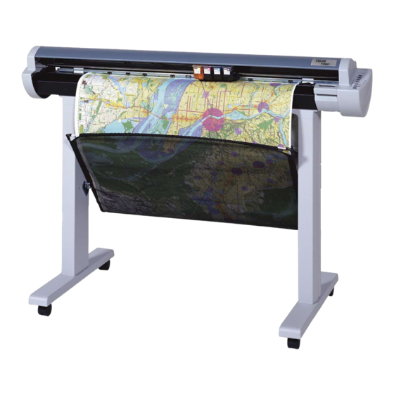
General Description Figure 1-1. T-200 and T-200+ Inkjet Printer/Plotter. Introduction This manual provides service information for the ENCAD , Inc. 36 ® inch T-200 and T-200+ Color Inkjet Printer/Plotters. It is written for service personnel who possess analog and digital circuitry experience. - Page 17 ENCAD T-200 and T-200+Service Manual media uses different maximum plotting areas than roll media. See the Printer Specifications in the User Guide for more details on the media size printable area. A Centronics parallel connection is provided to interface with the host computer.
-
Page 18: Overview
ENCAD T-200 and T-200+Service Manual Overview Printers draw according to instructions issued from a “host” computer. Every printer is engineered to understand a specific set of instructions and to execute each instruction in a precise manner. In addition, most printers are designed to execute predetermined characters automati- cally without a specific line-by-line instruction from the program. -
Page 19: Warnings, Cautions And Notes
ENCAD T-200 and T-200+Service Manual Warnings, Cautions and Notes Warnings, cautions and notes are used when additional information, instructions or care should be observed. In this manual warnings, cautions and notes precede the text to which each applies. The defini- tion of each is provided below. -
Page 20: Printer Specifications
ENCAD T-200 and T-200+Service Manual Printer Specifications The specifications and performance characteristics of the T-200 and T-200+ Color Inkjet Printers are as follows: Max Printing Area: Resolution: Norm 34.8” 600x600 dpi or 884 mm 300x600 dpi Extend 35.61” 904 mm Interface: Centronics parallel Language Emulation:... -
Page 21: Contents Of This Service Manual
ENCAD T-200 and T-200+Service Manual Environment: Storage: Operating: 40° to 95° F 65° to 85° F (5° to 35° C) (18° to 29° C) 5% to 80% RH 20% to 70% RH non-condensing non-condensing Weight: minus 14.4° F (8° C) 70 lbs(31 kg) variation from daily operating threshold... - Page 22 ENCAD T-200 and T-200+Service Manual Chapter 3 MAINTENANCE - This chapter covers the scheduled maintenance, cleaning procedures and alignment/adjustments recommended to perform on the printers. Diagnostics and a signal flow diagram are also listed. Chapter 4 TROUBLESHOOTING - A table containing problems that could occur and possible causes and repairs is found in this chapter.
-
Page 23: Technical Support
ENCAD T-200 and T-200+Service Manual Technical Support ENCAD offers full technical support and service for its various prod- ucts. If you are unable to find the answer to your question in either the User’s Guide, Service Manual, or other related publications, check out ENCAD’s Knowledge Base located on ENCAD’s website support: ENCAD Website: http://www.encad.com... -
Page 24: Chapter 2 Theory Of Operation
Theory of Operation Introduction This chapter explains the mechanical and electrical theory of operation of the ENCAD T-200 and T-200+ color inkjet printers. The T-200/T-200+ is a PowerPC 33MHz microprocessor-based digital printer that receives plotting instructions from a host computer through the Centronics parallel interface. -
Page 25: General Block Diagram
ENCAD T-200 and T-200+ Service Manual SERVO CARRIAGE AXIS DRIVE MOTOR PAPER SENSOR ENCODER SENSOR CARRIAGE DISPLAY MICRO- CIRCUITS PROCESSOR CARRIAGE ASSEMBLY GATE POWER ARRAY SUPPLY MEMORY CIRCUITS MPWA LOWER STEPPER PAPER AXIS DRIVE DRIVE MOTOR ASSEMBLY LEGEND ELECTRICAL CONNECTION MECHANICAL CONNECTION MAIN DATA BUS Figure 2-1. -
Page 26: Paper (Media) Axis Drive
ENCAD T-200 and T-200+ Service Manual Paper (Media) Axis Drive PINCH ROLLERS STEPPER MOTOR LOWER ROLLER SHAFT ASSY REDUCTION GEAR Figure 2-2. Paper (Media) Axis Drive. The Paper (Media) Axis Drive moves the plotting media in a direction perpendicular to the length of the printer. This friction drive utilizes a micro-step drive technology and consists of a stepper motor, reduction gears, lower drive shaft assembly, and pinch rollers. -
Page 27: The Carriage Axis Drive
ENCAD T-200 and T-200+ Service Manual The Carriage Axis Drive Figure 2-3. Carriage Axis Drive. The Carriage Axis Drive moves the printer’s carriage assembly along the length of the printer. The drive consists of a servo motor, linear encoder strip, drive belt, and tensioning assembly. These items are illustrated in Figure 2-3. -
Page 28: Main Printed Wiring Assembly (Mpwa)
ENCAD T-200 and T-200+ Service Manual Main Printed Wiring Assembly (MPWA) STEPPER MOTOR CARRIAGE CONTROLLER FLASH EEPROM MICRO- PROCESSOR DATA BUS SERVO MOTOR (CPU) CONTROLLER GATE DYNAMIC SERIAL ARRAY EEPROM CONTROL PANEL MEMORY CIRCUITS PARALLEL Figure 2-4. Main Printed Wiring Assembly. The Main Printed Wiring Assembly (MPWA) consists of seven func- tional areas: Microprocessor (CPU) -
Page 29: Microprocessor
ENCAD T-200 and T-200+ Service Manual Microprocessor The microprocessor (an IBM PowerPC) is the central processor unit which supervises system functions, executes the printer firmware, manipulates data, and controls input/output data busses. It has two built-in serial ports, a two channel DMA (Direct Memory Access) controller, a timer module, clock generator, and an on-board chip select generator. -
Page 30: Memory Circuits
ENCAD T-200 and T-200+ Service Manual The gate array contains the hardware logic for dot firing, monitoring changes in the Carriage Assembly position, controlling DMA through the parallel port, receiving commands from the microswitches and generating the PWM (Pulse Width Modulation) waveforms for the servo controller. -
Page 31: Dram
ENCAD T-200 and T-200+ Service Manual The system firmware is stored in Flash EEPROM. The Flash EEPROM allows the firmware to be upgraded by downloading the files containing the new firmware. It can be erased and reprogrammed more than 10,000 times. The term “Flash” means that bytes cannot be individually erased. -
Page 32: Stepper Motor Controller
ENCAD T-200 and T-200+ Service Manual Stepper Motor Controller Figure 2-6. Stepper Motor Controller. The media is driven by a Stepper Motor, which drives the media in a direction perpendicular to the width of the printer. The media in the printer can advance forward and backward, depending upon the commands which the Stepper Motor receives from the microprocessor. - Page 33 ENCAD T-200 and T-200+ Service Manual 2. Motor current sense The voltage across a series current sense resistor is measured and level shifted so that it is centered around 5V. 3. Comparator This portion divides the output of the reference waveform generator by two and compares it to the output of the motor current sensor.
-
Page 34: Servo Motor Controller
ENCAD T-200 and T-200+ Service Manual Servo Motor Controller ENCODER MOTOR SERVO SERVO DRIVER CONNECTOR MOTOR GATE ARRAY CARRIAGE CARRIAGE CONNECTOR MAIN PWA Figure 2-7. Servo Motor Controller. The Carriage Assembly is driven by the Servo Motor. The speed of the Carriage Assembly is controlled by varying the duty cycle of the signal applied to the controller. -
Page 35: Quadrature Signal Generation
ENCAD T-200 and T-200+ Service Manual Figure 2-8. Quadrature Signal Generation. The direction that the Carriage Assembly is moving is known based upon the state of one detector’s output and the direction of the transition of the other detector’s output. A hardware counter in the gate array increments as the Carriage Assembly moves left and decrements as the Carriage Assembly moves right. -
Page 36: Control Panel
ENCAD T-200 and T-200+ Service Manual Control Panel ERROR READY RESET SHORTCUT MENU MENU SELECT LOAD Figure 2-9. Control Panel. The Control Panel is located on the right side of the printer and contains two indictors ERROR READY and seven buttons RESET resets all conditions to factory select settings... -
Page 37: Interface Circuits: Serial & Parallel
ENCAD T-200 and T-200+ Service Manual SELECT when depressed, accepts the slection shown on the display UP ARROW cycles through the available options DOWN ARROW cycles through the available options LOAD loads the media Interface Circuits: Parallel MICRO- GATE PARALLEL PROCESSOR ARRAY CONNECTOR... -
Page 38: Carriage Assembly Circuits
ENCAD T-200 and T-200+ Service Manual Carriage Assembly Circuits OPTICAL ENCODER OPTICAL SENSOR TRAILING CABLE PAPER SENSOR TRAILING CARRIAGE CABLE CONNECTION FROM CARTRIDGE 1 MPWA INKJET CARTRIDGE 2 DRIVERS CARTRIDGE 3 CARTRIDGE 4 CARRIAGE ASSEMBLY Figure 2-11. Carriage Assembly Circuits. The Carriage Assembly contains: 1) Carriage PWA 2) Optical Sensors... -
Page 39: Display Assembly
ENCAD T-200 and T-200+ Service Manual The paper sensor circuitry senses for the presence of loaded media. It does this automatically during the start-up and load sequences. It also constantly monitors the media during printing to determine if the media has run out. If no paper is sensed, the paper sensor sends this information to the MPWA, which immediately begins an ‘out of paper’... -
Page 40: Power Supply
ENCAD T-200 and T-200+ Service Manual Power Supply An internal UL recognized switching power module supplies power for the printers. It provides a constant 24VDC output from input voltage in the 90-132 VAC and 180-246 VAC ranges. A power switch turns the power on and off. -
Page 41: Chapter 3 Maintenance
Maintenance Introduction This chapter contains general maintenance and cleaning instructions for the T-200 and T-200+ printer. Scheduled Maintenance Scheduled maintenance consists of a list of checks that are planned to be performed on a regular basis or when conditions warrant it. Scheduled maintenance can be thought of as preventive maintenance since its purpose is to prolong the life of the printer. -
Page 42: Cleaning Procedures
ENCAD T-200 and T-200+ Service Manual Cleaning Procedures Always turn the printer OFF, remove the power cord and the interface cable before cleaning the printer. An electri- cal shock hazard may be present if these procedures are not followed. External Cleaning CAUTION Do not use abrasive cleansers of any sort on the surfaces of the printer. -
Page 43: Service Station Cleaning
ENCAD T-200 and T-200+ Service Manual Printer problems can be caused by an accumulation of dirt or other contamination on the slide shaft. This contamination may lead to drag on the carriage. Extreme drag results in a “carriage axis failure” fault and will stop the carriage motion. -
Page 44: Linear Encoder Strip Cleaning
ENCAD T-200 and T-200+ Service Manual 4. Using a cotton swab dampened with distilled water, wipe the seals and the rubber wiper in the service station until no more ink residue or dust can be removed. 5. With a dry swab, wipe all moisture from the seals and wipers. 6. -
Page 45: Cartridge Dimples Cleaning
ENCAD T-200 and T-200+ Service Manual Figure 3-1. Encoder Strip Cleaning. Cartridge Dimples Cleaning CARTRIDGE DIMPLE AREA Figure 3-2. Cartridge Dimple Region. Maintenance... -
Page 46: Flex Cable Contact Cleaning
ENCAD T-200 and T-200+ Service Manual The cartridge dimple area can easily be contaminated by oils and dirt on fingers and hands or ink spilled onto them. This causes the cartridges to not receive some of the electrical signals for a proper firing of the jets. This can be seen as a misfiring of the cartridge. -
Page 47: Clean And Inspect Stepper Motor Gears
ENCAD T-200 and T-200+ Service Manual Cleaning the flex cable contact area is very important due to the ease of which this area can become dirty. The flex for the yellow cartridge is deceiving because it is not readily apparent that it is dirty. This also causes the cartridges to not receive all of the electrical signals for a proper firing of the jets. -
Page 48: Clean And Inspect Carriage Assembly
ENCAD T-200 and T-200+ Service Manual Clean and Inspect Carriage Assembly Foreign material on the carriage assembly could short out signals being developed on the carriage assembly and cause erroneous prints or even damage to the carriage assembly. A very common problem is where ink has been spilled onto the carriage assembly. -
Page 49: Main Pwa Connection Locations
ENCAD T-200 and T-200+ Service Manual Figure 3-4. Main PWA Connection Locations. Table 3-1. Main PWA Connections. not used Servo Motor Parallel Port not used Display Circuits Power Supply PC133 DIMM socket Stepper Motor Vacuum/Cooling Fan not used Trailing Cable Maintenance... -
Page 50: Carriage Pwa Connection Locations
ENCAD T-200 and T-200+ Service Manual Figure 3-5. Carriage PWA Connection Locations. Table 3-2. Carriage PWA Connections. Yellow Drivers Encoder Sensor Magenta Drivers Trailing Cable Cyan Drivers Paper Sensor Black Drivers Figures 3-4 & 3-5 and Tables 3-1 & 3-2 show the locations of all the connectors on the MPWA and carriage board respectively. -
Page 51: Replace Carriage Bushings
ENCAD T-200 and T-200+ Service Manual RIBBON LOCKING MECHANISM UNLOCKED LOCKED CONNECTOR ASSEMBLY Figure 3-6. Ribbon Connector Locking Mechanism. Replace Carriage Bushings The carriage bushings are rated for approximately 1500 hours of operational usage. Many factors including, but not limited to, hours/ day used, cleanliness of the slide shaft and general ambient environ- ment make it impossible to calculate the average time that the carriage bushings to last. -
Page 52: Servo Motor Winding Resistance Check
ENCAD T-200 and T-200+ Service Manual Servo Motor Winding Resistance Check Figure 3-7. Servo Motor. 1. Disconnect the servo motor connection from J7 on the MPWA. 2. Using a standard ohmmeter or multimeter, connect the meter leads to the two wires going to the motor. 3. -
Page 53: Stepper Motor Winding Resistance Check
ENCAD T-200 and T-200+ Service Manual Stepper Motor Winding Resistance Check 7.2-8.0 ohms 7.2-8.0 ohms WIRE Figure 3-8. Stepper Motor. 1. Disconnect the stepper motor connection from J10 on the MPWA. 2. Using a standard ohmmeter or multimeter, measure between pins 1 (red wire) and 3. -
Page 54: Banding: Hardware Vs Software
ENCAD T-200 and T-200+ Service Manual Banding: Hardware vs Software The technician must be able to identify whether the banding that is being observed is related to either a hardware or a software problem. The two examples in Figure 3-9 represent classic types of hardware and software banding errors. -
Page 55: Common Banding Causes
ENCAD T-200 and T-200+ Service Manual 2) Print a test file approved by ENCAD that uses only the printer driver software and the ENCAD printer. If the test file prints correctly, the problem lies in either the software package that generated the print or the RIP, if used. A simple test to determine if the banding is caused by the computer/ RIP/application or the printer is to rotate the image 90 degrees and see if the banding rotates or remains in the same orientation as the previ-... - Page 56 ENCAD T-200 and T-200+ Service Manual 6. Wiping during a print can sometimes cause a band of lighter density color in the image. Auto wipe may need to be temporarily turned off to prevent banding. 7. Operator intervention. If someone lifts up the media on the take- up side of the printer while it is printing, it can cause momentary banding in the print.
-
Page 57: Alignments/Adjustments
ENCAD T-200 and T-200+ Service Manual 14. Static electricity. Using certain types of media (i.e. polyester- based media), static electricity buildup within the media roll may effect the un-roll resistance and cause momentary banding to occur. However this has not been tested. 15. -
Page 58: Dial Gauge Micrometer Assembly
ENCAD T-200 and T-200+ Service Manual You will need the following: · Height Gauge Kit Assembly · 1/4" open and box end wrench (.110” thick) Height Gauge (Alignment) Kit Contents are: Dial Gauge Micrometer Modified Novajet Cartridge for newer products Modified Novajet 4/Pro/Pro 50 Cartridge - Not Used Platen/Carriage Shaft Mounting Block Calibration Jo Block (1.434”) -
Page 59: Measurement Positions For Slide Shaft
ENCAD T-200 and T-200+ Service Manual MEASURE MEASURE MEASURE LAST SECOND FIRST ADJUST IF NECESSARY Figure 3-11. Measurement Positions for Slide Shaft. 3. Measure the right side (next to media alignment mark.) and note the difference. Divide this amount by two. 4. -
Page 60: Head Height Alignment Procedure
ENCAD T-200 and T-200+ Service Manual For example: If the Left = 0, Right = +0.004”, then the center should be adjusted to + 0.002”. This will ensure a smooth plane of travel for the carriage assembly. There are no adjustments on either end of the shaft in all models. -
Page 61: Setting Up Tools From Height Gauge Kit
ENCAD T-200 and T-200+ Service Manual SPIN HEAD ON MICROMETER MICROMETER GAUGE DIAL GAUGE TO FACE BACKWARDS TIGHTEN SET SCREWS TEST CARTRIDGE MEASURING TIP EXTENDER ENSURE TIP EXTENDS BELOW CARTRIDGE 1/4" (6mm) Figure 3-14. Setting Up Tools from Height Gauge Kit. 3. -
Page 62: Test Cartridge Installed
ENCAD T-200 and T-200+ Service Manual 4. Remove the Cyan ink cartridge. Snap the test cartridge with the micrometer gauge into the position vacated by the Cyan ink cartridge. See Figure 3-16. Ensure that the micrometer can be read from the BACK of the printer. Figure 3-16. - Page 63 ENCAD T-200 and T-200+ Service Manual NOTE The actual measurement is different than the true head height due to the fact that the test cartridge does not con- tain a jet plate assembly. A difference had to be calcu- lated to compensate for the lack of a jet plate assembly on the test cartridge.
-
Page 64: Paper Skew Adjustment
ENCAD T-200 and T-200+ Service Manual Paper Skew Adjustment The purpose of the Paper Skew Adjustment is to make certain that the Pinch Roller in the Upper Roller Support stays centered on its shaft and/or has a gap when the Lower Roller is rotated forward for approxi- mately two full revolutions. -
Page 65: Mounting Screw Information
ENCAD T-200 and T-200+ Service Manual NOTE The rollers should be adjusted moving from the right side of the Platen to the left side of the Platen. 1. Load a sheet of B-Size paper and adjust Rollers #8, #7, and #6, following the directions in the Adjustment of Pinch Roller Supports section. -
Page 66: Pinch Roller Support And Mounting Screws
ENCAD T-200 and T-200+ Service Manual ROLLER PINCH ROLLER Y-ARM ASSEMBLY PINCH ROLLER SPACER LEFT MOUNTING RIGHT MOUNTING SCREW SCREW ORIENTATION STANDING BEHIND THE PLOTTER, FACING THE BACK OF THE PLOTTER Figure 3-18. Pinch Roller Support and Mounting Screws. 4. If the mounting screw on the right side is loosened (turned counterclockwise), the roller will move to the left. - Page 67 ENCAD T-200 and T-200+ Service Manual 6. It is extremely important that you maintain downward pressure (towards the floor) on the head of each screw at the same time as you tighten or loosen the screws. Each screw must be completely at the bottom edge of its hole in the back of the Y-Bracket.
-
Page 68: Other Functional Requirements
ENCAD T-200 and T-200+ Service Manual Other Functional Requirements The paper skew has a tendency to increase as the size of paper increases (B-Size through E-Size). When adjusting the skew, make sure that: 1. the skew for B-Size paper is as close to the low end of the range as possible;... -
Page 69: Adjustment Of Pinch Roller Supports
ENCAD T-200 and T-200+ Service Manual Adjustment of Pinch Roller Supports NOTE Be sure to perform the adjustment according to the se- quence given in Figure 3-17. Visual Verification Make sure that the roller is centered in the Y-Arm. The gap between the roller and the Y-Arm should be approximately equal on both sides of the roller. -
Page 70: Observation Of Paper Skew At Rear Media Alignment Mark
ENCAD T-200 and T-200+ Service Manual Observation of Paper Skew at Rear Media Alignment Mark 1. Position a sheet of the appropriate size paper for loading. The cut corner should be the top right corner of the paper as you load it. -
Page 71: Observation Of Paper Skew At Front Media Alignment Mark
ENCAD T-200 and T-200+ Service Manual Observation of Paper Skew at Front Media Alignment Mark 1. Press FEED MEDIA and then the UP ARROW to move the media forward while you observe the paper skew at the Front Media Alignment Mark. 2. -
Page 72: Adjustment Of The Mounting Screws
ENCAD T-200 and T-200+ Service Manual Adjustment of the Mounting Screws Figure 3-24 shows how the motion (rapid drifting to the right or to the left) of the roller determines which mounting screw should be tightened in order to eliminate the motion of the roller so that the roller stays in the center of the shaft and/or there is a gap when the Lower Roller is rotated forward. -
Page 73: Color Calibration
ENCAD T-200 and T-200+ Service Manual Color Calibration This procedure describes how to check that the cartridges are properly aligned for color plotting and should be followed each time the ink cartridges are installed. Figure 3-25 is a representation of how a color calibration looks when printed. - Page 74 ENCAD T-200 and T-200+ Service Manual The “Color Horizontal Head-to-Head Calibration” checks the alignment of the nozzles horizontally and allows corrections when required. Just enter the value below the set of lines that are correctly aligned. Be careful that you are aligning the correct color by observing the C (cyan), M (magenta), and Y (yellow) on the right side of the plot.
-
Page 75: Deadband Alignments
ENCAD T-200 and T-200+ Service Manual Deadband Alignments Deadband calibration compensates for minute differences created when bidirectional printing is used. Unidirectional printing is not affected by deadband. There are two types of deadband tests: Fast Deadband Slow Deadband Figure 3-26. Slow Deadband. Figure 3-26 shows what the display will look like when printing the slow deadband test if it is out of alignment. -
Page 76: Color Deadband Alignment
ENCAD T-200 and T-200+ Service Manual To perform the Slow Deadband Alignment Depress the “Menu” key on the control panel to begin the main menu subroutine. Using the “Up Arrow”, Down Arrow” and “Select” keys on the control panel select: Utility Menu Db Calib Slow Db Test... - Page 77 ENCAD T-200 and T-200+ Service Manual To perform the Color Deadband Alignments Depress the “Menu” key on the control panel to begin the main menu subroutine. Using the “Up Arrow”, Down Arrow” and “Select” keys on the control panel select: Utility Menu Db Calib Color Db Test...
-
Page 78: Paper Axis Test
ENCAD T-200 and T-200+ Service Manual Paper Axis Calibration The paper axis calibration procedure ensures that the processing that drives the stepper motor is correct to minimize line length accuracy errors. To perform the paper axis procedure: Depress the “Menu” key on the control panel to begin the main menu subroutine. - Page 79 ENCAD T-200 and T-200+ Service Manual 33" Figure 3-27. Paper Axis Test. With a precision drafters measuring stick, measure the exact distance from each of the “T” intersections. Select Paper Axis=XX. The XX will read “33.00” if the plotter is set in English units or “83.82”...
-
Page 80: Diagnostics Menu
ENCAD T-200 and T-200+ Service Manual Diagnostics Menu To get to the Diagnostics Menu: Depress the “Menu” key on the control panel to begin the main menu subroutine. Using the “Up Arrow”, Down Arrow” and “Select” keys on the control panel select: Utility Menu Service Menu Diag. - Page 81 ENCAD T-200 and T-200+ Service Manual Carriage Test - Prints 5 sets of 3 parallel lines to test the vibration characteristics of the carriage assembly. Color Test - The Color Test prints a wide swath of each color (total of four) to test for banding. The test is selectable in the amount of ink that is to be printed.
- Page 82 ENCAD T-200 and T-200+ Service Manual Firmware Download/Upgrading The normal method of downloading new firmware is to send the file as if it was a standard print job. To perform the firmware download, follow the steps listed below: 1. Power OFF printer, wait 15 seconds. 2.
-
Page 83: Internal Cabling And Signal Flow Diagrams
ENCAD T-200 and T-200+ Service Manual 6. Wait approximately 20 to 40 seconds later until you hear a SINGLE beep, indicating the download was successful. You may encounter a set of double beeps shortly after sending the firmware file, but you must wait until you hear the SINGLE beep. -
Page 84: Mpwa Connections Diagram
ENCAD T-200 and T-200+ Service Manual Figure 3-28. MPWA Connections Diagram. Maintenance 3-44... -
Page 85: Carriage Pwa Connections Diagram
ENCAD T-200 and T-200+ Service Manual Figure 3-29. Carriage PWA Connections Diagram. Maintenance 3-45... -
Page 86: Chapter 4 Troubleshooting
Troubleshooting Introduction Chapter 4, Troubleshooting consists of a table that is intended to aide the technician in troubleshooting the T-200 and T-200+ printers. This table addresses symptoms with their possible causes and solutions. Basic troubleshooting skills will be required to perform the symptom identification, troubleshooting, fault isolation, and repair of the printer when using this table. -
Page 87: Initialization Failure
ENCAD T-200 and T-200+ Service Manual Table 4-1. Troubleshooting Table (cont). Symptoms Possible cause Solution No Power (cont) • DC output replace power voltage not supply present (see Figure 3-28 for pin-out) • DC voltage replace MPCB present at MPCB Initialization Failure •... -
Page 88: Internal Error "Carriage Axis Failure
ENCAD T-200 and T-200+ Service Manual Table 4-1. Troubleshooting Table (cont). Symptoms Possible cause Solution Media Does Not • media control driver corrupted - Move (cont) switches are reload printer operating correctly driver • firmware reload firmware corrupted • bad MPWA replace MPWA •... - Page 89 ENCAD T-200 and T-200+ Service Manual Table 4-1. Troubleshooting Table (cont). Symptoms Possible cause Solution Internal ERROR • dirty encoder perform Encoder “Carriage Axis strip Strip Cleaning Failure” (cont) procedure • dirt under the remove carriage carriage bushings bushings and clean •...
-
Page 90: Internal Error "Encoder Sensor Failure
ENCAD T-200 and T-200+ Service Manual Table 4-1. Troubleshooting Table (cont). Symptoms Possible cause Solution Internal ERROR “Encoder Sensor Failure” • encoder sensor reseat encoder cable unseated sensor cable • bad encoder replace encoder sensor sensor Internal ERROR “Paper Sensor Failure”... -
Page 91: Internal Error "Mpcb Failure
ENCAD T-200 and T-200+ Service Manual Table 4-1. Troubleshooting Table (cont). Symptoms Possible cause Solution Internal ERROR “MPCB Failure” • bad MPWA replace MPWA Unrecognized Cartridges Error • faulty connection check cartridges of cartridge ID chip to flex cable • wrong cartridges check cartridges installed •... -
Page 92: Does Not Print
ENCAD T-200 and T-200+ Service Manual Table 4-1. Troubleshooting Table (cont). Symptoms Possible cause Solution Does Not Print • no media verify media is loaded measured properly • bad connection reseat cable between computer connections on and printer computer and printer •... - Page 93 ENCAD T-200 and T-200+ Service Manual Table 4-1. Troubleshooting Table (cont). Symptoms Possible cause Solution Ink Cartridge • flex contacts 1) perform Flex Misfiring (cont) dirty or damaged Cable Contact Cleaning procedures 2) replace carriage assembly • cartridge dimple 1) perform area dirty or Cartridge Dimple damaged...
-
Page 94: Paper Skewing
ENCAD T-200 and T-200+ Service Manual Table 4-1. Troubleshooting Table (cont). Symptoms Possible cause Solution Paper Skewing • stepper motor clean assemblies and gearing dirty or perform Inspect damaged Stepper Motor Gears procedure • lower roller torque screws down loose securing lower roller Printer Output is Banding... - Page 95 ENCAD T-200 and T-200+ Service Manual Table 4-1. Troubleshooting Table (cont). Symptoms Possible cause Solution Printer Output is • color calibration perform Color Banding (Horizontal) required Calibration (cont) • paper axis perform Paper Axis calibration Test Calibration required • carriage bushings replace bushings worn or damaged •...
-
Page 96: Printer Output Is Banding (Vertical)
ENCAD T-200 and T-200+ Service Manual Table 4-1. Troubleshooting Table (cont). Symptoms Possible cause Solution Printer Output is • corrupted clear NVRAM Banding (Horizontal) NVRAM (cont) • carriage head check carriage height incorrect head height and perform calibrations • incompatable or replace memory defective memory module... -
Page 97: Printer Output Is Banding (Horizontally And Vertically)
ENCAD T-200 and T-200+ Service Manual Table 4-1. Troubleshooting Table (cont). Symptoms Possible cause Solution Printer Output is Banding (Horizontally and Vertically) • dirty encoder clean encoder strip strip • defective encoder replace encoder strip strip • bad MPWA replace MPWA Keypad Locked- Up or Not Func- tioning Properly... -
Page 98: Noisy Operation
ENCAD T-200 and T-200+ Service Manual Table 4-1. Troubleshooting Table (cont). Symptoms Possible cause Solution Noisy Operation • ink or paper clean printer debris in printer • obstruction in remove obstruction/ path of carriage clean printer • carriage replace carriage bushings worn bushings •... -
Page 99: Line Quality Degraded
ENCAD T-200 and T-200+ Service Manual Table 4-1. Troubleshooting Table (cont). Symptoms Possible cause Solution Line Quality Degraded • ink cartridges clean and prime dirty or clogged ink cartridges • cartridge dimple clean or replace region dirty or cartridge damaged •... -
Page 100: Fan Does Not Power Up
ENCAD T-200 and T-200+ Service Manual Table 4-1. Troubleshooting Table (cont). Symptoms Possible cause Solution Line Quality • drive belt worn replace drive belt Degraded (cont) • drive belt replace frame slipping on idler tensioner, spring, or idler • vacuum fan not replace fan operating assembly... -
Page 101: Initialization Troubleshooting
CadJet T-200 Service Manual Initialization Troubleshooting The sequence that the printer follows during initialization (power up) is as follows: 1. Power supply turns on - LED D2 on carriage turns on then D5 turns on. 2. Reads the Flash ROM information. 3. -
Page 102: Carriage Board Led D2 And D5 Locations
CadJet T-200 Service Manual Turn the unit off immediately after the LED D5 returns to the dimly lit status to ensure no damage occurs to the carriage or carriage cover due to the carriage movement as stated in step 11. Snap the cover back onto the carriage. -
Page 103: Chapter 5 Assembly\Disassembly
Assembly\Disassembly Introduction Chapter 5 contains the procedures for removal and replacement of the T-200 and T-200+ printer assemblies and mechanisms. Illustrations are provided for clarity. Steps for each replacable part may depend on parts already removed in previous diassembly procedures. It is recom- mended that you read through each procedure before beginning the removal and replacement of any assemblies or mechenisms. -
Page 104: Removing The Right Cover Assembly
ENCAD T-200 and T-200+ Service Manual Always turn the printer OFF, remove the power cord and the interface cable before beginning any disassem- bly procedures. An electrical shock hazard may be present if these precautions are not followed. Removing the Right Cover Assembly Removing the Right Cover Assembly provides access to the Memory Module, MPWA, and all MPWA connectors (Stepper Motor, Servo Motor, Fan, Display, Power Supply and Trailing Cable). -
Page 105: Removal Of Right Cover Assembly
ENCAD T-200 and T-200+ Service Manual 4. Using a #2 Phillips screwdriver, loosen the top and front captive fastener screws and remove the bottom back screw on the inside of the Right Cover. The front captive fastener screw can be accessed by inserting the screwdriver into the groove on the Display Assembly as shown on the lower right side of Figure 5-1. -
Page 106: Removing The Mpwa Connectors
ENCAD T-200 and T-200+ Service Manual Removing the MPWA Connectors CAUTION Do not pull the cables from the connectors on the J3 location (Display Cable) and J6 location (Trailing Cable) ubtil they are unlocked. Doing so may cause damage to the cable. -
Page 107: Removing The Mpwa
ENCAD T-200 and T-200+ Service Manual 1. Disconnect the Display Cable connector at the J3 location. Pull forward on the connector lock and remove the flex cable from the connector. 2. Disconnect the Trailing Cable connector at the J6 location. Use the thumb and forefinger to pull forward on the connector lock and remove the Trailing Cable from the connector. -
Page 108: Removing The Right Sideplate
ENCAD T-200 and T-200+ Service Manual To remove the MPWA: 1. Put on an ESD wrist strap. 2. Use a #2 6” Phillips screwdriver to remove the three remaining screws holding the MPWA onto the side plate. See Figure 5-2 for locations. -
Page 109: Reinstalling The Right Sideplate
ENCAD T-200 and T-200+ Service Manual 4. While holding the Right Side Plate, remove the screws securing the side plate to the Platen. See Figure 5-3. 5. Slowly pull the Right Side Plate away from the Platen while feeding the cables through the side plate. Reinstalling the Right Side Plate To reinstall the Right Side Plate, reverse the steps followed when removing the Right Side Plate:... -
Page 110: Memory Module Removal
ENCAD T-200 and T-200+ Service Manual 4. Reinstall the Trailing Cable at J6. When inserting the Trailing Cable connector, apply pressure on the locking clip towards the MPWA in order to lock the connector in place. Test to make sure the connector is locked by pulling slightly on the cable to see if it comes out. -
Page 111: Memory Module Installation
ENCAD T-200 and T-200+ Service Manual Memory Module Installation The memory module is secured by locking tabs located at both of the narrow edges of the module. To install the memory module, verify that the locking tabs are in the unlocked position then align the module over the slot, ensuring that the module is oriented properly. -
Page 112: Reinstalling The Left Cover
ENCAD T-200 and T-200+ Service Manual Figure 5-4. Removal of the Left Cover. Reinstalling the Left Cover To reinstall the Left Cover, proceed as follows: 1. While holding the Left Cover, reinstall the three screws that secure the Left Cover. The four screws are reinserted as shown on Figure 5-4. -
Page 113: Removal Of The Servo Motor
ENCAD T-200 and T-200+ Service Manual 4. Remove the Right Cover, MPWA and Right Side Plate for removal of the Servo Motor. REAR SERVO MOTOR SCREW PULLEY CUT-OUT CARRIAGE BELT FRONT SCREW Figure 5-5. Removal of Servo Motor. 5. Use a #2 Phillips screwdriver to remove the back screw on the Servo Motor. -
Page 114: Reinstalling The Servo Motor
ENCAD T-200 and T-200+ Service Manual PUSH IN HERE TO SLACKEN CARRIAGE BELT Figure 5-6. Compression of Frame Tensioner. 8. Support the Servo Motor with one hand and remove the front screw. 9. Remove the ServoMotor out of the right side of the Platen. Reinstalling the Servo Motor 1. -
Page 115: Removing The Display Assembly
ENCAD T-200 and T-200+ Service Manual 7. Move the Carriage Assembly back and forth to check the Carriage Belt tension. 8. Reinstall the Trailing Cable Cover and the Top Cover. Removing the Display Assembly 1. Disconnect the power cord and the interface cables. 2. -
Page 116: Reinstalling The Display Assembly
ENCAD T-200 and T-200+ Service Manual Reinstalling the Display Assembly Reinstall Display Assembly by reversing the procedure used to remove it. When reinserting the Display Cable, make sure that the silver fingers on the end of the cable face the Display PWA. Route the Display Cable over the groove on the top of the Right Side Plate, down between the Right Side Plate and the MPWA and around to the front of the MPWA near the J3 connector. -
Page 117: Reinstalling The Service Station Assembly
ENCAD T-200 and T-200+ Service Manual 3. Reach into the Right Cover and pull back on the Service Station release tab located on the far side of the Service Station. See Figure 5-8. 4. Raise the right side of the Service Station out of the Platen. 5. -
Page 118: Electronics Cover Removal
ENCAD T-200 and T-200+ Service Manual Remove the Carriage Assembly, Carriage Belt and the Frame Tensioner 1. Remove the Top Cover and Trailing Cable Cover. 2. Remove the Left and Right Covers. Figure 5-9. Electronics Cover Removal. Assembly\Disassembly 5-16... -
Page 119: Strain Relief Removal/Installation
ENCAD T-200 and T-200+ Service Manual 3. With a flathead screwdriver, press the Electronics Cover tab located in the upper slot on the left side of the Carriage Assembly. See Figure 5-9. Lift up on the front left side of the Carriage Cover until it comes part way off of the Carriage Assembly. -
Page 120: Frame Tensioner
ENCAD T-200 and T-200+ Service Manual 8. Push the Carriage Belt through the Frame Tensioner enough to remove the Idler Pulley Assembly from the Frame Tensioner, and then set aside the Idler Pulley Assembly and the Frame Tensioner. See Figure 5-11. COMPRESSION SPRING FITS OVER THIS POST COMPRESSION SPRING FRAME TENSIONER... -
Page 121: Carriage Belt Clamp
ENCAD T-200 and T-200+ Service Manual BUMP CARRIAGE BELT RIGHT POST OF BELT CLAMP LEFT POST OF BELT CLAMP Figure 5-12. Carriage Belt Clamp. 12. Push the Carriage Belt away from the right post of the Belt Clamp and gently lift up to finish removing the Carriage Belt from the Belt Clamp. -
Page 122: Carriage Pwa Removal/Installation
ENCAD T-200 and T-200+ Service Manual Remove the Carriage PWA CAUTION Integrated circuits may become weakened or damaged by electrical discharge. Do not touch or work near integrated circuits without wearing an ESD wrist strap. 1. Perform the Carriage Assembly, Carriage Belt, and the Frame Tensioner Removal procedures to remove the Carriage Assembly from the Slide Shaft. -
Page 123: Remove The Paper Sensor Or The Encoder Sensor
ENCAD T-200 and T-200+ Service Manual 4. Unlock the latch on the right end of the Carriage Assembly and lift up the right end of the Carriage PWA. See Figure 5-13. 5. Slide the Carriage PWA to the right to remove the tab on the left end of the Carriage PWA from the slot in the Carriage Assembly. -
Page 124: Paper And Encoder Sensor Removal
ENCAD T-200 and T-200+ Service Manual TO REMOVE PAPER SENSOR BOARD, GRASP HERE AND PULL UP PUSH DOWN ON CLIP , PUSH DOWN ON ENCODER, THEN PULL OUT THIS PIECE OF PLASTIC (ONE ON EACH SIDE) MUST CLEAR THE RIDGES ON THE UNDERSIDE OF THE HOLDER Figure 5-14. -
Page 125: Install The Paper Sensor Or The Encoder Sensor
ENCAD T-200 and T-200+ Service Manual 3. To remove the Encoder Sensor: a. Unlock the connector at J2 and remove the flex cable. b. Turn the Carriage Assembly over and lay it with the top side facing down. Push down on the plastic clip and at the same time push down on the Encoder until the plastic pieces on each side of the Encoder clear the ridges which hold it in place. -
Page 126: Replacing The Carriage Bushings
ENCAD T-200 and T-200+ Service Manual Grasp the Paper Sensor between thumb and index finger and guide the sides of the board into the grooves on each side of the opening. See Figure 5-15. d. Push the Paper Sensor board down into the Carriage Assembly until it snaps firmly into place. -
Page 127: Carriage Bushing Removal
ENCAD T-200 and T-200+ Service Manual CARRIAGE BUSHING LATCH Figure 5-16. Carriage Bushing Removal. 2. Use a flat tip screwdriver to push up on the latch which holds the Carriage Bushing in place. See Figure 5-16. 3. Pull the Carriage Bushing out of the Carriage Assembly. 4. -
Page 128: Reinstalling The Carriage Assembly, Carriage Belt And The Frame Tensioner
ENCAD T-200 and T-200+ Service Manual TABS Figure 5-17. Carriage Bushing Installation. 5. Orient the new Bushing as shown in Figure 5-17 so that the metal tab on top of the Bushing goes into the Carriage Assembly first. 6. Push the Bushings in until they snap into place. 7. - Page 129 ENCAD T-200 and T-200+ Service Manual 5. Slide the Carriage Assembly onto the left end of the Slide Shaft, making sure that the Encoder Strip fits into the slot in the Slider and the Encoder on the Carriage PWA. Guide the belt while sliding the Carriage Assembly from left to right on the Slide Shaft.
-
Page 130: Removing The Trailing Cable
ENCAD T-200 and T-200+ Service Manual 15. Fit the Compression Spring over the post at the back of the Y-Arm Assembly. 16. Fit the notch in the front end of the Frame Tensioner over the notch in the front of the Y-Arm Assembly. 17. -
Page 131: Reinstalling The Trailing Cable
ENCAD T-200 and T-200+ Service Manual Reinstalling the Trailing Cable 1. Apply two new pieces of double sided tape to the Stabilizer Bracket. Ensure that the tape is in the same location as the original tape was. Do not remove the top protective cover on the tapes yet. 2. -
Page 132: Removing The Power Supply And On/Off Switch
ENCAD T-200 and T-200+ Service Manual Removing the Power Supply and ON/OFF Switch NOTE To gain access to all the screws that secure the Power Supply to the Platen the left leg must be loosened and turned or removed entirely from the Platen. To the left leg assembly first remove the media basket. -
Page 133: Revealing The Power Supply Screws
ENCAD T-200 and T-200+ Service Manual REMOVE LOOSEN Figure 5-18. Revealing the Power Supply Screws. Assembly\Disassembly 5-31... -
Page 134: Reinstalling The Power Supply And On/Off Switch
ENCAD T-200 and T-200+ Service Manual Reinstalling the Power Supply and ON/OFF Switch FOAM BLOCK STEPPER MOTOR LOWER ROLLER ASSY DRIVE SHAFT SUPPORT, DRIVE SHAFT POWER SUPPLY CABLE POWER ENTRY FAN ASSEMBLY MODULE EXHAUST ASSY, BRACKET, SNAP PLUG DRIVE SHAFT POWER POWER SUPPLY SUPPLY... - Page 135 ENCAD T-200 and T-200+ Service Manual 2. Connect the Power Cable coming from the MPWA to the connector on the Power Supply. Make sure that the ground from the Power Cable is still connected to the inside of the Platen, at the same location as the ground from the ON/OFF Switch.
-
Page 136: Stabilizer Bracket Removal
ENCAD T-200 and T-200+ Service Manual Figure 5-20. Stabilizer Bracket Removal. 5. Use a 7/64 Hex Nut Driver to remove the three screws from the back of the Y-Arm which hold the Stabilizer Bracket on the Y-Arm and remove the Stabilizer Bracket. See Figure 5-20. Reinstalling the Stabilizer Bracket and Encoder Strip The new Stabilizer Bracket will already have the new Encoder Strip as... -
Page 137: Disassembly Of Plotter Before Removing The Inner Platen Parts
ENCAD T-200 and T-200+ Service Manual in the Y-Arm and use the 7/64 Hex Nut Driver to tighten them. (The exact positioning of the screws in the slot will be done later during the Carriage Height Adjustment in Chapter 3.) 2. - Page 138 ENCAD T-200 and T-200+ Service Manual RIGHT CAUTION ROLLGUIDE DO NOT REMOVE SCREWS TO Y-ARM ASSY LEFT ROLLGUIDE SCREWS LEFT RIGHT COVER SIDE PLATE SCREWS Figure 5-21. Disassembly of Plotter Prior to Removing the Inner Platen Parts. 7. Remove the Left and Right Rollguides from the back of the Platen. 8.
-
Page 139: Removing The Inner Platen Parts
ENCAD T-200 and T-200+ Service Manual Removing the Inner Platen Parts Refer to Figure 5-20 and Figure 5-22 during this procedure. REMOVE (2) REMOVE (2) REMOVE (2) DRIVE SHAFT SUPPORT WITH STEPPER MOTOR REMOVE THROUGH RIGHT END OF PLATEN CENTER DRIVE SHAFT SUPPORT REMOVE THROUGH SNAP PLUG OPENING LEFT DRIVE SHAFT SUPPORT REMOVE THROUGH LEFT END OF PLATEN... -
Page 140: Removing The Foam Block
ENCAD T-200 and T-200+ Service Manual 6. Using a #1 6” or 8” Phillips screwdriver, remove the 4 black flat- head screws which hold the left and middle Drive Shaft Supports in place. There are two screws in the center of the Platen, and two screws approximately three inches to the left of the left brass bracket. -
Page 141: Removing The Stepper Motor
ENCAD T-200 and T-200+ Service Manual 9. Using a #1 6” or 8” Phillips screwdriver, loosen but do not remove the 2 black flat-head screws which hold the Stepper Motor Assembly. Hold the Stepper Motor Assembly with your right hand so it does not drop suddenly and use your left hand to finish unscrewing the two screws and remove them. - Page 142 ENCAD T-200 and T-200+ Service Manual PIVOT NUT SPRING OILITE PIVOT SCREW BUSHING RETAINER SPRING SCREW BOWED WASHER WASHER RETAINING RING RETAINING RING Figure 5-24. Lower Drive Assembly and Stepper Motor Assembly. 1. Once the Inner Platen Parts have been removed, remove the Stepper Motor from the Stepper Motor Bracket by unhooking the Extension Spring from the post on the Stepper Motor Bracket.
-
Page 143: Reinstalling The Stepper Motor
ENCAD T-200 and T-200+ Service Manual 5. If you are replacing the Stepper Motor Bracket, you will need to remove the Retaining Ring, Washer, and Bowed Washer which are between the end of the Lower Drive Assembly and the Stepper Motor Bracket. Reinstalling the Stepper Motor 1. - Page 144 ENCAD T-200 and T-200+ Service Manual 3. Lay the Stepper Motor Assembly on the palm of your right hand and use your fingertips to hold up the Fan Assembly as you push the Lower Drive Shaft into the Platen. While inserting, you must lift the Fan Assembly over the cap nuts on the inside of the bottom of the Platen and make sure you do not strike the Lower Rollers or the Gear on the Lower Drive Shaft against the screws, cap nuts, or...
-
Page 145: Reassembly Of Plotter After Reinstalling The Inner Platen Parts
ENCAD T-200 and T-200+ Service Manual 11. Hold the Fan in place with your left hand and insert the screws. Make sure that the screws go in straight. Using a #2 6” or 8” Phillips screwdriver, torque them to 15 in-lbs. Do not overtighten or the threads on the screw holes will strip. -
Page 146: Removing The Upper Pinch Roller Supports
ENCAD T-200 and T-200+ Service Manual 11. Route the Display Cable through the top left edge in the Right Side Plate. Bring the Display Cable down around the flat edge of the MPWA. Connect the Display Cable at the J3 connector on the MPWA. -
Page 147: Removing The Upper Pinch Roller Support
ENCAD T-200 and T-200+ Service Manual 5. Using your fingers, pull the Upper Pinch Roller Support forward. Thie will seperate it from the Pinch Roller Spacer. Move the Pinch Roller Spacer to the side. 6. Push the Upper Pinch Roller Support towards the back of the unit and turn it 90 degrees and carefully lift it away from the Y-Arm assembly. - Page 148 ENCAD T-200 and T-200+ Service Manual Installing the Upper Roller Supports Make sure that the Carriage Belt is kept looped over the front of the Slide Shaft while installing the new Upper Pinch Roller Supports, as follows: 1. Place the roller end of an Upper Pinch Roller Support behind the Slide Shaft (between the back of the Slide Shaft and the front of the Stabilizer Bracket) and push it forward as far as possible through the Upper Pinch Roller Support opening in the front of the Y-...
- Page 149 ENCAD T-200 and T-200+ Service Manual NOTE Make sure that the Carriage Belt is not twisted. One way to check this is by standing at the left end of the plotter and looking down the length of the inside of the Y-Bracket. You can also check for twisting by moving the Carriage Assembly as far as possible to the left end of the Slide Shaft.
-
Page 150: Chapter 6 Parts List
Parts List This chapter lists the items and their associated numbers for the parts and assemblies of the ENCAD T-200 and T200+ printers that are field replaceable. The list is in order of part name as identified in the assembly/disassembly chapter. This list is to be used in conjunction with the assembly/disassembly procedures to aquire the necessary parts and properly install them into the printer. - Page 151 ENCAD T-200 and T200+ Service Manual FIGURE ITEM PART NAME PART # ROLLGUIDE, RIGHT, ASSY ....206828-5 ROLLGUIDE, LEFT, ASSY ....204969-6 COVER ASSY, LEFT ....... 217512-00 POWER ENTRY ASSY ......207508 POWER SUPPLY ASSY, 150W ....218759-00 CABLE, POWER SUPPLY TO MPWA ....218762-00 HARDWARE KIT ........
-
Page 152: Left Side Parts Breakdown
ENCAD T-200 and T200+ Service Manual Figure 6-1. Left Side Parts Breakdown. Parts List... - Page 153 ENCAD T-200 and T200+ Service Manual FIGURE ITEM PART NAME PART # SPRING, COMPESSION ......209052 RETRACTING STOP, ASSEMBLY ..204246-1 COVER ASSY, TOP ......... 217860-00 BELT ............. 205678 SPRING, COMPRESSION (IDLER) ..203999 IDLER ASSEMBLY ........203405-1 FRAME, TENSIONER ......203870-1 TRAILING CABLE ASSY ......
-
Page 154: Platen And Above Parts Breakdown
ENCAD T-200 and T200+ Service Manual Figure 6-2. Platen and Above Parts Breakdown. Parts List... - Page 155 ENCAD T-200 and T200+ Service Manual FIGURE ITEM PART NAME PART # PRINT SERVER (OPTIONAL) ....218239-00 SIDE PLATE, RIGHT ......217516-00 MAIN PCB, T-200, SERVICE ....2119668-025 DRAM DIMM, 32M ........212456-00 COVER ASSEMBLY, WITH KEYPAD, RIGHT ............. 217510-00 DISPLAY, HOUSING, ASSY ....
-
Page 156: Right Side Parts Breakdown
ENCAD T-200 and T200+ Service Manual Figure 6-3. Right Side Parts Breakdown. Parts List... - Page 157 ENCAD T-200 and T200+ Service Manual FIGURE ITEM PART NAME PART # MOTOR ASSY, SERVO, W/FERRITE .......... 213674-04 BLOCK, RIGHT FOAM ......217568-00 MOTOR ASSY, STEPPER, W/FERRITE AND GEAR ...... 210848-1 BRACKET ASSY, DRIVE SHAFT, RIGHT ..........204916-1 LOWER DRIVE E, ASSY, COMPLETE WITH STEPPER MOTOR AND RIGHT BRACKET ........
-
Page 158: Inner Platen Parts Breakdown
ENCAD T-200 and T200+ Service Manual Figure 6-4. Inner Platen Parts Breakdown. Parts List... - Page 159 ENCAD T-200 and T200+ Service Manual FIGURE ITEM PART NAME PART # COVER, CARRIER ELECTRONICS ..215111-02 CARRIAGE PWA ........212151-05 ENCODER SENSOR W/FLEX ....209578-101 STRAIN RELIEF ........215659-00 PEN CARRIER, 208, PARTIAL ....210004 CARRIAGE BUSHING SET (2) ....209568 PAD, BUSHING ........
-
Page 160: Carriage Assembly Parts Breakdown
ENCAD T-200 and T200+ Service Manual Figure 6-5. Carriage Assembly Parts Breakdown. Parts List 6-11... - Page 161 ENCAD T-200 and T200+ Service Manual FIGURE ITEM PART NAME PART # SEAL, 104/208 .......... 206502 WIPER ............. 209276 SERVICE STATION, COMPLETE ASSEMBLY ..... 207611-03 Parts List 6-12...
-
Page 162: Service Station Assembly Parts Breakdown
ENCAD T-200 and T200+ Service Manual Figure 6-6. Service Station Assembly Parts Breakdown. Parts List 6-13...
Need help?
Do you have a question about the ENCAD T200+ and is the answer not in the manual?
Questions and answers