Leica LS10 User Manual
Digital level
Hide thumbs
Also See for LS10:
- Quick manual (286 pages) ,
- User manual (130 pages) ,
- Quick manual (10 pages)
Table of Contents
Advertisement
Quick Links
Advertisement
Table of Contents

Related Manuals for Leica LS10


Summary of Contents for Leica LS10
- Page 1 Leica LS10/LS15 User Manual Version 3.0 English...
- Page 2 Refer to the following resources for all LS10/LS15 documentation/software: • the Digital Levels USB documentation card • https://myworld.leica-geosystems.com Leica Geosystems On the last page of this manual, you can find the address of Leica Geosystems head- Address Book quarters. For a list of regional contacts, please visit http://leica-geosystems.com/contact-us/sales_support.
- Page 3 Add all products that you and your company own and explore your world of Leica Geosystems: View detailed information on your prod- ucts and update your products with the latest software and keep up- to-date with the latest documentation.
-
Page 4: Table Of Contents
Measurement Guidelines General Measurement Guidelines Guidelines for Special Measurement Situations Guidelines for Taking a Measurement Manual Input Screen for Optical Height Reading Settings Work Settings Regional Settings Data Settings Screen & Audio Settings Mode Settings Interface Settings LS10/LS15, Table of Contents... - Page 5 14.3 Adjusting Line-of-Sight Error 14.4 Adjusting the Optical Crosshair 14.5 Aligning the Camera Crosshair 14.6 Calibrating the Digital Compass 14.7 Adjusting the Circular Level of the Instrument 14.8 Adjusting the Electronic Level 14.9 Servicing the Tripod LS10/LS15, Table of Contents...
- Page 6 17.3.2 Dangerous Goods Regulations Software Licence Agreement Appendix A Menu Tree Appendix B Directory Structure Appendix C Corrections and Formulas Appendix D GeoCom Commands Appendix E GSI Online Commands Introduction General Commands and Descriptions Operating Commands LS10/LS15, Table of Contents...
-
Page 7: Safety Directions
Important paragraphs which must be adhered to in practice as they enable the product to be used in a technically correct and efficient manner. LS10/LS15, Safety Directions... -
Page 8: Definition Of Use
• To ensure that it is used in accordance with the instructions. • To be familiar with local regulations relating to safety and accident prevention. • To inform Leica Geosystems immediately if the product and the application becomes unsafe. • To ensure that the national laws, regulations and conditions for the operation of the product are respected. -
Page 9: Hazards Of Use
Strong magnetic fields in the immediate vicinity (e.g. transformers, melting furnaces...) may influence the compensator and compass (only LS15) of the instru- ment and lead to measuring errors. Precautions: When working near strong magnetic fields, check results for plausibility. LS10/LS15, Safety Directions... - Page 10 Product-specific treatment and waste management information can be downloaded from the Leica Geosystems home page at http://www.leica- geosystems.com/treatment or received from your Leica Geosystems dealer. Only Leica Geosystems authorised service centres are entitled to repair these prod- WARNING ucts. LS10/LS15, Safety Directions...
-
Page 11: Electromagnetic Compatibility Emc
Precautions: Although the product meets in combination with radio or digital cellular phone devices recommended by Leica Geosystems the strict regulations and standards which are in force in this respect, Leica Geosystems cannot completely exclude the possibility that other equipment may be disturbed or that humans or animals may be affected. -
Page 12: Fcc Statement, Applicable In U
• Connect the equipment into an outlet on a circuit different from that to which the receiver is connected. • Consult the dealer or an experienced radio/TV technician for help. Changes or modifications not expressly approved by Leica Geosystems for compliance WARNING could void the user's authority to operate the equipment. -
Page 13: Description Of The System
Mechanical bubble Electronic bubble / Tilt check Communication (USB host, USB device) Bluetooth RS232/USB Lemo connector interface Internal flash memory for 30.000 measurements Available - Not available LS10/LS15, Description of the System... -
Page 14: Container Contents
Spare stylus (optional) f) Allen keys (1.5 mm/2 mm) g) GEV223 USB data transfer cable (optional) h) Car adapter cable for GKL311 (optional) i) GEV192 AC power adapter for GKL311 (optional) j) Sunshade k) Rain Cover LS10/LS15, Description of the System... -
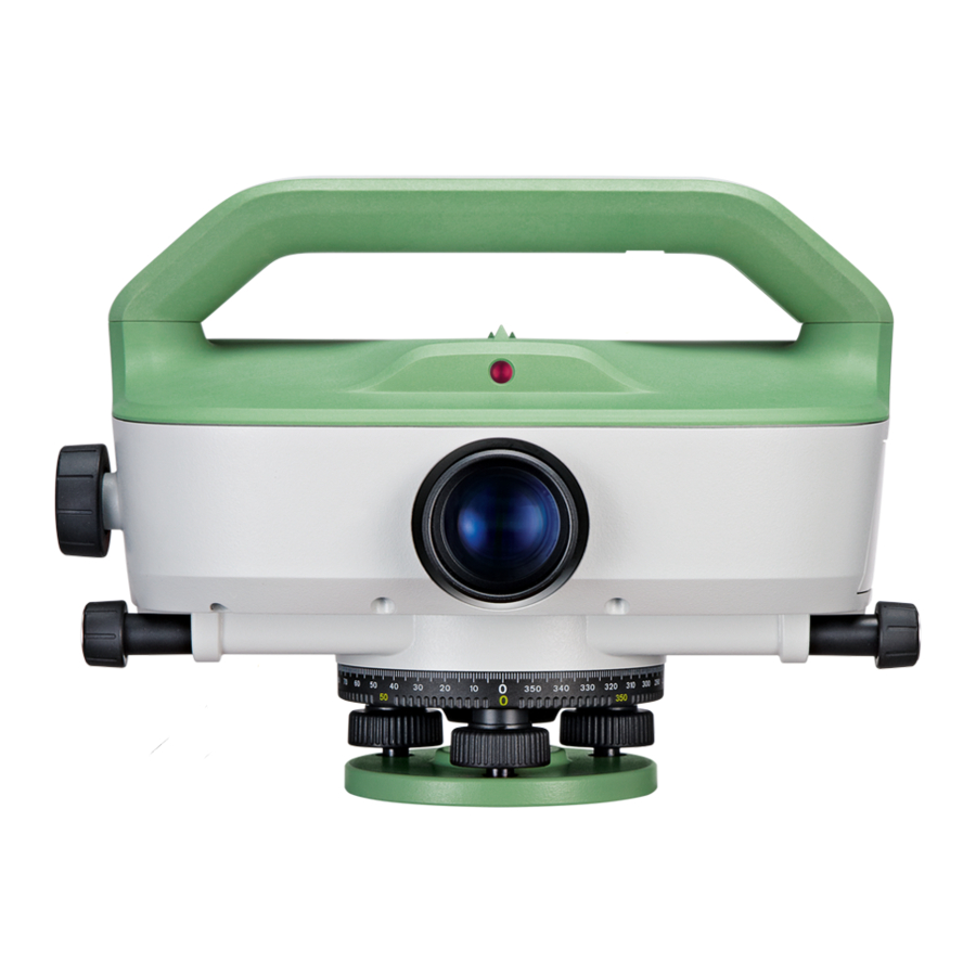
Page 15: Instrument Components
Trigger key d) Stylus for touchscreen e) RS232 serial/USB interface with external power supply (only LS15) f) Horizontal drive g) Overview camera (only LS15) h) Objective i) Horizontal circle j) Footscrews k) Base plate 010045_002 LS10/LS15, Description of the System... -
Page 16: User Interface
For details on how to define the functions of trigger key, refer to "6.1 Work Settings". Function keys that are assigned to the variable functions displayed at the bottom of the screen. LS10/LS15, User Interface... -
Page 17: Operating Principles
Deletes the character at the cursor position. Softkey Clear Deletes all characters entered into the input field. Softkey Switches between alphanumeric and numeric mode. ABC/ In edit mode the position of the decimal place cannot be changed. The decimal place is skipped. LS10/LS15, User Interface... -
Page 18: Screen
Focus in screen (active field) d) Input and output fields e) Softkeys 007928_001_en The screen is touch-sensitive and optimised for operation with the supplied stylus. Tap on an icon, field or tab to run a function. LS10/LS15, User Interface... -
Page 19: Status Icons
Instrument needs to be levelled before a measurement can be performed. Tap the icon to open the Level & Tilt Check screen. Tilt Check on LS10 Instrument is levelled. Tap the icon to open the Level screen. Instrument needs to be levelled. Tap the icon to open the Level screen. - Page 20 System Status The battery symbol indicates the level of the remaining battery capacity, 100% full shown in the example. Tap the icon to open the Info screen. The instrument is connected to an external power supply. LS10/LS15, User Interface...
-
Page 21: Softkeys
To switch to the screen for surveying intermediate points. To open the manual coordinate entry screen. To search for fixed points or measurements. Find To display the list of available points. List To display the coordinate and job details of the selected point. View LS10/LS15, User Interface... -
Page 22: Operation
+10°C to +30°C/+50°F to +86°F if possible. • It is normal for the battery to become warm during charging. Using the chargers recommended by Leica Geosystems, it is not possible to charge the battery if the temperature is too high. -
Page 23: Data Storage
TSOX_012a Careful handling of tripod. • Check all screws and bolts for correct fit. • During transport, always use the cover supplied. • Use the tripod only for surveying tasks. TSOX_012c LS10/LS15, Operation... - Page 24 To ensure a parallax free sight for optical readings of a staff, you need to adjust the reticle to the eyesight of the user. Point the telescope towards a bright background. Turn the ocular until the reticle is focussed and appears sharp and black. LS10/LS15, Operation...
-
Page 25: Startup
To activate or deactivate the Tilt Check functionality, tap on the Level & Tilt Check icon and press the softkey Page (F3). On the Check page, select On or Off and press the softkey Cont. LS10/LS15, Operation... - Page 26 For LS10: Level Up The electronic level allows you to precisely level up the instrument. with the Electronic Step Description Level Step-by-Step Turn on the instrument. Tap on the Level & Tilt Check icon. Press the Favourites key from within any program and select Level.
-
Page 27: Main Menu
To change general instrument settings such as measure- Settings ment modes and interface settings. Refer to "6 Settings". To access instrument-related tools such as check and adjust, personal startup settings, PIN code settings, licence keys, system information Tools and firmware upload. Refer to "12 Tools". LS10/LS15, Operation... -
Page 28: Measurement Guidelines
LED light may be visible, especially when measuring in low light surrounding. This LED light is used in the illumination of the compensator and has no impact on the eye safety of the user. LS10/LS15, Measurement Guidelines... -
Page 29: Guidelines For Special Measurement Situations
"4.3 Instrument Setup". Measuring through window panes Avoid measuring through window panes. Precision mode for line levelling If a line levelling job requires high accuracy, activate the precision mode. Refer to "7.4.3 Setting Tolerances". LS10/LS15, Measurement Guidelines... -
Page 30: Guidelines For Taking A Measurement
The sensitivity of the sensor ranges from the highest frequencies of visible light down to the frequency of infrared light. Electronic Height Step Description Reading with LS10 Instrument 007890_001 Set up the instrument, level it and focus the reticle. Set up staff vertically with the bar code turned toward the instrument. - Page 31 In case you cannot perform an electronic height reading, you can take an optical height reading and add it to the levelling line. For more details, refer to "5.4 Manual Input Screen for Optical Height Reading". LS10/LS15, Measurement Guidelines...
- Page 32 Angle Both the LS10 and LS15 are equipped with a rotatable horizontal circle. The angle unit Measurement with is 360° subdivided into 1° intervals. The gon division is printed in steps of 50 gon Horizontal Circle below the 360°...
-
Page 33: Manual Input Screen For Optical Height Reading
Distance Method Tape Perform an optical height reading and measure the distance with a tape. Enter the values for the staff height and for the distance. Press Cont to add the entered data to the current levelling line. LS10/LS15, Measurement Guidelines... -
Page 34: Settings
The start screen is displayed after turning on the instrument. You Instr.Start can define one of the following screens as start screen: • Home (Main Menu) • Compass Calib (only LS15) • Level Bubble • Q-Level • BasicLevel • LineLevel LS10/LS15, Settings... -
Page 35: Regional Settings
Deleting a language: If more than one language is installed, you can delete a language, as long as it is not the chosen operating language. To delete an inactive language, select the language and press Delete. LS10/LS15, Settings... - Page 36 °F Degree Fahrenheit. Tab Time The current time. Time (24h) Shows an example of the selected date format. Date Format dd.mm.yyyy, You can choose between three display formats mm.dd.yyyy for all date-related fields: day-month-year, month-day-year or year-month-day. yyyy.mm.dd LS10/LS15, Settings...
-
Page 37: Data Settings
Memory All recorded data is sent to a connected computer, Interface either through Bluetooth or serial interface. Select the respective interface in the Interface Settings screen Sets the GSI output format. GSI-Format 81..00+12345678 GSI 8 GSI 16 81..00+1234567890123456 LS10/LS15, Settings... -
Page 38: Screen & Audio Settings
You can set the volume of the beep. Normal Normal volume. Increased volume. Loud Beep is deactivated. The screensaver is activated and starts Screensaver after 1 min, after 2 min, after 5 min, after 10 min after the selected time. The screensaver is deactivated. LS10/LS15, Settings... -
Page 39: Mode Settings
20 m. Field Description The instrument carries out a single measurement (n = 1). Single Enter the number of measurements to be made (n = 2...99). Mean The instrument calculates the average of all measurements. LS10/LS15, Settings... - Page 40 Median of all measurements by using the two central values. Tracking The instrument continuously takes single measurements until you end the procedure. Press RecCont to save the last valid measurement data. Press EndTrck to stop the measure- ments without saving data. LS10/LS15, Settings...
-
Page 41: Interface Settings
The default Bluetooth PIN is ’0000’. Default To reset the fields to the default inter- face settings. Available, if RS232 is selected as instrument port. For LS10: Field Description Port : Instrument port. Communication is via the Mini-USB port. Mini USB Communication is via Bluetooth. - Page 42 Leica RS232 Default When you select Default, the communication parameters are reset to the Leica RS232 Settings default settings: • 115200 Baud, 8 Databit, No Parity, CR/LF Endmark, 1 Stopbit.
-
Page 43: Programs
The highlighted code is added to the meas- urement that is stored next. For details on adding or editing a code refer to "9 Coding". East Easting coordinate of the point. North Northing coordinate of the point. Height coordinate of the point. Height LS10/LS15, Programs... -
Page 44: Pointsearch
All points starting with "A" are found, for example, A9, A15, ABCD, A2A. All points containing only one "1" are found, for example, 1, A1, AB1. All points starting with "A" and containing only one "1" are found, for example, A1, AB1, A51. LS10/LS15, Programs... -
Page 45: Point Id & Incrementation
When measuring another special point, press the respective user key. The previously entered individual point ID is automatically entered into the Foresight Pt field and incremented. To all following points, the running point ID is applied again. Repeat the process as desired. LS10/LS15, Programs... -
Page 46: Q-Level Program
Manage Codes screen. For more details on managing codes, refer to "9 Coding". Map (only LS15) This page displays a graphical overview over the last five instrument stations and the related measurements. For more details refer to "11 MapView". LS10/LS15, Programs... -
Page 47: Measurement Procedure For Q-Level
If one or more fixpoints with this ID are already stored in the current job, all available fixpoints are displayed in the Points Found screen. Select the desired fixpoint and press Cont to return to the first backsight screen. LS10/LS15, Programs... - Page 48 Softkey To display further softkeys. SO dH To display the Set Out dH screen. SO Dist To display the Set Out Distance screen. Back To exit SetOut and return to the fore- sight/backsight display. LS10/LS15, Programs...
- Page 49 Pt ID: If desired, you can change the point ID. Default value is 1001. The point ID is incremented after each measurement. Rem.: If desired, enter a remark. When you enter a code, the field name changes to Code. SO dH: Enter the height difference that needs to be set out. LS10/LS15, Programs...
- Page 50 SO D: Enter the distance that needs to be set out. Press the trigger key to take a measurement. Display field Dist: Measured distance. Depending on the difference between entered and measured distance, the following fields and graphical elements are displayed: LS10/LS15, Programs...
- Page 51 ID during measurements" (within "7.1.3 Point ID & Incrementation"). Rem. Additional Remarks concerning the measurement (optional). Press the trigger key to measure the foresight point. The measured values are displayed in the fields Height FS, dH, Staff and Distance. LS10/LS15, Programs...
-
Page 52: Basiclevel Program
This page displays the live image of the overview camera. Use the LS15) Camera page to quickly aim at the staff. The selected levelling method is displayed in the upper right-hand corner with the current measurement step (backsight or foresight) highlighted red. LS10/LS15, Programs... -
Page 53: Linelevel Program
Manage Codes screen. For more details on managing codes, refer to "9 Coding". Map (only LS15) This page displays a graphical overview over the last five instrument stations and the related measurements. For more details refer to "11 MapView". LS10/LS15, Programs... -
Page 54: Setting A Job
Once a job is set up, all subsequent recorded data will be stored in this job. If no job is defined and you start a program, or if you record a measurement within Q-Level, the system automatically creates a new job and names it "Default". LS10/LS15, Programs... -
Page 55: Setting Tolerances
If the tolerance is exceeded, a warning message is displayed. For a detailed description of the warning message, refer to the next paragraph " Warning Message “Tolerance exceeded!”". Change to the Values screen, to enter a value for the minimum target distance. LS10/LS15, Programs... - Page 56 If the tolerance is exceeded, a warning message is displayed. For a detailed description of the warning message, refer to the next paragraph " Warning Message “Tolerance exceeded!”". LS10/LS15, Programs...
-
Page 57: Setting A Line And A Method
BF FB BF FB. • aBFFB: Backsight and foresight are measured alternatingly according to the pattern BFFB FBBF BFFB. • aFBBF: Backsight and foresight are measured alternatingly according to the pattern FBBF BFFB FBBF. LS10/LS15, Programs... -
Page 58: Measurement Procedure For Linelevel
First Foresight Screen (Station1) Total Dist: Total length of the line. Distance: Measured distance between station and staff. Dist.Balance: Distance difference ( sum B - sum F) at the current station of the line. LS10/LS15, Programs... - Page 59 Station: To show the result screen of the previous station. Check: To check the height of the last measured point with the height of a known point (fixpoint). Close: To start the calculation of the line end. LS10/LS15, Programs...
- Page 60 Line Info Screen Line ID: Line ID. No. Station: Number of stations. Total dH: Total height difference. Total Dist: Accumulated distances. Dist Balance: Distance difference ( sum B - sum F) at the current station of the line. LS10/LS15, Programs...
- Page 61 x x x x x x aBFFB B B F B B F x x x B B F B B F aFBBF x x x LS10/LS15, Programs...
-
Page 62: Lineadjust Program
These parameters are used to calculate the closure tolerance according to the described formulas. Select the type of points that you want to adjust: Adjust Pts • All Points • Line+Interm. • Line+SetOut • Line only LS10/LS15, Programs... - Page 63 • by Station: the misclosure is distributed according to the number of stations of the level line and is thus independent of the distances between the staffs. To adjust and record all points of the selected type of points, press Run. LS10/LS15, Programs...
- Page 64 To exit the screen and end the program, press OK. The original measurements are kept in the job and are stored as measured triplets. For each adjusted point, an adjusted triplet is created additionally and stored to the current job. LS10/LS15, Programs...
-
Page 65: Favourites
In addition to the Favourites key, you can use the User Key 1 and User Key 2 to quickly access functions from any measurement screen. For details on how to assign functions to the User keys, refer to "6.1 Work Settings". LS10/LS15, Favourites... -
Page 66: Coding
Codes from the Manage Menu. Access from within a program • Open the Q-Level or the LineLevel program. • Within the program, press Page to change to the page Code. • Press Edit to open the Manage Codes screen. LS10/LS15, Coding... - Page 67 Free Code List of existing code names. Use the navigation keys to toggle through the list. Additional remarks. Desc. Info 1 to More information lines, freely editable. Used to describe attributes of the code. Info 8 LS10/LS15, Coding...
-
Page 68: Free Coding
Manage from the Main Menu. Select Meas.Data to display the Manage Measurements screen. Select the job containing the free codes and press the softkey View (F4) Toggle through the list of data blocks until a free code block is displayed. LS10/LS15, Free Coding... - Page 69 To toggle between the pages of the data block (General, Code 1, Code 2). Find To display the Manage Measurements screen and select a different job. Example of a GSI-8 output: 410001+PARK AV. 42..+PARTLY CLOUDY 43..+MEAS.DONE BY LK 44..+00000000 45..+00000000 46..+00000000 47..+00000000 48..+00000000 49..+00000000 014617_001 LS10/LS15, Free Coding...
-
Page 70: Mapview
Position of the instrument station. The ID of a station is displayed in red. Position of the foresight or backsight staff. The ID of the measured points is displayed in black. Intermediate point / Set-out point. The ID of such a point is displayed in blue. Measured line to the staff. LS10/LS15, MapView... - Page 71 You can also use the navigation keys. Moving the map is useful when you have zoomed in on a view, and want to move the view around to see other areas of interest. LS10/LS15, MapView...
-
Page 72: Tools
Refer to "14.5 Aligning the Camera Crosshair". Only for LS15: F3 Digital Compass To calibrate the digital compass. Refer to "14.6 Calibrating the Digital Compass". F4 Level Bubble To adjust the electronic level of the instrument. Refer to "14.8 Adjusting the Electronic Level". LS10/LS15, Tools... -
Page 73: System Information
Build number of the current firmware version Build Number Active Language Currently activated user interface language Language Version Version of the currently used language file. Firmware version and language version should always be identical. Oper.System Operating System installed on the instrument LS10/LS15, Tools... -
Page 74: Licence Keys
Insert the USB memory stick into the USB interface within the battery compartment. Select Tools from the Main Menu. Select Licence from the Tools Menu. An information message is displayed. To confirm, press Cont. The licence key is loaded automatically on the instrument. LS10/LS15, Tools... -
Page 75: Instrument Protection With Pin
Tools from the Main Menu. Select PIN from the Tools Menu. Enter the current PIN in PIN-Code:. Press Cont. Deactivate PIN protection by setting Use PIN-Code: Off. Accept with Cont. The instrument is now no longer protected against unauthorised use. LS10/LS15, Tools... -
Page 76: Loading Software
Yes or No for each language file. At least one language must be set to Yes. To start loading the files, press Cont. Once the files are successfully loaded, the system shuts down and restarts again automatically. LS10/LS15, Tools... -
Page 77: Compass
For this purpose, you can define the compass calibration screen as start screen. Refer to "6.1 Work Settings". Access Select Tools from the Main Menu. Select Compass from the Tools Menu. LS10/LS15, Tools... -
Page 78: Data Management
To view, delete, or rename exported data files. To view the contents of a data files stored in the internal memory Viewer or on the USB memory stick. USB-Stick To view, delete, rename and create folders and files stored on the USB memory stick. LS10/LS15, Data Management... -
Page 79: Exporting Data
To Internal Memory, USB Stick or Interface: Measurements, Fixpoints, Meas.& Fixpoints Only to USB Stick: Code, Format, Backup Select whether to export all job-related data or a single job data file. Displays the selected job. Select Job LS10/LS15, Data Management... - Page 80 During the data export in XML data format or other format files, the instrument has to search the whole memory until the required data is found. Therefore, the data transfer time varies between formats. The GSI data format has the best transfer speed-performance. LS10/LS15, Data Management...
-
Page 81: Importing Data
A ’+’, ’-’, ’.’ or alphanumerical characters should not be used as delimiter values in ASCII files. These characters can also be part of the point ID or coordinate values and if so, will generate errors where they occur in the ASCII file. LS10/LS15, Data Management... - Page 82 Take note of the warning message displayed and press Cont to proceed and import the folder. If the file is an ASCII file, the Define ASCII Import screen is displayed. Define the delimiter value, the units and the data fields of the file and press Cont to continue. LS10/LS15, Data Management...
-
Page 83: Working With A Usb Memory Stick
Whilst other USB memory sticks may be used, Leica Geosystems recommends Leica industrial grade USB memory sticks and cannot be held responsible for data loss or any other error that may occur when using a non-Leica USB memory stick. ... - Page 84 • Select CopyAll to copy all screenshots in the folder to the USB memory stick. Any existing screenshots on the USB memory stick with identical file names are overwritten by the files from the internal memory. LS10/LS15, Data Management...
-
Page 85: Working With Bluetooth
LEV. To transfer the level data to Infinity, use a USB cable connection or export the files to a USB memory stick. In Leica Infinity, level data can be combined and adjusted together with total station- and GPS data sets. -
Page 86: Check & Adjust
14.1 Overview Description Leica Geosystems instruments are manufactured, assembled and adjusted to the best possible quality. Quick temperature changes, shock or stress can cause deviations and decrease the instrument accuracy. It is therefore recommended to check and adjust the instrument from time to time. This check and adjust can be done in the field by running through specific measurement procedures. -
Page 87: Adjusting Line-Of-Sight Error
To aim at the staff, you can use the overview camera within the tab Camera. • Aim at staff A and carry out a measurement (A1). • Aim at staff B and carry out a measurement (B1). • Store the measurements for station 1. LS10/LS15, Check & Adjust... - Page 88 • The distance a between the staffs should be approximately 30 m. Second position (station 2): • Position the instrument close to staff B (inside or outside). • The distance b has to be at least 2.5 m. LS10/LS15, Check & Adjust...
- Page 89 0.2 x D < Dist_B2 < 0.4 x D and D = Dist_A1 + Dist_B1. • The following requirement must be fulfilled: 0.2 x D < Dist_A1 < 0.4 x D and D = Dist_A1 + Dist_B1. Näbauer Procedure 009366_001 LS10/LS15, Check & Adjust...
-
Page 90: Adjusting The Optical Crosshair
Using an allen key, turn the adjustment screw to move the optical crosshair until the 010757_001 optical height reading corre- sponds with the Reticle value on the screen. Gently remove the allen key and put the protective cap back in place. LS10/LS15, Check & Adjust... -
Page 91: Aligning The Camera Crosshair
Press Cont to accept the new position of the camera crosshair and to close the Check & Adjust screen. Press Reset to reset the crosshair to the factory default and to return to the Check & Adjust screen. LS10/LS15, Check & Adjust... -
Page 92: Calibrating The Digital Compass
Completed 360° rounds displays the number of already completed rounds. To complete the compass calibration, press Cont (F4). An information message is displayed to inform you whether the compass cali- bration has been successful. To confirm the information message, press Cont (F4). LS10/LS15, Check & Adjust... -
Page 93: Adjusting The Circular Level Of The Instrument
Turn the horizontal circle of the instrument to 200 gon/180 deg. Avoid any vibrations while turning the instrument. Press the trigger key and wait until the message “Level Bubble calibrated!“ is displayed. Press the softkey Cont (F4) to return to the Main Menu. LS10/LS15, Check & Adjust... -
Page 94: Servicing The Tripod
Tighten the leg cap screws moderately, with the supplied allen key. Tighten the articulated joints on the tripod head enough to keep the tripod legs open when lifting the tripod off the ground. Tighten the allen screws of the tripod legs. LS10/LS15, Check & Adjust... -
Page 95: Mysecurity
Description mySecurity is a cloud-based theft protection. A locking mechanism ensures that the instrument is disabled and can no longer be used. A Leica Geosystems service centre will inform local authorities if such an instrument turns up. mySecurity is activated in myWorld. - Page 96 A warning comes up to confirm device as stolen. Click OK. The Status of the instrument changes to Stolen!. A Leica Geosystems service centre informs local authorities if such an instru- ment turns up. Locate stolen If a reported, stolen instrument is registered to myWorld, then the IP address of the instrument computer is logged.
-
Page 97: Care And Transport
Shipping When transporting the product by rail, air or sea, always use the complete original Leica Geosystems packaging, container and cardboard box, or its equivalent, to protect against shock and vibration. Shipping, transport When transporting or shipping batteries, the person responsible for the product must... -
Page 98: Cleaning And Drying
Dry the product, the transport container, the foam inserts and the accessories at a temperature not greater than 40°C /104°F and clean them. Open and dry the battery compartment. Do not repack until everything is completely dry. Always close the trans- port container when using in the field. LS10/LS15, Care and Transport... -
Page 99: Technical Data
Internal Battery GEB331 Type: Li-Ion Voltage 11.1 V Capacity: 2.8 Ah Operating time: 10-12 h Data Storage Type Capacity / Number of measurements Format Internal memory 30’000 measurements Database USB Stick 1 GB, up to 32 GB supported ASCII LS10/LS15, Technical Data... - Page 100 Magnetically damped pendulum compensator with electronic range control. LS10, LS15 Slope angle ±9’ Standard deviation 0.3 Circular Level Sensitivity: 8’/2 mm Electronic Level Working range: LS10 0.166 gon/0.150° LS15 0.110 gon/0.099° (Longitudinal, Transversal) 0.166 gon/0.150°, if Tilt Check is Off. Accuracy: LS10, LS15 0.015 gon/0.013° Autofocus Working range: 1.8 m to infinity...
-
Page 101: Measurements
3 m to 4 m 1.8 m - 110.0 m 3 m invar staff 1.8 m - 60.0 m 2.7 m 1.8 m - 100.0 m 1.82 m / 2 m 1.8 m - 60.0 m Measurement Time Typically 2.5 seconds. LS10/LS15, Technical Data... -
Page 102: Conformity To National Regulations
Leica Geosystems has developed Guidelines on “How to carry Leica products” and “How to ship Leica products” with Lithium batteries. Before any transpor- tation of a Leica product, we ask you to consult these guidelines on our web page (http://www.leica-geosystems.com/dgr) to ensure that you are in accord- ance with the IATA Dangerous Goods Regulations and that the Leica products can be transported correctly. -
Page 103: Software Licence Agreement
Leica Geosystems. Such software is protected by copyright and other laws and its use is defined and regulated by the Leica Geosystems Software Licence Agreement, which covers aspects such as, but not limited to, Scope of the Licence, Warranty, Intellectual Property Rights, Limitation of Liability, Exclusion of other Assurances, Governing Law and Place of Jurisdiction. -
Page 104: Appendix A Menu Tree
System: Instr. Type, Serial No., Equip.No.,Instr.Temp., Collim.Err., Battery, Ext.Power Softw.: Instr.-Firmware, Build Number, Active Language, Language Version, Oper.System Memory: Job, Stations, Fixpoints, Meas.Records, Occ.Job Mem., Occ.Sys.Mem. Dates: Maint.-End Date, mySec.Renewal Date, Next Service Date |—— Licence |—— PIN Use PIN-Code, New PIN-Code LS10/LS15, Menu Tree... - Page 105 |—— Load FW F1 Firmware, F2 Language(s) only |—— Compass LS10/LS15, Menu Tree...
-
Page 106: Appendix B Directory Structure
• Codelists (*.cls) |—— FORMATS • Format files (*.frt) |—— JOBS • GSI, ASCII and LandXML files (*.*) • Logfiles created from programs |—— SYSTEM • Firmware files (LS_Levels.fw) • Language files (LS_Levels_Language_xx.fw) • Licence file (*.key) LS10/LS15, Directory Structure... -
Page 107: Appendix C Corrections And Formulas
: Difference between new and current line-of- sight error. : Staff heights. : Distances of the respective staff heights. Mean S Outlier Test Maximum residual observation is discarded. Distance Balances Total Distance Station Differences : backsight distance : foresight distance LS10/LS15, Corrections and Formulas... -
Page 108: Appendix D Geocom Commands
The following table contains LS specific commands and general TPS commands of importance for the LS digital level, as well as typical return codes for these commands. For further details on GeoCOM refer to the GeoCOM manual available for Leica Total- Stations. - Page 109 Coarse correlation error. Too much coverage or insufficient code length. 12036 Fine correlation error. Too much coverage or insufficient code length. 12037 Distance outside the permitted range. 12038 Staff inverted or inverse mode activated. 12039 Bad focusing. LS10/LS15, GeoCom Commands...
-
Page 110: Appendix Egsi Online Commands Introduction
Introduction Return Codes LS10/LS15 support the GSI Online protocol known from Leica DNA and TotalStations hardware. The protocol consists of a command and reply structure as listed in the following table. All replies are in the currently configured instrument unit. -
Page 111: Operating Commands
8 = 38,400 Baud 9 = 57,600 Baud 10 = 115,200 Baud Parity 0 = None SET/71/1 1 = Odd Setting Interfacing Parity to 2 = Even Terminator 0 = CR SET/73/1 1 = CR/LF Setting Terminator to CR/LF LS10/LS15, GSI Online Commands... - Page 112 50 = 50% contrast 100= 100% contrast Unit (Length) CONF/41 0041/0000 0 = Meter 0041/0001 1 = US ft, decimal 0041/0002 2 = International ft, decimal Unit (Tempera- CONF/42 0042/0000 0 = °C ture) 0042/0001 1 = °F LS10/LS15, GSI Online Commands...
- Page 113 Earth Curvature CONF/125 0125/0000 0 = Off Correction 0125/0001 1 = On Staff Mode CONF/127 0127/0000 0 = Upright 0127/0001 1 = Inverted Output GSI CONF/137 0137/0000 0 = GSI-8 Format Length 0137/0001 1 = GSI-16 LS10/LS15, GSI Online Commands...
- Page 114 Staff Height GET/n/WI330 Command: GET/M/WI330 Reading Response:330.26+00014876 Instrument GET/n/WI95 Command: GET/M/WI95 Temperature Response: 95...6+00260000 Serial Number GET/n/WI12 Command: GET/M/WI12 Response: 12..+00348004 Instrument Name 13 GET/n/WI13 Command: GET/M/WI13 Response: 13..+0000LS15 Date: d/m/y GET/n/WI17 Command: GET/M/WI17 Response: 17..+27042015 LS10/LS15, GSI Online Commands...
- Page 115 • The staff could be out of the telescope field of view. • The instrument may not be properly focused onto the staff. Action: Check and focus onto the staff with optimum lighting. Ensure that the staff is set up in its correct position. LS10/LS15, GSI Online Commands...
- Page 116 837282-3.0.0en Original text Published in Switzerland © 2017 Leica Geosystems AG, Heerbrugg, Switzerland Leica Geosystems AG Heinrich-Wild-Strasse CH-9435 Heerbrugg Switzerland Phone +41 71 727 31 31 www.leica-geosystems.com...
Need help?
Do you have a question about the LS10 and is the answer not in the manual?
Questions and answers