Leica LS10 User Manual
Hide thumbs
Also See for LS10:
- User manual (116 pages) ,
- Quick manual (286 pages) ,
- Quick manual (10 pages)
Table of Contents
Advertisement
Advertisement
Table of Contents

Related Manuals for Leica LS10


Summary of Contents for Leica LS10
- Page 1 Leica LS10/LS15 User Manual Version 5.0 English...
- Page 2 Bluetooth SIG, Inc. All other trademarks are the property of their respective owners. Validity of this This manual applies to the LS10/LS15 Digital Levels. Where there are differ- manual ences between the instruments they are clearly described.
- Page 3 Leica Geosystems On the last page of this manual, you can find the address of Leica Geosystems address book headquarters. For a list of regional contacts, please visit http://leica-geosystems.com/contact-us/sales_support. myWorld@Leica Geosystems (https://myworld.leica-geosystems.com) offers a wide range of services, information and training material.
-
Page 4: Table Of Contents
Table of Contents Safety Directions General Definition of Use Limits of Use Responsibilities Hazards of Use Electromagnetic Compatibility (EMC) FCC Statement, Applicable in U.S. Description of the System System Components Container Contents Instrument Components User Interface Keyboard Operating Principles Screen Status Icons Softkeys Operation... - Page 5 13.2 Exporting Data 13.3 Importing Data 13.4 Working with a USB Memory Stick 13.5 Working with Bluetooth 13.6 Working with Leica Infinity Check & Adjust 14.1 Overview 14.2 Preparation 14.3 Adjusting Line of Sight Error 14.4 Adjusting the Optical Crosshairs 14.5...
- Page 6 Appendix B Directory Structure Appendix C Corrections and Formulas Appendix D GeoCom Commands Appendix E GSI Online Commands Introduction General Commands and Descriptions Operating Commands Table of Contents...
-
Page 7: Safety Directions
Safety Directions General Description The following directions enable the person responsible for the product, and the person who actually uses the equipment, to anticipate and avoid opera- tional hazards. The person responsible for the product must ensure that all users understand these directions and adhere to them. -
Page 8: Definition Of Use
Responsibilities Manufacturer of the Leica Geosystems AG, CH-9435 Heerbrugg, hereinafter referred to as Leica product Geosystems, is responsible for supplying the product, including the User Manual and original accessories, in a safe condition. Safety Directions... -
Page 9: Hazards Of Use
To be familiar with local regulations relating to safety and accident pre- • vention To inform Leica Geosystems immediately if the product and the applica- • tion become unsafe To ensure that the national laws, regulations and conditions for the oper- •... - Page 10 WARNING Distraction/loss of attention During dynamic applications, for example stakeout procedures, there is a danger of accidents occurring if the user does not pay attention to the envir- onmental conditions around, for example obstacles, excavations or traffic. Precautions: ▶ The person responsible for the product must make all users fully aware of the existing dangers.
- Page 11 WARNING Inappropriate mechanical influences to batteries During the transport, shipping or disposal of batteries it is possible for inap- propriate mechanical influences to constitute a fire hazard. Precautions: ▶ Before shipping the product or disposing it, discharge the batteries by the product until they are flat.
-
Page 12: Electromagnetic Compatibility (Emc)
Risk of injuries to users and equipment destruction due to lack of repair knowledge. Precautions: ▶ Only authorised Leica Geosystems Service Centres are entitled to repair these products. Electromagnetic Compatibility (EMC) Description The term Electromagnetic Compatibility is taken to mean the capability of the... - Page 13 Although the product meets the strict regulations and standards which are in force in this respect, Leica Geosystems cannot completely exclude the possib- ility that function of the product may be disturbed in such an electromagnetic environment.
-
Page 14: Fcc Statement, Applicable In U
Precautions: ▶ Although the product meets the strict regulations and standards which are in force in this respect, Leica Geosystems cannot completely exclude the possibility that other equipment can be disturbed or that humans or animals can be affected. ▶... - Page 15 Labelling LS10/LS15 Contains transmitter module: FCC-ID T7V1316 / IC: 216Q-1316 This device complies with part 15 of the FCC Rules. Operation is subject to the following two conditions: (1) This device may not cause harmful interference, and (2) This device must accept any interference received, including interference that may cause undesired operation.
-
Page 16: Description Of The System
Description of the System System Components Main components Component Description LS10/LS15 instrument An instrument for measuring, calculating and capturing data. Ideally suited for measure- ment tasks such as single height measure- ments, line levelling jobs, adjustment of point heights or staking out heights. -
Page 17: Container Contents
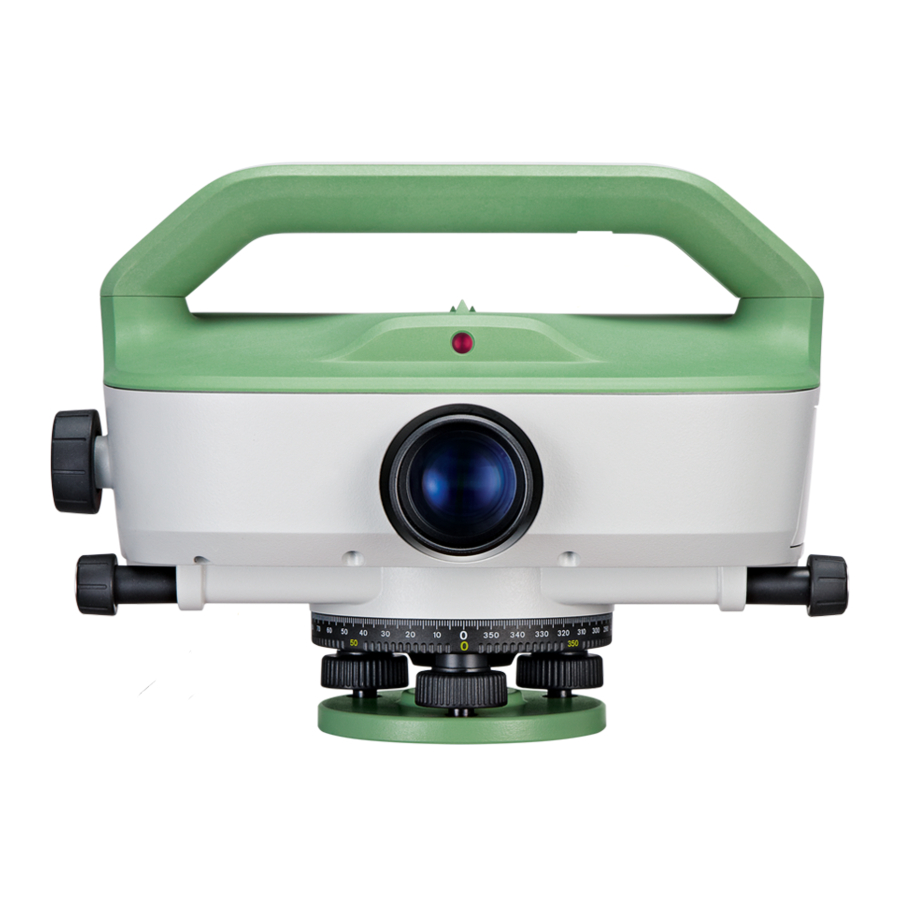
Container Contents Container contents 010043_001 Instrument Quick Guide/USB documentation card GKL311 battery charger (optional) GEB331 batteries (optional) Spare stylus (optional) Allen keys (1.5 mm/2 mm) GEV223 USB data transfer cable (optional) Car adapter cable for GKL311 (optional) GEV192 AC power adapter for GKL311 (optional) Sunshade Rain Cover Instrument Components... - Page 18 Instrument Optical sight components Focussing drive (part 2) Trigger key Stylus for touch screen RS232 serial/USB interface with external power supply (only LS15) Horizontal drive Overview camera (only LS15) Objective Horizontal circle 010045_002 Footscrews Base plate Description of the System...
-
Page 19: User Interface
User Interface Keyboard Keyboard Touch screen ON/OFF key Alphanumeric keypad Function keys F1 to F4 Home key Page key User key 1 Navigation keys Enter key e f g User key 2 010046_002 ESC key Favourites key Keys Description ON/OFF key to switch the instrument on or off or to set it into standby mode. -
Page 20: Operating Principles
Description Function keys that are assigned to the variable functions displayed at the bottom of the screen. Operating Principles Edit Fields with Use the alphanumeric keypad to enter characters directly into editable fields. Alphanumeric Keypad Numeric fields: Can only contain numerical values. Press a key of the •... -
Page 21: Screen
Description Switches between alphanumeric and numeric Softkey ABC/ mode. ☞ In edit mode the position of the decimal place cannot be changed. The decimal place is skipped. Special characters Character Description Used as wildcard in search fields for point IDs or codes. Refer to 7.1.2 Point Search. - Page 22 Instrument needs to be levelled before a measurement can be performed. Tap the icon to open the Level & Tilt Check screen. Tilt Check on LS10 Instrument is levelled. Tap the icon to open the Level screen. Instrument needs to be levelled. Tap the icon to open the Level screen.
-
Page 23: Softkeys
Icon Description The orientation of the staff is set to upright. It is only pos- sible to take measurements with the 0-mark at the bottom of the staff. Tap the icon to change the orientation to inverse. The earth curvature correction is set to On. Refer to Regional Settings for details on how to set the earth curvature correction to Off. - Page 24 more specialised softkeys are described where they appear in the program chapters. Common softkey Description functions Cont If entry screen: Confirms measured or entered values and continues the process. If message screen: Confirms message and continues with selected action or returns to the previous screen to reselect an option.
-
Page 25: Operation
It is normal for the battery to become warm during charging. Using the • chargers recommended by Leica Geosystems, it is not possible to charge the battery if the temperature is too high. Operation / discharging The batteries can be operated from -30°C to +60°C/-22°F to +140°F. -
Page 26: Data Storage
Close the battery compartment. Data Storage Description The instrument is equipped with an internal memory. In the internal memory, all data is stored within jobs in the database. From the database, you can transfer or export the data and convert it into a readable format (e.g. ASCII, HexML, GSI) by using the transfer functionality. - Page 27 Setup step-by-step Setting up the instrument on the tripod Set up the tripod. Extend the tripod legs to allow for a comfortable working posture. Fasten the instrument onto the tri- pod. Tighten the central fixing screw. 010756_001 Centring the circular level manually The circular level helps you to to coarsely level the instrument.
-
Page 28: Startup
Turn the ocular until the reticle is focussed and appears sharp and black. Startup Turn Instrument To turn the instrument on, press the ON/OFF key for 2 seconds. On/Off or Enable To turn off the instrument or set it into standby mode, press the ON/OFF key Standby Mode and select the appropriate option from the information screen. -
Page 29: Main Menu
Level & Tilt Check icon and press the softkey Page (F3). On the Check page, select On or Off and press the softkey Cont. For LS10: The digital level bubble allows you to precisely level the instrument. Precise levelling with Centre the bubble of the circular level as described in 4.3 Instru-... - Page 30 Main Menu Description of the Main Menu functions Function Description Q-Level (Quick Level): a line levelling program to start right away. Each time you access Q-Level, a new Line is started and ended when you exit the application. Q-Level ☞ You cannot adjust lines that are measured with the Q-Level application.
-
Page 31: Measurement Guidelines
Measurement Guidelines General Measurement Guidelines General Guidelines Selecting a levelling staff The measuring accuracy depends on the levelling staff that is used in combin- ation with the instrument. Use standard levelling staffs for medium range of accuracy and (calibrated) Invar levelling staffs (for example GPCL3) for highest precision. -
Page 32: Guidelines For Special Measurement Situations
Taking a precision measurement Limit the target distance to ≤ 30 m. • Ensure a minimum ground clearance of 0.5 m to minimise the influence of • refractions due to ground proximity. Apply double observation methods, such as BFFB or aBFFB, to increase the •... - Page 33 Measuring at the upper end of the levelling staff When measuring at the upper end of the levelling staff, use levelling staffs with the following lengths: 4.05 m • 2.95 m • 2.70 m • 1.95 m • 1.82 m •...
-
Page 34: Guidelines For Taking A Measurement
Guidelines for Taking a Measurement Measurement values H = 0.0000 m 007895_001 Station Levelling staff 1 (backsight staff) Levelling staff 2 (foresight staff) Levelling staff C and C for intermediate or set-out sight Staff height backsight. For double observations: B1, B2 Staff height foresight. - Page 35 Digital height reading with LS10 instrument 007890_001 Set up the instrument, level it and focus the reticle. Set up levelling staff vertically with the bar code turned toward the instrument. Coarsely aim at staff. Focus with focussing drive. Fine aim with horizontal drive.
- Page 36 Leica Infinity, these coordinates can be used to visualise the position of a levelling line. Angle measurement Both the LS10 and LS15 are equipped with a rotatable horizontal circle. The with horizontal circle angle unit is 360° subdivided into 1° intervals. The graduation in gon is printed in steps of 50 gon below the graduation in degrees.
-
Page 37: Manual Input Screen For Optical Height Reading
Turn horizontal circle to “0”. Align instrument to point B. Aim on the centre of the staff. Read the horizontal angle from the horizontal circle. In this example the horizontal angle is 60°. Manual Input Screen for Optical Height Reading Access The Manual Input screen can only be accessed from within a level- ☞... -
Page 38: Settings
Settings Work Settings Access Select Settings from the Main Menu. Select Work from the Settings Menu. Work Settings Field Description USER Key 1 You can assign one of the following functions to USER Key 2 both keys: Level: Displays the Level screen. •... -
Page 39: Regional Settings
Field Description Trigger Key You can assign one of the following functions to the trigger key: Dist: The staff is read and the distance is meas- • ured. Dist+Rec: Staff reading and distance measure- • ment will additionally be stored. AF+Dist (only LS15): Automatic focusing plus •... - Page 40 China mainland, Hong Kong and Taiwan. For instruments purchased outside this area, please contact your local Leica Geosystems representative in case the Chinese language is needed on the instrument. Deleting a language: If more than one language is installed, you can delete a lan- guage, as long as it is not the chosen operating language.
-
Page 41: Data Settings
Field Description Azimuth Sets the units displayed for all angular fields. You can Unit choose between gon and dec. deg. E,N Decimal Sets the number of decimal places displayed for all East and North coordinates and for all input/output fields. Displays East and North with no decimals. -
Page 42: Screen & Audio Settings
Field Description Sort Order Descending The selected Sort Type is ordered descend- ingly. Ascending The selected Sort Type is ordered ascend- ingly. Code Defines whether the code block is saved before or after the Record measurement. Refer to Coding. Code Defines whether the code is used for one or for many meas- urements. -
Page 43: Mode Settings
Field Description Auto-Off Enable The instrument switches off after 20 minutes without any activity. Disable The automatic switch-off function is deactiv- ated. ☞ Battery discharges quicker. Standby The instrument switches to standby mode after 5 minutes without any activity. Beep The beep is an acoustic signal and is used in the following three variations: Single beep: sounds as input confirmation after a key... - Page 44 Mode Settings Mode To select a mode setting. n Meas. Only available for Mean or Median. To set a number of measure- ments. n Min. Only available for Mean S. To set a minimum number of measurements. n Max. Only available for Mean S. To set a maximum number of measurements.
-
Page 45: Interface Settings
The default Bluetooth PIN is ’0000’. Default To reset the fields to the default interface settings. Available, if RS232 is selected as instrument port. For LS10: Field Description Port : Instrument port. Mini USB Communication is via the mini USB port. - Page 46 Leica RS232 Default When you select Default, the communication parameters are reset to the Settings Leica RS232 default settings: 115200 Baud, 8 Databit, No Parity, CR/LF Endmark, 1 Stopbit. • Settings...
- Page 47 Pin assignments (only LS15) PIN_001 Signal Function Direction Name USB_D+ USB data line In or out USB_D- USB data line In or out Signal ground RS232, receive data RS232, transmit data Identification pin In or out Power input, nominal +12 V (11 V - 16 V) Not connected Settings...
-
Page 48: Programs
Programs General 7.1.1 Common Fields Description of fields The following table describes common fields that are found within the pro- grams. Field Description PtID Point ID of the point. Backsight Pt / Point ID of backsight point. PtBS Foresight Pt Point ID of foresight point. -
Page 49: Point Id & Incrementation
It is possible to limit the point search to a particular job or to search the whole storage. The search procedure always finds fixpoints before measured points that fulfil the same search criteria. If several points meet the search criteria, then the results are ordered according to the entry date. - Page 50 PtID: Enter a point ID with 16 characters maximum. The point ID can consist of numeric and alphanumeric characters. If the point ID ends with an alphanu- meric character, the suffix “01” is added automatically after returning to one of the levelling applications. Incr: Enter an increment of maximum 9999.
-
Page 51: Q-Level Program
Q-Level Program 7.2.1 General Description The Q-Level program allows you to carry out a basic line levelling task using the BF method. Each time you access Q-Level, a new Line is started and ended when you exit the application. Use this program, if you immediately want to start measuring after switching on and setting up the instrument. -
Page 52: Measurement Procedure For Q-Level
Page Description Code This page contains a list of codes. Highlight a code to add it to the next measurement. Press Edit to edit the selected code in the Manage Codes screen. For more details on managing codes, refer to Coding. - Page 53 After storing of the measurement of the first backsight, the foresight screen is displayed. Before measuring a foresight, you can measure intermediate points or set out heights, height differences and distances. ☞ You can define an individual point ID for the next point measured.
- Page 54 Back To exit INT to BS and return to the foresight/backsight display. (ESC) To delete the last measurements taken. A confirmation message is displayed before deletion. Before taking a measurement: Pt ID Int You can enter the point ID of the intermediate point.
- Page 55 Set out heights step- ☞ Before you set out height values, ensure that these heights are by-step stored as fixpoints in the current job. To load a fixpoint, enter the ID of the point in the field Find and press the ENTER key. Select the desired fixpoint from the list and press Cont.
- Page 56 Enter the necessary data. Pt ID: If desired, you can change the point ID. Default value is 1001. The point ID is incremented after each measurement. Rem.: If desired, enter a remark. When you enter a code, the field name changes to Code. SO dH: Enter the height difference that needs to be set out.
- Page 57 Display field Dist: Measured distance. Depending on the difference between entered and measured dis- tance, the following fields and graphical elements are displayed: OUT :: Difference from entered distance (positive value). The dis- tance between instrument and levelling staff is too small. IN :: Difference from entered distance (negative value).
-
Page 58: Basiclevel Program
An information message is displayed when you exit the Q-Level program without measuring a foresight in this setup. The information message guides you to measure the required foresight so that the station storage can be com- pleted. Example: The “line” measured contains one station with a single back- sight and several intermediates or set out points. -
Page 59: Linelevel Program
Page Description Camera This page displays the live image of the overview camera. (only LS15) Use the Camera page to quickly aim at the staff. The selected levelling method is displayed in the upper right- hand corner with the current measurement step (backsight or foresight) highlighted in red. -
Page 60: Setting A Job
Page Description Camera This page displays the live image of the overview camera. (only LS15) Use the Camera page to quickly aim at the staff. The selected levelling method is displayed in the upper right- hand corner with the current measurement step (backsight or foresight) highlighted in red. -
Page 61: Setting Tolerances
Select Job Delete To delete an existing job. To create a job. Field Description Name of an existing job. Operator Name of operator (optional). Remark 1, Additional remarks (optional). Remark 2 Date Date on which the selected job was created. Time Time at which the selected job was created. - Page 62 Reset To reset tolerances to default val- ues. Field Description Precise : When taking measurements near the edge of the levelling staff, the reduced number of code elements may slightly lower the measuring accuracy. If Precise : is activated, the instrument monitors whether the height reading is within 0.50 m to either end of the staff (top and bottom).
- Page 63 Field Description Dist B-F : Only available for double observation levelling methods such as BFFB. If activated, the instrument monitors the distance balance between foresight and backsight on the current sta- tion. If the tolerance is exceeded, a warning message is dis- played.
-
Page 64: Setting A Line And A Method
Warning message Example of warning message “Tolerance screen. The title of the screen exceeded!” describes which type of tolerance has been exceeded, e.g. the dis- tance tolerance. Option Description If you select F1 Remeasure last station (1), the instru- ment assumes that all setup points of the levelling staff are still clearly identified and unchanged. -
Page 65: Measurement Procedure For Linelevel
Field Description Method Select a levelling method: BF: Backsight and foresight are measured according to • the pattern BF BF. BFFB: Backsight and foresight are measured according • to the pattern BFFB BFFB. BBFF: Backsight and foresight are measured according •... - Page 66 First Backsight Screen (Station1) Backsight/Foresight: The selected levelling method. The current view- ing direction is highlighted in red. Stat.ID: ID of the current station. PtID: ID of the start point. Rem/Free Code: If desired, you can enter an additional remark to be stored with the measurement.
- Page 67 First Backsight Screen (Station2) The field Stat.ID displays the ID of the next station. In the Backsight/ Foresight field, the first viewing direction of the next station is highlighted in red. Total dH: Height difference between start and current back- sight.
- Page 68 Check Screen Last Point: Point ID of the last measured point. Height LastPt: Height of the last measured point. Fix Point: Point ID of the selected fixpoint. Height Fix Pt: Height of the selec- ted fixpoint. Difference: Height difference between measured point and fix- point.
-
Page 69: Lineadjust Program
If the misclosure is out of tolerance, an information message is dis- ☞ played. To return to the Closure Screen, press the softkey Abort. To ignore the message and continue storing the data, press the softkey Cont. Availability of the The following table describes the availability of the softkeys SetOut and INT Softkeys SetOut and within the LineLevel application, depending on the selected levelling method. -
Page 70: Line Adjustment Step-By-Step
7.5.2 Line Adjustment Step-by-Step Define parameters for To reset the default parameters for adjustment procedure Method, a, b, and Adjust Pts, press Default. To continue with the adjustment procedure, press Cont. Select a job that contains level lines. Line Select a level line in the current job. You can only adjust lines that are recorded with the LineLevel program. - Page 71 H1, H2 Displays the height of the selected point. If you change the point ID, the height stored for this point ID is displayed. For points of the type “measured“, you can change the height. Either enter the height directly or press List to select a point with the desired height from the list of available points.
- Page 72 H(new) Displays the adjusted height of the selected point. H(old) Displays the originally measured height of the selected point. Residue Displays the height difference (residual) between the ori- ginal and the adjusted height of the selected point. To exit the screen and end the program, press OK. The original measurements are kept in the job and are stored as ☞...
-
Page 73: Favourites
Favourites Description Favourites can be accessed by pressing the Favourites key from any measurement screen. The Favourites key opens the Favourites Menu and a function can be selec- ted and activated. Favourites Favourite Description Work Returns to the Main Menu. Home Opens the Level &... - Page 74 Favourite Description Opens the Free Code screen from within a levelling application. Refer to 10 Free Coding. Free code Setting Opens the screen to change the mode set- tings. Refer to 6.5 Mode Settings. Mode To activate/deactivate the touch screen. Touch Opens the Work Settings screen.
-
Page 75: Coding
Coding Description Codes contain supplementary information about recorded points and are stored as code blocks together with the measurements. Both, coding with and without a codelist is supported. With the help of coding, points can be assigned to a particular group of information to simplify later processing. - Page 76 Manage Codes To create a code. Edit To edit the selected code. Delete To delete the selected code. Field Description Find Enter a code name to search for existing codes. If the entry does not match any existing code name, a warning message is displayed and a wildcard is automatically inserted into the field.
-
Page 77: Free Coding
Free Coding Free code function In addition to recording codes for measured points, it is possible to store mul- tiple free codes within a job. Such free codes are not related to a specific point measurement. Use the Free code function e.g. to enter additional information on the cur- rent job or line. - Page 78 Select Meas.Data to display the Manage Measurements screen. Select the job containing the free codes and press the softkey View (F4) Toggle through the list of data blocks until a free code block is dis- played. Example of a Free code data block: Page To toggle between the pages of the data block (General, Code 1,...
-
Page 79: Mapview
MapView 11.1 Overview Availability The MapView functionality is only available on the LS15 instrument. Description MapView is an interactive display feature embedded in the firmware. MapView provides a graphical display of the current and the last four instrument sta- tions. In MapView, all line measurements and intermediate sights are drawn according to their orientation in order to give you a better understanding of how the different measurement data are related to each other. - Page 80 Symbol Description Position of the levelling staff (foresight or backsight). The ID of the measured points is displayed in black. Intermediate point / Set-out point. The ID of such a point is displayed in blue. Measurement in the line, to a turning point Measurement to an intermediate or set-out point Current viewing direction of the instrument.
-
Page 81: Tools
Tools 12.1 Adjust Description The Check & Adjust Menu contains tools to be used for adjusting the line of sight, for the alignment of the camera crosshairs and for calibrating the com- pass of the instrument. Using these tools helps to maintain the measuring accuracy of the instrument. - Page 82 Reset To reset all settings to the system default. Options To display hardware-related options which this particular instrument provides. Field Description Instr. Type Displays the instrument type. Serial No. Displays the serial number of the instrument. Equip.No. Displays the equipment number. Instr.Temp.
-
Page 83: Licence Keys
example measured points, or codes within a job, and the memory space occu- pied. ☞ Before pressing Format, to format the internal memory, ensure that all important data is first transferred to a computer. Jobs, formats, codel- ists, configuration files, uploaded languages and firmware are deleted by formatting. -
Page 84: Loading Software
Enter a personal PIN in the New PIN field. The PIN must have exactly five digits. Accept with Cont. ☞ Now the instrument is protected against unauthorised use. After switching on the instrument, a PIN entry is necessary. Lock instrument step- If PIN protection is activated, it is possible to lock the instrument from within by-step any program without switching off the instrument. -
Page 85: Compass
Copy the firmware and language file into the system directory (e.g. D:\system\) on the USB memory stick. Loading a firmware file always requires to load a language file simul- ☞ taneously. Before you start the process, ensure that the system dir- ectory of the USB memory stick contains the firmware file and at least one language file. - Page 86 Access Select Tools from the Main Menu. Select Compass from the Tools Menu. Tools...
-
Page 87: Data Management
Data Management 13.1 Manage Access Select Manage from the Main Menu. Manage The Manage Menu contains all functions for entering, editing, checking and deleting data in the field. Menu item Description To select, view, create and delete jobs. Jobs are a summary of different types of data, for example, fixpoints, measure- ments or codes. -
Page 88: Exporting Data
Menu item Description Viewer To view the contents of a data file stored in the internal memory or on the USB memory stick. USB stick To view, delete, rename and create folders and files stored on the USB memory stick. 13.2 Exporting Data Description... - Page 89 Field Description Destination of the exported data: Internal Memory • USB Stick • Interface (RS232, Bluetooth) • Data Type Data type to be transferred: To Internal Memory, USB Stick or Interface: Measure- ments, Fixpoints, Meas.& Fixpoints Only to USB Stick: Code, Format, Backup Select whether to export all job-related data or a single job data file.
- Page 90 Define the delimiter value, the units and the data fields of the file and press Cont. GSI: Leica Geo Serial Interface. Fixed format. Select between GSI 8 and GSI 16. Refer to Exportable job data formats for an explanation of the formats.
-
Page 91: Importing Data
PtID East North Height Code Info1-8 POINT023 -6.2819 -179.8903 -0.3782 MAIN_ROAD 13.3 Importing Data Description Data can be imported to the internal memory of the instrument via a USB memory stick. Importable data When importing data, the instrument automatically stores the file in a direct- formats ory folder based on the file extension. - Page 92 Import data step-by- Choose the desired settings in the Import screen: step From: USB stick or Internal Memory File: Import a single file or a backup folder. Press Cont in the Import screen to proceed to the USB memory stick file directory. Select the file or backup folder on the USB memory stick to be imported and press Cont.
- Page 93 If you attach new points to the current job and a point with the same point ID already exists, the following information message is displayed: OvWrite To overwrite the point with the currently displayed point ID. Press (F4) and AlwOver to overwrite all duplicate point IDs with the new points.
-
Page 94: Working With A Usb Memory Stick
Whilst other USB memory sticks may be used, Leica Geosystems recommends Leica industrial grade USB memory sticks and cannot be held responsible for data loss or any other error that may occur when using a non-Leica USB memory stick. Keep the USB memory stick dry. -
Page 95: Working With Bluetooth
13.5 Working with Bluetooth Description The LS10/LS15 can communicate with external devices via a Bluetooth connec- tion. The Bluetooth of the instrument is a slave module only. The Bluetooth of Data Management... -
Page 96: Working With Leica Infinity
HeXML, GSI and LEV. To transfer the level data to Infinity, use a USB cable con- nection or export the files to a USB memory stick. In Leica Infinity, level data can be combined and adjusted together with data from total stations and GNSS. -
Page 97: Check & Adjust
14.1 Overview Description Leica Geosystems instruments are manufactured, assembled and adjusted to the best possible quality. Quick temperature changes, shock or stress can cause deviations and decrease the instrument accuracy. It is therefore recom- mended to check and adjust the instrument from time to time. This check and adjust can be done in the field by running through specific measurement pro- cedures. -
Page 98: Adjusting Line Of Sight Error
Before starting to work, the instrument has to become acclimatised to the ☞ ambient temperature. Take at least 15 minutes into account or approximately 2 minutes per °C of temperature difference from storage to working environ- ment. 14.3 Adjusting Line of Sight Error Line of sight error The line of sight error (collimation error) is the vertical angle (α) between the actual line of sight and the truly horizontal line of sight. - Page 99 ☞ To aim at the levelling staff, you can use the overview camera within the tab Camera. Aim at staff A and carry out a measurement (A1). • Aim at staff B and carry out a measurement (B1). • Store the measurements for station 1. •...
- Page 100 Adjustment method “From the Centre” procedure “A x Bx” 009364_001 First position (station 1): Set up the instrument centrally between staff A and B. • The centre has to be within an accuracy of ±1 m. • The distance a between the levelling staffs should approximately be 30 m. •...
-
Page 101: Adjusting The Optical Crosshairs
Förstner procedure Dist_A1 Dist_B1 Dist_B2 009363_001 009362_001 First position (station 1): Second position (station 2): Set up the instrument at 1/3 of Set up the instrument at 2/3 of • • the distance d between staff A the distance d between staff A and B. -
Page 102: Aligning The Camera Crosshairs
Take an optical height reading and check if this value corres- ponds to the Reticle value in the Result screen. If not, you need to adjust the optical crosshairs. The crosshair adjustment screw is underneath the eyepiece and is covered by a protective cap. Pull out the cap about 1 cm and slightly push it sidewards. -
Page 103: Calibrating The Digital Compass
14.6 Calibrating the Digital Compass Only for LS15 - For correct measurement results, it is recommended to perform a ☞ step-by-step compass calibration every time you set up the instrument. For this purpose, you can set the compass calibration screen as the start screen. -
Page 104: Adjusting The Digital Bubble
Turn the instrument by 180°/200 gon and observe the bubble of the circular level. If the bubble is still centred no adjustment is needed. If the bubble is not centred, correct half of the deviation by moving the adjustment screws with the supplied Allen key. 010754_001 Turn the instrument again by 180°/200 gon and observe the bubble. - Page 105 The following table explains the most common settings. The connections between metal and timber components must ☞ always be firm and tight. Tighten the leg cap screws moderately, with the supplied Allen key. Tighten the articulated joints on the tripod head enough to keep the tripod legs open when lifting the tripod off the ground.
-
Page 106: Mysecurity
Description mySecurity is a cloud-based theft protection. A locking mechanism ensures that the instrument is disabled and can no longer be used. A Leica Geosys- tems service centre will inform local authorities if such an instrument turns up. mySecurity is activated in myWorld. - Page 107 A warning comes up to confirm device as stolen. Click OK. The Status of the instrument changes to Stolen!. A Leica Geosystems service centre informs local authorities if such an instrument turns up. Locate a stolen If a reported, stolen instrument is registered to myWorld, then the IP address instrument of the computer is logged.
-
Page 108: Care And Transport
Shipping When transporting the product by rail, air or sea, always use the complete ori- ginal Leica Geosystems packaging, container and cardboard box, or its equival- ent, to protect against shock and vibration. Shipping, transport of When transporting or shipping batteries, the person responsible for the... -
Page 109: Cleaning And Drying
Charger and docking Keep chargers and docking stations away from excessive dirt, dust and • station contaminants. After unpacking the product visually inspect the charger for possible dam- • age. Unplug the product from the outlet before attempting any maintenance or •... -
Page 110: Technical Data
Instrument dimensions 276 mm 222 mm 010755_001 Weight Instrument type Weight (including GEB331 battery) LS10 3.7 kg/8.2 lbs LS15 3.9 kg/8.6 lbs Power supply External power supply using the serial interface Type Description Voltage Nominal voltage 12.8 V DC Range 10.5 V - 18 V... - Page 111 1 GB, up to 32 GB supported ASCII Environmental Temperature specifications Type Operating temperature Storage temperature [°C] [°C] LS10/LS15 −20 to +50 −40 to +70 GEB331 −30 to +60 −40 to +70 Protection against water, dust and sand Type Protection LS10/LS15...
- Page 112 LS10 0.166 gon/0.150° range LS15 0.110 gon/0.099° (Longitudinal, 0.166 gon/0.150°, if Tilt Check is Off. Transversal) Accuracy LS10, LS15 0.015 gon/0.013° Autofocus (only LS15) Type Description Working range 1.8 m to infinity Time to focus typically 4 s Digital compass...
-
Page 113: Measurements
Hereby, Leica Geosystems AG declares that the radio equipment type • LS10/LS15 is in compliance with Directive 2014/53/EU and other applic- able European Directives. The full text of the EU declaration of conformity is available at the fol- lowing Internet address: http://www.leica-geosystems.com/ce. -
Page 114: Dangerous Goods Regulations
Leica Geosystems has developed Guidelines on “How to carry Leica ☞ products” and “How to ship Leica products” with Lithium batteries. Before any transportation of a Leica product, we ask you to consult these guidelines on our web page (http://www.leica-geosystems.com/dgr) to ensure that you are in accordance with the IATA Dangerous Goods Regulations and that the Leica products can be transported correctly. -
Page 115: Software Licence Agreement/Warranty
Rights, Limitation of Liability, Exclusion of other Assurances, Governing Law and Place of Jurisdiction. Please make sure, that at any time you fully comply with the terms and conditions of the Leica Geosystems Software Licence Agreement. Such agreement is provided together with all products and can also be referred to and downloaded at the Leica Geosystems home page at http://leica-geosystems.com/about-us/compliance-standards/legal-documents... - Page 116 Appendix A Menu Tree Depending on local firmware versions the menu items may differ. ☞ Menu tree |--|Q-Level |--|Programs |--|--|BasicLevel |--|--|LineLevel |--|--|LineAdjust |--|Manage |--|--|Job |--|--|Fixpoints |--|--|Meas.Data |--|--|Codes |--|--|Formats |--|--|Del.Data |--|--|Int.Mem. |--|--|Viewer |--|--|USB stick |--|Transfer |--|--|Export |--|--|Import |--|--|Copy Lines |--|Settings |--|--|Work |--|--|--|USER Key 1, USER Key 2, Trigger key, Instr.Start, Crosshair C.
- Page 117 |--|Tools |--|--|Adjust |--|--|--|Line Of Sight, Camera Crosshair, Digital Compass, Level Bubble |--|--|Info |--|--|System: |--|--|--|Instr. Type, Serial No., Equip.No.,Instr.Temp., Collim.Err., Battery, Ext.Power |--|--|Softw.: |--|--|--|Instr.-Firmware, Build Number, Active Language, Language Ver- sion, Oper.System |--|--|Memory: |--|--|--|Job, Stations, Fixpoints, Meas.Records, Occ.Job Mem., Occ.Sys.Mem. |--|--|Dates: |--|--|--|Maint.-End Date, mySec.Renewal Date, Next Service Date |--|--|Licence |--|--|PIN...
- Page 118 Appendix B Directory Structure Description On the USB memory stick, files are stored in certain directories. The following diagram is the default directory structure. Directory structure |--|BACKUP Backup files • A backup folder is only created once a backup has been exported. |--|CODES Codelists (*.cls) •...
- Page 119 Appendix C Corrections and Formulas Formulas Earth curvature correction x: Measured Distance R: 6’378’000 m (earth radius) Line of sight error a: Difference between new and cur- rent line of sight error. : Staff readings : Distances to the level- ling staffs Mean S outlier test Maximum residual observation is discarded.
- Page 120 The following table contains LS specific commands and general TPS commands of importance for the LS digital level, as well as typical return codes for these commands. For further details on GeoCOM refer to the GeoCOM manual available for Leica TotalStations. Name...
- Page 121 Name ASCII command Reply Date is in hexadecimal format BMM_BeepAlarm %R1Q,11004: %R1P,0,0:0 DNA_GetMeasResult %R1Q,29005:7000 %R1P, 0,0:0,0.6549364292072 82,2.877974290086675, 91,53,5312137,0.01392 0634920635,20,1 7000 is waittime in ms to make the measure- ment, in reply the first argument is the height reading, the second argument is the distance DNA_SetRodPos %R1Q,29010:1 %R1P,0,0:0...
- Page 122 Code Description 12035 Coarse correlation error. Too much coverage or insufficient code length. 12036 Fine correlation error. Too much coverage or insufficient code length. 12037 Distance outside the permitted range. 12038 Staff inverted or inverse mode activated. 12039 Bad focusing. GeoCom Commands...
- Page 123 Introduction Return Codes LS10/LS15 support the GSI Online protocol known from Leica DNA and Total- Stations hardware. The protocol consists of a command and reply structure as listed in the following table. All replies are in the currently configured instru- ment unit.
- Page 124 Function Spec Setting Example Unit (Length) 0 = Meter SET/41/1 1 = US ft, decimal Setting Dis- 2 = International ft, tance(length) Unit to decimal US ft, decimal Unit (Temperature) 0 = °C (Degree SET/42/0 Celsius) Setting Temperature 1 = °F (Degree Unit to °C (Degree Fahrenheit) Celsius)
- Page 125 1 = After measure- ing after the meas- ment urement CONF commands Syntax Response Example CONF/<conf spec> 00<conf spec>/00 READING BEEP SETTING <CR/LF> <parameter> ON LS10/15: Command: CONF/30 Response: 0030/0002 Function Spec Command Response Parameters Beep CONF/30 0030/0000 0 = OFF 0030/0001...
- Page 126 Function Spec Command Response Parameters Delay CONF/78 (0...50) Range from 0 to 50: (between Increment 0 = No delay 2 strings of 10ms/ 25 = 25 ms delay sent) unit 50 = 50 ms delay Battery Level CONF/90 0090/00nn n: (0...10) 0: Empty 10: Full Instrument...
- Page 127 GET commands Syntax Example GET/n/WI/<get Single command spec> <CR/LF> where Read Distance value: n = M / I / C Command: GET/M/WI32 Response: 32…0+00040663 Combined commands Read PtID, Distance & Height reading: Command: GET/M/WI11/WI32/WI330 Response: 11..+00BM2002 32..00+00015256 330.26+00014875 Function Spec Command Example PtID...
- Page 128 Function Spec Command Example Instrument Name GET/n/WI13 Command: GET/M/ WI13 Response: 13..+0000LS15 Date: d/m/y GET/n/WI17 Command: GET/M/ WI17 Response: 17..+27042015 Date and time: GET/n/WI19 Command: GET/M/ d/m/y/min WI19 Response: 19..+04271212 Version GET/n/WI599 Command: GET/M/ WI599 Response: 599..6+00342673 Warnings and errors Message Description Possible Cause / Action...
- Page 130 837282-5.0.0en Original text (837282-5.0.0en) Published in Switzerland © 2020 Leica Geosystems AG, Heerbrugg, Switzerland Leica Geosystems AG Heinrich-Wild-Strasse CH-9435 Heerbrugg Switzerland Phone +41 71 727 31 31 www.leica-geosystems.com...
Need help?
Do you have a question about the LS10 and is the answer not in the manual?
Questions and answers