Xerox Phaser 3320 Service Manual
Hide thumbs
Also See for Phaser 3320:
- Specifications (4 pages) ,
- Installation manual (2 pages) ,
- Service manual (67 pages)
Table of Contents
Advertisement
Quick Links
Download this manual
See also:
Installation Manual
Advertisement
Table of Contents
Troubleshooting

Related Manuals for Xerox Phaser 3320


Summary of Contents for Xerox Phaser 3320
-
Page 1: Service Manual
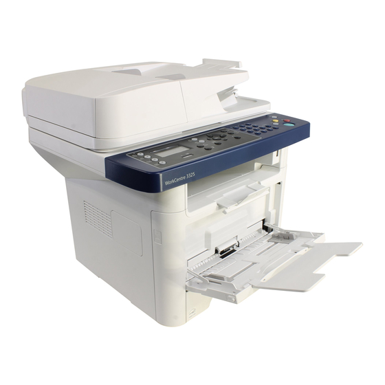
Phaser ® 3320 and WorkCentre ® 3315/3325 Service Manual Product Photo Phaser 3320 and ® WorkCentre 3315/3325 ® Service Manual Xerox Internal-Use Only... - Page 2 The following servicing instructions are for use by qualified service personnel only. To avoid personal injury, do not perform any servicing other than that contained in the operating instructions, unless you are qualified to do so. First Printing: June 2012 Xerox Internal Use Only...
- Page 3 Xerox technical training materials and service manuals are intended for use by authorized Xerox service technicians and service partners only and are not for resale. These materials may not be distributed, copied, or otherwise reproduced without prior written consent from Xerox Corporation.
-
Page 4: Table Of Contents
Phaser 3320 Rear and Side Views........ - Page 5 Phaser 3320 Service Mode Menu Map ........
- Page 6 Phaser 3320 Covers ........
- Page 7 Control Panel Board (Phaser 3320) ........
- Page 8 Optional Tray Feeder Board ............4-142 Xerox Internal Use Only Phaser 3320 and WorkCentre 3315/3325 Service Manual...
- Page 9 Parts List 2.1 Phaser 3320 Control Panel ........
- Page 10 Phaser 3320 Sensors and Wireless Board ..........7-23 Phaser 3320 Control Panel and Optional Tray Feeder Board ......7-24 WorkCentre 3315 Wiring Diagrams.
-
Page 11: General Information
• Configurations • Parts of the Printer • Control Panel • Media Path • Feeder • Print Process • Drive • Electrical • Maintenance Items • Consumables • Specifications Xerox Internal Use Only Phaser 3320 and WorkCentre 3315/3325 Service Manual... -
Page 12: About This Service Manual
General Information About this Service Manual The Phaser 3320 and WorkCentre 3315/3325 Service Manual is the primary document used for repairing, maintaining, and troubleshooting the printer. Use this manual as your primary resource for understanding the operational characteristics of the printer and all available options. This manual describes specifications and the diagnosis and repair of problems occurring in the printer and attached options. -
Page 13: Manual Organization
General Information Manual Organization The Phaser 3320 and WorkCentre 3315/3325 Service Manual contains these sections: Introductory, Safety, and Regulatory Information This chapter contains important safety information and regulatory requirements. Chapter 1 - General Information This chapter describes the printer’s operation, configuration, specifications, and consumables. -
Page 14: Safety
Wearing a wrist strap will also prevent accumulation of additional bodily static charges. Be sure to remove the wrist strap before applying power to the unit under test to avoid potential shock. Phaser 3320 and WorkCentre 3315/3325 Xerox Internal Use Only Service Manual... -
Page 15: Service Safety Summary
Read and obey all posted warning labels. Throughout the printer, warning labels are displayed on potentially dangerous components. As you service the printer, check to make certain that all warning labels remain in place. Xerox Internal Use Only Phaser 3320 and WorkCentre 3315/3325 Service Manual... -
Page 16: Servicing Electrical Components
This printer uses heat to fuse the image to the media. During operating, the Fuser is very hot. Allow the Fuser to cool before you attempt to service the Fuser or adjacent components. Phaser 3320 and WorkCentre 3315/3325 Xerox Internal Use Only... -
Page 17: Health And Safety Incident Reporting
This section defines requirements for notification of health and safety incidents involving Xerox products (equipment and materials) at customer locations worldwide. These requirements apply to Xerox Corporation and its subsidiaries worldwide. Objective To enable prompt resolution of health and safety incidents involving Xerox products and to ensure Xerox regulatory compliance. Definitions Incident: An event or condition occurring in a customer account that has resulted in injury, illness or property damage. - Page 18 Fund all field retrofits. Field Service Operations shall: Preserve the Xerox product involved and the scene of the incident inclusive of any associated equipment located in the vicinity of the incident. Return any affected equipment/part(s) to the location designated by Xerox EH&S and/or the Business Division.
-
Page 19: Printer Symbols
Ignoring this caution could cause damage to the property. Do not touch components with this symbol as personal injury could result. Do not burn the item. It may take 40 minutes for the fuser to cool down. Xerox Internal Use Only Phaser 3320 and WorkCentre 3315/3325 Service Manual... -
Page 20: Regulatory
This product, if used properly in accordance with the user's instructions, is neither dangerous for the consumer nor for the environment. To ensure compliance with European Union regulations, use shielded interface cables. A signed copy of the Declaration of Conformity for this product can be obtained from Xerox. 1-10 Phaser 3320 and WorkCentre 3315/3325... -
Page 21: Introduction And Overview
General Information Introduction and Overview The Phaser 3320 and WorkCentre 3315/3325 use a single-pass laser design, offering mono print speeds of 33 to 37 ppm, and resolutions up to 1200 x 1200 dots-per-inch (dpi). The Tray 1 is a 250-sheet multi purpose tray. The Bypass Tray is a 50 sheet tray that supports specialty media, card stock, and envelopes. -
Page 22: Parts Of The Printer
Tray 1 Control Panel Bypass Tray Control Board Cover Bypass Tray Paper Extension Front Cover Bypass Tray Paper Width Guides Paper Level Indicator Output Support Optional Tray 2 1-12 Phaser 3320 and WorkCentre 3315/3325 Xerox Internal Use Only Service Manual... -
Page 23: Phaser 3320 Rear And Side Views
General Information Phaser 3320 Rear and Side Views s3320-037 Description Description Network Port Power Receptacle USB Port Duplex Unit 5V Output Rear Door Power Switch Xerox Internal Use Only Phaser 3320 and WorkCentre 3315/3325 1-13 Service Manual... -
Page 24: Workcentre 3315/3320 Front Views
Bypass Tray Paper Width Guides Control Board Cover Output Tray Extension Right Side Cover Scanner Cover Paper Level Indicators Platen Tray 2 (optional) USB Thumbdrive Connector Tray 1 1-14 Phaser 3320 and WorkCentre 3315/3325 Xerox Internal Use Only Service Manual... -
Page 25: Workcentre 3315/3320 Rear View
WorkCentre 3315/3320 Rear View s3320-039 Description Description Network Port Duplex Assembly USB Port Rear Door 5V Output Telephone Line Socket Power Switch Telephone Extension Socket (EXT) Power Receptacle Xerox Internal Use Only Phaser 3320 and WorkCentre 3315/3325 1-15 Service Manual... -
Page 26: Control Panel
Sends you back to the upper menu level. Cancel Stops the current job. Power Turn the power on and off with this button. Status/Wireless LED Shows printer status and wireless network connection. 1-16 Phaser 3320 and WorkCentre 3315/3325 Xerox Internal Use Only Service Manual... -
Page 27: Workcentre 3315Dn Control Panel Button Descriptions
Enters Menu mode and scrolls through the available menus. System Switches the display to the System menus. 2 Sided Puts the printer in Manual Duplex mode. Status/Wireless LED Shows printer status and wireless network connection. Xerox Internal Use Only Phaser 3320 and WorkCentre 3315/3325 1-17 Service Manual... -
Page 28: Workcentre 3325Dn/Dni Control Panel Button Descriptions
Starts the current job. Back Move back to previous screen. Menu Enters Menu mode and scrolls through the available menus. 2 Sided Puts the printer in Manual Duplex mode. 1-18 Phaser 3320 and WorkCentre 3315/3325 Xerox Internal Use Only Service Manual... -
Page 29: Understanding The Status Led
Some amount of toner may remain in the cartridge even when red LED is on and the printer stops printing. Xerox Internal Use Only Phaser 3320 and WorkCentre 3315/3325 1-19 Service Manual... -
Page 30: Media Path
The media path throught the print engine is the same for all models Laser Unit Developer Duplex Tray 1 Main Paper Path Duplex Paper Path Bypass Paper Path s3320-044 1-20 Phaser 3320 and WorkCentre 3315/3325 Xerox Internal Use Only Service Manual... -
Page 31: Feeder
By pressing the edge of the sheet fed out of the Tray 1 or Bypass Tray against the Registration Roller that is locked, the lead edge position of the sheet is corrected. Xerox Internal Use Only Phaser 3320 and WorkCentre 3315/3325 1-21 Service Manual... -
Page 32: Bypass Tray
When the sheet reaches scanner home position, it is scanned. When the scan completes, the sheet is ejected to the output tray by the exit roller. The exit roller is driven by torque from the ADF Motor. 1-22 Phaser 3320 and WorkCentre 3315/3325 Xerox Internal Use Only Service Manual... -
Page 33: Duplex Unit
The Duplex Unit is easily removed for clearing paper jams at both the front and rear of the printer. To clear paper jams at the front or rear of the printer, pull the Duplex Unit out of the printer. s3320-239 Xerox Internal Use Only Phaser 3320 and WorkCentre 3315/3325 1-23 Service Manual... -
Page 34: Print Process
Initial toner 5.0K WorkCentre 3325 / Phaser 3320 – Sales toner: 2.3K and 5.0K WorkCentre 3315 – Sales toner 5.0K and 11.0K WorkCentre 3325 / Phaser 3320 • Toner Residual Sensor: Dot count with CRUM(CRU Monitor) • OPC Cleaning: Collect the toner with cleaning blade •... -
Page 35: Fuser
• Halogen Lamp – Voltage 120 V: 115 ± 5% Voltage 220 V: 230 ± 5% – Capacity: 850 Watt ± 25 W Xerox Internal Use Only Phaser 3320 and WorkCentre 3315/3325 1-25 Service Manual... -
Page 36: Laser Scanning Unit (Lsu)
The one side of the polygon mirror is one line for scanning. OPC Drum Polygon Mirror Photo Diode Polygon Motor Laser Diode Driver Circuit Laser Diode Motor Driver Protector Panel s3320-264 1-26 Phaser 3320 and WorkCentre 3315/3325 Xerox Internal Use Only Service Manual... -
Page 37: Drive
General Information Drive • Main Drive Assembly A gear set used to transfer drive from the Main Drive Motor to feed media through the media path. s3320-245 Xerox Internal Use Only Phaser 3320 and WorkCentre 3315/3325 1-27 Service Manual... -
Page 38: Electrical
A 256 MB, SO-DIMM Board is available to increase system memory on the Main Board. Additional memory is used for operating system, system application programs, and print data storage. Locations of Phaser 3320 Electrical Components The following illustration shows the location of electrical components in the Phaser 3320. Main Motor Rear Cover... -
Page 39: Sensors
Other sensors detect the Print Cartridge, monitor toner density, stop printer activity if the Rear Door is open (interlock) and monitor fusing temperature. Xerox Internal Use Only Phaser 3320 and WorkCentre 3315/3325 1-29 Service Manual... - Page 40 General Information Locations of Phaser 3320 Sensors Outbin Full Sensor Exit Sensor Feed Sensor Bypass Tray Paper Empty Sensor Registration Sensor Paper Empty Sensor s3320-246 Locations of WorkCentre 3315/3325 Electrical Components Scanner Home Position Sensor Outbin Full Sensor Exit Sensor...
-
Page 41: Maintenance Items
High Capacity 11,000 pages 5,000 pages 11,000 pages Starter capacity cartridges are packaged with the printer when shipped from the factory. These starter cartridges are not available for order. Xerox Internal Use Only Phaser 3320 and WorkCentre 3315/3325 1-31 Service Manual... -
Page 42: Specifications
Duplex Standard a. When printing in high resolution mode, printing speed may be reduced due to image quality adjustment. Printing speed may also be reduced depending on documents 1-32 Phaser 3320 and WorkCentre 3315/3325 Xerox Internal Use Only Service Manual... - Page 43 Bypass tray. The printer cannot detect which tray has paper. b. When printing in high resolution mode, printing speed may be reduced due to image quality adjustment. Printing speed may also be reduced depending on documents Xerox Internal Use Only Phaser 3320 and WorkCentre 3315/3325 1-33 Service Manual...
-
Page 44: Paper Handling
Plain Paper, Thin, Thick, Recycled, Bond, Cardstock, Archive Bond, Cardstock, Archive Media Weight 16~43 lb (60 to 163 g/m 16~43 lb (60 to 163 g/m Sensing Paper Empty Paper Empty Output Stacking 1-34 Phaser 3320 and WorkCentre 3315/3325 Xerox Internal Use Only Service Manual... -
Page 45: Printing Specifications
220,000 pages or 5 years (whichever comes first) Warm-Up Time Phaser 3320DN 35 seconds From Sleep Mode Phaser 3320DNI 35 seconds WorkCentre 3315 As fast as 35 seconds WorkCentre 3325 As fast as 35 seconds Xerox Internal Use Only Phaser 3320 and WorkCentre 3315/3325 1-35 Service Manual... -
Page 46: Scanning Specifications
Optical: 600 x 600 dpi Enhanced: 4800 * 4800 dpi Scan Size Maximum Document Width Max. 216 mm (8.5 in.) Effective Scan Width Max. 208 mm (8.2 in.) 1-36 Phaser 3320 and WorkCentre 3315/3325 Xerox Internal Use Only Service Manual... -
Page 47: Copy Specifications
25% - 100%for ADF Output Collated, Not Collated Reduce/Enlarge from Glass 25% to 400% Reduce/Enlarge from ADF/DADF 25% to 400% Reduction/Enlargement (Presets) 9 + custom Manual Duplex WorkCentre 3315 only Xerox Internal Use Only Phaser 3320 and WorkCentre 3315/3325 1-37 Service Manual... -
Page 48: Fax Specifications
MMR, @ ITU-T G3 No. 1) Broadcast/Group Dialing Up to 209 Compression MH/MR/MMR/JBIG/JPEG Color Fax Yes (TX only) External Phone Interface Key Volume Adjust Last Number Redial Memory Receive 1-38 Phaser 3320 and WorkCentre 3315/3325 Xerox Internal Use Only Service Manual... -
Page 49: Electrical Specifications
Power Consumption (with all options, 110 or 220 V) Deep Sleep 2.5 W or less 2.5 W or less Power Saver Mode 8 W or less 10 W or less Xerox Internal Use Only Phaser 3320 and WorkCentre 3315/3325 1-39 Service Manual... -
Page 50: Environmental Specifications
WorkCentre 3325: < 600 W Standby 37 W or less 37 W or less Sleep < 8 W < 10 W Power Off < 0.7 W < 0.7 W 1-40 Phaser 3320 and WorkCentre 3315/3325 Xerox Internal Use Only Service Manual... -
Page 51: Physical Dimensions And Clearances
447 mm (17.6 in.) Height with 250-Sheet Feeder 593.4 mm (23.4 in.) Width 469 mm (18.5 in.) Depth 458 mm (18.0 in.) Weight (base MFP with consumables) 20.09 kg (44.29 lb.) Xerox Internal Use Only Phaser 3320 and WorkCentre 3315/3325 1-41 Service Manual... - Page 52 10 cm (3.9 in.) 10 cm 10 cm (3.9 in.) (3.9 in.) 48.3 cm (18.8 in.) 10 cm 48.3 cm (3.9 in.) (18.8 in.) 10 cm (3.9 in.) s3320-121 1-42 Phaser 3320 and WorkCentre 3315/3325 Xerox Internal Use Only Service Manual...
-
Page 53: Mounting Surface Specifications
7 mm. Failure to adhere to the mounting specifications void all guarantees of print-quality and/or performance. 7mm Max Max Tilt Right Hand Side 5mm Max Max Flex Xerox Internal Use Only Phaser 3320 and WorkCentre 3315/3325 1-43 Service Manual... -
Page 54: Error Troubleshooting
In this chapter... • Introduction • Servicing Instructions • Service Mode • Phaser 3320 Service Mode • WorkCentre 3315/3325 Service Mode • Error Messages and Troubleshooting • Other Errors Xerox Internal Use Only Phaser 3320 and WorkCentre 3315/3325 Service Manual... -
Page 55: Introduction
If you experience frequent paper jams or printing problems, check the number of pages the machine has printed or scanned. Replace the corresponding parts, if necessary. Accessing Supplies Information on the Phaser 3320 On the Control Panel, press Menu > Information. -
Page 56: Initial Actions
If using a print spooler, verify that the spooler has not stalled. Check the printer’s interface configuration. Determine the host interface you are using. Print a Configuration page to verify that the current settings are correct. Xerox Internal Use Only Phaser 3320 and WorkCentre 3315/3325 Service Manual... -
Page 57: Copy/Scan Problems
A noisy phone line can cause line errors. Check your printer by making a copy. The Print Cartridge may be empty. Replace the Print Cartridge. 10. The fax machine sending you the fax may be faulty. Phaser 3320 and WorkCentre 3315/3325 Xerox Internal Use Only Service Manual... -
Page 58: Media-Based Problems
Ensure that the tray has not been over filled. (Skewed images are a common defect when the tray is overfilled.) Verify the Feed Roller is installed correctly. Clean the Feed and Retard Rollers with a clean, dry, lint-free wipe. Xerox Internal Use Only Phaser 3320 and WorkCentre 3315/3325 Service Manual... -
Page 59: Damaged Prints
Is heavy, stiff paper being used for two-sided printing? In so, use lighter paper. If debris is visible, clean the printer with a clean, dry, lint-free wipe. CAUTION: Do not use metal objects to remove debris from the printer. Phaser 3320 and WorkCentre 3315/3325 Xerox Internal Use Only Service Manual... -
Page 60: Servicing Instructions
2. Use the FRU Disassembly procedures to replace the part. Step 5: Final Checkout 1. Test the printer to be sure you have corrected the initial problem and there are no additional problems present. Xerox Internal Use Only Phaser 3320 and WorkCentre 3315/3325 Service Manual... -
Page 61: Service Mode
Error Troubleshooting Service Mode The Phaser 3320 and WorkCentre 3315/3325 printers have built-in diagnostics to test electromechanical components, display status, and provide some NVRAM access. Use these tests to diagnose problems and isolate which component or sub assembly part needs replacement. -
Page 62: Phaser 3320 Service Mode
Error Troubleshooting Phaser 3320 Service Mode Entering Service Mode To enter Service Mode, press Menu, Back, Left Arrow, Right Arrow, OK, Cancel, and then Menu in sequence. Xerox Internal Use Only Phaser 3320 and WorkCentre 3315/3325 Service Manual... -
Page 63: Phaser 3320 Service Mode Menu Map
Error Troubleshooting Phaser 3320 Service Mode Menu Map 3320 Arrows Menu Back Data Setup Counter Reset Stop Toner Low Level Transfer Level Density Level Set Machine Serial Number Clear All Memory 040 Pick Int Dely Reports 050 Pick SPL Dely Configuration... -
Page 64: Service Mode Menu
50 to 900 Charger HV Black DC Duty. 106-Deve 030 - DEV DC K 50 to 900 Deve DC Black. 107-Transfer 030-THV K 50 to 900 Transfer1 HV Black Duty. Xerox Internal Use Only Phaser 3320 and WorkCentre 3315/3325 2-11 Service Manual... - Page 65 Engages drive to registration rollers. 102 Sensor 0080 T2 Empty High[Low] Detect when paper is in Tray 2. 0280 Bypass Emp High[Low] Detects when paper is in Bypass Tray (MP Tray). 2-12 Phaser 3320 and WorkCentre 3315/3325 Xerox Internal Use Only Service Manual...
- Page 66 Detects if LSU motor 1 runs at normal speed. 0060- LSU Motr On[Off] Turns LSU motor 1 On/Off. 0110 LD Power 4 On[Off] LSU LD4 Power On/Off (black). Reboot [Yes/No] Reboots the printer. Xerox Internal Use Only Phaser 3320 and WorkCentre 3315/3325 2-13 Service Manual...
-
Page 67: Workcentre 3315/3325 Service Mode
The Service Mode menu consists of 3 high level menu items: Data Setup, Machine Test, and Reports. The following tables describe the menu selections under each high level menu item. 2-14 Phaser 3320 and WorkCentre 3315/3325 Xerox Internal Use Only Service Manual... - Page 68 Error Troubleshooting Xerox Internal Use Only Phaser 3320 and WorkCentre 3315/3325 2-15 Service Manual...
- Page 69 Error Troubleshooting 2-16 Phaser 3320 and WorkCentre 3315/3325 Xerox Internal Use Only Service Manual...
- Page 70 Sets the serial number of the machine. Serial Number Machine Test Level 2 Level 3 Description DC305 UI Test Press any key to Performs a test on the LCD. start LCD test Xerox Internal Use Only Phaser 3320 and WorkCentre 3315/3325 2-17 Service Manual...
- Page 71 Use these 3 sub menu selections to check the status of the Write components in the machine. See EDC Mode on page 2-19. DC132 NVM Initialize DC 330 Component Control Restart Machine [Yes/No] Reboots the printer. 2-18 Phaser 3320 and WorkCentre 3315/3325 Xerox Internal Use Only Service Manual...
-
Page 72: Edc Mode
0260 SMPS Fan High[Low] Start/Stop Developer Fan running. 101 Clutch 0000 Bypass Fe On[Off] Engages drive to pick up a paper from Bypass Tray (MP Tray). Xerox Internal Use Only Phaser 3320 and WorkCentre 3315/3325 2-19 Service Manual... - Page 73 Detects if LSU motor 1 runs at normal speed. 0060- LSU Motr On[Off] Turns LSU motor 1 On/Off. 0110 LD Power 4 On[Off] LSU LD4 Power On/Off (black) 2-20 Phaser 3320 and WorkCentre 3315/3325 Xerox Internal Use Only Service Manual...
- Page 74 The Component Check Report shows the results of tests performed while in Service Mode. Service Support The Customer Assistance Report shows the country setting procedure, F/W upgrade procedure, and the procedure for printing a Test Pattern page. Xerox Internal Use Only Phaser 3320 and WorkCentre 3315/3325 2-21 Service Manual...
-
Page 75: Error Messages And Troubleshooting
Tray 2 paper feeding path. the jammed paper. The leading edge of media Power the printer Off and does not arrive at then On. Registration Sensor from Tray 2 on time. 2-22 Phaser 3320 and WorkCentre 3315/3325 Xerox Internal Use Only Service Manual... - Page 76 Cartridge life based on a set number of printed pages. 09-450 Replace Print Cart. The Print Cartridge is at end Replace the Print page 2-42 of life. Cartridge. Xerox Internal Use Only Phaser 3320 and WorkCentre 3315/3325 2-23 Service Manual...
- Page 77 20-400 Line Busy The remote FAX did not Try again. page 2-50 answer. 2-24 Phaser 3320 and WorkCentre 3315/3325 Xerox Internal Use Only Service Manual...
- Page 78 Press Start to immediately 20-900 Retry Redial The machine is waiting for page 2-50 redial, or Stop to cancel the programmed interval to automatically redial. the redial operation. Xerox Internal Use Only Phaser 3320 and WorkCentre 3315/3325 2-25 Service Manual...
- Page 79 If printing from PC, ensure page 2-57 In Tray2 print driver and tray guide Paper Type mismatch. settings match. Paper Size mismatch. Verify tray guide settings. Paper mismatch Tray 2 2-26 Phaser 3320 and WorkCentre 3315/3325 Xerox Internal Use Only Service Manual...
-
Page 80: Troubleshooting Jams
Clear the paper path of any jams and paper debris. Clean the paper rollers in the paper tray and tray slot using a slightly damp (water only) lint free cloth. Xerox Internal Use Only Phaser 3320 and WorkCentre 3315/3325 2-27 Service Manual... - Page 81 Remove the debris and Go to step 7. go to Step 6. Is there debris in the media path? Does the error persist? Go to step 7. Complete. 2-28 Phaser 3320 and WorkCentre 3315/3325 Xerox Internal Use Only Service Manual...
- Page 82 Unit (page 4-103) or the ADF Drive and go to step Does the error persist? Replace the DADF Complete. Assembly (page 4-97) or the ADF Assembly (page 4-124). Xerox Internal Use Only Phaser 3320 and WorkCentre 3315/3325 2-29 Service Manual...
-
Page 83: Duplex Jam
Actions and Questions paper Go to step 2. Complete. Check that the Duplex Assembly guides are adjusted correctly. Does the error persist? Replace the Duplex Assembly (page 4-6). Complete. 2-30 Phaser 3320 and WorkCentre 3315/3325 Xerox Internal Use Only Service Manual... - Page 84 (page 4-36). Does the error persist? Clean and inspect the Feed Roller, replace if Go to step 6. Complete. damaged (page 4-29). Does the error persist? Xerox Internal Use Only Phaser 3320 and WorkCentre 3315/3325 2-31 Service Manual...
- Page 85 Does the error persist? Replace the Optional Tray Feed Clutch Replace the Optional Complete. (page 4-139). Tray Drive Assembly (page 4-137) and go to Does the error persist? step 3. 2-32 Phaser 3320 and WorkCentre 3315/3325 Xerox Internal Use Only Service Manual...
- Page 86 Troubleshooting Procedure Table Step Actions and Questions Clean and inspect the Pick Up Roller and Go to step 2. Complete. replace if damaged (page 4-36). Does the error persist? Xerox Internal Use Only Phaser 3320 and WorkCentre 3315/3325 2-33 Service Manual...
- Page 87 Pick Up Assembly and the Bypass Tray • Bypass Tray Retard Retard Roller: Roller (page 4-26) Phaser 3320: Menu > Information Supplies • Pick Up Assembly Info. (page 4-27). WorkCentre 3315/3325: Machine Status > System Setup > Maintenance > Supplies Life.
- Page 88 Does the Exit Sensor operate correctly? Inspect Fuser for damage. Inspect the Exit Roller Replace the Fuser and Rear Frame. Replace (page 4-39). The Fuser is undamaged. if necesary. Xerox Internal Use Only Phaser 3320 and WorkCentre 3315/3325 2-35 Service Manual...
-
Page 89: Tray And Media Errors
If problem persists use the following procedure. Troubleshooting Reference Table Applicable Parts Wiring and Plug/Jack Map Reference • LVPS, PL3.1.5 • Phaser 3320 HVPS, LVPS, Laser, and Fuser on page 7-22 • WorkCentre 3315 HVPS, LVPS, Laser Unit, and Fuser page 7-27 •... - Page 90 Applicable Parts Wiring and Plug/Jack Map Reference • Paper Empty Sensor, PL3.1.18 • Phaser 3320 System Wiring on page 7-20 • Main Board, PL1.0.11 (Phaser 3320), • WorkCentre 3315 System Wiring on page 7-25 PL6.1.6 (WorkCentre 3315/3325) • WorkCentre 3325 System Wiring...
- Page 91 Applicable Parts Wiring and Plug/Jack Map Reference • Paper Empty Sensor, PL3.1.18 • Phaser 3320 System Wiring on page 7-20 • Main Board, PL1.0.11 (Phaser 3320), • WorkCentre 3315 System Wiring on page 7-25 PL6.1.6 (WorkCentre 3315/3325) • WorkCentre 3325 System Wiring...
- Page 92 Applicable Parts Wiring and Plug/Jack Map Reference • Paper Empty Sensor, PL3.1.18 • Phaser 3320 System Wiring on page 7-20 • Main Board, PL1.0.11 (Phaser 3320), • WorkCentre 3315 System Wiring on page 7-25 PL6.1.6 (WorkCentre 3315/3325) • WorkCentre 3325 System Wiring...
-
Page 93: Output Bin Full
Applicable Parts Wiring and Plug/Jack Map Reference • Out-bin Full Sensor, PL3.1.18 • Phaser 3320 System Wiring on page 7-20 • Main Board, PL1.0.11 (Phaser 3320,) • WorkCentre 3315 System Wiring on page 7-25 PL6.1.6 (WorkCentre 3315/3325) • WorkCentre 3325 System Wiring... -
Page 94: Print Cartridge Errors
Reinstall the Print Cartridge. Does the error persist? Order a replacement and use the current Complete. Print Cartridge until empty. Xerox Internal Use Only Phaser 3320 and WorkCentre 3315/3325 2-41 Service Manual... - Page 95 Print Cartridge. If it is at or near end of life, replace the Print Cartridge (page 4-4). Replace the Print Cartridge. Complete. 2-42 Phaser 3320 and WorkCentre 3315/3325 Xerox Internal Use Only Service Manual...
-
Page 96: Print Cartridge Not Installed
If the problem persists continue troubleshooting. Troubleshooting Reference Table Applicable Parts Wiring and Plug/Jack Map Reference • Print Cartridge, PL1.0.12 • Phaser 3320 HVPS, LVPS, Laser, and Fuser on page 7-22 • HVPS, PL3.1.44 • WorkCentre 3315 HVPS, LVPS, Laser Unit, and Fuser page 7-27 •... -
Page 97: Invalid Print Cartridge
Error Troubleshooting Invalid Print Cartridge The Print Cartridge is not a genuine Xerox cartridge. Non-Xerox or Third Party Print Cartridges can cause malfunctions, print-quality problems, and jam errors. Applicable Errors • 09-800: Invalid Print Cartridge • 09-820: Invalid Print Cartridge. Install Xerox Print Cart. -
Page 98: Fuser Errors
If the problem persists continue troubleshooting. Troubleshooting Reference Table Applicable Parts Wiring and Plug/Jack Map Reference • LVPS, PL3.1.5 • Phaser 3320 HVPS, LVPS, Laser, and Fuser on page 7-22 • WorkCentre 3315 HVPS, LVPS, Laser Unit, and Fuser page 7-27 •... - Page 99 If the problem persists continue troubleshooting. Troubleshooting Reference Table Applicable Parts Wiring and Plug/Jack Map Reference • Thermistor, PL3.3.2 • Phaser 3320 HVPS, LVPS, Laser, and Fuser on page 7-22 • Fuser, PL3.3.0 • WorkCentre 3315 HVPS, LVPS, Laser Unit, and Fuser page 7-27 •...
- Page 100 • Thermistor, PL3.3.2 • Phaser 3320 System Wiring on page 7-20 • Fuser, PL3.3.0 • Phaser 3320 HVPS, LVPS, Laser, and Fuser on page 7-22 • WorkCentre 3315 System Wiring on page 7-25 • WorkCentre 3315 HVPS, LVPS, Laser Unit, and Fuser page 7-27 •...
-
Page 101: Motor Errors
Troubleshooting Reference Table Applicable Parts Wiring and Plug/Jack Map Reference • Main Drive Motor, PL3.5.2 • Phaser 3320 Drive on page 7-21 • Main Board, PL1.0.11 Phaser 3320, • WorkCentre 3315 Drive on page 7-26 PL6.1.6 WorkCentre 3315/3325 • WorkCentre 3325 Drive... -
Page 102: Laser Errors
Troubleshooting Reference Table Applicable Parts Wiring and Plug/Jack Map Reference • Laser Unit, PL3.1.147 • Phaser 3320 HVPS, LVPS, Laser, and Fuser on page 7-22 • Main Board PL1.0.11 (Phaser 3320), • WorkCentre 3315 HVPS, LVPS, Laser Unit, and Fuser PL6.1.6 (WorkCentre 3315/3325) -
Page 103: Fax Communication And Configuration Warnings
Press Start to immediately redial, 20-900 Retry Redial The printer is waiting for the programmed interval to or Stop to cancel the redial automatically redial. operation. 2-50 Phaser 3320 and WorkCentre 3315/3325 Xerox Internal Use Only Service Manual... - Page 104 Applicable Parts Wiring and Plug/Jack Map Reference • Fax Board, PL6.1.7 • WorkCentre 3315 System Wiring on page 7-25 • Main Board PL1.0.11 (Phaser 3320), • WorkCentre 3325 System Wiring on page 7-31 PL6.1.6 (WorkCentre 3315/3325) Troubleshooting Procedure Table Step Actions and Questions Cycle system power.
-
Page 105: Network Configuration Errors
• Main Board, PL6.1.6 • Phaser 3320 System Wiring on page 7-20 • WorkCentre 3315 System Wiring on page 7-25 • WorkCentre 3325 System Wiring on page 7-31 2-52 Phaser 3320 and WorkCentre 3315/3325 Xerox Internal Use Only Service Manual... -
Page 106: Network Error
Cycle printer power. Replace the Main Board Complete. (page 4-55). Does the error persist? Network Error Machine is unable to contact the remote Xerox SMart eSolutions Communication Server. Applicable Errors • 17-562: No LUI message required • 17-563: No LUI message required Initial Actions •... - Page 107 Error Troubleshooting BOOTP Problem Error Machine is unable to contact the remote Xerox SMart eSolutions Communication Server. Applicable Errors • 17-700: BOOTP Problem Auto IP Run • 17-710: BOOTP Problem Reconfigure DHCP • 17-800: DHCP problem • 17-810: DHCP problem Initial Actions •...
-
Page 108: Scan To Email Warnings
Confirm that DNS server is online. Failure resolve SMTP host name. Contact Network Admin. 15-340 Mail exceed server Maximum mail size configured Reduce the Max mail size option. support exceeds the server limit. Xerox Internal Use Only Phaser 3320 and WorkCentre 3315/3325 2-55 Service Manual... - Page 109 Failure Administrator. 15-830 POP3 Pop3 server requires Mail server require Authentication Authentication authentication and not process. Retry after checking Required configured on the device. Authentication option is enabled. 2-56 Phaser 3320 and WorkCentre 3315/3325 Xerox Internal Use Only Service Manual...
-
Page 110: System Errors
Check tray guide settings. • If problem persists use the following procedure. Troubleshooting Reference Table Applicable Parts Wiring and Plug/Jack Map Reference • Main Board, PL1.0.11 (Phaser 3320), • Phaser 3320 System Wiring on page 7-20 PL6.1.6 (WorkCentre 3315/3325) •... -
Page 111: Memory Failure
Troubleshooting Reference Table Applicable Parts Wiring and Plug/Jack Map Reference • Memory, PL6.1.10 • WorkCentre 3315 System Wiring on page 7-25 • Main Board, PL1.0.11 (Phaser 3320), • WorkCentre 3325 System Wiring on page 7-31 PL6.1.6 (WorkCentre 3315/3325) Troubleshooting Procedure Table Step Actions and Questions Cycle system power. -
Page 112: Scanner Errors
Wiring and Plug/Jack Map Reference • Contact Image Sensor, PL3.5.2 • WorkCentre 3315 System Wiring on page 7-25 • Main Board, PL1.0.11 Phaser 3320, • WorkCentre 3325 Modem Board and CIS on page 7-35 PL6.1.6 WorkCentre 3315/3325 Troubleshooting Procedure Table... -
Page 113: Other Errors
• Feed Roller, PL3.1.103 • WorkCentre 3325 Drive on page 7-32 • Pick Up Clutch, PL3.1.46 • Main Board, PL1.0.11 Phaser 3320, PL6.1.6 WorkCentre 3315/3325 Troubleshooting Procedure Table Step Actions and Questions Remove debris in the paper path. Clean the Replace the Pick Up Complete. -
Page 114: No Power
Troubleshooting Reference Table Applicable Parts Wiring and Plug/Jack Map Reference • LVPS, PL3.1.5, LVPS • Phaser 3320 HVPS, LVPS, Laser, and Fuser on page 7-22 • Main Board, PL1.0.11 Phaser 3320, • WorkCentre 3315 HVPS, LVPS, Laser Unit, and Fuser PL6.1.6 WorkCentre 3315/3325... -
Page 115: Image Quality
Image Quality In this chapter... • Image Quality Overview • Print-Quality Defect Definitions • Test Prints • Image Specifications Xerox Internal Use Only Phaser 3320 and WorkCentre 3315/3325 Service Manual... -
Page 116: Image Quality Overview
Transfer Roller • Light or Undertone Print • Horizontal Band, Voids, or Streaks • Vertical Blank Lines • Horizontal Band, Voids, or Streaks • Random Spots • Streaks • Skew Phaser 3320 and WorkCentre 3315/3325 Xerox Internal Use Only Service Manual... -
Page 117: Repeating Defects
Horizontal Bands Print Cartridge OPC Drum 75.49 mm White and Black Spots Supply Roller 69.57 mm Horizontal Bands Transfer Roller 47.1 mm Ghosting, Damaged Transfer Roller Image <insert art> Xerox Internal Use Only Phaser 3320 and WorkCentre 3315/3325 Service Manual... -
Page 118: Print-Quality Defect Definitions
The toner is not completely fused. page 3-20 ADF Lines or Streaks Vertical lines or streaks appear on copies. page 3-21 Spots from ADF Spots appear on copies. page 3-22 Phaser 3320 and WorkCentre 3315/3325 Xerox Internal Use Only Service Manual... -
Page 119: Vertical Blank Line Or Band
• Fuser, PL3.3.0 Vertical Blank Lines Troubleshooting Procedure Table Step Actions and Questions Replace the Print Cartridge. Go to step 2. Complete. Does the error persist? Replace the Transfer Roller. Complete. Xerox Internal Use Only Phaser 3320 and WorkCentre 3315/3325 Service Manual... -
Page 120: Vertical White Lines Or Bands
Go to step 3. Complete. Does the error persist? Open the Front Cover and check the Fuser ribs Replace the Fuser. Complete. for debris. Remove if found. Does the error persist? Phaser 3320 and WorkCentre 3315/3325 Xerox Internal Use Only Service Manual... -
Page 121: Horizontal Black Band
Go to step 2. Complete. supply, develop, and Transfer Roller (remove any toner and paper particles). Clean the entire Print Cartridge. Does the error persist? Replace the Print Cartridge. Complete. Xerox Internal Use Only Phaser 3320 and WorkCentre 3315/3325 Service Manual... -
Page 122: Black Or White Spots
If the Transfer Roller is at end of life (50,000 sheets). Replace it (page 4-38). • Print several blank pages to clean the media path. Troubleshooting Reference Table Applicable Parts Example Print • Print Cartridge, PL1.0.12 • Fuser, PL3.3.0 Random Spots Phaser 3320 and WorkCentre 3315/3325 Xerox Internal Use Only Service Manual... - Page 123 Do the spots continue to appear? Replace the Print Cartridge (page 4-4). Go to step 6. Complete Do the spots continue to appear? Replace the Fuser (page 4-39) Complete. Xerox Internal Use Only Phaser 3320 and WorkCentre 3315/3325 Service Manual...
-
Page 124: Light Or Undertone Print
Go to step 4. Complete. supply, develop, and Transfer Roller and all locations stained by toner on the Print Cartridge. Does the error persist? Replace the HVPS (page 4-62). Complete. 3-10 Phaser 3320 and WorkCentre 3315/3325 Xerox Internal Use Only Service Manual... -
Page 125: Black Print
Go to step 3. Replace the Print Cartridge for damage. Cartridge (page 4-4) The contacts are undamaged. Does the error persist? Replace the Main Board Complete. (page 4-55). Xerox Internal Use Only Phaser 3320 and WorkCentre 3315/3325 3-11 Service Manual... -
Page 126: Uneven Density
Replace the Print Cartridge for damage. Cartridge (page 4-4) The contacts are undamaged. Replace the Transfer Roller (page 4-38). Replace the HVPS Complete. (page 4-62). Does the error persist? 3-12 Phaser 3320 and WorkCentre 3315/3325 Xerox Internal Use Only Service Manual... -
Page 127: Background Contamination
Clean the bushing part the Transfer Roller is smooth. of the Transfer Roller. Go to step 3. Is the movement smooth? Does the error persist? Replace the HVPS (page 4-62). Xerox Internal Use Only Phaser 3320 and WorkCentre 3315/3325 3-13 Service Manual... -
Page 128: Ghosting Or Residual Image
Replace the Transfer Go to step 4. date/Life remaining of Transfer Roller. Roller (page 4-38). Is the Transfer Roller at end of life? Replace the Main Board (page 4-55). 3-14 Phaser 3320 and WorkCentre 3315/3325 Xerox Internal Use Only Service Manual... -
Page 129: Stains On Printed Page
If contaminated, print 3 to 5 blank pages. Does the error persist? Replace the Transfer Roller (page 4-38). Go to step 3. Complete. Does the error persist? Replace the Print Cartridge (page 4-4). Complete. Xerox Internal Use Only Phaser 3320 and WorkCentre 3315/3325 3-15 Service Manual... -
Page 130: Stains On Back Of Page
Check the Transfer Roller for contamination. Go to step 2. Complete. If contaminated, print 3 to 5 blank pages. Does the error persist? Replace the Fuser (page 4-39). Complete. 3-16 Phaser 3320 and WorkCentre 3315/3325 Xerox Internal Use Only Service Manual... -
Page 131: Blank Print
Go to step 2. Go to step 3. Does the page print? Reseat the connection between the printer Go to step 3. Complete. and computer. Does the error persist? Xerox Internal Use Only Phaser 3320 and WorkCentre 3315/3325 3-17 Service Manual... - Page 132 Replace the HVPS Board (page 4-62). Go to step 8. Complete. Does the error persist? Replace the Laser Unit (page 4-39). Replace the Main Board. Complete. (page 4-55). Does the error persist? 3-18 Phaser 3320 and WorkCentre 3315/3325 Xerox Internal Use Only Service Manual...
-
Page 133: Toner Smears
LVPS. Does the image print correctly? Replace the Fuser (page 4-26). Complete. Replace the Transfer Roller. Does the image print correctly? Replace the Print Cartridge (page 4-4). Xerox Internal Use Only Phaser 3320 and WorkCentre 3315/3325 3-19 Service Manual... -
Page 134: Unfused Image
Go to step 5. Complete. Replace the Fuser (page 4-26). Go to step 6. Complete. Does the error persist? Replace the MCU Board (page 4-31). Complete. Does the error persist? 3-20 Phaser 3320 and WorkCentre 3315/3325 Xerox Internal Use Only Service Manual... -
Page 135: Adf/Dadf Lines Or Streaks
Does the image quality improve? Complete. Go to step 4. Are there scratches on the document glass? Replace the Scanner Complete. (page 4-86). Xerox Internal Use Only Phaser 3320 and WorkCentre 3315/3325 3-21 Service Manual... -
Page 136: Spots From Adf
Remove the debris and Go to step 3. clean the document Is there any debris? glass using a lint-free cloth. Does the image quality improve? Complete. Replace the Scanner (page 4-86). 3-22 Phaser 3320 and WorkCentre 3315/3325 Xerox Internal Use Only Service Manual... -
Page 137: Test Prints
Light density uniformity, deletions, lines, bands, streaks, pattern. smears, solid area reproducibility, motion quality (LSU). A4 page size test pattern. Light density uniformity, deletions, lines, bands, streaks, smears, solid area reproducibility, motion quality (LSU). Xerox Internal Use Only Phaser 3320 and WorkCentre 3315/3325 3-23 Service Manual... -
Page 138: Printing The Test Pattern
Mode, see Service Mode on page 2-8. Entering Service Mode on the Phaser 3320 To enter Service Mode, press Menu, Back, Left, Right, OK, Cancel, and Menu in sequence. Entering Service Mode on the WorkCentre 3315/3325 To enter Service Mode, press Menu, #, 1, 9, 3, 4 and OK in sequence. -
Page 139: Image Specifications
200 mm ± 0.5 mm Vertical 280 mm ± 0.5 mm 260 mm ± 0.5 mm Registration ≤ ± 2.0 mm Leading Edge ≤ ± 2.5 mm Side Edge Xerox Internal Use Only Phaser 3320 and WorkCentre 3315/3325 3-25 Service Manual... -
Page 140: Guaranteed Print Areas
4 mm 4 mm 355.6 mm 347.6 mm (14 inch) Guaranteed Printing Area 351.6 mm 207.9 mm 4 mm 210.9 mm 215.9 mm (8.5 inch) Guaranteed and Maximum Area 3-26 Phaser 3320 and WorkCentre 3315/3325 Xerox Internal Use Only Service Manual... -
Page 141: Service Parts Disassembly
Xerographics • Main Drive • Electrical • Sensors and Switches • WorkCentre 3315/3325 Scanner • A4 Middle Platen • WorkCentre 3325 DADF • WorkCentre 3315 ADF • Optional Cassette Xerox Internal Use Only Phaser 3320 and WorkCentre 3315/3325 Service Manual... -
Page 142: Overview
Wear an Electrostatic Discharge wrist strap. Turn Off power and disconnect the power cord from the wall outlet. Disconnect all cables from the printer. Remove the Print Cartridge (page 4-5). Phaser 3320 and WorkCentre 3315/3325 Xerox Internal Use Only Service Manual... -
Page 143: Notations In The Disassembly Text
Always use the correct type and size screw. Using the wrong screw can damage tapped holes. Do not use excessive force to remove or install either a screw or a printer part. Xerox Internal Use Only Phaser 3320 and WorkCentre 3315/3325 Service Manual... -
Page 144: Consumables
The Print Cartridge is the only consumable. Print Cartridge Press the Front Door button to open the door. s3320-253 Hold the Print Cartridge handle and pull the Print Cartridge out of the printer. s3320-254 Phaser 3320 and WorkCentre 3315/3325 Xerox Internal Use Only Service Manual... -
Page 145: Tray 1
Service Parts Disassembly Tray 1 PL5.1.0 Remove Tray 1. s3320-116 Xerox Internal Use Only Phaser 3320 and WorkCentre 3315/3325 Service Manual... -
Page 146: Duplex Assembly
Service Parts Disassembly Duplex Assembly PL4.1.0 Pull the Duplex Assembly to remove it from the back of the printer. s3320-118 Phaser 3320 and WorkCentre 3315/3325 Xerox Internal Use Only Service Manual... -
Page 147: Phaser 3320 Covers
Remove the Print Cartridge (page 4-4). Disconnect the arm on the left hand side of the printer, and then release left hook and then the right hook to remove the Front Cover. s3320-255 Xerox Internal Use Only Phaser 3320 and WorkCentre 3315/3325 Service Manual... -
Page 148: Top Cover
Top Cover PL1.1.2 Remove Tray 1 (page 4-5). Remove the Print Cartridge (page 4-4). Remove the Front Cover (page 4-7). Remove 2 screws (silver, tap, with flange, 10 mm). s3320-145 Phaser 3320 and WorkCentre 3315/3325 Xerox Internal Use Only Service Manual... - Page 149 Lift up the Control Panel, unlace the wire harness, and unplug P/J1 on the Main Board. s3320-147 Unplug P/J2 on the Main Board. Open the Rear Door and remove 2 screws (black, tap, 12 mm), then lift off the Top Cover. s3320-146 Xerox Internal Use Only Phaser 3320 and WorkCentre 3315/3325 Service Manual...
-
Page 150: Rear Door
Rear Door PL1.1.3 Remove the Top Cover (page 4-8). Remove the Duplex Assembly (page 4-6). Open the Rear Door. Release the hooks to remove the Rear Door. s3320-150 4-10 Phaser 3320 and WorkCentre 3315/3325 Xerox Internal Use Only Service Manual... -
Page 151: Left Cover
Remove the Top Cover (page 4-8). Close the Rear Door, and remove the Duplex Unit (page 4-6). Remove the Rear Door (page 4-10). Release the tabs to remove the Left Cover. s3320-151 Xerox Internal Use Only Phaser 3320 and WorkCentre 3315/3325 4-11 Service Manual... -
Page 152: Right Cover
Remove the Duplex Unit (page 4-6). Remove the Rear Door (page 4-10). Remove 1 screw (silver, flanged, tap, 10 mm) and remove the Right Cover by releasing the hooks. s3320-152 4-12 Phaser 3320 and WorkCentre 3315/3325 Xerox Internal Use Only Service Manual... -
Page 153: Workcentre 3315/3325 Covers
Service Parts Disassembly WorkCentre 3315/3325 Covers Front Cover PL1.4.5 Remove Tray 1. s3320-123 Xerox Internal Use Only Phaser 3320 and WorkCentre 3315/3325 4-13 Service Manual... - Page 154 Service Parts Disassembly Disconnect the arm on the left hand side of the printer, and then release left hook and then the right hook to remove the Front Cover. s3320-047 4-14 Phaser 3320 and WorkCentre 3315/3325 Xerox Internal Use Only Service Manual...
-
Page 155: Rear Door
Open the Rear Door and release 2 bosses to remove the Rear Door. s3320-048 Left Cover PL1.4.4 Remove the Front Door (page 4-13). Remove the Rear Door (page 4-15). Xerox Internal Use Only Phaser 3320 and WorkCentre 3315/3325 4-15 Service Manual... - Page 156 Service Parts Disassembly Starting on the rear side of the printer, release the Left Cover tabs and remove the Left Cover. s3320-049 Hooks Tabs Tabs Holes for Bosses s3320-050 4-16 Phaser 3320 and WorkCentre 3315/3325 Xerox Internal Use Only Service Manual...
-
Page 157: Right Cover
Remove the Front Cover (page 4-13). Remove the Rear Door (page 4-15). If the printer has an Optional Tray, remove the Main Board cover and disconnect CN30. CN30 s3320-053 Xerox Internal Use Only Phaser 3320 and WorkCentre 3315/3325 4-17 Service Manual... - Page 158 Service Parts Disassembly Starting at the front of the printer remove the Right Cover. s3320-051 Hooks Tabs Tabs Holes for Bosses s3320-262 4-18 Phaser 3320 and WorkCentre 3315/3325 Xerox Internal Use Only Service Manual...
-
Page 159: Middle Cover
Remove the Right Cover (page 4-17). Remove the Scanner Assembly (page 4-86). Disconnect CN23, 25, 27, and 33 from the Main Board. CN33 CN25 CN27 CN23 s3320-067 Disconnect the USB cable. Xerox Internal Use Only Phaser 3320 and WorkCentre 3315/3325 4-19 Service Manual... - Page 160 Service Parts Disassembly s3320-090 Remove 2 screws (silver, flanged, tap, 10 mm) from the Main Board. s3320-068 4-20 Phaser 3320 and WorkCentre 3315/3325 Xerox Internal Use Only Service Manual...
- Page 161 10. Remove 2 screws (silver, flanged, tap, 10 mm) on rear of printer, release the 2 hooks on the rear of the printer and lift the Middle Cover off of the printer. s3320-056 Xerox Internal Use Only Phaser 3320 and WorkCentre 3315/3325 4-21 Service Manual...
-
Page 162: Feeder
Service Parts Disassembly Feeder Base Plate Pad PL5.1.21 Remove Tray 1 (page 4-5). Peel off the Base Plate Pad. s3320-215 4-22 Phaser 3320 and WorkCentre 3315/3325 Xerox Internal Use Only Service Manual... -
Page 163: Tray 1 Retard Roller
Service Parts Disassembly Tray 1 Retard Roller PL5.1.23 Pull Tray 1 out of the printer. Open the retard roller cover. s3320-065 Release the Retard Roller. s3320-066 Xerox Internal Use Only Phaser 3320 and WorkCentre 3315/3325 4-23 Service Manual... -
Page 164: Bypass Tray
Remove 3 screws (10 mm, silver, plastic), remove the Bypass Tray and turn it over and let it hang down. Note: The Bypass Tray is still connected by a cable that runs into the frame on the right side. s3320-069 4-24 Phaser 3320 and WorkCentre 3315/3325 Xerox Internal Use Only Service Manual... - Page 165 Service Parts Disassembly Remove 2 screws (10 mm, silver, plastic). s3320-073 Remove the Roller Cover and disconnect P/J34 to remove the Bypass Tray. s3320-074 Xerox Internal Use Only Phaser 3320 and WorkCentre 3315/3325 4-25 Service Manual...
-
Page 166: Bypass Tray Retard Roller
Disengage the tab to separate the Bypass Tray lower from the Bypass Tray upper. s3320-070 Disengage the tabs and lift the Retard Roller out of lower MP guide. s3320-155 4-26 Phaser 3320 and WorkCentre 3315/3325 Xerox Internal Use Only Service Manual... -
Page 167: Bypass Tray Pick Up Assembly
Disengage the tab to separate the Bypass Tray lower from the Bypass Tray upper. s3320-070 Disconnect the boss on the shaft holder and rotate it upward. Spring s3320-072 Disconnect the spring. Xerox Internal Use Only Phaser 3320 and WorkCentre 3315/3325 4-27 Service Manual... - Page 168 Push up on the PMO bush to remove it. s3320-156 Lift out the Bypass Tray Pick Up Assembly. Replacement Note: Ensure the Bypass Tray stopper falls properly into position when reassembling. Correct Incorrect s3320-071 4-28 Phaser 3320 and WorkCentre 3315/3325 Xerox Internal Use Only Service Manual...
-
Page 169: Feed Roller
Service Parts Disassembly Feed Roller PL3.1.103 Remove the Front Cover (Phaser 3320, page 4-7; WorkCentre 3315/3325, page 4-13). Remove the Top Cover (Phaser 3320 only, page 4-8). Remove the Right Cover (Phaser 3320, page 4-12; WorkCentre 3315/3325, page 4-17). Remove the Left Cover (Phaser 3320, page 4-11; WorkCentre 3315/3325, page 4-15). - Page 170 11. Disconnect the boss on the feed roller bushing, rotate the bushing until it comes through the frame, and disconnect the Feed Roller from the feed bushing PMOs to remove it. s3320-158 4-30 Phaser 3320 and WorkCentre 3315/3325 Xerox Internal Use Only Service Manual...
-
Page 171: Feed Drive Assembly
Service Parts Disassembly Feed Drive Assembly PL3.6.0 Remove the Left Cover (Phaser 3320, page 4-11; WorkCentre 3315/3325, page 4-15). Remove the Main Drive Assembly (page 4-49). Remove the E-ring, 2 screws (silver, flanged, tap, 10 mm), and remove the Feed Drive Assembly. -
Page 172: Pick Up, Registration, And Bypass Tray Clutches
Pick Up, Registration, and Bypass Tray Clutches PL3.1.46, PL3.1.45, PL3.1.6 Remove the Feed Drive Assembly (page 4-31). Using the following illustrations, unplug the connector and remove the clutch. Registration Clutch (P/J32): P/J32 s3320-060 4-32 Phaser 3320 and WorkCentre 3315/3325 Xerox Internal Use Only Service Manual... - Page 173 Service Parts Disassembly Pick Up Clutch (P/J31): P/J31 s3320-061 Xerox Internal Use Only Phaser 3320 and WorkCentre 3315/3325 4-33 Service Manual...
- Page 174 Service Parts Disassembly Bypass Tray Clutch (P/J33): P/J33 s3320-062 4-34 Phaser 3320 and WorkCentre 3315/3325 Xerox Internal Use Only Service Manual...
-
Page 175: 20 Feed Gear
20 Feed Gear PL3.1.102 Remove the Main Drive Assembly (page 4-49). Remove the Feed Drive Assembly (page 4-31). Remove the bushing and the 20 Feed Gear. Bushing s3320-140 Xerox Internal Use Only Phaser 3320 and WorkCentre 3315/3325 4-35 Service Manual... -
Page 176: 44-29 Feed Gear/19 Idle Gear
Remove the Feed Gear or the Bypass Idle Gear. s3320-266 Pick Up Roller PL3.1.117 (with PL3.1.118 and PL3.1.119) Remove Tray 1 (page 4-5) and the Duplex Unit (page 4-6). 4-36 Phaser 3320 and WorkCentre 3315/3325 Xerox Internal Use Only Service Manual... - Page 177 On the right side of the Pick Up Roller, there is a pick up roller bushing. When removing the Pick Up Roller, be careful to not drop the bushing. Xerox Internal Use Only Phaser 3320 and WorkCentre 3315/3325 4-37 Service Manual...
-
Page 178: Xerographics
Open the Front Cover. Pinch the tabs and lift the TR holder up and out of the printer. Lift the Transfer Roller to remove it from the printer. s3320-079 4-38 Phaser 3320 and WorkCentre 3315/3325 Xerox Internal Use Only Service Manual... -
Page 179: Laser Unit
Service Parts Disassembly Laser Unit PL3.1.147 Remove the Front Cover (Phaser 3320, page 4-7; WorkCentre 3315/3325, page 4-13). Remove the Top Cover (Phaser 3320 only, page 4-8). Remove the Middle Cover (WorkCentre 3315/3325 only, page 4-19). Unplug the 2 flat cables from the Laser Unit. - Page 180 Open the Fuser levers and push the Rear Frame levers down. s3320-076 Push down on the Rear Frame levers, and release the Rear Frame bosses and remove the Rear Frame. s3320-077 4-40 Phaser 3320 and WorkCentre 3315/3325 Xerox Internal Use Only Service Manual...
- Page 181 Service Parts Disassembly Boss Boss s3320-078 Remove 2 screws (silver, metal, 6 mm) and let the Exit Sensor holder hang down. s3320-081 Xerox Internal Use Only Phaser 3320 and WorkCentre 3315/3325 4-41 Service Manual...
- Page 182 Service Parts Disassembly Remove 4 screws (silver, flanged, tap, 10 mm) and remove the Fuser. s3320-082 4-42 Phaser 3320 and WorkCentre 3315/3325 Xerox Internal Use Only Service Manual...
-
Page 183: Thermistor Assembly
Remove the Fuser (page 4-43). Remove 3 screws (silver, flanged, tap, 10 mm) and release the Thermistor harness from the harness guides to remove the Thermistor Assembly. s3320-214 Xerox Internal Use Only Phaser 3320 and WorkCentre 3315/3325 4-43 Service Manual... -
Page 184: Rear Frame
Service Parts Disassembly Rear Frame PL3.4.0 Open the Rear Door. Push down on the Rear Frame levers. s3320-076 Release the Rear Frame bosses and remove the Rear Frame. s3320-077 4-44 Phaser 3320 and WorkCentre 3315/3325 Xerox Internal Use Only Service Manual... - Page 185 Service Parts Disassembly Boss Boss s3320-078 Xerox Internal Use Only Phaser 3320 and WorkCentre 3315/3325 4-45 Service Manual...
-
Page 186: Exit Roller Frame
Service Parts Disassembly Exit Roller Frame PL3.1.120 Remove the Top Cover (Phaser 3320 only, page 4-8). Remove the Middle Cover (WorkCentre 3315/3325 only, page 4-19). Press up on the tab of the 65 Exit Gear and remove the gear. s3320-127... - Page 187 Service Parts Disassembly Release the Exit Roller Shaft Bearing boss, rotate the bearing, and lift the Exit Roller up and out of the printer. s3320-263 Xerox Internal Use Only Phaser 3320 and WorkCentre 3315/3325 4-47 Service Manual...
-
Page 188: Exit Rollers
Service Parts Disassembly Exit Rollers PL3.4.11 Remove the Exit Roller Frame (page 4-46). Slide the Exit Roller(s) off of the Exit Roller Frame. s3320-263 4-48 Phaser 3320 and WorkCentre 3315/3325 Xerox Internal Use Only Service Manual... -
Page 189: Main Drive
Main Drive Main Drive Assembly PL3.5.0 Remove the Left Side Cover (Phaser 3320, page 4-11; WorkCentre 3315/3325, page 4-15). Slide the Coupler Bar towards the front of the printer until it releases from the guides in the Feed Drive Assembly. - Page 190 Remove 6 screws (silver, flanged, tap, 10 mm), and remove the Main Drive Assembly. s3320-083 Disconnect P/J1 from the Main Motor and remove the Main Drive Unit. P/J1 s3320-084 Replacement Note: Tighten the Main Drive screws in the order shown above. 4-50 Phaser 3320 and WorkCentre 3315/3325 Xerox Internal Use Only Service Manual...
-
Page 191: Main Drive Motor
Service Parts Disassembly Main Drive Motor PL3.5.2 Remove the Main Drive Assembly (page 4-49). Remove the 4 screws (silver, metal, 6 mm) that secure the Main Drive Motor. s3320-197 Xerox Internal Use Only Phaser 3320 and WorkCentre 3315/3325 4-51 Service Manual... -
Page 192: Rdcn 23/23 Gear And Dr 19 Swing Gear
Phaser 3320: Remove 1 screw (silver, pan head, sheet metal, 6mm), and 2 screws (silver, flanged, tap, 10 mm) and remove the LVPS L shield. WorkCentre 3315/3325: Remove 2 screws (silver, sheet metal, 6mm) and 1 screw (silver, flanged, tap, 10 mm) and remove the LVPS L shield. - Page 193 Service Parts Disassembly s3320-160 Remove 2 screws (silver, flanged, tap, 10 mm) and remove the swing bracket. s3320-161 Xerox Internal Use Only Phaser 3320 and WorkCentre 3315/3325 4-53 Service Manual...
- Page 194 Remove the RDCN 23/23 Gear. Remove the lock washer and the DR 19 Swing Gear. DR 19 Swing Gear RDCN 23/23 Gear DR 19 Swing Gear Duplex Swing Bracket s3320-162 4-54 Phaser 3320 and WorkCentre 3315/3325 Xerox Internal Use Only Service Manual...
-
Page 195: Electrical
Electrical Main Board PL1.0.11 Phaser 3320, PL6.1.6 WorkCentre 3315/3325 Remove the Right Cover (Phaser 3320 page 4-12; WorkCentre 3315/3325, page 4-17). Unplug all connectors on the Main Board and remove 6 screws (silver, flanged, tapping, 10 mm). s3320-085 Replacement Note: When replacing a WorkCentre 3315/3325 Main Board, always perform a Clear All Memory. -
Page 196: Wireless Board
Service Parts Disassembly Wireless Board PL1.5.11 Remove the Scanner (page 4-86). Disconnect P/J220 (WorkCentre 3315/3325) or P/J221(Phaser 3320). For WorkCentre 3315/3325: Remove 1 screw (silver, flanged, tapping, 10 mm) and remove the Wireless Board. s3320-128 4-56 Phaser 3320 and WorkCentre 3315/3325... -
Page 197: Control Panel Board (Phaser 3320)
Service Parts Disassembly For Phaser 3320: Disconnect tabs and lift the Wireless Board out of the printer. Tabs s3320-164 Control Panel Board (Phaser 3320) PL2.1.12 Remove the Top Cover (page 4-8). Xerox Internal Use Only Phaser 3320 and WorkCentre 3315/3325... - Page 198 Remove 5 screws (silver, flanged, tapping, 10 mm) and release the Control Panel Board. s3320-165 Tilt the Control Panel Board and release the tabs on the LCD board. s3320-166 4-58 Phaser 3320 and WorkCentre 3315/3325 Xerox Internal Use Only Service Manual...
-
Page 199: Control Panel Assembly And Board (Workcentre 3315/3325)
Remove 2 screws located under the front lip of the Control Panel (silver, flanged, tapping, 10 mm). s3320-167 Turn up the Control Panel. Disconnect CN1 and CN2 and remove the Control Panel Assembly. s3320-169 Xerox Internal Use Only Phaser 3320 and WorkCentre 3315/3325 4-59 Service Manual... - Page 200 Service Parts Disassembly Remove 6 screws (silver, flanged, tapping, 10 mm) and remove the Control Panel Board. s3320-170 4-60 Phaser 3320 and WorkCentre 3315/3325 Xerox Internal Use Only Service Manual...
-
Page 201: Lcd (Workcentre 3325)
Remove the Control Panel Board (page 4-59). Remove the LCD Holder. s3320-171 Disconnect P/J3, and then turn the board over and disconnect P/J4 and remove the LCD. P/J4 P/J3 (Locking ZIF) s3320-172 Xerox Internal Use Only Phaser 3320 and WorkCentre 3315/3325 4-61 Service Manual... -
Page 202: Lvps
Remove 4 screws (silver, flanged, tapping, 10 mm) and remove the LVPS Board. CON2 CON4 CON1 CON3 s3320-088 HVPS PL3.1.44 Remove the Right Cover (Phaser 3320, page 4-12; WorkCentre 3315/3325, page 4-17). Unplug all connectors on the HVPS Board. 4-62 Phaser 3320 and WorkCentre 3315/3325 Xerox Internal Use Only Service Manual... -
Page 203: Fax Board
Remove the Front Cover (page 4-13). Remove the Rear Door (page 4-15). Remove the Left Cover (page 4-15). Remove the Right Cover (page 4-17). Remove the Scanner (page 4-86). Xerox Internal Use Only Phaser 3320 and WorkCentre 3315/3325 4-63 Service Manual... - Page 204 Disconnect the Modem Interface Cable at P/J1 and the speaker cable at P/J2. Remove 3 screws (silver, flanged, tapping, 10 mm) and remove the Fax Board. P/J1 P/J2 s3320-087 4-64 Phaser 3320 and WorkCentre 3315/3325 Xerox Internal Use Only Service Manual...
-
Page 205: Modem Interface Cable
Disengage 3 bosses and lift the Fax board cover off of the Fax Board. Disconnect the Modem Interface Cable at P/J1 on the Fax Board. Disconnect CN9 or CN26 to remove the Modem Interface cable. CN9 (3315) CN26 (3325) P/J1 s3320-256 Xerox Internal Use Only Phaser 3320 and WorkCentre 3315/3325 4-65 Service Manual... -
Page 206: Dadf Board
Service Parts Disassembly DADF Board PL8.1.8 Remove the DADF Assembly (page 4-97). Remove 4 screws (silver, flanged, tapping, 10 mm) from the bottom of the DADF. s3320-108 4-66 Phaser 3320 and WorkCentre 3315/3325 Xerox Internal Use Only Service Manual... - Page 207 Service Parts Disassembly Remove the Feed Tray. s3320-107 Remove 3 screws (silver, flanged, tap, 10 mm) from the bottom of the assembly. s3320-112 Xerox Internal Use Only Phaser 3320 and WorkCentre 3315/3325 4-67 Service Manual...
- Page 208 Service Parts Disassembly Remove the DADF Rear Cover. s3320-109 Disconnect all harnesses, remove 2 screws (silver, flanged, tap, 10 mm), and remove the DADF Board. s3320-257 4-68 Phaser 3320 and WorkCentre 3315/3325 Xerox Internal Use Only Service Manual...
-
Page 209: Adf Board
Upper and Lower CRUM Holders and CRUM Terminal PL3.1.135, PL3.1.136, PL3.1.137 Remove the Front Cover (Phaser 3320, page 4-7; WorkCentre 3315/3325, page 4-13). Remove the Rear Door (Phaser 3320, page 4-10; WorkCentre 3315/3325, page 4-15). Remove the Left Cover (Phaser 3320, page 4-11; WorkCentre 3315/3325, page 4-15). - Page 210 Service Parts Disassembly Disengage the tab and remove the Upper CRUM Holder from the Lower CRUM Holder. s3320-177 10. Remove the CRUM Terminal(s). s3320-178 4-70 Phaser 3320 and WorkCentre 3315/3325 Xerox Internal Use Only Service Manual...
- Page 211 Service Parts Disassembly 11. Disengage the wires from the Upper CRUM Holder to remove it. s3320-179 12. Disengage the boss and remove the Lower CRUM Holder. s3320-180 Xerox Internal Use Only Phaser 3320 and WorkCentre 3315/3325 4-71 Service Manual...
-
Page 212: Middle Cover Fan
Middle Cover Fan PL1.5.10 Remove the Front Cover (Phaser 3320, page 4-7; WorkCentre 3315/3325, page 4-13). Remove the Rear Door (Phaser 3320, page 4-10; WorkCentre 3315/3325, page 4-15). Remove the Left Cover (Phaser 3320, page 4-11; WorkCentre 3315/3325, page 4-15). -
Page 213: Lvps Fan
LVPS Fan is present in 110V models only. PL3.1.30 Remove the Scanner Assembly (WorkCentre 3315/3325, page 4-86). Remove Right Cover (Phaser 3320, page 4-12; WorkCentre 3315/3325, page 4-17). Remove the Control Panel (Phaser 3320 only, page 4-57). Xerox Internal Use Only... - Page 214 Service Parts Disassembly Disconnect all connectors on the Main Board. CN22 CN17 CN18 CN35 CN10 CN30 CN34 CN21 CN13 CN19 s3320-092 Remove 6 screws (silver, flanged, tap, 10 mm). s3320-085 4-74 Phaser 3320 and WorkCentre 3315/3325 Xerox Internal Use Only Service Manual...
-
Page 215: Exhaust Fan
Exhaust Fan PL3.1.31 Remove the Right Cover (Phaser 3320, page 4-12; WorkCentre 3315/3325, page 4-17). Unplug P/J22 on the Main Board and unthread the cable. Remove 2 screws (silver, tap, 30 mm) and pull the Exhaust Fan out of the printer. -
Page 216: Speaker
Remove the Right Cover (page 4-17). Remove the Scanner Assembly (page 4-86). Disengage the tab holding the Speaker in place, disconnect P/J2 and lift the speaker out of the Middle Cover. P/J2 s3320-287 4-76 Phaser 3320 and WorkCentre 3315/3325 Xerox Internal Use Only Service Manual... -
Page 217: Sensors And Switches
Sensors and Switches Out-bin Full Sensor PL3.1.18 Remove the Front Cover (Phaser 3320, page 4-7; WorkCentre 3315/3325, page 4-13). Remove the Scanner Assembly (WorkCentre 3315/3325 only, page 4-86). Remove the Left Cover (Phaser 3320, page 4-11; WorkCentre 3315/3325, page 4-15). -
Page 218: Registration Sensor And Feed Sensor
Registration Sensor and Feed Sensor PL3.1.18 Remove Tray 1 (page 4-5). Remove the Duplex Unit (page 4-6). Remove 2 screws (silver, flanged, tap, 10 mm) and remove the sensor cover. s3320-096 4-78 Phaser 3320 and WorkCentre 3315/3325 Xerox Internal Use Only Service Manual... - Page 219 Service Parts Disassembly Disconnect the sensor connection to remove the sensor. Registration Sensor (P/J37): P/J37 s3320-097 Feed Sensor (P/J38): P/J38 s3320-098 Xerox Internal Use Only Phaser 3320 and WorkCentre 3315/3325 4-79 Service Manual...
-
Page 220: Feed Actuator Spring
Remove 2 screws (silver, flanged, tap, 10 mm) and remove the sensor cover. s3320-096 Press the tab and remove the Feed Actuator. s3320-099 Remove the Feed Actuator Spring from the Feed Actuator. 4-80 Phaser 3320 and WorkCentre 3315/3325 Xerox Internal Use Only Service Manual... -
Page 221: Paper Empty Sensor
Remove the Duplex Unit (page 4-6). Remove 2 screws (silver, flanged, tap, 10 mm) and remove the Paper Empty Sensor cover. s3320-100 Unplug P/J36 and remove the Paper Empty Sensor. P/J36 s3320-101 Xerox Internal Use Only Phaser 3320 and WorkCentre 3315/3325 4-81 Service Manual... -
Page 222: Exit Sensor And Exit Sensor Holder
Exit Sensor and Exit Sensor Holder PL3.1.18, PL3.1.65 Remove Tray 1 (page 4-5). Remove the Duplex Unit (page 4-6). Remove the Rear Door (Phaser 3320, page 4-10; WorkCentre 3315/3325, page 4-15). Remove 2 screws (silver, metal, 6mm). s3320-081 Open the Fuser levers. - Page 223 Service Parts Disassembly Push the Rear Frame levers down. s3320-077 Unthread the Exit Sensor harness from the first guide and unplug P/J35 from the sensor. P/J35 s3320-258 Xerox Internal Use Only Phaser 3320 and WorkCentre 3315/3325 4-83 Service Manual...
- Page 224 Service Parts Disassembly Disconnect the hooks and remove the Exit Sensor. s3320-259 Squeeze the tabs and remove the Exit Sensor Holder. s3320-260 4-84 Phaser 3320 and WorkCentre 3315/3325 Xerox Internal Use Only Service Manual...
-
Page 225: Coupler Bar
Service Parts Disassembly Coupler Bar PL3.1.98 Remove the Left Side Cover (Phaser 3320, page 4-11; WorkCentre 3315/3325, page 4-15). Slide the Coupler Bar towards the front of the printer until it releases from the guides in the Feed Drive Assembly. -
Page 226: Workcentre 3315/3325 Scanner
Remove the Rear Door (page 4-15). Remove the Left Cover (page 4-15). Remove the Right Cover (page 4-17). Remove 2 screws (silver, flanged, tap, 10 mm) at the front. s3320-102 4-86 Phaser 3320 and WorkCentre 3315/3325 Xerox Internal Use Only Service Manual... - Page 227 Remove 3 screws (silver, flanged, tap, 10 mm) at the rear. s3320-103 Disconnect CN23, 25, 27, and 33 on the Main Board. CN33 CN25 CN27 CN23 s3320-067 Lift the Scanner Assembly off of the printer. Xerox Internal Use Only Phaser 3320 and WorkCentre 3315/3325 4-87 Service Manual...
-
Page 228: Upper Platen
Remove 5 screws (silver, flanged, tap, 10 mm) and remove the Upper Platen Assembly. s3320-173 Lower Platen PL9.2.2 Remove the Scanner (page 4-86). Remove the Upper Platen (page 4-88). Remove the A4 Middle Platen (page 4-89) from the Lower Platen. 4-88 Phaser 3320 and WorkCentre 3315/3325 Xerox Internal Use Only Service Manual... -
Page 229: A4 Middle Platen
Remove the ADF/DADF (WorkCentre 3315, page 4-124; WorkCentre 3325, page 4-97). Remove the Scanner (page 4-86). Remove the Control Panel (page 4-59). Remove 5 screws (silver, flanged, tap, 10 mm) and remove the Upper Platen Assembly. s3320-173 Xerox Internal Use Only Phaser 3320 and WorkCentre 3315/3325 4-89 Service Manual... - Page 230 Remove 4 screws (silver, flanged, tap, 10 mm). s3320-174 Unthread the wire harness and the ribbon cable that pass through the lower scan frame and remove the A4 Middle Platen. 4-90 Phaser 3320 and WorkCentre 3315/3325 Xerox Internal Use Only Service Manual...
-
Page 231: Scanner Contact Image Sensor (Workcentre 3315/3325)
Remove the ADF (page 4-86). Remove the Control Panel (page 4-59). Remove the A4 Middle Platen (page 4-89). Unplug the ribbon cable from the Contact Image Sensor. s3320-181 Xerox Internal Use Only Phaser 3320 and WorkCentre 3315/3325 4-91 Service Manual... - Page 232 Service Parts Disassembly Release the tab and remove the CIS Guide. s3320-182 Slide the Contact Image Sensor out of the CIS bracket as indicated in the illustration. s3320-183 4-92 Phaser 3320 and WorkCentre 3315/3325 Xerox Internal Use Only Service Manual...
-
Page 233: Scanner Scan Motor (Workcentre 3315/3325)
Remove the Control Panel (page 4-59). Remove the A4 Middle Platen (page 4-89). Disconnect P/J1 on the Scan Motor. Remove 3 screws (silver, flanged, tap, 10 mm) and remove the Scan Motor. s3320-184 Xerox Internal Use Only Phaser 3320 and WorkCentre 3315/3325 4-93 Service Manual... -
Page 234: Home Position Sensor (Workcentre 3315/3325)
Remove the DADF/ADF (WorkCentre 3325 page 4-97; WorkCentre 3315 page 4-124). Remove the Control Panel (page 4-59). Remove the A4 Middle Platen (page 4-89). Unplug P/J42 and remove the Home Position Sensor. Hooks Hook s3320-185 4-94 Phaser 3320 and WorkCentre 3315/3325 Xerox Internal Use Only Service Manual... -
Page 235: Timing Gear Belt (Workcentre 3315/3325)
Remove the DADF/ADF (WorkCentre 3325 page 4-97; WorkCentre 3315 page 4-124). Remove the Control Panel (page 4-59). Remove the A4 Middle Platen (page 4-89). Disengage the Timing Gear Belt from the scan drive gear. s3320-186 Xerox Internal Use Only Phaser 3320 and WorkCentre 3315/3325 4-95 Service Manual... - Page 236 Service Parts Disassembly Disengage the tabs and remove the belt clip, and then remove the Timing Gear Belt. s3320-187 4-96 Phaser 3320 and WorkCentre 3315/3325 Xerox Internal Use Only Service Manual...
-
Page 237: Workcentre 3325 Dadf
Service Parts Disassembly WorkCentre 3325 DADF DADF Assembly PL8.1.0 Open the DADF unit. Remove the connector cover and unplug the connector. s3320-104 Xerox Internal Use Only Phaser 3320 and WorkCentre 3315/3325 4-97 Service Manual... -
Page 238: Dadf Cover
Service Parts Disassembly Lift up and release the DADF unit. s3320-105 DADF Cover PL8.1.12 Release the Boss on each side and remove the DADF Cover. s3320-106 4-98 Phaser 3320 and WorkCentre 3315/3325 Xerox Internal Use Only Service Manual... -
Page 239: Dadf Pick Up Unit
DADF Pick Up Unit PL8.1.12.2 Remove the DADF Cover (page 4-98). Release the shaft holder. s3320-130 Remove the spring and then remove the DADF Pick Up Unit. s3320-131 Xerox Internal Use Only Phaser 3320 and WorkCentre 3315/3325 4-99 Service Manual... -
Page 240: Dadf Board
PL9.2.2.3 Remove the DADF (page 4-97) Remove 4 screws (silver, flanged, tap, 10 mm) from the bottom of the DADF that secure the Stacker to the ADF. s3320-108 4-100 Phaser 3320 and WorkCentre 3315/3325 Xerox Internal Use Only Service Manual... - Page 241 Service Parts Disassembly Remove the DADF Input Tray. s3320-107 Remove 3 screws (silver, flanged, tap, 10 mm) from the bottom of the DADF that secure the ADF Rear Cover. s3320-112 Xerox Internal Use Only Phaser 3320 and WorkCentre 3315/3325 4-101 Service Manual...
- Page 242 Disconnect all connections to the ADF Board. Disconnect all connections on the DADF Board and unlace the wiring. Remove 2 screws that secure the ADF Board and remove the board. s3320-257 4-102 Phaser 3320 and WorkCentre 3315/3325 Xerox Internal Use Only Service Manual...
-
Page 243: Dadf Drive
DADF Drive PL8.1.5 Remove the DADF (page 4-97) Remove 8 screws (silver, flanged, tap, 10 mm) from the bottom of the DADF. s3320-142 Remove the DADF Cover (page 4-98). Xerox Internal Use Only Phaser 3320 and WorkCentre 3315/3325 4-103 Service Manual... - Page 244 Service Parts Disassembly Remove the DADF Input Tray. s3320-107 Remove the DADF Rear Cover. s3320-109 4-104 Phaser 3320 and WorkCentre 3315/3325 Xerox Internal Use Only Service Manual...
- Page 245 Service Parts Disassembly Remove 2 screws (silver, flanged, tap, 10 mm). s3320-110 Remove the DADF Front Cover. s3320-111 Xerox Internal Use Only Phaser 3320 and WorkCentre 3315/3325 4-105 Service Manual...
- Page 246 Service Parts Disassembly Remove 3 screws (silver, flanged, tap, 10 mm) from the bottom of the DADF. s3320-112 4-106 Phaser 3320 and WorkCentre 3315/3325 Xerox Internal Use Only Service Manual...
- Page 247 Service Parts Disassembly Disconnect all connections on the DADF Board and unlace the wiring. CN10 s3320-113 10. Lift the DADF Upper and Drive out of the printer. s3320-114 Xerox Internal Use Only Phaser 3320 and WorkCentre 3315/3325 4-107 Service Manual...
-
Page 248: Dadf White Bar Plate
The White Bar Plate has two springs beneath it. When removing the White Bar Plate, be careful to not lose these springs. Lift up the DADF and disconnect the White Bar Plate bosses and remove the White Bar Plate. s3200-190 4-108 Phaser 3320 and WorkCentre 3315/3325 Xerox Internal Use Only Service Manual... -
Page 249: Dadf Registration Sensor, Dadf Feed Sensor
PL8.3.18, PL8.2.13 Remove the DADF (page 4-97) Remove 8 screws (silver, flanged, tap, 10 mm) from the bottom of the DADF. s3320-142 Remove the DADF Cover (page 4-98). Xerox Internal Use Only Phaser 3320 and WorkCentre 3315/3325 4-109 Service Manual... - Page 250 Service Parts Disassembly Remove the DADF Input Tray. s3320-107 Remove the DADF Rear Cover. s3320-109 4-110 Phaser 3320 and WorkCentre 3315/3325 Xerox Internal Use Only Service Manual...
- Page 251 Service Parts Disassembly Remove the DADF Front Cover. s3320-111 Remove 3 screws (silver, flanged, tap, 10 mm) from the bottom of the DADF. s3320-112 Xerox Internal Use Only Phaser 3320 and WorkCentre 3315/3325 4-111 Service Manual...
- Page 252 Disconnect the Upper DADF boss at the rear of the printer, and then tilt the Upper ADF up. Bosses s3320-132 Remove 2 screws (silver, flanged, tap, 10 mm) and then remove the DADF Middle Cover. s3320-133 4-112 Phaser 3320 and WorkCentre 3315/3325 Xerox Internal Use Only Service Manual...
- Page 253 Service Parts Disassembly 10. Unplug the wire connector of the sensor that is being replaced and remove the sensor. Feed Sensor (P/J51): s3320-134 Registration Sensor (P/J52): s3320-135 Xerox Internal Use Only Phaser 3320 and WorkCentre 3315/3325 4-113 Service Manual...
-
Page 254: Dadf Feed Roller
DADF Feed Roller PL8.2.14 Remove the DADF (page 4-97) Remove 8 screws (silver, flanged, tap, 10 mm) from the bottom of the DADF. s3320-142 Remove the DADF Cover (page 4-98). 4-114 Phaser 3320 and WorkCentre 3315/3325 Xerox Internal Use Only Service Manual... - Page 255 Service Parts Disassembly Remove the DADF Input Tray. s3320-107 Remove the DADF Rear Cover. s3320-109 Xerox Internal Use Only Phaser 3320 and WorkCentre 3315/3325 4-115 Service Manual...
- Page 256 Service Parts Disassembly Remove the DADF Front Cover. s3320-111 Remove 3 screws (silver, flanged, tap, 10 mm) from the bottom of the DADF. s3320-112 4-116 Phaser 3320 and WorkCentre 3315/3325 Xerox Internal Use Only Service Manual...
- Page 257 Disconnect the Upper ADF boss at the back side of the printer, and then tilt the Upper ADF up. Bosses s3320-132 Remove 2 screws (silver, flanged, tap, 10 mm) and then remove the DADF Middle Cover. s3320-133 Xerox Internal Use Only Phaser 3320 and WorkCentre 3315/3325 4-117 Service Manual...
- Page 258 10. Remove 4 screws (silver, flanged, tap, 10 mm) and remove the DADF Lower Cover. s3320-138 11. Lift up the DADF Lower Cover and remove 1 e-ring. s3320-139 12. Release the Feed Gear tab and remove the gear. 4-118 Phaser 3320 and WorkCentre 3315/3325 Xerox Internal Use Only Service Manual...
- Page 259 Service Parts Disassembly s3320-268 13. Remove 1 e-ring and remove the DADF Feed Roller. s3320-267 Xerox Internal Use Only Phaser 3320 and WorkCentre 3315/3325 4-119 Service Manual...
-
Page 260: Dadf Lifting Solenoid
DADF Lifting Solenoid PL8.4.8 Lifting Solenoid Remove the DADF (page 4-97) Remove 6 screws (silver, flanged, tap, 10 mm) from the bottom of the DADF. s3320-251 Open the DADF Cover. 4-120 Phaser 3320 and WorkCentre 3315/3325 Xerox Internal Use Only Service Manual... - Page 261 Service Parts Disassembly Remove the DADF Input Tray. s3320-107 Remove the DADF Rear Cover. s3320-109 Xerox Internal Use Only Phaser 3320 and WorkCentre 3315/3325 4-121 Service Manual...
- Page 262 Service Parts Disassembly Disconnect P/J6, remove 2 screws (silver, sheet metal, 6 mm) and remove the Lifting Solenoid. P/J6 s3320-143 4-122 Phaser 3320 and WorkCentre 3315/3325 Xerox Internal Use Only Service Manual...
-
Page 263: Dadf Separator Pad
PL8.3.2 DADF Separator Pad Open the DADF Cover. Use a screwdriver to lift up the DADF Separator Pad, and then disengage the DADF Separator Pad to remove it. s3320-144 Xerox Internal Use Only Phaser 3320 and WorkCentre 3315/3325 4-123 Service Manual... -
Page 264: Workcentre 3315 Adf
Service Parts Disassembly WorkCentre 3315 ADF ADF Assembly (WorkCentre 3315) PL7.1.0 Open the ADF unit. Remove the connector cover and unplug the connector. s3320-104 4-124 Phaser 3320 and WorkCentre 3315/3325 Xerox Internal Use Only Service Manual... - Page 265 Service Parts Disassembly Lift up and release the ADF. s3320-105 Xerox Internal Use Only Phaser 3320 and WorkCentre 3315/3325 4-125 Service Manual...
-
Page 266: Adf Pick Up Assembly (Workcentre 3315)
PL7.1.1.2 Open the ADF Rear Cover. Remove 3 e-rings (colored black). Pull the shaft in the direction of the arrow and remove the ADF Pick Up Assembly. s3320-188 4-126 Phaser 3320 and WorkCentre 3315/3325 Xerox Internal Use Only Service Manual... -
Page 267: Adf Paper Path Assembly (Workcentre 3315)
Remove 4 screws (silver, plastic tap, 8 mm). s3320-194 Unthread the wire harness and remove the Paper Path Assembly. Replacement Note: Reattach the ADF Top Cover before reinstalling the Paper Path Assembly. Xerox Internal Use Only Phaser 3320 and WorkCentre 3315/3325 4-127 Service Manual... -
Page 268: White Bar
The White Bar Plate has two springs beneath it. When removing the White Bar Plate, be careful to not lose these springs. Lift up the ADF, disconnect the White Bar Plate bosses and remove the White Bar Plate. s3200-190 4-128 Phaser 3320 and WorkCentre 3315/3325 Xerox Internal Use Only Service Manual... -
Page 269: Adf Drive (Workcentre 3315)
Remove the Paper Path Assembly (page 4-127). Disconnect P/J1 on the ADF Drive. Remove 2 screws (sheet metal, silver, 3 mm) and remove the ADF Drive. P/J1 s3320-193 Xerox Internal Use Only Phaser 3320 and WorkCentre 3315/3325 4-129 Service Manual... -
Page 270: Adf Input Tray (Workcentre 3315)
Service Parts Disassembly ADF Input Tray (WorkCentre 3315) PL7.1.5 Open the ADF top cover. Pull and release the rear hinges of the Input Tray. s3320-189 4-130 Phaser 3320 and WorkCentre 3315/3325 Xerox Internal Use Only Service Manual... -
Page 271: Adf Front/Rear Cover (Workcentre 3315)
Service Parts Disassembly ADF Front/Rear Cover (WorkCentre 3315) PL7.1.6, PL7.1.7 Remove the ADF Assembly (page 4-124). Remove 2 screws (silver, tap, 8 mm) from the bottom of the ADF. s3320-191 Xerox Internal Use Only Phaser 3320 and WorkCentre 3315/3325 4-131 Service Manual... - Page 272 Service Parts Disassembly Remove the ADF Front and Rear Covers. s3320-192 4-132 Phaser 3320 and WorkCentre 3315/3325 Xerox Internal Use Only Service Manual...
-
Page 273: Optional Cassette
Remove the Optional Tray Right Side Cover (page 4-135 Remove 3 screws (silver, metal, hex-head, with flange, 7mm) and 1 screw (silver, metal, 9 mm). Remove the Front Cover. s3320-202 Xerox Internal Use Only Phaser 3320 and WorkCentre 3315/3325 4-133 Service Manual... -
Page 274: Optional Tray Left Side Cover
Remove the Optional Tray Front Cover (page 4-7). Remove 1 screw (silver, tap, 9 mm) on the rear of the Left Cover. Slide the Left Cover towards the front and remove. s3320-195 4-134 Phaser 3320 and WorkCentre 3315/3325 Xerox Internal Use Only Service Manual... -
Page 275: Optional Tray Right Side Cover
Remove 3 screws (silver, metal, hex-head, with flange, 7 mm) from the Right Side Cover (1 at rear, 2 on top). Starting at the rear of the Right Side Cover, disconnect the tabs and remove the Right Side Cover. s3320-198 Xerox Internal Use Only Phaser 3320 and WorkCentre 3315/3325 4-135 Service Manual... -
Page 276: Optional Tray Rear Cover
PL12.1.33 Lift printer from the optional Tray. Remove the Rear Cover (page 4-136). Remove 2 screws (silver, metal, hex-head, with flange, 7 mm) and remove the Top Cover. 4-136 Phaser 3320 and WorkCentre 3315/3325 Xerox Internal Use Only Service Manual... -
Page 277: Optional Tray Drive Assembly
Remove the Right Side Cover (page 4-135). Remove the Rear Cover (page 4-136). Remove the Dummy Top Cover (page 4-133). Remove 7 screws (silver, metal, 6 mm) and remove the right outside frame. s3320-203 Xerox Internal Use Only Phaser 3320 and WorkCentre 3315/3325 4-137 Service Manual... - Page 278 Service Parts Disassembly Disconnect the cable harness from the Drive Assembly. Remove 4 screws (silver, metal, M3, 6 mm) and remove the Drive Assembly. s3320-204 4-138 Phaser 3320 and WorkCentre 3315/3325 Xerox Internal Use Only Service Manual...
-
Page 279: Optional Tray Registration/Feed Clutch
Remove 2 screws (silver, metal, hex-head, with flange, 7mm) and disengage tabs to remove the Rear Cover. Remove the Dummy Top Cover (page 4-133). Remove 7 screws (silver, metal, 6 mm) and remove the right outside frame. s3320-203 Xerox Internal Use Only Phaser 3320 and WorkCentre 3315/3325 4-139 Service Manual... - Page 280 Service Parts Disassembly Remove 2 e-rings and remove bushings. s3320-205 s3320-204 Remove 2 screws (gold, metal, hex-head, with flange, 7mm) and remove the bracket. s3320-205 s3320-206 4-140 Phaser 3320 and WorkCentre 3315/3325 Xerox Internal Use Only Service Manual...
- Page 281 Service Parts Disassembly Disconnect P/J50 if removing the Registration Clutch, or P/J51 if removing the Feed Clutch, and remove the clutch. s3320-207 s3320-208 Xerox Internal Use Only Phaser 3320 and WorkCentre 3315/3325 4-141 Service Manual...
-
Page 282: Optional Tray Feeder Board
Lift printer from the optional Tray. Remove the Right Side Cover (page 4-135). Disconnect all connections on the Optional Tray Feeder Board. CN10 (N.C.) CN11 (N.C.) CN13 (N.C.) s3320-209 4-142 Phaser 3320 and WorkCentre 3315/3325 Xerox Internal Use Only Service Manual... - Page 283 Service Parts Disassembly Remove 3 screws (silver, metal, 6 mm) and remove the Optional Tray Feeder Board. s3320-210 Xerox Internal Use Only Phaser 3320 and WorkCentre 3315/3325 4-143 Service Manual...
-
Page 284: Parts Lists
Parts Lists In this chapter... • Serial Number Format • Using the Parts List • Parts Lists • Xerox Supplies and Accessories Xerox Internal Use Only Phaser 3320 and WorkCentre 3315/3325 Service Manual... -
Page 285: Serial Number Format
Parts Lists Serial Number Format Changes to Xerox products are made to accommodate improved components. When ordering parts include this information: • Component's part number • Product type or model number • Serial Number of the printer The serial number is located on the right-side frame near the Fuser. -
Page 286: Using The Parts List
X through Y. For example, “1 (with 2~4)” means part 1 consists of part 2, part 3, and part 4. Note: Only parts with part numbers are available for ordering. Parts without part numbers are available on the parent assembly. Xerox Internal Use Only Phaser 3320 and WorkCentre 3315/3325 Service Manual... -
Page 287: Parts Lists
Parts Lists Parts Lists Parts List 1.0 Phaser 3320 Main s3320-001 Phaser 3320 and WorkCentre 3315/3325 Xerox Internal Use Only Service Manual... - Page 288 Parts Lists Parts List 1.0 Phaser 3320 Main Item Name Part Number Phaser 3320 Left Cover 002N03055 Top Cover 002N03056 Rear Cover 095N00415 Right Cover 002N03057 Front Cover 002N03058 Control Panel Parts List 2.1 Phaser 3320 Control Panel Main Frame Parts List 3.1 Frame...
-
Page 289: Parts List 1.1 Phaser 3320 Covers
Parts Lists Parts List 1.1 Phaser 3320 Covers s3320-002 Phaser 3320 and WorkCentre 3315/3325 Xerox Internal Use Only Service Manual... - Page 290 Parts Lists Parts List 1.1 Phaser 3320 Covers Item Name Part Number Left Cover 002N03055 Top Cover Assembly 002N03056 Top Cover Exit Cover RX Stacker Bin Full Stacker Exit Ground Sub M Stacker PMO Taptype Screw 531P Antistatic Brush Rear Door Assembly...
-
Page 291: Parts List 1.2 Phaser 3320 Right Cover
Parts Lists Parts List 1.2 Phaser 3320 Right Cover s3320-003 Phaser 3320 and WorkCentre 3315/3325 Xerox Internal Use Only Service Manual... - Page 292 Parts Lists Parts List 1.2 Phaser 3320 Right Cover Item Name Part Number Right Cover 002N03057 SCF Cover Sheet-Output_5V 019N01079 Note: Order this adhesive-backed sheet to cover the 5V input when replacing the Right Cover. Xerox Internal Use Only Phaser 3320 and WorkCentre 3315/3325...
-
Page 293: Parts List 1.3 Phaser 3320 Front Cover
Parts Lists Parts List 1.3 Phaser 3320 Front Cover s3320-004 5-10 Phaser 3320 and WorkCentre 3315/3325 Xerox Internal Use Only Service Manual... - Page 294 Parts Lists Parts List 1.3 Phaser 3320 Front Door Item Name Part Number Front Cover 002N03058 Front Cover Cover MPLink Front Locker CS Spring Taptype Screw Front Door Upper Tray MP Extension Tray MP Lower Tray MP Left Adjust MP Right Adjust...
-
Page 295: Parts List 1.4 Workcentre 3315/3325 Covers
Parts Lists Parts List 1.4 WorkCentre 3315/3325 Covers s3320-024 5-12 Phaser 3320 and WorkCentre 3315/3325 Xerox Internal Use Only Service Manual... - Page 296 Left Cover 095N00418 Left Dummy Cover Handset Dummy Cover Front Cover Front Cover 095N00419 Cover MP Link Front Locker CS Spring Taptype Screw Tray MP Guide Exit Guide Xerox Internal Use Only Phaser 3320 and WorkCentre 3315/3325 5-13 Service Manual...
-
Page 297: Parts List 1.5 Workcentre 3315/3325 Middle Cover
Parts Lists Parts List 1.5 WorkCentre 3315/3325 Middle Cover s3320-023 5-14 Phaser 3320 and WorkCentre 3315/3325 Xerox Internal Use Only Service Manual... - Page 298 Speaker 130N01532 Middle Cover Fan Wireless Board 140N63633 USB Host Harness Extension Spk Harness Middle Fan Harness H Extension Spk Harness WLAN Harness Exit Ground PBA Sub-Modem 140N63646 Xerox Internal Use Only Phaser 3320 and WorkCentre 3315/3325 5-15 Service Manual...
-
Page 299: Parts List 2.1 Phaser 3320 Control Panel
Parts Lists Parts List 2.1 Phaser 3320 Control Panel s3320-005 5-16 Phaser 3320 and WorkCentre 3315/3325 Xerox Internal Use Only Service Manual... - Page 300 Parts Lists Parts List 2.1 Phaser 3320 Control Panel Item Name Part Number Control Panel Phaser 3320DN Control Panel Cover 101N01465 Phaser 3320DNI Control Panel Cover 101N01466 LCD Window Cap Menu Key OK Key Power Key Holder Body Key Stop Key...
-
Page 301: Parts List 3.1 Frame
Parts Lists Parts List 3.1 Frame 5-18 Phaser 3320 and WorkCentre 3315/3325 Xerox Internal Use Only Service Manual... - Page 302 Thermistor NTC Assy, shown in Parts List 3.3 Fuser 130N01668 Taptype Screw Taptype Screw Taptype Screw Taptype Screw CS Ring TS Spring 009N01653 CS Spring TS Spring Cable Clamp Cable Clamp Xerox Internal Use Only Phaser 3320 and WorkCentre 3315/3325 5-19 Service Manual...
- Page 303 Regi Transfer Earth Plate TR L Bush Path EX Duplex Frame Exit Shaft Bush Base Frame Ground Paper Bracket LSU Bracket Duplex Frame Guide Exit Sensor Holder 130N01669 5-20 Phaser 3320 and WorkCentre 3315/3325 Xerox Internal Use Only Service Manual...
- Page 304 Regi Actuator Feed Actuator Holder L OPC Lever Holder R OPC Lever Bar Coupling Lever 005N01146 96 Idle Exit Gear 007N01707 65 Exit Gear 29 Idle Feed Gear 007N01708 Xerox Internal Use Only Phaser 3320 and WorkCentre 3315/3325 5-21 Service Manual...
- Page 305 F/Down Exit M Holder Main Exit M Roller FR Exit M Roller CRUM Upper Frame CRUM Harness CRUM Lower Holder 019N01076 CRUM Upper Holder 019N01077 CRUM Terminal 116N00276 5-22 Phaser 3320 and WorkCentre 3315/3325 Xerox Internal Use Only Service Manual...
- Page 306 Large HV Shaft ICT Swing ELA Unit Bearing Grease Plain Washer CS Ring Duplex Swing Bracket 19 DR Swing Gear 007N01705 LSU (Laser Unit) 130N01678 Duplex Assembly 022N02676 USB M Shield Xerox Internal Use Only Phaser 3320 and WorkCentre 3315/3325 5-23 Service Manual...
-
Page 307: Parts List 3.2 Bypass Tray
Parts Lists Parts List 3.2 Bypass Tray s3320-008 5-24 Phaser 3320 and WorkCentre 3315/3325 Xerox Internal Use Only Service Manual... - Page 308 Pick Up MP Housing Pick Up Clutch Sub PMO Pick Up Rubber Pick Up Sub Shaft Pick Up MP Shaft MP Clutch Sleeve MP Sleeve TS Spring Plain Washer Xerox Internal Use Only Phaser 3320 and WorkCentre 3315/3325 5-25 Service Manual...
-
Page 309: Parts List 3.3 Fuser
Parts Lists Parts List 3.3 Fuser 37 10 s3320-009 5-26 Phaser 3320 and WorkCentre 3315/3325 Xerox Internal Use Only Service Manual... - Page 310 Exit Idle Gear L Jam Link Lever R Jam Link Lever Exit Idle Roller Heat Roller L Lamp Cap R Lamp Cap Caution Label F/UP Idle Shaft IEX Xerox Internal Use Only Phaser 3320 and WorkCentre 3315/3325 5-27 Service Manual...
-
Page 311: Parts List 3.4 Rear Frame
Parts Lists Parts List 3.4 Rear Frame s3320-010 5-28 Phaser 3320 and WorkCentre 3315/3325 Xerox Internal Use Only Service Manual... - Page 312 Rear Guide Actuator Holder Idle Exit Roller Exit F/UP Shaft Exit Actuator Exit Z19 Gear One Touch Label Exit F/UP Shaft (Exit Roller) (with x4 rubber rolls) 022N02675 Xerox Internal Use Only Phaser 3320 and WorkCentre 3315/3325 5-29 Service Manual...
-
Page 313: Parts List 3.5 Drive
Parts Lists Parts List 3.5 Drive s3320-011 5-30 Phaser 3320 and WorkCentre 3315/3325 Xerox Internal Use Only Service Manual... - Page 314 Clutch Hub TS Spring 53 Out DR OPC Gear 59 Idle Gear 73 Idle Gear Cam Coupler Coupler CS Spring 73 Coupler Gear Gear Bracket Bearing Grease Bearing Grease Xerox Internal Use Only Phaser 3320 and WorkCentre 3315/3325 5-31 Service Manual...
-
Page 315: Parts List 3.6 Feed Drive
Parts Lists Parts List 3.6 Feed Drive s3320-012 5-32 Phaser 3320 and WorkCentre 3315/3325 Xerox Internal Use Only Service Manual... - Page 316 Parts List 3.6 Feed Drive Item Name Part Number Feed Drive Plain Washer 44-29 Feed Gear 022N02671 19 Idle MP Gear 007N01709 Feed Bracket Bearing Grease Shaft Bush Xerox Internal Use Only Phaser 3320 and WorkCentre 3315/3325 5-33 Service Manual...
-
Page 317: Parts List 4.1 Duplex Assembly
Parts Lists Parts List 4.1 Duplex Assembly s3320-013 5-34 Phaser 3320 and WorkCentre 3315/3325 Xerox Internal Use Only Service Manual... - Page 318 Paper Duplex Guide Duplex GND Terminal Duplex Align Bracket Tapping Screw Dup Roll Idle Shaft Washer Silp PCT Idle Dup M Roller TS Spring Duplex Upper Guide Duplex Gasket Xerox Internal Use Only Phaser 3320 and WorkCentre 3315/3325 5-35 Service Manual...
-
Page 319: Parts List 5.1 Tray 1
Parts Lists Parts List 5.1 Tray 1 Rear Tray Guide Left Tray Guide 25 24 Right Tray Guide s3320-014 5-36 Phaser 3320 and WorkCentre 3315/3325 Xerox Internal Use Only Service Manual... - Page 320 Upper Rear Adjust Lower Rear Adjust Rear Adjust Locker Lock Guide Support Guide Rear Knob CS Spring Pad Spring ETC Cassette Handle Bottom CST Absorber Printing Caution Label Xerox Internal Use Only Phaser 3320 and WorkCentre 3315/3325 5-37 Service Manual...
-
Page 321: Parts List 6.1 Workcentre 3315/3325 Main
Parts Lists Parts List 6.1 WorkCentre 3315/3325 Main s3320-016 5-38 Phaser 3320 and WorkCentre 3315/3325 Xerox Internal Use Only Service Manual... - Page 322 PBA SUB-Modem (Fax Board) 140N63646 Modem Cable (Modem Interface Cable) 117N01937 Cover-H Fax Board Memory Card Options Fuser (110V) 126N00410 Fuser (220V) 126N00411 Frame-Rear Print Cartridge Consumables and Maintenance Items Xerox Internal Use Only Phaser 3320 and WorkCentre 3315/3325 5-39 Service Manual...
-
Page 323: Parts List 7.1 Workcentre 3315 Adf (1/2)
Parts Lists Parts List 7.1 WorkCentre 3315 ADF (1/2) 1-3-1 1-3-4 1-2-6 1-2-5 1-2-2 1-2-4 1-2-7 1-2-1 s3320-022 5-40 Phaser 3320 and WorkCentre 3315/3325 Xerox Internal Use Only Service Manual... - Page 324 See page 5-43 ADF Motor 127N07781 Input Tray Pinion Gear CSP Stacker CSP Rear Edge Guide CSP Front Edge Guide CSP Rear ADF Cover CSP Front ADF Cover CSP Xerox Internal Use Only Phaser 3320 and WorkCentre 3315/3325 5-41 Service Manual...
-
Page 325: Parts List 7.1 Workcentre 3315 Adf (2/2)
Parts Lists Parts List 7.1 WorkCentre 3315 ADF (2/2) 3-11 s3320-021 5-42 Phaser 3320 and WorkCentre 3315/3325 Xerox Internal Use Only Service Manual... - Page 326 Slide Stopper CSP Paper Path Assembly Up Guide Document Frame Down Guide Document Frame Reynard Bearing CSP Rubber Pad Assembly 019N01078 White Bar CSP 025N00104 3.11 Position Paper Actuator CSP Xerox Internal Use Only Phaser 3320 and WorkCentre 3315/3325 5-43 Service Manual...
-
Page 327: Parts List 8.1 Workcentre 3325 Dadf Platen
Parts Lists Parts List 8.1 WorkCentre 3325 DADF Platen 12-3 12-2 12-4 12-8 12-5 12-6 12-9 12-7 s3320-028 5-44 Phaser 3320 and WorkCentre 3315/3325 Xerox Internal Use Only Service Manual... - Page 328 Open Cover 12.7 Sensor M DOC Guide 12.8 Pick Up Spring ETC 12.9 Upper DADF Damper DADF Stacker DADF Hinge MEA Unit Hinge Unit MEA Taptype Screw Machine Screw Xerox Internal Use Only Phaser 3320 and WorkCentre 3315/3325 5-45 Service Manual...
-
Page 329: Parts List 8.2 Workcentre 3325 Lower Dadf
Parts Lists Parts List 8.2 WorkCentre 3325 Lower DADF s3320-025 5-46 Phaser 3320 and WorkCentre 3315/3325 Xerox Internal Use Only Service Manual... - Page 330 Feed Roller 022N02681 Regi Actuator Doc Torsion Etc Spring Middle Roller DADF Middle Roller Exit Roller Taptype Screw Upper DADF Damper CS Ring Plain Washer DADF Feed Sensor Xerox Internal Use Only Phaser 3320 and WorkCentre 3315/3325 5-47 Service Manual...
-
Page 331: Parts List 8.3 Workcentre 3325 Upper Dadf
Parts Lists Parts List 8.3 WorkCentre 3325 Upper DADF s3320-027 5-48 Phaser 3320 and WorkCentre 3315/3325 Xerox Internal Use Only Service Manual... - Page 332 BT DADF Upper Cover Ground Brush Upper DADF Ground DADF Sensor 2 Harness Paper Empty Sensor Paper Empty Actuator Torsion Doc (CC2-F) Sprint ETC Scan GND CBF Harness Xerox Internal Use Only Phaser 3320 and WorkCentre 3315/3325 5-49 Service Manual...
-
Page 333: Parts List 8.4 Workcentre 3325 Platen Dadf
Parts Lists Parts List 8.4 WorkCentre 3325 Platen DADF s3320-026 5-50 Phaser 3320 and WorkCentre 3315/3325 Xerox Internal Use Only Service Manual... - Page 334 Idle Mid ETC Spring Idle Roller SCF M Idle Roller Idle Feed Shaft Jam Feed Lever ES Spring Sponge White Sheet Platen DADF Sponge Platen Damper Machine Screw Xerox Internal Use Only Phaser 3320 and WorkCentre 3315/3325 5-51 Service Manual...
-
Page 335: Parts List 9.1 Workcentre 3315 Scanner And Adf
Parts Lists Parts List 9.1 WorkCentre 3315 Scanner and ADF 2-11 2-12 2-10 2-13 2-14 s3320-029 5-52 Phaser 3320 and WorkCentre 3315/3325 Xerox Internal Use Only Service Manual... - Page 336 Power Key Power B Key Status Lens OK Key 2.10 Menu Key 2.11 Stop Key 2.12 LCD Cover 2.13 Control Panel Board 140N63642 2.14 Taptype Screw Taptype Screw Xerox Internal Use Only Phaser 3320 and WorkCentre 3315/3325 5-53 Service Manual...
-
Page 337: Parts List 9.2 Workcentre 3315 Platen
Parts Lists Parts List 9.2 WorkCentre 3315 Platen 1-12 1-12 1-12 1-10 1-11 s3320-033 5-54 Phaser 3320 and WorkCentre 3315/3325 Xerox Internal Use Only Service Manual... - Page 338 Lower Platen 090N00174 Lower Scan Cover A4 Middle Platen 090N00172 ADF PBA (ADF Board) 140N63641 OPE Harness Joint ADF Harness B Lower Scan Ground Taptype Screw Taptype Screw Xerox Internal Use Only Phaser 3320 and WorkCentre 3315/3325 5-55 Service Manual...
-
Page 339: Parts List 10.1 Workcentre 3325 Control Panel
Parts Lists Parts List 10.1 WorkCentre 3325 Control Panel 2-19 2-18 2-16 2-14 2-11 2-10 2-17 2-15 2-13 2-12 s3320-030 5-56 Phaser 3320 and WorkCentre 3315/3325 Xerox Internal Use Only Service Manual... - Page 340 2.14 Stop Key 2.15 Power Key 2.16 Power B Key 2.17 4 Line Status Lens 2.18 Control Panel Board 140N63634 2.19 Taptype Screw Scanner DADF Connector Cover Platen Xerox Internal Use Only Phaser 3320 and WorkCentre 3315/3325 5-57 Service Manual...
-
Page 341: Parts List 10.2 Workcentre 3325 Platen
Parts Lists Parts List 10.2 WorkCentre 3325 Platen 2-11 2-13 2-12 2-11 2-13 2-11 2-11 2-10 1-10 s3320-034 5-58 Phaser 3320 and WorkCentre 3315/3325 Xerox Internal Use Only Service Manual... - Page 342 Platen Glass Double Face Tape ADF Glass Double Face Tape Scan Bracket 2.10 Upper Scan Ground 2.11 Taptype Screw 2.12 ADF Glass Sheet 2.13 Glass Holder IPR Taptype Screw Xerox Internal Use Only Phaser 3320 and WorkCentre 3315/3325 5-59 Service Manual...
-
Page 343: Parts List 11.1 Workcentre 3315/3325 Middle Platen
Parts Lists Parts List 11.1 WorkCentre 3315/3325 Middle Platen s3320-032 5-60 Phaser 3320 and WorkCentre 3315/3325 Xerox Internal Use Only Service Manual... - Page 344 Contact Image Sensor (WorkCentre 3315) 130N01667 Contact Image Sensor (WorkCentre 3325) 130N01679 CIS Guide Home Scan Harness Scan Shaft Lower Scan Frame CIS Bracket Gear Timing Belt 007N01704 FFC Cover Xerox Internal Use Only Phaser 3320 and WorkCentre 3315/3325 5-61 Service Manual...
-
Page 345: Parts List 12.1 Optional Cassette Tray 2
Parts Lists Parts List 12.1 Optional Cassette Tray 2 s3320-015 5-62 Phaser 3320 and WorkCentre 3315/3325 Xerox Internal Use Only Service Manual... - Page 346 002N03061 Right Cover CSP 002N03062 Top Dummy Cover CSP 002N03060 Front Dummy Cover CSP 002N03063 Cassette A/S Assy 050N00647 AS Unit Lift 120N00537 Unit Pick up Roller 002N02232 Xerox Internal Use Only Phaser 3320 and WorkCentre 3315/3325 5-63 Service Manual...
-
Page 347: Xerox Supplies And Accessories
WorkCentre 3325 Standard-Capacity 106R02310 WorkCentre 3325 High-Capacity 106R02312 Options Description Part Number Optional 520-Sheet Paper Tray 497N01412 Memory Upgrade Phaser 3320 and WorkCentre 3315DN 098N02189 WorkCentre 3325 097N01878 Power Cords Description Part Number Power Cord, 110V 105N02072 Power cord, 220V... -
Page 348: Maintenance
Maintenance In this chapter... • Service Maintenance Procedure • Cleaning • Moving the Printer • Adjusting Altitude • Firmware Upgrade Procedure Xerox Internal Use Only Phaser 3320 and WorkCentre 3315/3325 Service Manual... -
Page 349: Service Maintenance Procedure
Remove any debris or foreign objects from inside of the printer. Clean the trays, media guides and extensions. Clean all rubber rollers with a lint-free cloth slightly dampened with cold water. Phaser 3320 and WorkCentre 3315/3325 Xerox Internal Use Only Service Manual... -
Page 350: Cleaning The Laser Unit Window
Use a dry, lint-free swab to lean the platen glass and document cover. s3320-274 Cleaning the Feed Roll Use a dry, lint-free cloth to lean the Feed Roll. s3320-275 Xerox Internal Use Only Phaser 3320 and WorkCentre 3315/3325 Service Manual... -
Page 351: Cleaning The Platen And Document Cover
Open the Front Cover and use a dry lint-free cloth to wipe any dust and/or spilled toner from the Print Cartridge area. Remove any paper debris from the area. s3320-273 Phaser 3320 and WorkCentre 3315/3325 Xerox Internal Use Only Service Manual... -
Page 352: Moving The Printer
10 degrees may cause toner spillage. CAUTION: Failure to properly repackage the printer for shipment can result in damage not covered by the warranty, Service Agreement, or Total Satisfaction Guarantee. Xerox Internal Use Only Phaser 3320 and WorkCentre 3315/3325 Service Manual... -
Page 353: Adjusting Altitude
Enter the printer’s IP address into the address box and press return. After the CentreWare Services window opens, click on the Properties Tab. Enter the customer’s username and password. Phaser 3320 and WorkCentre 3315/3325 Xerox Internal Use Only Service Manual... - Page 354 Click on the Support Tab, then click the Upgrade Wizard button. In the Firmware Upgrade window, select Browse. Browse to the location of the firmware file, then select the file. Xerox Internal Use Only Phaser 3320 and WorkCentre 3315/3325 Service Manual...
-
Page 355: Local Upgrade
Select the firmware file to be downloaded to the printer, then press OK to start the download. Upgrade progress is displayed on the Control Panel. The printer reboots after the firmware is downloaded. Check the firmware version level to confirm the upgrade was successful. Phaser 3320 and WorkCentre 3315/3325 Xerox Internal Use Only Service Manual... -
Page 356: Wiring
Printer Plug/Jack Designations • Phaser 3320 Plug/Jack Locations • WorkCentre 3315/3325 Plug/Jack Locations • Wiring Diagrams • Phaser 3320 Wiring Diagrams • WorkCentre 3315 Wiring Diagrams • WorkCentre 3325 Wiring Diagrams Xerox Internal Use Only Phaser 3320 and WorkCentre 3315/3325 Service Manual... -
Page 357: Printer Plug/Jack Designations
Use the coordinates to locate the connection indicated on the map by its P/J designation number. The Remarks column provides a brief description of each connection. Phaser 3320 Plug/Jack Designators Phaser 3320 Plug and Jack Designators Coordinates Remarks A-106 HVPS to Main Board... - Page 358 Wiring Phaser 3320 Plug and Jack Designators (Continued) Coordinates Remarks CN20 I-107 Not connected CN21 H-108 Main Board to LVPS Fan CN22 H-109 Main Board to Main Motor and Pickup and Registration Clutches CN23 I-108 Main Board to Paper Exit Sensor...
-
Page 359: Phaser 3320 Plug/Jack Locations
Wiring Phaser 3320 Plug/Jack Locations Map 1 - Phaser 3320 Main Board To Control Panel Main Board (3320) CN11 CN14 CN12 CN20 CN10 CN23 CN13 CN18 CN15 To Feeder Board CN21 CN22 CN24 s3320-283 Phaser 3320 and WorkCentre 3315/3325 Xerox Internal Use Only... - Page 360 Wiring Map 2 - Phaser 3320 Optional Tray Feeder Board Optional Tray Feeder Board CN10 (N.C.) CN13 CN11 (N.C.) (N.C.) s3320-284 Xerox Internal Use Only Phaser 3320 and WorkCentre 3315/3325 Service Manual...
- Page 361 Wiring Map 3 - Phaser 3320 Drive Laser Unit Main Motor P/J39 Registration Clutch / Bypass Tray Clutch / Pick Up Clutch P/J33 P/J38 P/J37 P/J36 P/J34 P/J32 P/J31 s3320-285 Phaser 3320 and WorkCentre 3315/3325 Xerox Internal Use Only Service Manual...
- Page 362 Wiring Map 4 - Phaser 3320 Power Wireless Board P/J221 HVPS P/J30 P/J35 LVPS CON2 CON4 CON3 CON1 s3320-286 Xerox Internal Use Only Phaser 3320 and WorkCentre 3315/3325 Service Manual...
- Page 363 3325 Main Board to Feed, Registration, and Paper Empty Sensors CN15 I-111 3315 Main Board to Thermostat CN15 H-106 3325 Main Board to Exit/Bin Full Sensor and Cover Interlock Switch CN16 G-107 3315 Main Board to HVPS Phaser 3320 and WorkCentre 3315/3325 Xerox Internal Use Only Service Manual...
- Page 364 DADF Paper Position Sensor to DADF Board (CN1) P/J48 C-108 DADF Paper Registration Sensor to DADF Board (CN1) P/J49 H-108 DADF Registration Solenoid to DADF Board (CN8) P/J50 G-108 DADF Motor to DADF Board (CN9) Xerox Internal Use Only Phaser 3320 and WorkCentre 3315/3325 Service Manual...
-
Page 365: Workcentre 3315/3325 Plug/Jack Locations
Map 1 - WorkCentre 3315 Main Board Main Board (3315) CN22 CN23 CN10 CN30 CN19 CN16 CN26 CN12 CN21 CN13 To Feeder Board CN17 CN18 CN28 CN20 CN25 CN14 CN11 CN15 s3320-277 7-10 Phaser 3320 and WorkCentre 3315/3325 Xerox Internal Use Only Service Manual... - Page 366 Map 2 - WorkCentre 3325 Main Board Main Board (3325) CN26 CN14 CN15 CN16 CN20 CN33 CN22 CN25 CN17 CN27 CN18 CN23 To Feeder Board CN35 CN10 CN30 CN12 CN34 CN13 CN21 CN19 s3320-278 Xerox Internal Use Only Phaser 3320 and WorkCentre 3315/3325 7-11 Service Manual...
- Page 367 Map 3 - WorkCentre 3315/3325 Drive Laser Unit Main Motor P/J39 P/J40 Registration Clutch / Bypass Tray Clutch / Pick Up Clutch P/J33 P/J38 P/J37 P/J36 P/J34 P/J32 P/J31 s3320-279 7-12 Phaser 3320 and WorkCentre 3315/3325 Xerox Internal Use Only Service Manual...
- Page 368 Wiring Map 4 - WorkCentre 3315/3325 Power Wireless Board (3325 only) Fax Board P/J220 HVPS P/J30 P/J35 LVPS CON2 CON4 CON3 CON1 s3320-280 Xerox Internal Use Only Phaser 3320 and WorkCentre 3315/3325 7-13 Service Manual...
- Page 369 Map 5 - WorkCentre 3315 ADF / 3325 DADF P/J42 P/J1 P/J43 3315 DADF Paper Detect Sensor DADF Drive DADF Registration Sensor P/J50 P/J49 P/J46 P/J45 P/J48 P/J47 3325 DADF Board CN10 CN9 s3320-281 7-14 Phaser 3320 and WorkCentre 3315/3325 Xerox Internal Use Only Service Manual...
- Page 370 Map 6 - WorkCentre 3315/3325 Scanner and Control Panel CIS / Scanner Home Sensor Scanner Board (3315) Scanner Board (3325) P/J53 CN2 CN3 P/J44 Control Panel Top Scan Motor P/J1 P/J3 P/J4 Control Panel Back s3320-282 Xerox Internal Use Only Phaser 3320 and WorkCentre 3315/3325 7-15 Service Manual...
- Page 371 Wiring Map 7 - WorkCentre 3315/3325 Optional Tray Feeder Board Optional Tray Feeder Board CN10 (N.C.) CN13 CN11 (N.C.) (N.C.) s3320-284 7-16 Phaser 3320 and WorkCentre 3315/3325 Xerox Internal Use Only Service Manual...
-
Page 372: Wiring Diagrams
PL X.Y.Z implies the item “Z” of plate (PL) “X.Y” in Parts List. PL X.Y.Z Subassembly 1 Denotes functional parts attached with functional parts name. Heater Subassembly 2 Denotes the control and its outline in the Board. Control Subassembly 3 Xerox Internal Use Only Phaser 3320 and WorkCentre 3315/3325 7-17 Service Manual... - Page 373 Connection of Wires Denotes a Clutch or Solenoid. Solenoid/Clutch Denotes a Motor. Motor Denotes a Photo Sensor. Optic Sensor Denotes an LED. Denotes a Safety Interlock Switch. Safety Interlock Switch 7-18 Phaser 3320 and WorkCentre 3315/3325 Xerox Internal Use Only Service Manual...
- Page 374 I/L +24 VDC Denotes DC voltage when the Interlock Switch in MCU Board turns On. +5 VDC Denotes DC voltage. +3.3 VDC Denotes signal ground. Denotes analog ground. Denotes return. Xerox Internal Use Only Phaser 3320 and WorkCentre 3315/3325 7-19 Service Manual...
-
Page 375: Phaser 3320 Wiring Diagrams
Pickup Clutch CN22 P/J31 Erase Lamp Registration Clutch P/J32 WLAN Board P/J221 CN20 N.C. Bypass Tray P/J33 Ambient Temperature Clutch CN18 CN10 Sensor Bypass Tray P/J34 Sensor s3320-217 7-20 Phaser 3320 and WorkCentre 3315/3325 Xerox Internal Use Only Service Manual... -
Page 376: Phaser 3320 Drive
MP Sensor MP_SENS 3.3VS P/J39 3.3V Exit/Bin Full Sensor OUTBIN_FULL 3.3V_C_OPEN1 Cover Interlock Switch 3.3V_C_OPEN2 3.3VS P/J35 CN23 3.3V Paper Exit Sensor PAPER_EXIT CN18 TEMP_SENS Ambient Temperature Sensor s3320-221 Xerox Internal Use Only Phaser 3320 and WorkCentre 3315/3325 7-21 Service Manual... -
Page 377: Phaser 3320 Hvps, Lvps, Laser, And Fuser
Wiring Phaser 3320 HVPS, LVPS, Laser, and Fuser Main Board HVPS 24VS THV_READ nTHV_EN PWM_THV PWM_DEV_DC PWM_MHV PWM_FUSER_BIAS 3.3V 3.3V_COVER_OPEN LVPS CON4 CON1 CN15 FUSER_ON AC Inlet 24VS RELAY 24V_OFF CON3 CN13 5V_SMPS P/J30 CON2 Fuser THERM_1 Laser Unit 24VS... -
Page 378: Phaser 3320 Sensors And Wireless Board
Wiring Phaser 3320 Sensors and Wireless Board WLAN Board Main Board P/J221 3.3VS P/J36 3.3V Paper Empty Sensor P_EMPTY_SENS P/J37 3.3V Registration Sensor REGI_SENS P/J38 3.3V Feed Sensor FEED_SENS Erase Lamp ERASE_LED CN20 N.C. s3320-223 Xerox Internal Use Only Phaser 3320 and WorkCentre 3315/3325... -
Page 379: Phaser 3320 Control Panel And Optional Tray Feeder Board
Wiring Phaser 3320 Control Panel and Optional Tray Feeder Board Control Panel Main Board Board nKEY_POWER_SW LED_POWER(RXD) nKEY_CANCEL(nRST) nKEY_ECO(TXD) LED_ECO LED_L_RED LED_L_GREEN LED_R_RED LED_R_GREEN Feeder Board CN24 3.3V 3.3V 3.3V nRST_SCF SCF_TXD SCF_RXD N.C. nSCF_OPT N.C. N.C. CN11 ENET CN14... -
Page 380: Workcentre 3315 Wiring Diagrams
Bypass Tray P/J34 Sensor Speaker Modem N.C. Board Scanner Board ADF Motor P/J1 ADF Paper Position Sensor P/J42 ADF Cover Open Sensor P/J43 ADF Paper Position Sensor s3320-218 Xerox Internal Use Only Phaser 3320 and WorkCentre 3315/3325 7-25 Service Manual... -
Page 381: Workcentre 3315 Drive
MP Sensor MP_SENS 3.3VS P/J39 3.3V Exit/Bin Full Sensor OUTBIN_FULL 3.3V_C_OPEN1 Cover Interlock Switch 3.3V_C_OPEN2 3.3VS P/J35 CN25 3.3V Paper Exit Sensor PAPER_EXIT CN15 AMBIENT Ambient Temperature Sensor s3320-225 7-26 Phaser 3320 and WorkCentre 3315/3325 Xerox Internal Use Only Service Manual... -
Page 382: Workcentre 3315 Hvps, Lvps, Laser Unit, And Fuser
24V_OFF CON3 CN17 5V_SMPS P/J30 CON2 Fuser CN10 THERM_1 Laser Unit CN21 3.3V_LSU nHSYNC VDO_1_P VDO_1_N nSH_1 nSH_2 VDO_2_P VDO_2_N nLD_ON LD_POWER N.C. CLK_LSU_MOT nREADY_LSU nLSU_MOT_EN 24VS s3220-224 Xerox Internal Use Only Phaser 3320 and WorkCentre 3315/3325 7-27 Service Manual... -
Page 383: Workcentre 3315 Control Panel And Optional Tray Feeder Board
SCANNER_HOME Scanner Home Sensor PANEL_TXD PANEL_RXD MOD_BUZZER_CON KEYCLICK_CON Feeder Board 3.3V 3.3V 3.3V nRST_SCF SCF_TXD SCF_RXD N.C. nSCF_OPT N.C. N.C. ENET CN28 USB Device CN20 DC Jack s3320-226 7-28 Phaser 3320 and WorkCentre 3315/3325 Xerox Internal Use Only Service Manual... -
Page 384: Workcentre 3315 Modem
Main Board Modem Board DATA7 DATA6 DATA5 DATA4 DATA3 DATA2 DATA1 DATA0 ADDR1 ADDR2 ADDR3 ADDR4 ADDR5 ADDR6 ADDR7 HOOK_DET nCS_MODEM nRING0 nM_RESET nINT_MODEM KEYCLICK 3.3V 3.3V N.C. s3320-228 Xerox Internal Use Only Phaser 3320 and WorkCentre 3315/3325 7-29 Service Manual... -
Page 385: Workcentre 3315 Scanner
OUT1A OUT1A 3.3VPS OUT1B 3.3VPS nADF_P_POS 3.3V nADF_COVER_SENS P/J42 3.3V nADF_P_DET ADF Paper Position Sensor nADF_P_POS P/J43 ADF_COVER_SENS ADF Cover Open Sensor ADF Paper Position Sensor nADF_P_DET s3320-227 7-30 Phaser 3320 and WorkCentre 3315/3325 Xerox Internal Use Only Service Manual... -
Page 386: Workcentre 3325 Wiring Diagrams
P/J47 Position Sensor Board DADF Paper P/J48 Registration Sensor Scanner Board CN27 DADF Pickup Solenoid CN10 (N.C.) DADF Regi Solenoid P/J49 DADF Exit Solenoid DADF Motor P/J50 s3320-219 Xerox Internal Use Only Phaser 3320 and WorkCentre 3315/3325 7-31 Service Manual... -
Page 387: Workcentre 3325 Drive
MP Sensor MP_SENS 3.3VS P/J39 CN15 3.3V Exit/Bin Full Sensor OUTBIN_FULL 3.3V_C_OPEN1 Cover Interlock Switch 3.3V_C_OPEN2 3.3VS P/J35 CN13 3.3V Paper Exit Sensor PAPER_EXIT AMBIENT Ambient Temperature Sensor s3320-230 7-32 Phaser 3320 and WorkCentre 3315/3325 Xerox Internal Use Only Service Manual... -
Page 388: Workcentre 3325 Hvps, Lvps, Laser Unit, And Fuser
CON3 CN35 5V_SMPS 24V1 P/J30 CON2 24V2 Fuser THERM_1 Laser Unit CN17 3.3V_LSU nHSYNC VDO_1_P VDO_1_N nSH_1 nSH_2 VDO_2_P VDO_2_N nLD_ON LD_POWER N.C. CLK_LSU_MOT nREADY_LSU nLSU_MOT_EN 24VS s3220-229 Xerox Internal Use Only Phaser 3320 and WorkCentre 3315/3325 7-33 Service Manual... -
Page 389: Workcentre 3325 Control Panel And Optional Tray Feeder Board
SCANNER_HOME Scanner Home Sensor PANEL_TXD PANEL_RXD MOD_BUZZER_CON KEYCLICK_CON Feeder Board CN30 3.3V 3.3V 3.3V nRST_SCF SCF_TXD SCF_RXD N.C. nSCF_OPT N.C. N.C. ENET Front USB & Flash Drive s3320-231 7-34 Phaser 3320 and WorkCentre 3315/3325 Xerox Internal Use Only Service Manual... -
Page 390: Workcentre 3325 Modem Board And Cis
ADDR3 ADDR4 ADDR5 ADDR6 ADDR7 HOOK_DET nCS_MODEM N.C. nRST_MODEM nINT_MODEM N.C. 3.3V 3.3V CN25 P/J53 B_VIN G_VIN R_VIN 3.3V_CIS 3.3V_CIS SCAN_CTR CIS_SP CIS_CLK LED_COMMON CIS_BLED CIS_GLED CIS_RLED s3320-233 Xerox Internal Use Only Phaser 3320 and WorkCentre 3315/3325 7-35 Service Manual... -
Page 391: Workcentre 3325 Scanner And Dadf
3.3VPS nSENS_DADF_P_DET nDADF_MOT_SLEEP nDADF_MOT_EN nSENS_DADF_P_REGI nDADF_MOT_PLS nDADF_MOT_SLEEP nEN_DADF_MOT DADF_MOT_CURRENT DADF_MOT_DIR DADF_MOT_PLS DADF_MOT_CURRENT DADF_MOT_DIR DADF_PICKUP_SOL nSENS_DADF_COVER_OPEN nSENS_DADF_P_POS DADF_MOT_MS1 DADF_PICKUP_SOL DADF_MOT_MS2 nSENS_DADF_COVER_OPEN nSENS_DADF_P_POS DADF_EXIT_SOL DADF_MOT_MS1 DADF_MOT_MS2 DADF_EXIT_SOL SENS_DADF_P_SIZE s3320-232 7-36 Phaser 3320 and WorkCentre 3315/3325 Xerox Internal Use Only Service Manual... -
Page 392: Workcentre 3325 Dadf
24VS 24VS DADF Pickup DADF_PICKUP_SOL Solenoid 24VS P/J49 24VS DADF Registration DADF_REGI_SOL Solenoid 24VS 24VS DADF Exit N.C. Solenoid DADF_EXIT_SOL P/J50 OUT1A OUT1B DADF Motor OUT2A OUT2B s3320-234 Xerox Internal Use Only Phaser 3320 and WorkCentre 3315/3325 7-37 Service Manual...
Need help?
Do you have a question about the Phaser 3320 and is the answer not in the manual?
Questions and answers