Table of Contents
Advertisement
Advertisement
Table of Contents

Related Manuals for Veichi Electric AC60 series

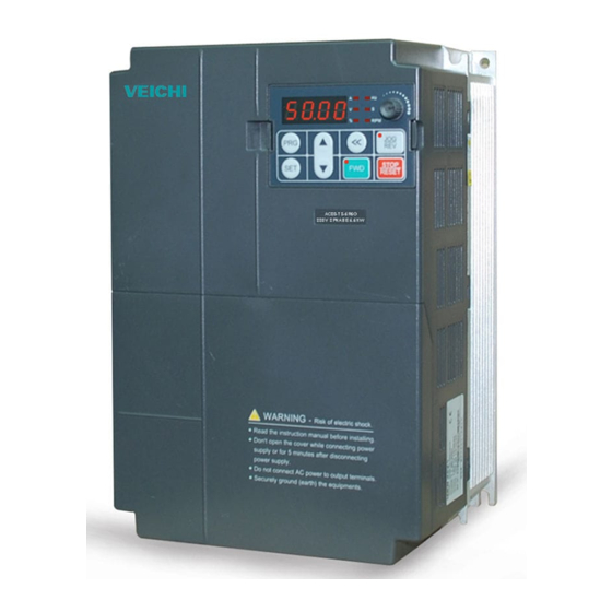
Summary of Contents for Veichi Electric AC60 series
- Page 1 M a n u a l Version V2.0 AC60 series frequency inverter...
- Page 2 For the best results and safe operations of the AC60 series, pls carefully read and keep this manual. Make sure it is handy for the ultimate user of the inverters for reference.
-
Page 3: Table Of Contents
Catalog Chapter one Safety Requirement and Cautions…………………………………1 1.1 Safety definition……………………………………………………………1 1.2 Safety requirement and cautions…………………………………………1 1.3 Cautions in utilization……………………………………………………5 1.4 Cautions in disposal ………………………………………………………7 Chapter two Purchase Inspection and Products Specification ………………8 2.1 Purchase inspection ………………………………………………………8 2.2 Nameplate and models illustration ………………………………………8 2.3 Product technique specifications………………………………………9 2.4 Inverter rated output current …………………………………………11 Charter three Installation ………………………………………………………13... -
Page 4: Table Of Contents
6.2 Exterior terminal parameters……………………………………………50 6.3 Special functions parameter……………………………………………58 Chapter seven Function Detailed Specification………………………………64 7.1 Basic parameters detailed specification……………………………64 7.2 External terminal parameters detailed description………………105 7.3 Special function parameters……………………………………………130 Chapter eight Abnormality Diagnoses and Processing…………………………152 8.1 Fault information and troubleshooting………………………………152 8.2 Common fault and processing methods…………………………………157 Chapter nine Overhaul and Maintenance…………………………………………165 9.1 Inspection and maintenance……………………………………………165 9.2 Components needed periodic replace……………………………………166... -
Page 5: Safety Definition
Chapter one Safety Requirement and Cautions To ensure safety of your health, equipment and property, please read this chapter carefully before use the frequency inverter and act in compliance with the instructions while carrying, installing, debugging, running and overhauling frequency inverter. 1.1 Safety definition Danger: it will cause danger of serious injuries and even death while operating against the rules... - Page 6 Danger Please install the frequency inverter on metal or other nonflammable material, and keep it away from the combustible material. Otherwise there is danger of fire; No unauthorized modification to the frequency inverter; Otherwise there is danger of damaged. Normal frequency inverter, which is not explosion-proof, can not be installed where with explosive gas or dust;...
- Page 7 1. If the damage to frequency inverter or other equipment is caused by improper wiring and utilization or unauthorized alteration, the user should shoulder all responsibilities. 2. Please make sure all wirings meet EMC requirement and satisfy safety standard in the local area; Please refer to recommendations in this manual or national standards of wire diameter to avoid accidents.
- Page 8 1. Please make sure that voltage grade of power supply is consistent with frequency inverter's voltage and then check whether the wiring is correct and firm, and whether there is short circuit in peripheral equipment's circuit. Otherwise it will damage frequency inverter and other equipments.
-
Page 9: Cautions In Utilization
1. Before running, please check and confirm the application range of the machine and equipments once more; Otherwise it will cause accidents. 2. Please don't touch the cooling fan and braking resistance to check the temperature; Otherwise there is a danger of getting burn. 3.Unprofessional workers are banned to check the signals in the running stage;... - Page 10 It is normal phenomena. 3. In application of AC60 series frequency inverter, you have to confirm all machine insulation to prevent damage to the equipment. Moreover, when the motor working in tough environment, please periodic inspect the electrical insulation to ensure the safety of the system work.
-
Page 11: Cautions In Disposal
1.4 Cautions in disposal When you dispose frequency inverter, please pay attention to: 1. Electrolytic capacitor: the electrolytic capacitor of main circuit or the printing plate may explode when they are burned. 2. Plastic: plastic incineration may generate toxic gases. 3. -
Page 12: Chapter Two Purchase Inspection And Products Specification
2. Check whether the details on the nameplate of frequency inverter are in accordance with your order. 3. AC60 series frequency inverter have undergone a rigorous testing and quality control before leaving the factory. Please check all of qualified certification, product manual and warranty cards. -
Page 13: Product Technique Specifications
AC60 - T 3 - 015 G / 018 P inverter series inverter type code AC60 general format general format injrction molding AC61 machine blower and water pump AC62 draw bench plastic machine draw bench code voltage class mid inverter governor three phase single phase fit power of motor ( kW ) - Page 14 Carrier 1.0-15.0KHz、Random carrier modulation frequency Torque 0~25.0% adjustable、auto torque upgrade、random V/F upgrade curve optional G、H、L model:150% for one minute, 180% for 2s, 200% instant jump. Maximum Z model: 150% for one minute, 180% for 30s ,250% instant Capacity jump. P model:120% for one minute, 150% instant jump. Acceleration 0.1-6500s Deceleration...
-
Page 15: Inverter Rated Output Current
Start, stop, positive and negative rotating , jog, Input order multi-steps speed, free parking, reset, acceleration signals and deceleration time choice, frequency settings channels choice, external malfunctions alarm External Relay output, the collector output, 0-10V output, output signal 4-20mA output, the frequency pulse output Overvoltage, undervoltage, current... - Page 16 0.75 18.5 1100 1260...
-
Page 17: Charter Three Installation
Charter three Installation 3.1 Installation environmental requirements 1.Ambient temperature: -10℃~40℃, good ventilation and heat dissipation. If the temperature is higher than 40 ℃. The frequency inverter should be derated to use. 2. Avoid vibration, free of direct sunlight and away from heat sources. 3. -
Page 18: Products Appearance And Components Title
8. Prohibit use of flammable, explosive gases, liquids or solids in a dangerous environment. 3.2 Products appearance and components titles 3.3 Mounting direction and space Frequency inverter should be installed in a well-ventilated indoor place, and adapt wall-mounted or closet-style vertical installation. Enough space with the surrounding adjacent items or baffle (wall) shound be preserved. -
Page 19: Dismantle And Install Tail-Hood
When several frequency inverters are installed in one cabinet, you should pay attention to the uniformity of each frequency inverter heat dissipation. While it adopts vertical juxtaposition installation, you should install deflector plate to avoid the heat of below inverter flows through the above inverter. Installation for multi frequency inverter 3.4 Dismantle and install tail-hood... -
Page 20: Dismantle And Install Keyboard
Installation: First the tail-hood upwardly inclines around 15 degrees and inserts the top fixed flat into the fixed hole in the front cover. Then slightly press the tail-hood downward. While your hear "Ka",it means that the tail-hood is into the place. Dismantlement: At the tail of the frequency inverter, there is a special dismantlement hole design. -
Page 21: Installation Size
Dismantlement: Put your finger into the keyboard dismantlement hole and pull the keyboard out. 3.6 Installation size(units:mm) 3.6.1 Installation size of machine with plastic cover... - Page 22 Frequency inverter Installation G: Constant torque load aperture P: Fans&pump load AC60-S2-R40G AC60-S2-R75G AC60-S2-1R5G 154.5 ф5 AC60-T3-R75G/1R5P AC60-T3-1R5G/2R2P AC60-T3-2R2G/3R7P AC60-S2-2R2G AC60-S2-3R7G 147.2 157.5 ф5.5 AC60-T3-3R7G/5R5P AC60-T3-5R5G/7R5P AC60-T3-7R5G/011P 167.5 ф7 AC60-T3-011G/015P 3.6.2 Wall-mounted machines installation size...
- Page 23 Frequency inverter Installation G: Constant torque load aperture P: Fans&pump load AC60-T3-015G/018P ф7 AC60-T3-018G/022P AC60-T3-022G/030P ф9 AC60-T3-030G/037P AC60-T3-037G/045P ф11 AC60-T3-045G/055P AC60-T3-055G/075P ф11 AC60-T3-075G/093P 3.6.3 Wall-mounted & Cabinet-mounted machines installation size...
- Page 24 VEICH the hole only to 93-132G STOP RESET back entering line hole bottom entering line hole Sepcification 1.User can enter line from bottom or back, detail according to below list. 2.Machine cabinet can be installed in ground with 4pcs foundation bolts. Size marker mode diagram(4) Frequency inverter G: Constant torque load...
- Page 25 In the table, H is the height of whole machine plus bottom section. The customers can choose installation made according to demand. Cabinet, lean against the well, or other installation mode are ok. And you can also choose hang-style machine and bottom section which consist the cabinet machine installed directly in installation slot or ground。...
-
Page 26: Operation Keyboard Size
3.7 Operation keyboard size 3.7.1. Single display keyboard size 35.1 86.7 84.2 22.2 3.7.2 Double display keyboard size 60.6 63.8 18.6... -
Page 27: Chapter Four Frequency Inverter Wiring
Chapter four Frequency Inverter Wiring 4.1 Wiring attentions 1. Wiring job can only be done by qualified professional personnel. 2. Before open the machine, make sure the power is safely cut off more than 10 minutes, otherwise there is a danger of shocking. 3.Absolutely prohibit the power input terminals to be connected to the frequency inverter U, V or W output terminals;Absolutely prohibit short circuit between the frequency inverter output terminals;Absolutely... - Page 28 interference of the frequency inverter output side to the other equipment, you have better to install a special noise filter at the output side of the frequency inverter and lay the output cables through the metal tubes. 8. If the frequency inverter need to frequently start, do not cut off the power, you should operate it through the control terminals (COM / FWD.
-
Page 29: Basic Wiring Diagram
power grid excesses the enable input voltage. If the power grid voltage excesses the inverter voltage limit, please supply power to frequency inverter with transformer. 17. The wire length between the frequency inverter and the braking unit should not exceed five meters; The wire length between braking unit and braking resistance should not exceed 5 meters. -
Page 31: Main Circuit Terminals
PB R T U V W ( ( ) ) 4.3.3 AC60 series three-phase 380V ( T3) 15G/18P machine main circuit terminals 4.3.4 AC60 series three-phase 380V(T3)18G/22P~75G/093P machine main circuit terminals R S T U V W POWER INPUT MOTOR OUTPUT 4.3.5 AC60 series three-phase 380V(T3)93G/110P~110G/132P machine main... - Page 32 R S T U V W ( ) (-) 4.3.8 AC60 series three-phase380V(T3)250G/280P~355G/400P machine main circuit terminals R S T 4.3.8 AC60 series three-phase380V(T3)400G/560P~560G/630P machine main circuit terminals R S T U V W ( ) 4.3.9 Terminal functions detailed description...
-
Page 33: Electrical Specifications Recommendation
4.4 Electrical specifications recommendation Electroma Opening Main wire Rated gnetic Type Motor (KW) switch specificat current (A) contactor ions AC60-T3-R75G/1R5P 0.75 AC60-T3-1R5G/2R2P AC60-T3-2R2G/3R7P AC60-T3-3R7G/5R5P AC60-T3-5R5G/7R5P AC60-T3-7R5G/011P AC60-T3-011G/015P AC60-T3-015G/018P AC60-T3-018G/022P AC60-T3-022G/030P AC60-T3-030G/037P AC60-T3-037G/045P AC60-T3-045G/055P AC60-T3-055G/075P AC60-T3-075G/093P AC60-T3-093G/110P AC60-T3-110G/132P AC60-T3-132G/160P AC60-T3-160G/185P AC60-T3-185G/200P AC60-T3-200G/220P AC60-T3-220G/250P AC60-T3-250G/280P... -
Page 34: Control Circuit Terminals
4.5 Control circuit terminals 4.5.1 Sequence of control terminals TC TA +24 COM REV X6 COM VS1 VS2 +10V TB Y1 Y2 FMD X1 X3 AO1 AO2 A+ B- -10V 4.5.2 Control terminals menu Categ Terminal name Function Common terminal Forward turn Short connect with (COM)is workable... - Page 35 4.6.1 AC60 series frequency inverter have powerful communications capabilities that enable frequency inverter communication with PC or PLC etc.equipment.Besides, a set of AC60 series frequency inverter communicate to control up to 31 sets of AC60 series frequency inverter; Machines whose power is under AC60-T3-011G/015P have build-in RS485 communication module.
- Page 36 Communication wire must be shield twisted-pair,which is separated from the control wires. RS485 communication modules are plug-in type installation. RS485 communication modules plug-in type installation as shown in the following fig.: On the right side of the connection terminal in the controlboard, there are a group of jumper terminals J1, J2 and J3 which is chose to work with software to decide A02 output mode.
-
Page 37: Backup Circuit
4.7 Backup circuit If the frequency inverter emergence break off for fault, it will cause great loss or other unexpected fault occurred. Please add this circuit standby to ensure safety. -
Page 38: Chapter Five Keyboard Operation And Usage
Chapter five Keyboard Operation and Usage 5.1 Keyboard layout and function specification AC60 series frequency inverter has two kinds of keyboards: the single display type for machine below 011G/015P and the double display type for machine above 015G/018P. 5.1.1 Single display keyboard layout and function specification... - Page 39 While run/stop is controlled by keyboard, press this key, the Forward key inverter forward rotate. While run/stop is controlled by keyboard, press it, machine will Jog/Reverse key reverse if this key is defined as REVERSE and machine will jog if this key is defined as JOG. Machine stops if press it while run/stop is controlled by keyboard.
- Page 40 Press to modify parameter while in menu interface.Press again to confirm aftr modify. While standby or Confirm/modifykey running, press to change LED monitoring items at stop Select parameter group in menu interface. Modify parameter while in modify interface. Modify given Up/down key frequency or PID or given torque while at standby or monitoring state(While given frequency or PID or...
-
Page 41: Indicating Lamp Meaning Specification
5.2 Indicating lamp meaning specification 5.2.1 Single display keyboard indicating lamp meaning specification Name state meaning Flash 4 digit digital display value is given frequency. 4 digit digital display value is output frequency. 4 digit digital display value is output current actual value. -
Page 42: Keyboard Operation Mode
5.3 Keyboard operation modes 5.3.1 Menu’ structure and operation The parameter setting of the AC60 series frequency inverter adopts three groups of menus structure, which enable the user to inquire and modify the parameter quickly. Three groups of menus are basic parameter、external terminal... - Page 43 5.3.2 Switch of display mode The AC60 series frequency inverter under stopping state or operation state can display various monitoring parameters by the LED nixie light. Inverter with two kinds of keyboard both can set the concrete display parameters by [E-06,E-07]under stopping state or operation state.They both can set the...
- Page 44 2. Double display keyboard cycle switch the display of monitoring parameter mode:...
- Page 45 5.3.3 Parameter setting mode Perfect performance of the frequency inverter is on the premise that the AC60 series frequency inverter parameters are set properly. Take parameters [F-08] modification as an example as follow (Terminal operational control mode is changed from the standard operational control mode to the second-line-style...
- Page 46 2. Double display keyboard parameter setting mode:...
-
Page 47: Chapter Six Functional Parameter Table
Chapter six Functional Parameter Table “●” :Means that the parameter can be revised during frequency inverter in a running state; “〇” :Means that the parameter can not be revised during frequency inverter in a running state; “×” :Means that the parameters can only be read and can not be changed; “–”... - Page 48 running 12:Terminal selection 0: keyboard number setting 1:Keyboard potentiometer 2 : Terminal VS1 voltage signal,0~10V 3 : Terminal AS current signal,4~20mA 4 : Terminal VS2 voltage Frequency given signal,-10~10V E-03 auxiliary channel 〇 103H 5:Terminal pulse signal selection 6 : RS485 communication port 7:...
- Page 49 Keyboard first 0:Given frequency display monitoring 1:Output frequency E-06 selections: 2:Output current ● 106H 3:Input voltage 4:Output voltage 5:Mechanical speed Keyboard second 6:PID given value display monitoring 7:PID feedback value selections: E-07 ● 107H Keyboard REV/JOG 0:REV E-08 function ● 108H 1:JOG options...
- Page 50 E-19 113H Reserve E-20 Carrier frequency 0.7KHz~15.0KHz ※ ● 114H LED single digit: Carrier frequency associated with the output setting 0 : Output frequency correlation invalid 1 : Input Frequency correlation valid LED “10” digit: Carrier temperature correlative Carrier E-21 setting 0000 ●...
- Page 51 frequency 2 : First rotate speed tracking then restart Power cut restart 0:invalid E-31 ● 11FH options 1:valid Power cut restart E-32 ● 120H 0.0~10.0 second waiting time Free stop E-33 0.00~60.00Hz 0.50 ● 121H frequency 0:deceleration E-34 Close-down mode close-down ●...
- Page 52 running 1:close-down based on the temperature, running while operation 2 : fans stop while close-down, running related temperature LED 0 digit: overvoltage protection options 0:invalid 1:valid digit : earth short-circuit protection detection 0:invalid 1:valid LED 100 digit : input Frequency inverter Open-Phase protection 0※1...
- Page 53 protection values Motor rated E-56 100~1140V ※ 〇 138H voltage Motor rated E-57 0.1~1000A ※ 〇 139H current Motor rated E-58 25.00~400.0Hz 50.0 〇 13AH frequency Motor rated E-59 0~65000 1460 ● 13BH rotating speed Frequency inverter E-60 output voltage 50~100% 100% 〇...
-
Page 54: Exterior Terminal Parameters
6.2 Exterior terminal parameters: seria range of setting and Function description numbe meaning 0:invalid positive Input signal options F-01 〇 201H operation 1(X1) : Negative operation 3:free stop Input signal options 4:fault reset F-02 〇 202H 2(X2) 5 : multi-step speed contol1 6 :... - Page 55 channel selection terminal 2 18:frequency setting channel selection terminal 3 19:frequency setting channel selection terminal 4 20 : program running suspension 21 : program running restart 22 : timer trigger terminal : timer reset terminal 24:timer Auto-Nulling terminal 25:Counter clock input terminal LED 0 digit:free close-down...
- Page 56 shutdown instantaneous frequency, then UP / DW regulate 2: First to [F-70], then UP / DW regulate LED 100 digit:keyboard STOP/RESET button effective range selection 0 : only keyboard control effective 1 : all control mode effective LED 1000 digit : after fault reset, terminal operation mode...
- Page 57 7 step speed F-15 35.00 ● 20FH setting 7X 8 step speed F-16 40.00 ● 210H setting 8X 9 step speed F-17 45.00 ● 211H setting 9X 10 step speed F-18 50.00 ● 212H setting 10X 0.00Hz ~ upper limit 11 step speed F-19 30.00...
- Page 58 3 : frequency arrive detection 4 : frequency level signal detection 5:be operating 6:reversal operation 7:frequency undervoltage 8:overload pre-alarm 9:output frequency reach upper frequency limit 10:output frequency reach lower frequency limit 11 : exterior fault clost-down Output terminal ● 220H F-32 12:timer times up 13 :...
- Page 59 Overload pre-alarm ● 224H F-36 50~200% range Overload pre-alarm ● 225H F-37 0.0~20.0 second delay time ● 226H F-38 Timer setting values 1~65000 second Counter maximum 1000 ● 227H F-39 1~65000 Value Counter setting 1~Counter maximum ● 228H F-40 Value value VS1 terminal input 0.00...
- Page 60 limit Impulse input 10.00 ● 236H F-54 frequency upper [F-53]~50.00KHz limit Impulse input 1.00 ● 237H F-55 0.01~5.00 frequency gain Input frequency 0.00 ● 238H F-56 0.00Hz~[F-57] lower limit setting Input frequency [ F-56 ] ~ maximum 50.00 ● 239H F-57 upper limit setting frequency...
-
Page 61: Special Functions Parameter
constant 0:output signal close : output Output terminal ( AO1) F-60 ● 23CH frequency/speed selection 2:output current : given frequency/speed 4:PID given quantity Output terminal ( AO2) ● 23DH F-61 5:PID feedback selection quantity 6:DC bus voltage 7:output voltage 0:frequency pulse output (AO2)output signal 1:0~20mA... - Page 62 Facto Series Function Range of setting values number description and meaning setti Free-setting H-01 0.0% ~[H-03] 〇 301H voltage V1 Free-setting H-02 0.0Hz~[H-04] 0.00 〇 302H frequency F1 Free-setting H-03 [H-01~H-05] 25.0 〇 303H voltage V2 Free-setting H-04 [H-02~H-06] 12.50 〇...
- Page 63 setting 0 : exterior terminal VS1:0~10V 1 : exterior terminal PID controller AS:4~20mA H-13 feedback signal 〇 30DH 2:exterior terminal source VS2 (bipolar failure) 3:exterior terminal pulse signal PID preset 0.00HZ ~ upper H-14 0.00 ● 30EH frequency frequency limit preset H-15 frequency...
- Page 64 selection lower limit Upper limit H-30 demarcative values ~ 100.0 ● 31EH demarcative values 100.0% lower limit 0.0%~Upper limit H-31 ● 31FH demarcative value demarcative values 0: single cycle (time in seconds) 1 : continuous cycle (time in seconds) 2:single cycle, continuous running (time in seconds) H-32...
- Page 65 direction 2:Forward Rotating; ace&dece time acceleration time 3/deceleration time 3 Fourth step speed H-38 direction ● 326H 3:Forward Rotating; ace&dece time acceleration time Fifth step speed 4/deceleration time 4 H-39 direction ● 327H 4:Reverse Rotating; ace&dece time acceleration time Sixth step speed 1/deceleration time 1 H-40 direction...
- Page 66 step speed H-52 10.0 ● 334H operation time T3 step speed H-53 10.0 ● 335H operation time T4 step speed H-54 10.0 ● 336H operation time T5 step speed H-55 10.0 ● 337H operation time T6 step speed H-56 10.0 ●...
- Page 67 0:1200 bps 1:2400bps H-69 〇 345H Baud rate 2:4800 bps 3:9600bps 4:19200bps Communication H-70 setting frequency 0.01~5.00 1.00 ● 346H ratio Communications ● 150 H-71 347H 0.0~6500.0 second 10.0 timeout time RS485 Communication 0:close-down H-72 ● 348H disconnection 1:Continued operation action mode H-73 Response delayed...
-
Page 68: Chapter Seven Function Detailed Specification
Chapter seven Function Detailed Specification 7.1 Basic parameters detailed specification Execute commands given Factory E-01 Range :0~2 channel selection setting:0 Select channels which are used to accept operation and stop orders and the running direction. When restore factory setting,the setting values can not be changed. - Page 69 exterior terminal operation orders will be blocked while the inverter close-down at the same time. At this moment, you need to unlock exterior terminal close-down order, then the exterior operation order will be valid again. It is same with the communication control. 3, Under keyboard control, the direction order of the exterior terminals (REV) precede over the direction order of the keyboard;...
- Page 70 3:Terminal AS current signal 4~20mA The given frequency of the main channel is determined and amended by the input analog quantity of the control terminal (VS); If you want more detail about the input analog quantity and the corresponding relation of the frequency and input analog quantity filtering time ,please refer to parameter[F-50、F-51、F-52、...
- Page 71 8:Normal PID operation If you select this channel, it can constitute normal PID closed-loop control system. The parameter[H-16] can be modified by Up-down key. 9: Constant pressure PID control If select this channel, it can constitute constant pressure PID control ( constant pressure supply water etc. ) closed-loop control system.The parameter[H-16] can be modified by Up-down key.
- Page 72 with "0" frequency when arriving at that section speed. Program running and multi step speed operation are designed to achieve inverter variable-speed operation under a certain laws. Among the multi step operation, multi steps speed switch and running direction change are achieved through the different combination of exterior multi steps speed control terminal(such as X1、X2、X3、X4)and(FWD)...
- Page 73 RS485 communication port ascend 、descend control Normal PID operation constant pressure control Program run swing frequency operation Tips: Valid frequency selection terminals combinations are 0 to 11 (10 digits). If not in this range, frequency inverter output 0 frequency; "OFF" in the table said corresponding terminal and (COM) disconnected. "ON"...
- Page 74 input terminal (AS). 4: Terminal VS2 voltage -10~10V The given frequency of the auxiliary channel is determined and amended by the control panel analog quantity input terminal (VS2). 5:Terminal pulse signal The given frequency of the auxiliary channel is determined and amended by the control panel signal input terminal (PUL)...
- Page 75 Tips: The main frequency given channel and the auxiliary frequency given channel can be set as the same channel. In such circumstances, the corresponding relationships between the frequency setting values and input signal are rather special, so it needs to take consider of the both characteristic.
- Page 76 terminal VS2 ([F-48]is “1”), polarity frequency gived by (VS2) and frequency gived by another channel carry out symbol calculate based on the combination method selected. After calculation, the absolute value is frequency value and the symbol decides the motor direction. When opened bipolar...
- Page 77 0:Reverse This key is defined as reverse key(at this moment ,keyboard functional indicator REV / JOG do not light). When the operation order given channel is set as keyboard control, press this key ,frequency inverter will reverse operate. 1:Jog This key is defined as jog key(at this moment ,keyboard functional indicator REV / JOG light.
- Page 78 Maximum frequency, upper frequency limit and lower frequency limit should be cautiously set base on the nameplate parameter of actual control motor and the need of the running conditions. Except of upper limit and lower limit, the output frequency while inverter running are limited by the parameterized value of the start-up frequency、...
- Page 79 setting:※ E-15 Acceleration、 range:0,1 Factory Deceleration mode setting:0 Acceleration time is the time consumed while the output frequency accelerate from 0.00Hz to the maximum frequency. Deceleration time is the time consumed while the output frequency decelerate from the maximum frequency to 0.00Hz. Without annotate circumstances, usually take the acceleration and deceleration time 1 as the default acceleration and deceleration time.
- Page 80 startup 、close down 、positive/negative turning, acceleration and decelerate process. 0:Beeline Generally applicable to common type load 1:S curve S acceleration、deceleration curve is supplied to mitigate noise, vibration decrease start-stop impact while acceleration/deceleration, or supplied to diminish torque while low frequency, or supplied to accelerate in short-time while high frequency.
- Page 81 V/F curve mode Used to select the type of V/F curve, in order to meet the need of different load characteristic; This series frequency inverter supply four kinds of fixed V/F curve and one kind of auto-definition V/F curve. Constant torque curve is optional for general load and descend torque curve is optional for square torque load sucu as water pumps, etc..
- Page 82 upgrade. Low frequency torque voltage upgrade compensation changes by follow the change of the motor stator current. The greater the stator current is the higher lower frequency torque voltage upgrades. E-20 Carrier frequency range:0.07KHz~15.0KHz Factory setting:※ This function is mainly used to improve situation of the noise and vibration which possible occur during the inverter operation .When the carrier frequency is high, the current waveform is very ideal and the motor noise is very small.
- Page 83 Carrier frequency Motor noise jammer Switch loss 1KHz high 8KHz high high 15KHz Below 3.7KW: When the carrier frequency is 6 KHz, rated current is the maximum output current. 5.5KW-22KW:When the carrier frequency is 3 KHz, rated current is the maximum output current.
- Page 84 1:module temperature correlation is valid When inverter temperatures rise, frequency inverter automatically reduces the carrier frequency; When inverter temperature reduces, carrier frequency will rise. This function can help the frequency inverter to reduce the switch loss of the power device to prevent frequent alarms for inverter overheat fault. LED 100 digit:PWM mode selection 0:Fixed PWM mode Motor noise frequency is fixed.
- Page 85 frequency compensation amount should base on motor rated slip; The compensation value should not be set too high. E-23 Energy saving operation Range :0,1 Factory selection setting:0 0:Invalid 1:Valid In operation, inverter can auto-calculate the best output voltage to load according to the load condition to save the electricity.
- Page 86 The jog frequency has the highest control priority (terminal jog). Namely under any condition, when jog instruction is valid, the inverter immediately run from current running frequency to the jog frequency based on jog accelerates/decelerates time. The jog accelerates/decelerates time is defined as same as accelerates/decelerates time, which can be controled through the keyboard、control terminal or jog operation order of RS485 Attention: The setting value of the jog running frequency is only limited...
- Page 87 Tips: in the process of frequency inverter start and speed up, when the given frequency is lower than start-up frequency, frequency inverter output is zero. E-30 Start-up selection Range :0~2 Factory setting:0 0: Start by the start-up frequency [E-28] the start-up frequency setting and [E-29] start-up frequency duration setting control frequency inverter start;...
- Page 88 2: Speed track to restart Frequency inverter detects the motor speed firstly, then run from the origin speed to the given frequency according to the acceleration / deceleration time. While the frequency inverter free stops or instantaneous power cut restarts, regardless it tracks speed to restart or not, frequency inverter will restart at the speed detected.
- Page 89 In the exterior terminal control state, if power cut, after electrify, the control command of the exterior terminal (FWD/REV)is invalid; The control command is valid only when the running order reset operation on the exterior terminal is detected. Must after detecting the operation of the exterior control terminal has reset running command, then the control command is valid.
- Page 90 E-33 Free stop frequency Range :0.00~60.0Hz Factory setting:0.50Hz While the frequency inverter receives the stop order in the deceleration stop mode, it will decelerate to the free stop frequency according to the deceleration time, then stops output and the motor free stops. Tips: This function is valid only while stop , invalid in the process of FOR/REV switching.
- Page 91 unit(above 18.5G/22P) can choose external braking unit and braking resistor. This mode is mainly suitable for occasions need quick braking while stop. 1: Free stop After receiving the stop order, frequency inverter will block the output and motor will free run to stop. If users choose this method, frequency inverter generally coordinate with the external mechanical brake to fulfill quick stop.
- Page 92 Namely DC braking function is invalid. DC braking initial frequency in stop stage is what frequency when the frequency inverter decelerate, frequency inverter will stop output and start DC braking function. If the ouput frequency is less than the DC braking initial frequency in stop stage while running, the frequency inverter will stop output and start DC braking while stop.
- Page 93 range which is based on the jumping frequency. Tips: 1、During the process of acceleration and deceleration, the output frequency of frequency inverter will normally overlap the jumping frequency district. Do not set three overlap or nested jumping frequency ranges. 2 、 Jumping frequency is valid for jog 、 multi-step speed and swing frequency operation.
- Page 94 Fault auto-restore times: 0: closed This function is closed, it has not automatic reset function, only can be reset manually. 1-10 open This function is open, 1-10 is the times of auto-restore after fault (defined as the most auto-restore times after the each fault) During the frequency inverter operation, load undulation 、power grid voltage fluctuation or other accidental factors may bring fault stop.
- Page 95 Tips: users should be cautious to consider the start characteristic of the mechanical devices during the manipulation. In occasions where it can not start with load or it must alarm immediately while frequency inverter has no output, please think carefully before use this function. E-45 Warm-up time Range :0.0~6500 second...
- Page 96 order and frequency inverter will operate as the forward rotating direction. E-47 FOR/REV dead time Range :0.0~10.0 second Factory setting : 0.0 second This function is defined as the waiting time in 0.0Hz while frequency inverter in the transition process from forward rotating to reverse, or from reverse to forward rotating.
- Page 97 the temperature is over 45 degree Celsius and fan stops when the temperature is lower than 40 degree Celsius. Fan runnes immediately when the frequency inverter running. 2. When frequency inverter close down, fan stops. And fan running relates to the temperature While the frequency inverter is in operation, whether fan run or no relates to the module temperature.
- Page 98 “Err1”and stop output. The motor free stops. And fault output terminal will act. This function is valid only for 7.5P or above power machine of AC60 series. The factory setting of this parameter is set based on the concrete types. This function is invalid for 5.5G or below power machine.
- Page 99 Current limit running mode is frequency inverter will run as output current limit mode while in overload 、overheat situation. If the current is over the limiting value, frequency will reduce the output frequency to reduce the load current; When the inverter overload, pre-alarm signal can be output by the output terminal[F-30~F-32].
- Page 100 This parameter is defined as the ratio of stall protection current value to motor rated current value ration. G model factory setting:160% P model factory setting:120% Stall protection current limit function is real-time monitoring the load current during acceleration, auto-limit it not to exceed the current limit setting value(frequency inverter controls the output current by stopping acceleration or reducing output frequency), to prevent the fault trip which caused by excessive currents.
- Page 101 This function is only valid for the machine with build-in braking modules; Machines below 15G/18P of AC60 series frequency inverter have standard braking modules. Machines below 5.5G/7.5G have standard braking modules and braking resistor. Braking unit and braking resistor are optional parts of other...
- Page 102 have standard braking modules, but do not have resistors. Customers need to buy the braking resistor separately if necessary. Energy-consumed braking action ratio This parameter is used to define the average value of the voltage on braking resistor when the braking unit acts. The voltage on braking resistor is voltage PWM wave.
- Page 103 0:G model,suitable for constant torque load. 1:P model, suitable for variable torque(such as fan、water pump load). The AC60 series frequency inverter adopts G/P in one mode. The power of the motor adaptor used in the constant torque load (G model) is one level lower than that used in fan、water pump load(P model).
- Page 104 inverter detects the frequency during the period of tracking the speed. For big inertia load, lengthening the speed tracking stability time properly can reduce the instant impact current while speed tracking starting. E-63 Parameter change Range:0 ~ 2 Factory protection setting:0 0:All the parameters changeable Except for the parameters only for...
- Page 105 E-65 Factory password Range :0~9999 Factory setting:0 Manufacturer inquiry parameters. E-66 Information inquiry Range :0 ~ 2 Factory setting :0 0:No operation 1:State monitoring inquiry Select this function to enter monitoring menu(group C parameters) ,and inquire each state parameters of the frequency inverter.
- Page 106 C-14 Input terminals See belowing C0EH connect/disconnect status diagram C-15 Input terminals See belowing C0FH connect/disconnect status diagram Terminal VS1 input value C-16 0.1v C10H Terminal AS input value C-17 0.1mA C11H Terminal VS2 input value C-18 0.1v C12H Terminal pulse input value C-19 ※...
- Page 107 Output terminal connect/disconnect state schematic diagram 2: Fault information inquiry After inquiry setting, can set LED display below information circularly by the keyboard up、down keys. Seria Definition Remark numbe For details, pls see fault Er.01 The latest fault information E01H information code table The cumulative running time Er.02...
- Page 108 latest fault Running direction while the Er.08 0.Forward 1.reverse E08H latest fault 0.close down 1.stable speed Running status while Er.09 2.acceleration E09H latest fault 3.deceleration 0. Normal 1.only voltage amplitude limit 2. only Protection status while the Er.10 current amplitude limit E0AH latest fault...
-
Page 109: External Terminal Parameters Detailed Description
System fault o.H. Inverter interior overheat Feedback sensor fault(fault annal will not note) Err1 Input side open-phase Err2 Output grounding Current detected fault(fault annal will not Err3 note) Err4 Inverter exterior fault Swing frequency running parameter setting Err5 error Keyboard communication fault(fault annal Err6 will not note) Reserved(Seek the technical support)(fault... - Page 110 Separately define control terminal(X1-X6)functions. Short connect with the terminal(COM)is valid. Definition Function description Invalid(can reelection) This port unused Forward jog operation Jog order input port. Terminal jog Reverse jog operation orders have the highest priority Free stop Free stop order input port When breakdown, exterior reset order Fault reset input port...
- Page 111 inverter operates according to this frequency; Exterior fault alarm Input port of exterior fault signal Acceleration/deceleration time selection terminal 1 See the below fig. Acceleration/deceleration time selection terminal 2 Frequency main channel selection terminal 1 When [ E-02 ] selection is “ 12 ” , Frequency main channel frequency input main channels are selection terminal 2...
- Page 112 Terminal 2 Terminal 1 Acceleration/deceleration time selection Acceleration time 1 and deceleration time 1 Acceleration time 2 and deceleration time 2 Acceleration time 3 and deceleration time 3 Acceleration time 4 and deceleration time 4 Short connect with (COM)is “ON” ,disconnection is “OFF” F-07 Input signal action mode Range :0000 ~...
- Page 113 frequency inverter, frequency inverter will be in the stop and locking state. At this moment, if you want to use the terminal or RS485 operation order channel to restart the frequency again, you must send the stop order by the selected channe. The frequency inverter can rerun after unlock. LED 1000 digit:After fault reset, terminal operation mode selection 0:Terminal control to power on directly 1:Terminal control to power off firstly,then start...
- Page 114 In three linear control operation, "SB1”is stop button which is usually connected, "SB2" is running button which is usually disconnected, both "SB1”and "SB2"are valid at pulse edges; "K" is the operation direction selection button; "D (X)" is the multi-function terminal; (X1 - X6) are defined as the terminals of the three-linears operational control (11) function.
- Page 115 F-11 3 step speed Range :0.00Hz~upper limit Factory setting 3X frequency setting:15.0Hz F-12 4 step speed Range :0.00Hz~upper limit Factory setting 4X frequency setting:20.0Hz F-13 5 step speed Range :0.00Hz~upper limit Factory setting 5X frequency setting:25.0Hz F-14 6 step speed Range :0.00Hz~upper limit Factory setting 6X...
- Page 116 choose the multi-step speed running mode, they need to set more than four multi-function input terminals as multi-step control terminal. ( ON/OFF between the four terminals and (COM) determines the running step speed. Its operation and direction is controlled by the running signal and direction given by the operation given channel[E-01].
- Page 117 F-24 Acceleration time 2 Rang:0.1~6500.0 second Factory setting: ※ second F-25 Deceleration time 2 Rang:0.1~6500.0 second Leave factory value: ※ second F-26 Acceleration time 3 Rang:0.1~6500.0 second Factory setting: ※ second F-27 Deceleration time 3 Rang:0.1~6500.0 second Factory setting: ※ second F-28 Acceleration time 4 Rang:0.1~6500.0 second...
- Page 118 Settin Definition Function description g value Relay output terminal Factory F-30 Range :0 ~ 19 (TA、TB、TC) setting :1 F-31 Output terminal Y1 Range :0 ~ 19 Factory setting :3 F-32 Output terminal Y2 Range :0 ~ 19 Factory setting : Zero frequency When the frequency inverter is running,...
- Page 119 frequency of frequency inverter is lower than the frequency detection level, it outputs invalid signal after [F-35] delay time setting. When frequency inverter is in the running Running state, it outputs signal. When frequency inverter reverse,it outputs Reversal running signal. Inverter When the frequency inverter displays “LU”...
- Page 120 counter clear to “0”. When the counter reach the setting values, output terminal output valid signal. When Counter reach counter further counts to surpass the maximum setting values values and the counter clear to zero, this output signal abolishes. feedback When the PID feedback quantity reaching quantitative upper...
- Page 121 F-33 Frequency reach Range :0.00~50.00Hz Factory setting: detection amplitude 1.00 Hz F-34 Output frequency level Range :0.00~400.0Hz Factory setting: detection 30.00 Hz Output frequency Factory setting: F-35 Range: 0.0~20.0second detection delay time 0.0 second When the output frequency of frequency inverter reaches the given frequency, it outputs signal;...
- Page 122 If the output current continues to be over the setting level of the parameter [F-36] ,after the delay time[F-37] ,the output terminal outputs valid signal. In the same way,when the output current is lower than the setting level of [F-36] ,after the delay time[F-37] ,the output terminal outputs invalid signal.
- Page 123 This parameter stipulate the counting action of the interior counter, clock terminal of the counter is selected by the parameter[F-01~F-06]. When the count value to the exterior clock reaches[F-39]setting value, in the corresponding output terminal, it outputs a valid signal with a width equal to exterior clock cycle.
- Page 124 VS1 terminal input voltage lower limit This function defines the minimum signal the analog input terminal(VS1) receivse. Frequency inverter will automatically filter the voltage signal whose value is lower than this value. VS1 terminal input voltage upper limit This function defines the maximum signal the analog input terminal(VS1)receives.
- Page 125 will automatically filteres the voltage signal whose value is higher than this value. VS2 terminal input voltage gain S2 This function is used to amplify or reduce the (VS2) terminal analog value. VS2 terminal input zero offset This function is used to adjust the (VS2) terminal zero point in the bipolar control mode;...
- Page 126 calculation based on the combination mode selection. Negative voltage and frequency DW signal are negative signal. All other input signals of VS2 are positive signal. If calculation result is positive, the machine forward rotates; If the calculation result is negative, machine reverses. 2: Bipolar adjust valid, direction control invalid: In two channels combination, it used to add or reduce frequency of another channel.
- Page 127 Tip : When (VS2) is used as PID given or feedback channel, the function of bipolar is invalid. At this moment, the usage of (VS2) terminal is the same with the (VS1) terminal. Namely, when (VS2) <0, frequency inverter think the input of this port is 0.
- Page 128 AS terminal input current upper limit This function defines the maximum signal which received by the analog input terminal(AS), frequency inverter will automatically filters the current signal whose value is higher than this value. AS terminal input current gain This function is used to amplify or reduce the (AS)...
- Page 129 Terminal input upper Factory Range : [F-56]~maximum F-57 limit setting setting:50.00 frequency frequency These two parameters stipulate the corresponding relation between the exterior input analog quantity, upper/lower limit of the pulse signal and the frequency. F-58 Input signal Range :0000~1111 Factory setting:...
- Page 130 Terminal analog input Factory setting: F-59 Range: 0.01~5.00 second filtering time constant 0.50 second This is defined as the size of the input analog quantity signal filtering, for the purpose of eliminating the interference signal. The longer filtering time is, the stronger anti-interfere ability is, but the respond speed slow down;...
- Page 131 F-62 ( AO2 ) output signal Range :0 ~ 3 Factory selection setting :3 2:Output current 3:Given frequency/speed 4:PID given quantity 5:PID feedback quantity 6:DC bus voltage 7:Output voltage Tips: when (AO2)port is frequency pulse output or 4~20mA output, “0%” corresponding output quantity is not zero.
- Page 132 0:Frequency pulse output Factory settings is 0.2KHz~10.0KHz; 1:0~20mA 2:4~20mA 3:0~10V Tips: after the software select the output mode, user need to select the short connect mode of the terminal pin J1,J2,J3. The concreter selection ways as follows: When select frequency pulse output mode, pls short connect the J1,disconnect the J2、J3.
- Page 133 F-66 ( AO2 ) output signal zero Range :-10%~10% Factory adjust setting:0% They are used to adjust the output signal zero point of(AO1)terminal and(AO2)terminal. It is invalid to adjust this value when(AO2) is frequency pulse output,. Keyboard potentiometer input voltage lower limit This function defines the Keyboard potentiometer Factory...
-
Page 134: Special Function Parameters
During the ascend/descend control, frequency inverter input the initial Ascend/descend Range :0.00Hz~frequency Factory F-70 terminal preset upper limit setting : 0.00Hz frequency frequency after operation. Only valid when [F-07]LED 10 digit is set as “1” or“2”. When the [F-07]LED 10 digit is set as“1”, this parameter will save the instantaneous frequency at stop in ascend/descend process, which can be reviewed or modified after stop. - Page 135 H-01 Free-setting Range:0.0%~[H-03] Factory setting: voltage V1 0.0% H-02 Free-setting Range:0.00Hz~[H-04] Factory setting: frequency F1 0.00Hz H-03 Free-setting Range: [H-01~H-05] Factory setting: voltage V2 25.0% H-04 Free -setting Range: [H-02~H-06] Factory setting: frequency F2 12.50Hz H-05 Free-setting Range: [H-03~H-07] Factory setting: voltage V3 50.0% H-06...
- Page 136 This parameter setting must satisfy the following conditions: 0≤F1≤F2≤F3≤F4≤F5≤ maximum frequency upper limit;0≤V1≤V2≤V3≤V4≤ V5≤100% V1、V2、V3、V4、V5 is base on the frequency rated output voltage. H-11 PID output Range :0,1 Factory characteristic setting :0 PID control is a common method used in the process control. By series calculation on the difference between the feedback quantity of controlled object and the frequency PID given quantity, such as proportion, integral, differential,and so on, it adjusts the output frequency of frequency inverter...
- Page 137 0:Positive characteristic Suitable for occasions where maintains the PID balance by reducing the frequency inverter output frequency while the PID feedback quantity is greater than PID given quantity. Such as constant pressure water supply, gas supply and take-up tension control. 1:Negative characteristic Suitable for occasions where maintains the PID balance by enhancing the frequency inverter output frequency while the PID...
- Page 138 0:Keyboard potentiometer Given by the keyboard potentiometer analog signal. 1:PID keyboard number given When applied to normal PID,setting by the [H-16]. 2:Exterior exterminal VS1 Given by the exterior exterminal(VS1) (0V~ 10V)analog signal. 3:Exterior exterminal AS Given by the exterior exterminal(AS) (4~ 20mA)analog signal.
- Page 139 Range:0.00Hz~frequency PID preset Factory setting: H-14 upper limit frequency 0.00 Hz PID preset Factory setting: H-15 frequency operation Range:0.1~6500.0 second 0.0 second time This function is defined as this: after PID running , frequency inverter will accelerate to the PID preset frequency [ H-14 ] according to the acceleration \deceleration time 1 firstly and run for PID preset frequencies running time [H-15] , then run according to the PID closed-loop...
- Page 140 H-16 PID keyboard number Range :0.0%~100.0% Factory given setting:50.0% Only when[H-12]setting is“1”,this parameter is valid;Take the sensor largest range[H-18] as a benchmark; When this parameter is changed, PID given value of monitoring target will automatically synchronize change. H-17 Feedback channel gain Range :0.01~5.00 Factory setting :1.00...
- Page 141 feedback voltage is 4.5V, the largest range of the sensor is 20mpa Nixie light display value =(4.5-0.5)×20/(9-0.5)=9.4mpa H-19 Proportion gain P Range :0.1~100.0 Factory setting:20.0 H-20 Integral time constant Range :0.1~100.0 Factory settin: second 2.0second H-21 Differential gain D Range :0.0 ~ 10.0 Factory setting:0.0 The adjustable parameters, which are control by PID,should be set based...
- Page 142 H-22 Sampling period Range : 0.01 ~ 60.00 Factory setting: second 0.10 second This parameter is only valid for the sampling period of feedback quantity. The adjuster calculates for one time in each sampling period. The shorter sampling period is, the quicker it responds. H-23 PID control deviation Range:0.0%~20.0%...
- Page 143 H-24 Start threshold Range:0.0%~sleep threshold Factory setting:0.0% H-25 Dormancy Range: start threshold~ Factory threshold 100.0% setting:100.0% Start threshold: After the frequency inverter enters dormant state, PID feedback quantity must be lower than the start threshold. Frequency inverter can restart again; If the start threshold is set too high, the frequency inverter maybe frequently start and stop;...
- Page 144 Alarm upper Range :alarm lower limit Factory H-26 limit value value~100.0% setting:100.0% Alarm lower limit Range :0.0%~alarm upper Factory H-27 value limit value setting :0.0% While PID feedback reaches or exceeds the setting value, if any output terminals[F-30~F-32]is set as “15” (PID feedback quantity upper limit alarming, it outputs alarm signal;...
- Page 145 1:Close down In the process of PID adjustment,while system detectes sensor open circuit, this parameter is used to choose whether frequency inverter stop working. If choose working on ,frequency inverter will cancel closed-loop control, with PID given values as frequency output; If choose close down, when the system detects the alarm which is mentioned above, the inverter will stop output and display the malfunction information immediately.
- Page 146 time are selected by parameter [H-35 ~ H-49]; Run time is set up by parameter [H-50 ~ H-64]; The time unit is second.While the first step time up, it shifts to the next step speed. The time、direction、acceleration\deceleration time of each step speed can be set;...
- Page 147 parameter [H-35 ~ H-49]; Running time is set up by parameter [H-50 ~ H-64]; The time unit is minute; The others are identical with mode "1". H-33 Program run breakpoint restore Range :0,1,2 Factory mode selection setting :0 0: Running at the first step speed 1: Continue to run as the breakpoint operation frequency and time again.
- Page 148 next time. If need to ensure that, after restoring from power down, the frequency inverter continues the state before power down. this parameter should be set as “1” 。...
- Page 149 Factory H-35 step speed direction Range :0~7 setting acceleration 、deceleration time :0 Factory H-36 step speed direction Range :0~7 setting acceleration 、deceleration time :1 Factory H-37 step speed direction Range :0~7 setting acceleration 、deceleration time :2 Factory H-38 step speed direction Range :0~7 setting...
- Page 150 During the program running, rotation direction and acceleration 、 deceleration time of 15 steps can be set up respectively. Setting Definition details value series Forward; acceleration time 1/deceleration time 1 Forward; acceleration time 2/deceleration time 2 Forward; acceleration time 3/deceleration time 3 Forward;...
- Page 151 H-50 1 step speed operation Range :0.0~6000.0 Factory time T1 setting : 10.0 H-51 2 step speed operation Range :0.0~6000.0 Factory setting : 10.0 time T2 H-52 3 step speed operation Range :0.0~6000.0 Factory time T3 setting : 10.0 H-53 4 step speed operation Range :0.0~6000.0 Factory...
- Page 152 Set up 15 steps speed running time respectively, the time unit is determined by the[H-32]setting. Differential H-65 Range:0.00Hz~20.00Hz Factory frequency △ f setting :2.00Hz swing frequency operation During the swing frequency operation, the FOR/REV switch function will be forbidden. It can only be gave operation direction again after close down. f1 is the setting value of [F-09];...
- Page 153 H-66 Linkage main station Range :0,1 Factory setting setting:0 0:This frequency inverter is linkage main station 1:This frequency inverter is linkage slave station When the local machine as the main station has linkage control function, it can control other AC60 frequency inverters synchro operation in the network. H-67 This machine address Setting range:1~247...
- Page 154 H-69 Baud rate Range :0 ~ 4 Factory setting:3 0:1200bps 1:2400bps 2:4800bps 3:9600bps 4:19200bps H-70 Communication setting range:0.01~5.00 Factory setting : frequency ratio 1.00 The frequency instruction which is send out by superordinate machine multiplies this parameter; The result is this machine's setting frequency. Frequency instruction superordination...
- Page 155 system continues working according to the state confirmed in the lastest communication. H-73 Response delay Range:0.000~1.000 second Factory setting: 0.005second This parameter defines the intermediate interval time between the frequency inverter receiving the data and responding data back to the superordinate machine.
-
Page 156: Chapter Eight Abnormality Diagnoses And Processing
Charter eight: Abnormality Diagnoses and Processing 8.1 Fault information and troubleshooting Fault Type of Possible fault reason Troubleshooting code fault 1.Lengthen acceleration time; 1.Acceleration time 2.Chect the peripheral device, is set too short reset after troubleshooting; 2.Frequency inverter 3.Ask for technical support; System output phase... - Page 157 inertia is too big; 3.Select frequency inverter with 3. Frequency inverter proper capacity; capacity is too low; ; Over 1.Load change current Check load change suddenly; o.C.3 condition and eliminate it; 2.Network voltage is constant 2.Check the input power; relatively low. speed 1.Supply voltage...
- Page 158 1. V/F curve setup or torque boost is not suitable 1. Reset V/F curve or torque 2. Network voltage is boost value; relatively low; 2.Check the input power; 3. Machine overload 3.Check[E-57] setting; protection parameter 4.Adjust load or select and use Machine is set improperly;...
- Page 159 Ameliorate periphery 1. Too high ambient environment; temperature; 2.Replace fan; Frequency 2. Damaged fan; 3. Clear air duct,improve the inverter o.H. inner 3. Blocked air duct; frequency inverter periphery overheat 4.Carry wave ventilation and dissipation frequency is too big; environment; 4.Check [...
- Page 160 [ H-28 ] setting value, alarm Open-phase Open-phas frequency inverter Check three phase input power and Err1 e at input three phase input three phase input power wiring side power Phase. Frequency inverter Check peripheral device has device grounding Output Err2 、...
-
Page 161: Common Fault And Processing Methods
2. EPROM is damaged; LIFE Reserved 1.Ask for technical support; 8.2 Common fault and processing methods 8.2.1 System fault... - Page 162 8.2.2 Over current...
- Page 163 8.2.3 Over voltage...
- Page 164 8.2.4 Supply voltage is too low...
- Page 165 8.2.5. Inner inverter over heat...
- Page 166 8.2.6.Over load...
- Page 167 8.2.7.No display 8.2.8.Motor heat...
- Page 168 8.2.9.Motor does not rotate...
-
Page 169: Chapter Nine Overhaul And Maintenance
Chapter nine Overhaul and Maintenance 9.1 Inspection and maintenance During frequency inverter normal operation, except for daily inspections, periodic (such as machine overhaul or inspections at least every six months as required) inspections must be performed according to the following table, to preven t trouble before it happens. -
Page 170: Components Needed Periodic Replace
dust are too much, if the wind way is blocked up Electro litic If surface is Visual No abnormal capacit abnormal Wire conduct Whether loosen Visual No abnormal ive bar Termina Whether the bolt tighten No abnormal or screw loosen During the examination, not allowed to dismantle or rock a component for no reason, even pull off a connector assembly. -
Page 171: Preservation And Maintenance
Component name Replace year criteria Cooling fan 2—3 year Filter capacitor 4—5 year printed circuit board 8—10 year 9.3 Preservation and maintenance If the frequency inverter is not in use immediately after purchased, and need to be temporarily stored or long-term stored up, pls obey belowing rules: 9.3.1 Frequency inverter should be stored in the place with standard temperature range、... - Page 172 voltage, due to being limited by the carry wave frequency disturbance and multimeter frequency response, the read data, which maybe inaccurate,can be for reference only.
-
Page 173: Chapter Ten Optional Parts
Chapter ten Optional Parts This series of products can be added ancillary equipment by users according to service conditions and the diversity demanding, please refer to wiring sketch map as below: configuration name explanation three-phase pls choose proper power supply model,whose rated current isn't lea than switch... -
Page 174: Noise Filter
CE 、 UL 、 CSA standard usage, this filter should be used without exception. 10.3 Braking unit and braking resistor AC60 series machines below 15 G/18P have the inner braking unit. Their maximum braking torque is 50%. Users buy the matching braking resistor separately according to the following table. -
Page 175: Capacitance Box
0.75 380V 1200 1560 If the above build-in braking needs bigger braking torque, please purchase the Veich braking unit, please refer to Veich braking unit manual. Other middle/high-power machines do not have build-in braking. If users need the braking function, pls also purchase the Veich braking units. 10.4 Capacitance box This optional part is specially used in the occasion needing continue operation when power instantaneous failure lasts for a long time (longer than... -
Page 176: Chapter Eleven Quality Guarantee
Chapter eleven Quality Guarantee This product quality guarantee is processed as the follows items: 11.1 Users can enjoy the following “three guarantee” service from the day of buying products if meeting products quality problem: 11.1.1 We guarantee for repair, return and replacement for one month after delivery;... - Page 177 11.6 As for the “three guarantee” service, the product must be returned back to our company and can only be replaced or mend after responsibility belonging confirmed.
-
Page 178: Chapter Twelve Appendix
3. Application styles AC60 series frequency inverter is connected to “ single host and many slave machines”control network with RS232/RS485 master line. 4. Bus configuration... - Page 179 Host machine here is the personal computer (PC) , the host station frequency inverter , industrial control equipment or programmable logic controller (PLC) etc. Slave machine here is the AC60 series frequency inverter or other control equipment with identical communication protocol control system. The host machine can carry out communication with one slave machine, or announce broadcast information to all the slave machines.
- Page 180 5.1 Communication frame structure The ModBus protocol communication data format of the AC60 series frequency inverter is RTU (long-range terminal unit) mode, communication data format is as follows: The byte composition: Include initiation bit, 8 data bit, check bit and stop bit.
- Page 181 One frame message must be transmited as a continued data flow. If there is a pause over 1.5 byte before the end. The receiving equipment will clear the half-baked informations. And the next byte will be considered as the address domain of a new frame.
- Page 182 Start address high-order Start addres low-order Data number high-order Data number low-order CRC CHK low-order CRC CHK high-order Transmission time of 3.5 bytes RTU Slave machine responding information(normal) START Transmission time of 3.5 bytes Slave machine address Command code Byte number low-order Data address 0101H high-order Data address 0101H low-order Data address 0102H high-order...
- Page 183 of slave frequency inverter with address 02 H. Then the structure of this frame is described as follows: RTU host machine order information START Transmission time of 3.5 bytes Slave machine address Command code Write data address high-order Write data address low-order Data content high-order Data content low-order CRC CHK low-order...
- Page 184 Transmission time of 3.5 bytes circuit auto-detection 5.2.3 Command code:08H, Function: Send back the slave machine responding informations which are identical with the host machine command information. It is used to check whether the signal transmission between the host machine and slave machine is regular or not.
- Page 185 Command code Error code CRC CHK low-order CRC CHK high-order Transmission time of 3.5 bytes 5.2.4 Communication frame error check mode The standard ModBus serial network adopts two kinds of error check mode: odd/even checking which is used to check every character and CRC detecting which is used to check one frame of data.
- Page 186 values of 16 bits. It is added to the frame after calculated by the transmission equipment. The receiving equipment calculates CRC who receives frame again, and compares it with the value of the receiving CRC domain. If both CRC value are not equal, it means the transmission has mistake.
- Page 187 if(crc_value&0x0001) crc_value=(crc_value>>1)^0xa001; else crc_value=crc_value>>1; return(crc_value); 5.2.5 Communication data address definition This part is the address definition of communication data. It is used to control the frequency inverter running and fetch frequency inverter mode information and frequency inverter relevant function parameter setting. (1)AC60 serial function parameter address express rules Take frequency inverter function parameter serial numbers as register address which are divided into the high byte and the low byte two parts.
- Page 188 xExxH: fault information group (ER group) Attention: due to possibility that the parameters are frequently rewrited exists in the communication, EEPROM are frequently stored. So its lifetime is cut down. As for the consumer, some function is unnecessarily to store in the communication mode,, only require to change the value of RAM inner, can satisfy the usage requirement .When AC60 communication protocol stipulates that should use writing order (06 H), If the parameter function code address domain highest digit is 0, merely write in the frequency inverter RAM, power...
- Page 189 low-order Data content high-order Data content low-order CRC CHK low-order CRC CHK high-order Propagation time of 3.5 bytes (2)Address specification of other functions: Function Address Data meaning specification charact declaration definition eristic Communication giving Communication frequency given 3000H value, power without frequency storage.
- Page 190 0: forward Bit3 1:reverse direction 0:inverter 1:inverte Bit4 normal r fault Frequency current frequency inverter inverter 3003H fault code(refer to fault code fault table) code 5.2.6 frequency inverter fault code table: Keyboard Fault display Fault information code content ---- No fault L.U.1 Supply power is too low while stop L.U.2...
- Page 191 Err4 Frequency inverter exterior fault Swing frequency running parameter setting Err5 fault Err6 Keyboard communication fault LIFE Reserved(ask for technique support) 93SE Storage error 5.2.7 Error meaning of slave machine responding abnormal information: Error code Specification Command code error Communication transmission error CRC checking error Illegal address Illegal data...
Need help?
Do you have a question about the AC60 series and is the answer not in the manual?
Questions and answers
i have VEICHI- AC60 inverter that has a message appears on it ( LIFE) and stop working , can you help me how to solve this problem. thanks
The "LIFE" message on the Veichi Electric AC60 inverter is reserved and requires technical support. To resolve this issue, contact Veichi's Customer Service Center, sales office, or the dealer from whom you purchased the inverter for assistance.
This answer is automatically generated
i have VEICHI- AC60 inverter that has a message appears on it ( LIFE) and stop working , can you help me how to solve this problem. thanks
The "LIFE" error message on a Veichi AC60 inverter is reserved, and the recommended action is to ask for technical support.
This answer is automatically generated