Keysight X Series Manual
Signal analyzer 4 ghz analysis bandwidth option b14, b16 and b17
Hide thumbs
Also See for X Series:
- User & programmers manual (3096 pages) ,
- User reference (2852 pages) ,
- Programmer's reference manual (2650 pages)

Related Manuals for Keysight X Series


Summary of Contents for Keysight X Series
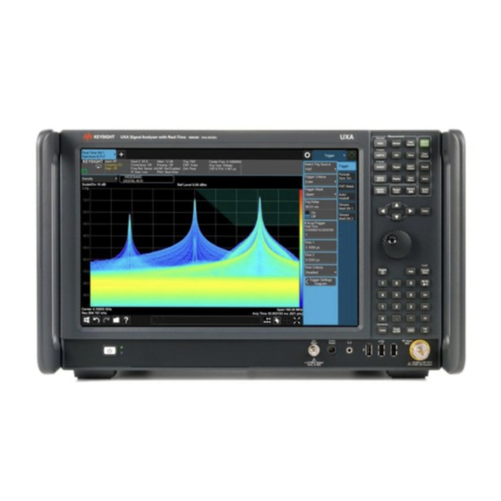
- Page 1 X-Series Signal Analyzer N9042B 4 GHz Analysis Bandwidth Option B14, B16 and B17 INSTALLATION NOTE...
- Page 2 The information contained in this document is subject to change without notice. Keysight Technologies makes no warranty of any kind with regard to this material, including but not limited to, the implied warranties of merchantability and fitness for a particular purpose.
- Page 3 Option B14, B16 and B17 – 4 GHz Analysis Bandwidth Option B14, B16 and B17 – 4 GHz Analysis Bandwidth Products Affected: UXA N9042B To Be Performed By: (X) Keysight Service Center ( ) Advanced User ( ) User Estimated Installation Time: 3.0 Hours Estimated Adjustment Time: 2.0 Hours...
-
Page 4: Table Of Contents
What You Will Find in this Document What You Will Find in this Document Information......................page 5 Upgrade Contents ......................page 7 Tools Required ......................page 9 Initial Instrument Functionality Check ................ page 9 License Key Retrieval and Installation ................ page 9 A23 IF Mux Revision Check.................. -
Page 5: Esd Information
ESD Information ESD Information Protection from Electrostatic Discharge Electrostatic discharge (ESD) can damage or destroy electronic components. All work on electronic assemblies should be performed at a static-safe workstation. Figure 1 shows an example of a static-safe workstation using two types of ESD protection: —... - Page 6 ESD Information Handling of Electronic Components and ESD The possibility of unseen damage caused by ESD is present whenever components are transported, stored, or used. The risk of ESD damage can be greatly reduced by paying close attention to how all components are handled.
-
Page 7: Upgrade Contents
Upgrade Contents Upgrade Contents Table 1 Upgrade Contents Part Reference Description Quantity Number Designator 0515-0372 Screw-Machine w/Crest-Cup-Washer Panhead Torx-T10 M3X0.5 8mm-LG 0515-1946 Screw-Machine w/Patch Lock Flathead Torx-T10 M3X0.5 6mm-LG 0515-1992 Screw-Machine w/Crest-Cup-Washer Panhead Torx-T8 M2.5X0.45 20mm-LG 0515-2332 Screw-Machine w/Patch Lock Panhead Torx-T10 M3X0.5 6mm-LG 1005-1377 Optical Cable Panel Mount Adapter 1400-0053... - Page 8 Upgrade Contents Table 1 Upgrade Contents Part Reference Description Quantity Number Designator N9041-60185 Cable, Wire Harness, A18 MIMM Carrier J17 to SW5 Direct Digitization Switch 9030-0000 License Entitlement Certificate N9041-90010 Installation Note This upgrade kits includes enough parts so that all versions of the N9042B instrument can be successfully upgraded with the 4 GHz Analysis Bandwidth option.
-
Page 9: Tools Required
Tools Required Tools Required — TORX Driver, T-8 — TORX Driver, T-10 — TORX Driver, T-20 — Multi-Bit Torque Driver — 5/8" Nut Driver — 5/16" Wrench — Modified 5/16” Socket (N5191-20299) Initial Instrument Functionality Check Power on the instrument and allow it to complete its boot up process. Verify that there are no instrument messages that would indicate that there is an issue with either the instrument hardware or software. -
Page 10: A23 If Mux Revision Check
A23 IF Mux Revision Check A23 IF Mux Revision Check While the instrument is still powered on check to see what version of the A23 IF Mux is installed in the instrument by pressing System, Show Hardware. Find the IF Mux-10GHz entry, as seen in Figure 2, and record the Part # below. -
Page 11: Upgrade Instructions
Upgrade Instructions Upgrade Instructions Hardware Disassembly The following is a list of the sheet metal parts and assemblies that need to be removed before installing this upgrade. If instructions are needed for any of these, see Chapter 20, Assembly Replacement Procedures in the N9042B Service Guide. Assembly and Sheet Metal Removal 1. - Page 12 Upgrade Instructions 3. Referring to Figure 4, remove the Chassis Rear Brace. Figure 4 Chassis Rear Brace Removal Additional Part Removal 4. Referring to Figure 5, remove W43 from the A11 Band Switch P1. Figure 5 W43 Removal – A11 Band Switch P1 Installation Note N9042-90010...
- Page 13 Upgrade Instructions 5. Referring to Figure 6, remove W43 from the A13 Narrowband Downconverter J2 and carefully remove the cable from the instrument. This cable will not be reused. Figure 6 W43 Removal - A13 Narrowband Downconverter End 6. Referring to Figure 7, remove W107 from the A16 Reference J711 and from the A2 25 MHz Analog IF J300.
- Page 14 Upgrade Instructions 7. Referring to Figure 8, remove the three 50 ohm terminations connected to the A23 IF Mux. The terminations will not be reused. Figure 8 A23 IF Mux 50 Ohm Terminations Removal Installation Note N9042-90010...
- Page 15 Upgrade Instructions A21 Wideband Digital IF Removal 8. Referring to Figure 9, disconnect the four coax cables from the A21 Wideband Digital IF. Figure 9 A21 Wideband Digital IF Coax Cables Removal 9. Referring to Figure 10, use the two board extractors (1) to carefully remove the A21 Wideband Digital IF (2) from the instrument.
-
Page 16: Odi Cable Installation
Upgrade Instructions ODI Cable Installation The new parts supplied with this upgrade that will be needed in this section are listed in Table Table 2 ODI Cable Installation Parts Description Part Number ODI Heatsink N9041-20154 ODI Cable, Receiver 8121-3405 Panhead Screws (x4) 0515-2332 ODI Heatsink Removal 1. - Page 17 Upgrade Instructions ODI Cable Installation The connector of the ODI cable provided in this kit with the blue tab on it needs to be installed on the A21 Wideband Digital IF assembly. These types of connectors can either have a blue tab or an orange tab.
- Page 18 Upgrade Instructions 5. Lower the cable and connector onto the connector on the A21 Wideband Digital IF, as seen in Figure Figure 16 Lower Cable Connector onto Board Connector 6. Slide the connector to engage the forward connector, as seen in Figure Figure 17 Slide Connector into Place...
- Page 19 Upgrade Instructions 8. Properly route the ODI cable so that it does not get pinched when the new heatsink is put into place, as seen in Figure 9. Referring to Figure 19, install the new ODI heatsink (3) with four new panhead screws (1) (0515-2332) and the one original long panhead screw (2) onto the A21 Wideband Digital IF assembly (4).
-
Page 20: Reinstall A21 Wideband Digital If
Upgrade Instructions Reinstall A21 Wideband Digital IF 1. Referring to Figure 20, reinstall the A21 Wideband Digital IF, carefully moving any cables out of the way, especially the ODI cable (2) that was just installed. Use the card extractors (1) to lock the assembly into place. -
Page 21: A22 Ultra-Wideband Analog If Installation
Upgrade Instructions A22 Ultra-Wideband Analog IF Installation The new parts supplied with this upgrade that will be needed in this section are listed in Table Table 4 A22 Ultra-Wideband Installation Parts Reference Designator Part Number N9040-65170 N9041-20131 W107 8121-1401 W112 8121-0152 W113 8121-2607... - Page 22 Upgrade Instructions 2. Referring to Figure 22, install the new W114 coax cable (8121-2290) from the A2 25 MHz Analog IF to the location shown in preparation for the new A22 Ultra-Wideband Analog IF installation (shown in blue). 3. In preparation for installing the new A22 Ultra-Wideband Analog IF, gather the three twinax cables (8121-3407) and install them onto the new A22 assembly (N9040-65170), as seen in Figure Figure 23...
- Page 23 Upgrade Instructions Figure 25 A22 Ultra-Wideband Analog IF Installation 5. Attach the three twinax cable to the A21 Wideband Digital IF, observing how two of the cables cross, as seen in Figure Figure 26 Twinax Cable Connections 6. Referring to Figure 22 Figure 27, connect the two cables that were installed in steps 1 and...
- Page 24 Upgrade Instructions Table 5 A22 Ultra-Wideband Analog IF Reference Connections A22 Port To/From Cable From A16 Reference J711 W107 To A2 25 MHz Analog IF J300 W114 7. Referring to Figure 28, install the new W112 coax cable (8121-0152) from the A21 Wideband Digital IF J2 to the new A22 Ultra-Wideband Analog IF J14 (shown in yellow).
- Page 25 Upgrade Instructions 10.Use the procedure that follows for the instrument configuration that was determined earlier in “A23 IF Mux Revision Check” section in this installation note. Configuration A The new parts supplied with this upgrade that will be needed for this configuration are listed in Table Table 6 A22 Ultra-Wideband Analog IF Input Parts - Configuration A...
- Page 26 Upgrade Instructions Configuration B a. Install the new W55 (N9041-20132) between the A22 Ultra-Wideband Analog IF J9 and the A23 IF Mux J25, as seen in Figure 31. Torque all connections to 10 in-lbs. Figure 31 A22 Ultra-Wideband Analog IF Input Connection - Configuration B Installation Note N9042-90010...
-
Page 27: Reinstall Chassis Rear Brace
Upgrade Instructions Reinstall Chassis Rear Brace The new parts supplied with this upgrade that will be needed in this section are listed in Table Table 7 Chassis Rear Brace Parts Description Part Number Panhead Screws (x2) 0515-0372 Flathead Screws (x5) 0515-1946 Optical Cable Panel Mount Adapter 1005-1377... - Page 28 Upgrade Instructions Figure 33 Reinstall Chassis Rear Brace Then attaching the chassis rear brace be sure that none of the coax cables are being pinched between the connectors of other cables and the brace. 4. Secure the chassis rear brace to the instrument with the four panhead screws (2) and the three new flathead screws (3) (0515-1946).
-
Page 29: Sw5 Direct Digitization Switch Installation
Upgrade Instructions SW5 Direct Digitization Switch Installation The new parts supplied with this upgrade that will be needed in this section are listed in Table Table 8 SW5 Direct Digitization Switch Parts Reference Designator Part Number Panhead Screws (x2) 0515-1992 Direct Digitization Switch N1810-60102 Wire Harness, SW5 Direct Digitization Switch... - Page 30 Upgrade Instructions 3. Referring to Figure 35, attach the new wire harness W24 (N9041-60185) from the A18 MMM Carrier J17 to the wire harness attached to SW5. Figure 35 W24 Installation Installation Note N9042-90010...
- Page 31 Upgrade Instructions 4. Referring to Figure 36, install the new semi-rigid cable W43B (N9041-20166) and attach one end to the SW5 port 1 as shown. Figure 36 W43B Installation - SW5 Direct Digitization Switch End 5. Referring to Figure 37, connect the other end of W43B to the A13 Narrowband Downconverter J2.
- Page 32 Upgrade Instructions 6. Referring to Figure 38, install the new semi-rigid cable W43A (N9041-20165) between the center port of SW5 and the A11 Band Switch port 1 as shown. Torque both ends of the cable to 10 in-lbs. Figure 38 W43A Installation 7.
-
Page 33: Instrument Button Up
Upgrade Instructions Instrument Button Up Cable Restraints Replace any of the nylon cable ties that were cut during this upgrade with the ones supplied, to secure the cables in the instrument. Assembly and Sheet Metal Installation The following is a list of the sheet metal parts and assemblies that need to be reinstalled. If instructions are needed for any of these, see Chapter 20, Assembly Replacement Procedures in the N9042B Service Guide. -
Page 34: Fpga Synchronization
This can be done by using one of the following processes: 1. Install the latest version of the instrument software available by downloading it and the instructions from: https://www.keysight.com/find/n9042b_software 2. Run the following FPGA synchronization process. FPGA Synchronization Once the FPGA programming process has started it MUST NOT be interrupted for any reason. -
Page 35: Adjustments And Performance Verification
Adjustments and Performance Verification Adjustments and Performance Verification Manual Procedures Required Front Panel Key Test Front Panel Display Test Front Panel Touch Test Automated Utilities Required None Automated Adjustments Required All Frequency Response Adjustments All IF Frequency Response Adjustments Automated Performance Verification Testing Required All performance verification tests 1. - Page 36 This information is subject to change without notice. © Keysight Technologies 2023 Edition 1, February 2023 N9042-90010 www.keysight.com...
Need help?
Do you have a question about the X Series and is the answer not in the manual?
Questions and answers