GE MiCOM P40 Agile Technical Manual
Single breaker current differential (with distance)
Hide thumbs
Also See for MiCOM P40 Agile:
- Technical manual (962 pages) ,
- Technical manual (623 pages) ,
- Technical manual (458 pages)
Table of Contents
Advertisement
Quick Links
Download this manual
See also:
Technical Manual
Advertisement
Chapters
Table of Contents
Troubleshooting

Related Manuals for GE MiCOM P40 Agile


Summary of Contents for GE MiCOM P40 Agile
- Page 1 GE Energy Connections Grid Solutions MiCOM P40 Agile P543i/P545i Technical Manual Single Breaker Current Differential (with Distance) Hardware Version: M Software Version: 85 Publication Reference: P54x1i-TM-EN-1...
-
Page 3: Table Of Contents
Contents Chapter 1 Introduction Chapter Overview Foreword Target Audience Typographical Conventions Nomenclature Compliance Product Scope Product Versions 3.1.1 Ordering Options Features and Functions Current Differential Protection Functions Distance Protection Functions Protection Functions Control Functions Measurement Functions Communication Functions Logic Diagrams Functional Overview Chapter 2 Safety Information... - Page 4 Contents P543i/P545i 4.1.1 Front Panel Compartments 4.1.2 Keypad 4.1.3 Front Serial Port (SK1) 4.1.4 Front Parallel Port (SK2) 4.1.5 Fixed Function LEDs 4.1.6 Function Keys 4.1.7 Programable LEDs Rear Panel Boards and Modules PCBs Subassemblies Main Processor Board Power Supply Board 6.4.1 Watchdog 6.4.2...
- Page 5 P543i/P545i Contents 5.11 Function Key Interface Chapter 5 Configuration Chapter Overview Settings Application Software Using the HMI Panel Navigating the HMI Panel Getting Started Default Display Default Display Navigation Password Entry Processing Alarms and Records Menu Structure Changing the Settings Direct Access (The Hotkey menu) 3.9.1 Setting Group Selection Using Hotkeys...
- Page 6 Contents P543i/P545i 10.4.1 Fifth Harmonic Blocking 10.5 Logic for Feeders with In-Zone Transformers 10.6 Second Harmonic Blocking Logic 10.7 Fifth Harmonic Blocking Logic Current Differential Intertripping Stub Bus Differential Protection Application Notes 13.1 Setting Up the Phase Differential Characteristic 13.2 Sensitivity Under Heavy Loads 13.3 Permissive Intertripping...
- Page 7 P543i/P545i Contents Cross Country Fault Protection Delta Directional Element Delta Directional Principle and Setup Delta Directional Decision Distance Isolated and Compensated Systems Peterson Coil Earthed Systems Earth Fault Distance Protection for Isolated and Compensated Systems 6.2.1 Single-phase to Earth Faults on Isolated or Compensated Systems 6.2.2 Cross-Country Faults on Isolated or Compensated Systems Implementation of Distance Protection for Isolated and Compensated Networks...
- Page 8 Contents P543i/P545i Current Reversal Guard Logic Aided Distance Blocking Schemes Aided Distance Unblocking Schemes Aided Distance Logic Diagrams 4.7.1 Aided Distance Send Logic 4.7.2 Carrier Aided Schemes Receive Logic 4.7.3 Aided Distance Tripping Logic 4.7.4 PUR Aided Tripping logic 4.7.5 POR Aided Tripping logic 4.7.6 Aided Scheme Blocking 1 Tripping logic...
- Page 9 P543i/P545i Contents Trip On Close Schemes Switch On To Fault (SOTF) 4.1.1 Switch Onto Fault Mode 4.1.2 SOTF Tripping 4.1.3 SOTF Tripping with CNV Trip On Reclose (TOR) 4.2.1 Trip On Reclose Mode 4.2.2 TOR Tripping Logic for Appropriate Zones 4.2.3 TOR Tripping Logic with CNV Polarisation during Circuit Engergisation...
- Page 10 Contents P543i/P545i Autoreclose System Map Diagrams Autoreclose Internal Signals Autoreclose DDB Signals Logic Modules Circuit Breaker Status Monitor 5.1.1 CB State Monitor Logic diagram Circuit Breaker Open Logic 5.2.1 Circuit Breaker Open Logic Diagram Circuit Breaker in Service Logic 5.3.1 Circuit Breaker in Service Logic Diagram 5.3.2 Autoreclose OK Logic Diagram...
- Page 11 P543i/P545i Contents 5.22 Monitor Checks for CB Closure 5.22.1 Check Synchronisation Monitor for CB Closure 5.22.2 Voltage Monitor for CB Closure 5.23 Synchronisation Checks for CB Closure 5.23.1 Three-phase Autoreclose System Check Logic Diagram 5.23.2 CB Manual Close System Check Logic Diagram Setting Guidelines De-ionising Time Guidance Dead Timer Setting Guidelines...
- Page 12 Contents P543i/P545i Sensitive Earth Fault Protection Logic Application Notes 5.4.1 Insulated Systems 5.4.2 Setting Guidelines (Insulated Systems) High Impedance REF High Impedance REF Principle Thermal Overload Protection Single Time Constant Characteristic Dual Time Constant Characteristic Thermal Overload Protection Implementation Thermal Overload Protection Logic Application Notes 7.5.1 Setting Guidelines for Dual Time Constant Characteristic...
- Page 13 P543i/P545i Contents Overfrequency Protection 2.2.1 Overfrequency Protection Implementation 2.2.2 Overfrequency Protection logic 2.2.3 Application Notes Independent R.O.C.O.F Protection Indepenent R.O.C.O.F Protection Implementation Independent R.O.C.O.F Protection Logic Chapter 16 Current Transformer Requirements Chapter Overview Recommended CT Classes Current Differential Requirements Distance Protection Requirements Determining Vk for IEEE C-class CT Worked Examples Calculation of Primary X/R ratio...
- Page 14 Contents P543i/P545i Reset Lockout Alarm CB Condition Monitoring Logic Reset Circuit Breaker Lockout 5.7.1 Reset CB Lockout Logic Diagram Application Notes 5.8.1 Setting the Thresholds for the Total Broken Current 5.8.2 Setting the thresholds for the Number of Operations 5.8.3 Setting the thresholds for the Operating Time 5.8.4 Setting the Thresholds for Excesssive Fault Frequency...
- Page 15 P543i/P545i Contents Standard CTS Logic CTS Blocking Application Notes 4.6.1 Setting Guidelines 4.6.2 Differential CTS Setting Guidelines Trip Circuit Supervision Trip Circuit Supervision Scheme 1 5.1.1 Resistor Values 5.1.2 PSL for TCS Scheme 1 Trip Circuit Supervision Scheme 2 5.2.1 Resistor Values 5.2.2 PSL for TCS Scheme 2...
- Page 16 Contents P543i/P545i Chapter Overview Introduction Teleprotection Scheme Principles Direct Tripping Permissive Tripping Implementation Configuration Connecting to Electrical InterMiCOM Short Distance Long Distance Application Notes Chapter 22 Communications Chapter Overview Communication Interfaces Serial Communication EIA(RS)232 Bus EIA(RS)485 Bus 3.2.1 EIA(RS)485 Biasing Requirements K-Bus Standard Ethernet Communication Hot-Standby Ethernet Failover...
- Page 17 P543i/P545i Contents 5.9.9 End of Session 5.10 Switch Manager 5.10.1 Installation 5.10.2 Setup 5.10.3 Network Setup 5.10.4 Bandwidth Used 5.10.5 Reset Counters 5.10.6 Check for Connected Equipment 5.10.7 Mirroring Function 5.10.8 Ports On/Off 5.10.9 VLAN 5.10.10 End of Session Simple Network Management Protocol (SNMP) SNMP Management Information Bases Main Processor MIBS Structure Redundant Ethernet Board MIB Structure...
- Page 18 Contents P543i/P545i 7.4.8 Mapping GOOSE Messages to Virtual Inputs 7.4.9 Ethernet Functionality 7.4.10 IEC 61850 Configuration 7.4.11 IEC 61850 Edition 2 Read Only Mode IEC 60870-5-103 Protocol Blocking Courier Protocol Blocking IEC 61850 Protocol Blocking Read-Only Settings Read-Only DDB Signals Time Synchronisation Demodulated IRIG-B 9.1.1...
- Page 19 P543i/P545i Contents Unpacking the Goods Storing the Goods Dismantling the Goods Mounting the Device Flush Panel Mounting Rack Mounting Cables and Connectors Terminal Blocks Power Supply Connections Earth Connnection Current Transformers Voltage Transformer Connections Watchdog Connections EIA(RS)485 and K-Bus Connections IRIG-B Connection Opto-input Connections 4.10...
- Page 20 Contents P543i/P545i 5.1.4 External Wiring 5.1.5 Watchdog Contacts 5.1.6 Power Supply Product Checks with the IED Energised 5.2.1 Watchdog Contacts 5.2.2 Test LCD 5.2.3 Date and Time 5.2.4 Test LEDs 5.2.5 Test Alarm and Out-of-Service LEDs 5.2.6 Test Trip LED 5.2.7 Test User-programmable LEDs 5.2.8...
- Page 21 P543i/P545i Contents 12.2.4 Zone 3 Reach Check 12.2.5 Zone 4 Reach Check 12.2.6 Zone P Reach Check 12.2.7 Zone Q Reach Check 12.2.8 Resistive Reach 12.2.9 Load Blinder 12.3 Operation and Contact Assignment 12.3.1 Phase A 12.3.2 Phase B 12.3.3 Phase C 12.3.4 Time Delay Settings...
- Page 22 Contents P543i/P545i 19.1.3 Communications using P59x Interface Units 19.2 Remove Remote Loopbacks 19.3 Verify Communication between IEDs End-to-End Scheme Tests 20.1 Aided Scheme 1 20.1.1 Preparation at Remote End 20.1.2 Performing the Test 20.1.3 Channel Check in the Opposite Direction 20.2 Aided Scheme 2 Onload Checks...
- Page 23 P543i/P545i Contents Mal-operation during testing 3.6.1 Failure of Output Contacts 3.6.2 Failure of Opto-inputs 3.6.3 Incorrect Analogue Signals Coprocessor board failures 3.7.1 Signalling failure alarm (on its own) 3.7.2 C diff failure alarm (on its own) 3.7.3 Signalling failure and C diff failure alarms together 3.7.4 Incompatible IED 3.7.5...
- Page 24 Contents P543i/P545i Standard Current Transformer Supervision Differential Current Transformer Supervision CB State and Condition Monitoring PSL Timers Measurements and Recording General Disturbance Records Event, Fault and Maintenance Records Fault Locator Ratings AC Measuring Inputs Current Transformer Inputs Voltage Transformer Inputs Auxiliary Supply Voltage Nominal Burden Power Supply Interruption...
- Page 25 P543i/P545i Contents 12.3 R&TTE Compliance: 2014/53/EU 12.4 UL/CUL Compliance 12.5 ATEX Compliance: 2014/34/EU Appendix A Ordering Options Appendix B Settings and Signals Appendix C Wiring Diagrams P54x1i-TM-EN-1 xxiii...
- Page 26 Contents P543i/P545i xxiv P54x1i-TM-EN-1...
- Page 27 Table of Figures Figure 1: P40L version M85 - version evolution Figure 2: Key to logic diagrams Figure 3: Functional Overview Figure 4: Hardware architecture Figure 5: Coprocessor hardware architecture Figure 6: Exploded view of IED Figure 7: Front panel (60TE) Figure 8: Rear view of populated case Figure 9:...
- Page 28 Table of Figures P543i/P545i Figure 39: CT Compensation Figure 40: The need for zero-sequence current filtering Figure 41: Magnetising inrush phenomenon Figure 42: Typical overflux current waveform Figure 43: Phase Current Differential Protection logic for feeders with in-zone transformers Figure 44: Second Harmonic Blocking logic Figure 45: Fifth Harmonic Blocking logic...
- Page 29 P543i/P545i Table of Figures Figure 78: Biased Neutral Current Detector Characteristic Figure 79: Load Blinder Characteristics Figure 80: Sequence networks connection for an internal A-N fault Figure 81: - DV Forward and Reverse tripping regions Figure 82: Current level (amps) at which transient faults are self-extinguishing Figure 83: Earth fault in Petersen Coil earthed system Figure 84:...
- Page 30 Table of Figures P543i/P545i Figure 117: DEF Directional Signals Figure 118: Aided DEF Send logic Figure 119: Carrier Aided Schemes Receive logic Figure 120: Aided DEF Tripping logic Figure 121: POR Aided Tripping logic Figure 122: Aided Scheme Blocking 1 Tripping logic Figure 123: Aided Scheme Blocking 2 Tripping logic Figure 124:...
- Page 31 P543i/P545i Table of Figures Figure 157: PSB timer setting guidelines Figure 158: Out of Step detection characteristic Figure 159: Out of Step logic diagram Figure 160: OST setting determination for the positive sequence resistive component OST R5 Figure 161: OST R6max determination Figure 162: Example of timer reset due to MOVs operation Figure 163:...
- Page 32 Table of Figures P543i/P545i Figure 197: Autoreclose Shot Counters logic diagram (Module 41) Figure 198: CB Control logic diagram (Module 43) Figure 199: Circuit Breaker Trip Time Monitoring logic diagram (Module 53) Figure 200: AR Lockout Logic Diagram (Module 55) Figure 201: Reset Circuit Breaker Lockout Logic Diagram (Module 57) Figure 202:...
- Page 33 P543i/P545i Table of Figures Figure 237: Underfrequency logic (single stage) Figure 238: Overfrequency logic (single stage) Figure 239: Rate of change of frequency logic (single stage) Figure 240: Fault recorder stop conditions Figure 241: Broken Current Accumulator logic diagram Figure 242: CB Trip Counter logic diagram Figure 243: Operating Time Accumulator...
- Page 34 Table of Figures P543i/P545i Figure 277: IM64 communications mode and IEEE C37.94 alarm signals Figure 278: IM64 two-terminal scheme extended supervision Figure 279: IM64 three-terminal scheme extended supervision Figure 280: Example assignment of InterMiCOM signals within the PSL Figure 281: Direct connection Figure 282: Indirect connection using modems...
- Page 35 P543i/P545i Table of Figures Figure 316: Simulated input behaviour Figure 317: Test example 1 Figure 318: Test example 2 Figure 319: Test example 3 Figure 320: Current Differential Bias Characteristics Figure 321: State impedances Figure 322: Possible terminal block types Figure 323: Front panel assembly P54x1i-TM-EN-1...
- Page 36 Table of Figures P543i/P545i xxxiv P54x1i-TM-EN-1...
-
Page 37: Chapter 1 Introduction
CHAPTER 1 INTRODUCTION... - Page 38 Chapter 1 - Introduction P543i/P545i P54x1i-TM-EN-1...
-
Page 39: Chapter Overview
P543i/P545i Chapter 1 - Introduction CHAPTER OVERVIEW This chapter provides some general information about the technical manual and an introduction to the device(s) described in this technical manual. This chapter contains the following sections: Chapter Overview Foreword Product Scope Features and Functions Logic Diagrams Functional Overview P54x1i-TM-EN-1... -
Page 40: Foreword
Chapter 1 - Introduction P543i/P545i FOREWORD This technical manual provides a functional and technical description of General Electric's P543i/P545i, as well as a comprehensive set of instructions for using the device. The level at which this manual is written assumes that you are already familiar with protection engineering and have experience in this discipline. -
Page 41: Nomenclature
P543i/P545i Chapter 1 - Introduction NOMENCLATURE Due to the technical nature of this manual, many special terms, abbreviations and acronyms are used throughout the manual. Some of these terms are well-known industry-specific terms while others may be special product- specific terms used by General Electric. The first instance of any acronym or term used in a particular chapter is explained. -
Page 42: Product Scope
Chapter 1 - Introduction P543i/P545i PRODUCT SCOPE The P543 and P545 devices have been designed for current differential protection of overhead line and cable applications. Version M85 of P543 and P545 have been designed for both solidly grounded systems and Petersen Coil grounded systems. -
Page 43: Ordering Options
P543i/P545i Chapter 1 - Introduction P445: P46 P54x No Distance : M66 P841A: M66 Special All other products: M76 P443: M78B · Current Diff Starters for P 54x · Other improvements · Zone Q addition · PSB changes · VT input for Vn meas . ·... -
Page 44: Features And Functions
Chapter 1 - Introduction P543i/P545i FEATURES AND FUNCTIONS CURRENT DIFFERENTIAL PROTECTION FUNCTIONS Feature IEC 61850 ANSI Phase segregated current differential protection DifPDIF1 Neutral current differential protection (optional) DifPDIF2 2 and 3 terminal lines/cables Feeders with in-zone transformers Suitable for use with SDH/SONET networks (using P594) GPS time synchronization (optional) DISTANCE PROTECTION FUNCTIONS Feature... -
Page 45: Control Functions
P543i/P545i Chapter 1 - Introduction Feature IEC 61850 ANSI Phase overcurrent , with optional directionality (4 stages) OcpPTOC/RDIR 50/51/67 Earth/Ground overcurrent stages, with optional directionality (4 EfdPTOC/RDIR 50N/51N/ 67N stages) Sensitive earth fault (SEF) (4 stages) SenPTOC/RDIR 50N/51N/67N High impedance restricted earth fault (REF) SenRefPDIF Transient Earth Fault Detection (TEFD) PTEF... -
Page 46: Measurement Functions
Chapter 1 - Introduction P543i/P545i Feature IEC 61850 ANSI Fault locator RFLO MEASUREMENT FUNCTIONS Measurement Function IEC 61850 ANSI Measurement of all instantaneous & integrated values (Exact range of measurements depend on the device model) Disturbance recorder for waveform capture – specified in samples per cycle RDRE Fault Records Maintenance Records Event Records / Event logging... -
Page 47: Logic Diagrams
P543i/P545i Chapter 1 - Introduction LOGIC DIAGRAMS This technical manual contains many logic diagrams, which should help to explain the functionality of the device. Although this manual has been designed to be as specific as possible to the chosen product, it may contain diagrams, which have elements applicable to other products. -
Page 48: Figure 2: Key To Logic Diagrams
Chapter 1 - Introduction P543i/P545i Key: Energising Quantity AND gate & Internal Signal OR gate DDB Signal XOR gate Internal function NOT gate Setting cell Logic 0 Setting value Timer Hardcoded setting Pulse / Latch Measurement Cell SR Latch Internal Calculation SR Latch Reset Dominant Derived setting... -
Page 49: Functional Overview
P543i/P545i Chapter 1 - Introduction FUNCTIONAL OVERVIEW This diagram is applicable to P543 and P545models. BUS 1 2 nd Remote Remote Local Disturbance Fault records comm. port comm. port Communication Record 61850 Measurements Self monitoring 50N/ 50/27 50/51 I/ V 67/46 TEFD* V ref... - Page 50 Chapter 1 - Introduction P543i/P545i P54x1i-TM-EN-1...
-
Page 51: Chapter 2 Safety Information
CHAPTER 2 SAFETY INFORMATION... - Page 52 Chapter 2 - Safety Information P543i/P545i P54x1i-TM-EN-1...
-
Page 53: Chapter Overview
P543i/P545i Chapter 2 - Safety Information CHAPTER OVERVIEW This chapter provides information about the safe handling of the equipment. The equipment must be properly installed and handled in order to maintain it in a safe condition and to keep personnel safe at all times. You must be familiar with information contained in this chapter before unpacking, installing, commissioning, or servicing the equipment. -
Page 54: Health And Safety
Chapter 2 - Safety Information P543i/P545i HEALTH AND SAFETY Personnel associated with the equipment must be familiar with the contents of this Safety Information. When electrical equipment is in operation, dangerous voltages are present in certain parts of the equipment. Improper use of the equipment and failure to observe warning notices will endanger personnel. -
Page 55: Symbols
P543i/P545i Chapter 2 - Safety Information SYMBOLS Throughout this manual you will come across the following symbols. You will also see these symbols on parts of the equipment. Caution: Refer to equipment documentation. Failure to do so could result in damage to the equipment Warning: Risk of electric shock... -
Page 56: Installation, Commissioning And Servicing
Chapter 2 - Safety Information P543i/P545i INSTALLATION, COMMISSIONING AND SERVICING LIFTING HAZARDS Many injuries are caused by: Lifting heavy objects ● Lifting things incorrectly ● ● Pushing or pulling heavy objects Using the same muscles repetitively ● Plan carefully, identify any possible hazards and determine how best to move the product. Look at other ways of moving the load to avoid manual handling. -
Page 57: Ul/Csa/Cul Requirements
P543i/P545i Chapter 2 - Safety Information Caution: NEVER look into optical fibres or optical output connections. Always use optical power meters to determine operation or signal level. Warning: Testing may leave capacitors charged to dangerous voltage levels. Discharge capacitors by rediucing test voltages to zero before disconnecting test leads. Caution: Operate the equipment within the specified electrical and environmental limits. -
Page 58: Equipment Connections
Chapter 2 - Safety Information P543i/P545i Caution: Digital input circuits should be protected by a high rupture capacity NIT or TIA fuse with maximum rating of 16 A. for safety reasons, current transformer circuits must never be fused. Other circuits should be appropriately fused to protect the wire used. Caution: CTs must NOT be fused since open circuiting them may produce lethal hazardous voltages... -
Page 59: Pre-Energisation Checklist
P543i/P545i Chapter 2 - Safety Information Caution: Use a locknut or similar mechanism to ensure the integrity of stud-connected PCTs. Caution: The recommended minimum PCT wire size is 2.5 mm² for countries whose mains supply is 230 V (e.g. Europe) and 3.3 mm² for countries whose mains supply is 110 V (e.g. North America). -
Page 60: Upgrading/Servicing
Chapter 2 - Safety Information P543i/P545i Note: For most Alstom equipment with ring-terminal connections, the threaded terminal block for current transformer termination is automatically shorted if the module is removed. Therefore external shorting of the CTs may not be required. Check the equipment documentation and wiring diagrams first to see if this applies. -
Page 61: Decommissioning And Disposal
P543i/P545i Chapter 2 - Safety Information DECOMMISSIONING AND DISPOSAL Caution: Before decommissioning, completely isolate the equipment power supplies (both poles of any dc supply). The auxiliary supply input may have capacitors in parallel, which may still be charged. To avoid electric shock, discharge the capacitors using the external terminals before decommissioning. -
Page 62: Regulatory Compliance
Chapter 2 - Safety Information P543i/P545i REGULATORY COMPLIANCE Compliance with the European Commission Directive on EMC and LVD is demonstrated using a technical file. EMC COMPLIANCE: 2014/30/EU The product specific Declaration of Conformity (DoC) lists the relevant harmonised standard(s) or conformit assessment used to demonstrate compliance with the EMC directive. - Page 63 P543i/P545i Chapter 2 - Safety Information Where: 'II' Equipment Group: Industrial. '(2)G' High protection equipment category, for control of equipment in gas atmospheres in Zone 1 and 2. This equipment (with parentheses marking around the zone number) is not itself suitable for operation within a potentially explosive atmosphere.
- Page 64 Chapter 2 - Safety Information P543i/P545i P54x1i-TM-EN-1...
-
Page 65: Chapter 3 Hardware Design
CHAPTER 3 HARDWARE DESIGN... - Page 66 Chapter 3 - Hardware Design P543i/P545i P54x1i-TM-EN-1...
-
Page 67: Chapter Overview
P543i/P545i Chapter 3 - Hardware Design CHAPTER OVERVIEW This chapter provides information about the product's hardware design. This chapter contains the following sections: Chapter Overview Hardware Architecture Mechanical Implementation Front Panel Rear Panel Boards and Modules P54x1i-TM-EN-1... -
Page 68: Hardware Architecture
Chapter 3 - Hardware Design P543i/P545i HARDWARE ARCHITECTURE The main components comprising devices based on the Px4x platform are as follows: The housing, consisting of a front panel and connections at the rear ● The Main processor module consisting of the main CPU (Central Processing Unit), memory and an interface ●... -
Page 69: Figure 5: Coprocessor Hardware Architecture
P543i/P545i Chapter 3 - Hardware Design FPGA Comms between main and coprocessor board SRAM Ch1 for current differential input Optional comms interface Ch2 for current differential input Optional coprocessor board V00249 Figure 5: Coprocessor hardware architecture P54x1i-TM-EN-1... -
Page 70: Mechanical Implementation
Chapter 3 - Hardware Design P543i/P545i MECHANICAL IMPLEMENTATION All products based on the Px4x platform have common hardware architecture. The hardware is modular and consists of the following main parts: Case and terminal blocks ● Boards and modules ● Front panel ●... -
Page 71: List Of Boards
P543i/P545i Chapter 3 - Hardware Design Case width (TE) Case width (mm) Case width (inches) 40TE 203.2 60TE 304.8 80TE 406.4 Note: Not all case sizes are available for all models. LIST OF BOARDS The product's hardware consists of several modules drawn from a standard range. The exact specification and number of hardware modules depends on the model number and variant. - Page 72 Chapter 3 - Hardware Design P543i/P545i Coprocessor board with fibre connections for current differential inputs + GPS Coprocessor board with dual fibre inputs + GPS input. P54x1i-TM-EN-1...
-
Page 73: Front Panel
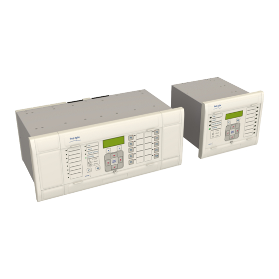
P543i/P545i Chapter 3 - Hardware Design FRONT PANEL FRONT PANEL Depending on the exact model and chosen options, the product will be housed in either a 40TE, 60TE or 80TE case. By way of example, the following diagram shows the front panel of a typical 60TE unit. The front panels of the products based on 40TE and 80TE cases have a lot of commonality and differ only in the number of hotkeys and user-programmable LEDs. -
Page 74: Keypad
Chapter 3 - Hardware Design P543i/P545i The bottom compartment contains: A compartment for a 1/2 AA size backup battery (used to back up the real time clock and event, fault, and ● disturbance records). A 9-pin female D-type front port for an EIA(RS)232 serial connection to a PC. ●... -
Page 75: Front Parallel Port (Sk2)
P543i/P545i Chapter 3 - Hardware Design Note: The front serial port does not support automatic extraction of event and disturbance records, although this data can be accessed manually. 4.1.3.1 FRONT SERIAL PORT (SK1) CONNECTIONS The port pin-out follows the standard for Data Communication Equipment (DCE) device with the following pin connections on a 9-pin connector. -
Page 76: Programable Leds
Chapter 3 - Hardware Design P543i/P545i 4.1.7 PROGRAMABLE LEDS The device has a number of programmable LEDs, which can be associated with PSL-generated signals. The programmable LEDs for most models are tri-colour and can be set to RED, YELLOW or GREEN. However the programmable LEDs for some models are single-colour (red) only. -
Page 77: Rear Panel
P543i/P545i Chapter 3 - Hardware Design REAR PANEL The MiCOM Px40 series uses a modular construction. Most of the internal workings are on boards and modules which fit into slots. Some of the boards plug into terminal blocks, which are bolted onto the rear of the unit. However, some boards such as the communications boards have their own connectors. -
Page 78: Figure 9: Terminal Block Types
Chapter 3 - Hardware Design P543i/P545i Figure 9: Terminal block types Note: Not all products use all types of terminal blocks. The product described in this manual may use one or more of the above types. P54x1i-TM-EN-1... -
Page 79: Boards And Modules
P543i/P545i Chapter 3 - Hardware Design BOARDS AND MODULES Each product comprises a selection of PCBs (Printed Circuit Boards) and subassemblies, depending on the chosen configuration. PCBS A PCB typically consists of the components, a front connector for connecting into the main system parallel bus via a ribbon cable, and an interface to the rear. -
Page 80: Main Processor Board
Chapter 3 - Hardware Design P543i/P545i The products in the Px40 series typically contain two sub-assemblies: The power supply assembly comprising: ● ○ A power supply board An output relay board ○ The input module comprising: ● One or more transformer boards, which contains the voltage and current transformers (partially or ○... -
Page 81: Power Supply Board
P543i/P545i Chapter 3 - Hardware Design POWER SUPPLY BOARD Figure 12: Power supply board The power supply board provides power to the unit. One of three different configurations of the power supply board can be fitted to the unit. This is specified at the time of order and depends on the magnitude of the supply voltage that will be connected to it. -
Page 82: Figure 13: Power Supply Assembly
Chapter 3 - Hardware Design P543i/P545i Figure 13: Power supply assembly The power supply outputs are used to provide isolated power supply rails to the various modules within the unit. Three voltage levels are used by the unit’s modules: 5.1 V for all of the digital circuits ●... -
Page 83: Watchdog
P543i/P545i Chapter 3 - Hardware Design Figure 14: Power supply terminals 6.4.1 WATCHDOG The Watchdog contacts are also hosted on the power supply board. The Watchdog facility provides two output relay contacts, one normally open and one normally closed. These are used to indicate the health of the device and are driven by the main processor board, which continually monitors the hardware and software when the device is in service. -
Page 84: Rear Serial Port
Chapter 3 - Hardware Design P543i/P545i Figure 15: Watchdog contact terminals 6.4.2 REAR SERIAL PORT The rear serial port (RP1) is housed on the power supply board. This is a three-terminal EIA(RS)485 serial communications port and is intended for use with a permanently wired connection to a remote control centre for SCADA communication. -
Page 85: Input Module - 1 Transformer Board
P543i/P545i Chapter 3 - Hardware Design Figure 16: Rear serial port terminals An additional serial port with D-type presentation is available as an optional board, if required. INPUT MODULE - 1 TRANSFORMER BOARD Figure 17: Input module - 1 transformer board The input module consists of the main input board coupled together with an instrument transformer board. -
Page 86: Input Module Circuit Description
Chapter 3 - Hardware Design P543i/P545i 6.5.1 INPUT MODULE CIRCUIT DESCRIPTION 8 digital inputs Optical Optical Isolator Isolator Noise Noise filter filter Parallel Bus Buffer Transformer board Serial Link Serial A/D Converter interface V00239 Figure 18: Input module schematic A/D Conversion The differential analogue inputs from the CT and VT transformers are presented to the main input board as shown. -
Page 87: Transformer Board
P543i/P545i Chapter 3 - Hardware Design The opto-isolated logic inputs can be configured for the nominal battery voltage of the circuit for which they are a part, allowing different voltages for different circuits such as signalling and tripping. Note: The opto-input circuitry can be provided without the A/D circuitry as a separate board, which can provide supplementary opto-inputs. -
Page 88: Input Board
Chapter 3 - Hardware Design P543i/P545i 6.5.3 INPUT BOARD Figure 20: Input board The input board is used to convert the analogue signals delivered by the current and voltage transformers into digital quantities used by the IED. This input board also has on-board opto-input circuitry, providing eight optically- isolated digital inputs and associated noise filtering and buffering. -
Page 89: Standard Output Relay Board
P543i/P545i Chapter 3 - Hardware Design Terminal Number Opto-input Terminal 17 Common Terminal 18 Common STANDARD OUTPUT RELAY BOARD Figure 21: Standard output relay board - 8 contacts This output relay board has 8 relays with 6 Normally Open contacts and 2 Changeover contacts. The output relay board is provided together with the power supply board as a complete assembly, or independently for the purposes of relay output expansion. -
Page 90: Irig-B Board
Chapter 3 - Hardware Design P543i/P545i Terminal Number Output Relay Terminal 11 Relay 6 NO Terminal 12 Relay 6 NO Terminal 13 Relay 7 changeover Terminal 14 Relay 7 changeover Terminal 15 Relay 7 common Terminal 16 Relay 8 changeover Terminal 17 Relay 8 changeover Terminal 18... -
Page 91: Fibre Optic Board
P543i/P545i Chapter 3 - Hardware Design FIBRE OPTIC BOARD Figure 23: Fibre optic board This board provides an interface for communicating with a master station. This communication link can use all compatible protocols (Courier, IEC 60870-5-103, MODBUS and DNP 3.0). It is a fibre-optic alternative to the metallic RS485 port presented on the power supply terminal block. -
Page 92: Rear Communication Board
Chapter 3 - Hardware Design P543i/P545i REAR COMMUNICATION BOARD Figure 24: Rear communication board The optional communications board containing the secondary communication ports provide two serial interfaces presented on 9 pin D-type connectors. These interfaces are known as SK4 and SK5. Both connectors are female connectors, but are configured as DTE ports. - Page 93 P543i/P545i Chapter 3 - Hardware Design This is a communications board that provides a standard 100-Base Ethernet interface. This board supports one electrical copper connection and one fibre-pair connection. There are several variants for this board as follows: 100 Mbps Ethernet board ●...
-
Page 94: Redundant Ethernet Board
Chapter 3 - Hardware Design P543i/P545i 6.11 REDUNDANT ETHERNET BOARD IRIG-B Link Fail Pin3 connector Pin 2 Pin 1 Link channel B Link channel A (green LED) (green LED) Activity channel Activity channel B A (yellow LED) (yellow LED) V01009 Figure 26: Redundant Ethernet board This board provides dual redundant Ethernet (supported by two fibre pairs) together with an IRIG-B interface for timing. - Page 95 P543i/P545i Chapter 3 - Hardware Design Link Fail Connector (Ethernet Board Watchdog Relay) Closed Open Link fail Channel 1 (A) Link ok Channel 1 (A) Link fail Channel 2 (B) Link ok Channel 2 (B) LEDs Function Flashing Green Link Link ok Link broken Yellow...
-
Page 96: Coprocessor Board
Chapter 3 - Hardware Design P543i/P545i 6.12 COPROCESSOR BOARD Figure 27: Fully populated Coprocessor board Note: The above figure shows a coprocessor complete with GPS input and 2 fibre-optic serial data interfaces, and is not necessarily representative of the product and model described in this manual. These interfaces will not be present on boards that do not require them. - Page 97 P543i/P545i Chapter 3 - Hardware Design If, for example, Device A is transmitting to Device B information about the value of its measured current, the information Device A is receiving from Device B about the current measured at the same time, may reach device B at a different time.
- Page 98 Chapter 3 - Hardware Design P543i/P545i P54x1i-TM-EN-1...
-
Page 99: Chapter 4 Software Design
CHAPTER 4 SOFTWARE DESIGN... - Page 100 Chapter 4 - Software Design P543i/P545i P54x1i-TM-EN-1...
-
Page 101: Chapter Overview
P543i/P545i Chapter 4 - Software Design CHAPTER OVERVIEW This chapter describes the software design of the IED. This chapter contains the following sections: Chapter Overview Sofware Design Overview System Level Software Platform Software Protection and Control Functions P54x1i-TM-EN-1... -
Page 102: Sofware Design Overview
Chapter 4 - Software Design P543i/P545i SOFWARE DESIGN OVERVIEW The device software can be conceptually categorized into several elements as follows: The system level software ● The platform software ● ● The protection and control software These elements are not distinguishable to the user, and the distinction is made purely for the purposes of explanation. -
Page 103: System Level Software
P543i/P545i Chapter 4 - Software Design SYSTEM LEVEL SOFTWARE REAL TIME OPERATING SYSTEM The real-time operating system is used to schedule the processing of the various tasks. This ensures that they are processed in the time available and in the desired order of priority. The operating system also plays a part in controlling the communication between the software tasks, through the use of operating system messages. -
Page 104: System Level Software Initialisation
Chapter 4 - Software Design P543i/P545i 3.4.2 SYSTEM LEVEL SOFTWARE INITIALISATION The initialization process initializes the processor registers and interrupts, starts the watchdog timers (used by the hardware to determine whether the software is still running), starts the real-time operating system and creates and starts the supervisor task. - Page 105 P543i/P545i Chapter 4 - Software Design If the problem is with the battery status or the IRIG-B board, the device continues in operation. For problems detected in any other area, the device initiates a shutdown and re-boot, resulting in a period of up to 10 seconds when the functionality is unavailable.
-
Page 106: Platform Software
Chapter 4 - Software Design P543i/P545i PLATFORM SOFTWARE The platform software has three main functions: To control the logging of records generated by the protection software, including alarms, events, faults, and ● maintenance records To store and maintain a database of all of the settings in non-volatile memory ●... -
Page 107: Protection And Control Functions
P543i/P545i Chapter 4 - Software Design PROTECTION AND CONTROL FUNCTIONS The protection and control software processes all of the protection elements and measurement functions. To achieve this it has to communicate with the system services software, the platform software as well as organise its own operations. -
Page 108: Distance Protection
Chapter 4 - Software Design P543i/P545i board and converts these to 8 samples per cycle based on the nominal frequency. The coprocessor calculates the Fourier transform of the fixed rate samples after every sample, using a one-cycle window. This generates current measurements eight times per cycle which are used for the differential protection algorithm. -
Page 109: Programmable Scheme Logic
P543i/P545i Chapter 4 - Software Design The Fourier function acts as a filter, with zero gain at DC and unity gain at the fundamental, but with good harmonic rejection for all harmonic frequencies up to the nyquist frequency. Frequencies beyond this nyquist frequency are known as alias frequencies, which are introduced when the sampling frequency becomes less than twice the frequency component being sampled. -
Page 110: Event Recording
Chapter 4 - Software Design P543i/P545i EVENT RECORDING A change in any digital input signal or protection element output signal is used to indicate that an event has taken place. When this happens, the protection and control task sends a message to the supervisor task to indicate that an event is available to be processed and writes the event data to a fast buffer controlled by the supervisor task. -
Page 111: Chapter 5 Configuration
CHAPTER 5 CONFIGURATION... - Page 112 Chapter 5 - Configuration P543i/P545i P54x1i-TM-EN-1...
-
Page 113: Chapter Overview
P543i/P545i Chapter 5 - Configuration CHAPTER OVERVIEW Each product has different configuration parameters according to the functions it has been designed to perform. There is, however, a common methodology used across the entire product series to set these parameters. Some of the communications setup can only be carried out using the HMI, and cannot be carried out using settings applications software. -
Page 114: Settings Application Software
Chapter 5 - Configuration P543i/P545i SETTINGS APPLICATION SOFTWARE To configure this device you will need to use the Settings Application Software. The settings application software used in this range of IEDs is called MiCOM S1 Agile. It is a collection of software tools, which is used for setting up and managing the IEDs. -
Page 115: Using The Hmi Panel
P543i/P545i Chapter 5 - Configuration USING THE HMI PANEL Using the HMI, you can: Display and modify settings ● View the digital I/O signal status ● ● Display measurements Display fault records ● Reset fault and alarm indications ● The keypad provides full access to the device functionality using a range of menu options. The information is displayed on the LCD. -
Page 116: Figure 31: Navigating The Hmi
Chapter 5 - Configuration P543i/P545i Note: As the LCD display has a resolution of 16 characters by 3 lines, some of the information is in a condensed mnemonic form. NAVIGATING THE HMI PANEL The cursor keys are used to navigate the menus. These keys have an auto-repeat function if held down continuously. -
Page 117: Default Display
P543i/P545i Chapter 5 - Configuration If there are alarms present, the yellow Alarms LED will be flashing and the menu display will read as follows: Alarms / Faults Present HOTKEY Even though the device itself should be in full working order when you first start it, an alarm could still be present, for example, if there is no network connection for a device fitted with a network card. -
Page 118: Figure 32: Default Display Navigation
Chapter 5 - Configuration P543i/P545i Plant reference (user-defined) For example: Plant Reference MiCOM HOTKEY Access Level For example: Access Level HOTKEY In addition to the above, there are also displays for the system voltages, currents, power and frequency etc., depending on the device model. DEFAULT DISPLAY NAVIGATION The following diagram is an example of the default display navigation. -
Page 119: Password Entry
P543i/P545i Chapter 5 - Configuration If the device is cyber-secure but is not yet configured for NERC compliance (see Cyber-security chapter), a warning will appear when moving from the "NERC compliant" banner. The warning message is as follows: DISPLAY NOT NERC COMPLIANT. -
Page 120: Menu Structure
Chapter 5 - Configuration P543i/P545i Press Clear To Reset Alarms To clear all alarm messages, press the Clear key. To return to the display showing alarms or faults present, and leave the alarms uncleared, press the Read key. Depending on the password configuration settings, you may need to enter a password before the alarm messages can be cleared. -
Page 121: Changing The Settings
P543i/P545i Chapter 5 - Configuration Setting Column Description Sys Fn Links (Row 03) Third setting within first column … … … VIEW RECORDS Second Column definition Select Event [0...n] First setting within second column Menu Cell Ref Second setting within second column Time &... -
Page 122: Direct Access (The Hotkey Menu)
Chapter 5 - Configuration P543i/P545i Note: For the protection group and disturbance recorder settings, if the menu time-out occurs before the changes have been confirmed, the setting values are discarded. Control and support settings, howeverr, are updated immediately after they are entered, without the Update settings? prompt. -
Page 123: Circuit Breaker Control
P543i/P545i Chapter 5 - Configuration To access the hotkey menu from the default display, you press the key directly below the HOTKEY text on the LCD. The following screen will appear. ¬User32 STG GP® HOTKEY MENU EXIT Press the right cursor key twice to get to the first control input, or the left cursor key to get to the last control input. ¬STP GP User02®... - Page 124 Chapter 5 - Configuration P543i/P545i The first cell down in the FUNCTION KEYS column is the Fn Key Status cell. This contains a binary string, which represents the function key commands. Their status can be read from this binary string. FUNCTION KEYS Fn Key Status 0000000000...
-
Page 125: Figure 33: Circuit Breaker Trip Conversion Logic Diagram (Module 63)
P543i/P545i Chapter 5 - Configuration LINE PARAMETERS This product requires information about the circuit to which it is applied. This includes line impedance, residual compensation, and phase rotation sequence. For this reason circuit parameter information must be input using the LINE PARAMETERS settings. These LINE PARAMETERS settings are used by protection elements as well as by the fault locator. -
Page 126: Residual Compensation
Chapter 5 - Configuration P543i/P545i RESIDUAL COMPENSATION To improve accuracy of impedance measuring elements such as those used in distance protection and fault locators, the total loop impedance calculation Z can be calibrated by the positive sequence impedance between the relaying point and the fault (Z ) using the following equation: ⋅... - Page 127 P543i/P545i Chapter 5 - Configuration is the residual current of the parallel line (measured) ● ● is the residual compensation coefficient is the mutual compensation coefficient ● In the above equation: − where: is the total zero sequence impedance of the line (a complex value) ●...
-
Page 128: Date And Time Configuration
Chapter 5 - Configuration P543i/P545i DATE AND TIME CONFIGURATION The date and time setting will normally be updated automatically by the chosen UTC (Universal Time Co- ordination) time synchronisation mechanism when the device is in service. You can also set the date and time manually using the Date/Time cell in the DATE AND TIME column. -
Page 129: Without A Timing Source Signal
P543i/P545i Chapter 5 - Configuration Ensure that the IED is receiving valid time synchronisation messages by checking that the PTP Status cell reads Valid Master. Check that Act. Time Source cell reads PTP. This indicates that the IED is using PTP as the source for its time. -
Page 130: Daylight Saving Time Compensation
Chapter 5 - Configuration P543i/P545i DAYLIGHT SAVING TIME COMPENSATION It is possible to compensate for Daylight Saving time using the following settings DST Enable ● ● DST Offset DST Start ● ● DST Start Day DST Start Month ● DST Start Mins ●... -
Page 131: Settings Group Selection
P543i/P545i Chapter 5 - Configuration SETTINGS GROUP SELECTION You can select the setting group using opto inputs, a menu selection, and for some models the hotkey menu or function keys. You choose which method using the Setting Group setting in the CONFIGURATION column. There are two possibilities;... - Page 132 Chapter 5 - Configuration P543i/P545i P54x1i-TM-EN-1...
-
Page 133: Chapter 6 Current Differential Protection
CHAPTER 6 CURRENT DIFFERENTIAL PROTECTION... - Page 134 Chapter 6 - Current Differential Protection P543i/P545i P54x1i-TM-EN-1...
-
Page 135: Chapter Overview
P543i/P545i Chapter 6 - Current Differential Protection CHAPTER OVERVIEW This product provides biased, phase-segregated, numerical Current Differential protection. This chapter introduces the principles and theory behind Current Differential protection and describes how they are implemented in this product. Guidance for applying this protection is also provided. The current differential protection is enabled by default, but it can be disabled if you don’t want to use it. -
Page 136: Current Differential Protection Principle
Chapter 6 - Current Differential Protection P543i/P545i CURRENT DIFFERENTIAL PROTECTION PRINCIPLE Current differential protection is based on Kirchoff’s Law. It generally uses the Merz-Price principle in which the sum of the currents entering the protected zone should equal the sum of the currents leaving the protected zone. A difference between these currents is known as differential current. - Page 137 P543i/P545i Chapter 6 - Current Differential Protection applications use three current values (one from each terminal) for the evaluation of the Bias and Differential currents. Line differential protection requires the comparison of power system quantities taken at the different line terminals.
-
Page 138: Figure 34: Ping-Pong Measurement For Alignment Of Current Signals
Chapter 6 - Current Differential Protection P543i/P545i SYNCHRONISATION OF CURRENT SIGNALS To ensure accuracy of the calculation of the differential current, the locally derived current values and the values derived from inputs at remote terminals must be aligned to a common time reference before the differential calculations are made. -
Page 139: Gps Synchronisation
P543i/P545i Chapter 6 - Current Differential Protection At time tA1, End A sends a data message to End B. The message contains a time tag, tA1, plus other timing, control, and status information as well as the calculated current values. The message arrives at End B after a channel after a propogation delay time tp1. -
Page 140: Figure 35: Asymmetric Propogation Delay Times
Chapter 6 - Current Differential Protection P543i/P545i tp 1 tB3* tp 2 Relay A Relay B E02607 Figure 35: Asymmetric propogation delay times The GPS synchronised values at terminal A (tA1, etc.) can be individually compared with those at terminal B (tB1, etc.) to derive the bias and differential currents. -
Page 141: Figure 36: Dual Slope Current Differential Bias Characteristic
P543i/P545i Chapter 6 - Current Differential Protection PHASE CURRENT DIFFERENTIAL PROTECTION By appropriate model selection, current differential protection can be provided for two-terminal or three-terminal feeders. Products that have two protection communications channels fitted can be applied to the protection of three-terminal applications. -
Page 142: Phase Current Differential Tripping Criteria
Chapter 6 - Current Differential Protection P543i/P545i PHASE CURRENT DIFFERENTIAL TRIPPING CRITERIA The phase current differential characteristic is defined by four settings: Phase Is1: The basic differential current setting which determines the minimum pick-up level of the ● protection. Phase k1: The lower percentage bias setting used when the bias current is below the Phase Is2 setting. This ●... -
Page 143: Figure 37: Phase Current Differential Protection Logic
P543i/P545i Chapter 6 - Current Differential Protection PHASE CURRENT DIFFERENTIAL PROTECTION LOGIC Permit Cdiff Diff Trip IDiff>Start A & Phase A Operate threshold & Diff Trip A reached Send Diff Intertrip A IDiff>Start B & Phase B Operate threshold & Diff Trip B reached Send Diff Intertrip B... -
Page 144: Neutral Current Differential Protection
Chapter 6 - Current Differential Protection P543i/P545i NEUTRAL CURRENT DIFFERENTIAL PROTECTION In products that feature distance back-up protection, Neutral Current Differential protection is provided to clear high-resistive earth faults which may be below the Phase Current Differential sensitivity limit. If you wish to use the Neutral Current Differential protection you must enable it using the In Diff setting under the NEUTRAL DIFF subheading of the CURRENT DIFF column. -
Page 145: Three-Terminal Schemes
P543i/P545i Chapter 6 - Current Differential Protection THREE-TERMINAL SCHEMES Products that have two protection communications channels fitted can be applied to the protection of three- terminal applications. By appropriate model selection, current differential protection can be provided for two-terminal or three-terminal feeders. -
Page 146: Three-Terminal Scheme Reconfiguration On Energisation
Chapter 6 - Current Differential Protection P543i/P545i If the current configuration is Two-Ended and the new setting is Three-Ended, the device checks that all the communications are healthy and sends out the restore command to the other devices. It then checks that the scheme has stabilised as ‘Three-Ended’... -
Page 147: Transient Bias
P543i/P545i Chapter 6 - Current Differential Protection TRANSIENT BIAS Phase current differential protection stability for current transformers is assisted by a feature called Transient Bias. This can be enabled or disabled with the transient Bias setting in the CURRENT DIFF column. Saturation of current transformers (CTs) under heavy load or external fault conditions can cause the protection to see differential current and could lead to tripping. -
Page 148: Figure 38: Capacitive Charging Current
Chapter 6 - Current Differential Protection P543i/P545i CAPACITIVE CHARGING CURRENT COMPENSATION All electrical conductors, including feeders, are capacitively coupled to earth. When energised, a capacitive current flows from the feeder to earth to charge the capacitance. The capacitance is distributed along the feeder, but for analysis it can be modelled according with the following figure. -
Page 149: Figure 39: Ct Compensation
P543i/P545i Chapter 6 - Current Differential Protection CT COMPENSATION The primary and secondary ratios for the phase current transformers are set in the CT AND VT RATIOS column. These settings are used to display the phase current quantities in the MEASUREMENTS 1 column. The device can be set to display the input current either in primary values or in secondary values. -
Page 150: Feeders With In-Zone Transformers
Chapter 6 - Current Differential Protection P543i/P545i FEEDERS WITH IN-ZONE TRANSFORMERS A transformer feeder comprises a transformer directly connected to a transmission circuit without the intervention of switchgear. Although separate current transformer inputs may be available to allow separate overlapping zones of protection for the transformer and the feeder this is not always the case and the transformer and the feeder must be treated and protected as a single item of plant for protection. -
Page 151: Zero Sequence Filtering
P543i/P545i Chapter 6 - Current Differential Protection Setting Phase shift Action 180 lag Invert currents 150 lead Yd1 and Invert Ia = IC 120 lead Ib = IA Ic = IB 90 lead Yd3 and Invert Ia = -IB Yy10 60 lead Ib = -IC Ic = -IA... -
Page 152: Figure 40: The Need For Zero-Sequence Current Filtering
Chapter 6 - Current Differential Protection P543i/P545i IED1 IED2 Digital communication channel IED1 IED2 Received Received diff diff E02611 Figure 40: The need for zero-sequence current filtering Where a transformer winding can pass zero sequence current to an external earth fault, it is essential that some form of zero sequence current filtering is used. -
Page 153: Figure 41: Magnetising Inrush Phenomenon
P543i/P545i Chapter 6 - Current Differential Protection Steady state Switch on at voltage zero – No residual flux V = Voltage, F = Flux, Im = magnetising current, Fm = maximum flux V03123 Figure 41: Magnetising inrush phenomenon The main characteristics of magnetising inrush currents are: ●... - Page 154 Chapter 6 - Current Differential Protection P543i/P545i Using the Inrush Restraint setting you can choose what will happen to differential characteristic in the presence of second harmonic current: If set to Disabled, the characteristic will not be modified, ● If set to Restraint, the characteristic will be restrained if the second harmonic component is above a ●...
-
Page 155: Figure 42: Typical Overflux Current Waveform
P543i/P545i Chapter 6 - Current Differential Protection remain stable for magnetising inrush conditions, but to operate for internal faults. To discriminate between the two, an unrestrained high set differential protection is included. If Inrush Restraint is set either to Restraint or to Blocking, an unrestrained high set differential protection becomes visible. -
Page 156: Figure 43: Phase Current Differential Protection Logic For Feeders With In-Zone Transformers
Chapter 6 - Current Differential Protection P543i/P545i 10.5 LOGIC FOR FEEDERS WITH IN-ZONE TRANSFORMERS Permit Cdiff & Phase A Operate LS & IDiff>Start A threshold reached & Phase A Operate HS & IDiff>>Start A threshold reached & Phase B Operate LS &... -
Page 157: Figure 44: Second Harmonic Blocking Logic
P543i/P545i Chapter 6 - Current Differential Protection 10.6 SECOND HARMONIC BLOCKING LOGIC Phase A 2 harmonic threshold reached & Ih(2) Loc Blk A Ih(2) Loc Blk A** Phase B 2 harmonic threshold reached & Ih(2) Loc Blk B Ih(2) Loc Blk B** Phase C 2 harmonic threshold reached... -
Page 158: Figure 45: Fifth Harmonic Blocking Logic
Chapter 6 - Current Differential Protection P543i/P545i 10.7 FIFTH HARMONIC BLOCKING LOGIC Phase A 5 harmonic threshold reached & Ih(5) Loc Blk A Ih(5) Loc Blk A** Phase B 5 harmonic threshold reached & Ih(5) Loc Blk B Ih(2) Loc Blk B** Phase C 5 harmonic threshold reached... -
Page 159: Figure 46: Permissive Intertripping Example
P543i/P545i Chapter 6 - Current Differential Protection CURRENT DIFFERENTIAL INTERTRIPPING Eight freely assignable intertripping signals are provided by a facility called InterMICOM64, which is described in the chapter on Fibre Teleprotection. In addition there are two intertripping functions associated directly with the Current Differential protection. -
Page 160: Figure 47: Stub Bus Protection
Chapter 6 - Current Differential Protection P543i/P545i STUB BUS DIFFERENTIAL PROTECTION This product can provide stub-bus protection associated with the differential protection. If you wish to use this feature you must ensure that the current differential protection is enabled. You will need to map one of the opto-isolated inputs to the DDB Stub Bus Enabled using the programmable scheme logic and you will need to enable the feature by setting Ph Diff Stub Bus in the CURRENT DIFF column to Enabled. -
Page 161: Application Notes
P543i/P545i Chapter 6 - Current Differential Protection APPLICATION NOTES 13.1 SETTING UP THE PHASE DIFFERENTIAL CHARACTERISTIC The biased phase current differential characteristic is defined by four protection settings. Each can be set independently. This flexibility allows the characteristic to be set for particular sensitivity and current transformer requirements. -
Page 162: Sensitivity Under Heavy Loads
Chapter 6 - Current Differential Protection P543i/P545i If there is a mismatch between CTs at line ends, then the lowest primary CT rated current should be used as a reference current for p.u. calculations (assuming that the load current cannot continuously exceed this value). This means that the recommended settings Phase Is1 = 0.2 pu is equal to 0.2*(the lowest primary CT rated value). -
Page 163: Permissive Intertripping
P543i/P545i Chapter 6 - Current Differential Protection | = (Vph-n /R )(1/CT ratio) pu = 47.63/R Based on the analysis above, the phase current differential protection detects a fault current in excess of 0.59 pu with a load current of 1 pu flowing. The fault resistance is less than 47.63/0.59 = 81 ohms in this case. With a short time overload current of 2.0 pu, the phase current differential protection can detect a fault resistance of 47.63/1.6 = 30 ohms or lower. -
Page 164: Feeders With Small Tapped Loads
Chapter 6 - Current Differential Protection P543i/P545i Setting End X End Y End Z Phase Is1 (Primary) 0.5*500 = 250A 0.5*800 = 400A 0.5*200 = 100A Phase Is1 (Secondary) 0.5*5 = 2.5A 0.5*5 = 2.5A 0.5*1 = 0.5A Phase Is2 [p.u.] 1000/200 = 5 1000/200 = 5 1000/200 = 5... -
Page 165: Figure 48: Typical Two-Terminal Plain Feeder Circuit
P543i/P545i Chapter 6 - Current Differential Protection 33 kV 33 kV 400/1 400/1 25 km Protected line Digital communication link P54x P54x Steady state charging current = 2.5 A/km – cable = 0.1 A/km – overhead line V02621 Figure 48: Typical two-terminal plain feeder circuit In the case that voltage inputs are not in place, no facility to account for line charging current is available. -
Page 166: Figure 49: Typical Three-Terminal Plain Feeder Circuit
Chapter 6 - Current Differential Protection P543i/P545i These settings will give a characteristic suitable for most applications. It leaves only the Phase Is1 setting to be decided by you. The value of this setting should be in excess of any mismatch between line ends. It should also account for line charging current, where necessary. - Page 167 P543i/P545i Chapter 6 - Current Differential Protection Phase k1 = 30% Phase k2 = 100% Therefore, settings in primary/secondary values for each device can be calculated as follows: Setting End A End B End C Phase CT Primary 4000A 4000A 1200A Phase CT Sec’y Phase Is1 [p.u.]...
- Page 168 Chapter 6 - Current Differential Protection P543i/P545i P54x1i-TM-EN-1...
-
Page 169: Chapter 7 Distance Protection
CHAPTER 7 DISTANCE PROTECTION... - Page 170 Chapter 7 - Distance Protection P543i/P545i P54x1i-TM-EN-1...
-
Page 171: Chapter Overview
P543i/P545i Chapter 7 - Distance Protection CHAPTER OVERVIEW This chapter introduces the principles and theory behind the protection and describes how it is implemented in this product. Guidance for applying this protection is also provided. This chapter contains the following sections: Chapter Overview Introduction Distance Measuring Zones Operating Principles... -
Page 172: Figure 50: System Impedance Ratio
Chapter 7 - Distance Protection P543i/P545i INTRODUCTION Amongst protection engineers, the basic principles of Distance Protection are widely documented and understood. If you are reading this chapter, we assume that you are familiar with the principles of distance protection and associated components such as Aided Schemes. -
Page 173: Impedance Calculation
P543i/P545i Chapter 7 - Distance Protection where SIR = Z From the equation above, it can be seen that the measured voltage has a significant impact on the decision making process. The ability of distance protection to measure accurately for a given reach point fault, depends on the voltage at the relaying location being above a minimum value at the time of the fault. -
Page 174: Distance Measuring Zones Operating Principles
Chapter 7 - Distance Protection P543i/P545i DISTANCE MEASURING ZONES OPERATING PRINCIPLES All distance zone characteristics in this product are constructed with one or more comparators. The comparators are used to construct either Mho, or Quadrilateral characteristics. This section outlines the principles behind the construction of the characteristics in order to provide an understanding of how best to set them. -
Page 175: Figure 51: Directional Mho Element Construction
P543i/P545i Chapter 7 - Distance Protection Note: The faulted phase current (I) is generally used as the reference (0º) for the vector diagrams. MHO CHARACTERISTICS There are different types of Mho characteristic, but two specific ones are well suited to introducing the defining principles. -
Page 176: Figure 52: Offset Mho Characteristic
Chapter 7 - Distance Protection P543i/P545i I 90° V02711 Figure 52: Offset Mho characteristic The two signals provided to the comparator are: = V - IZ' = V - IZ Operation occurs when the angle between the signals is greater than 90° 3.1.3 DIRECTIONAL SELF-POLARIZED MHO CHARACTERISTIC FOR EARTH FAULTS Characteristics of earth-fault elements can be represented in two different complex planes - the positive sequence... -
Page 177: Figure 53: Directional Mho Element Construction - Impedance Domain
P543i/P545i Chapter 7 - Distance Protection Plane Plane j replica replica 90° 90° V02712 Figure 53: Directional Mho element construction – impedance domain The two signals provided to the comparator are: = V - IZ where (for an A-N fault for example) with residual compensation applied: V = V I = I... -
Page 178: Figure 54: Offset Mho Characteristics - Impedance Domain
Chapter 7 - Distance Protection P543i/P545i Z(1+k Then if healthy phase currents are much less then the current of the faulty phase and the mutual compensation is disabled: so that @ Z(1 + k replica Thus the Z plane representation of the characteristic becomes static. 3.1.4 OFFSET MHO CHARACTERISTIC FOR EARTH FAULTS The diagram below illustrates how the Offset Mho characteristic for earth-fault distance protection is created in... -
Page 179: Figure 55: Offset Mho Characteristics - Voltage Domain
P543i/P545i Chapter 7 - Distance Protection -plane replica replica 90° Z replica Z replica V02714 Figure 55: Offset mho characteristics – voltage domain where: Z is the replica forward reach and Z' is the replica reverse reach. -
Page 180: Figure 56: Simplified Forward Fault
Chapter 7 - Distance Protection P543i/P545i 3.1.5 MEMORY POLARIZATION OF MHO CHARACTERISTICS Self-Polarized Directional Mho characteristics require sufficient polarizing voltage to detect the voltage angle. Therefore such a characteristic is unable to operate for close-up faults where there would be insufficient polarizing voltage. -
Page 181: Figure 57: Mho Expansion - Forward Fault
P543i/P545i Chapter 7 - Distance Protection Self-polarised 90° V02716 Figure 57: Mho expansion – forward fault The Mho expansion associated with forward faults is as follows: Mho Expansion = Z p/(1 +p) where Z is the impedance of the source behind the relaying point. -
Page 182: Figure 58: Simplified Reverse Fault
Chapter 7 - Distance Protection P543i/P545i Dist Network V02717 Figure 58: Simplified Reverse Fault For a fault condition we can write the following equations: = V - I(Z V I Z ° ≤ ∠ − ⋅ − ∠ −... -
Page 183: Figure 59: Mho Contraction - Reverse Fault
P543i/P545i Chapter 7 - Distance Protection 90° Z Self-polarised V02718 Figure 59: Mho contraction – reverse fault The Mho contraction associated with reverse faults is as follows: Mho Contraction = (Z ).p/(1 + p) where Z is the impedance of the line and the source ahead of the relaying point. -
Page 184: Implementation Of Mho Polarization
Chapter 7 - Distance Protection P543i/P545i The cross-polarization voltage is generated using phase(s) not otherwise used for the particular distance or directional measurement. While one pole is dead, and the memory is not available, the elements associated with the remaining phases are polarized as shown in the following table: Cross Polarizing Signal Cross Polarizing Signal Cross Polarizing Signal... -
Page 185: Figure 60: Simplified Quadrilateral Characteristics
P543i/P545i Chapter 7 - Distance Protection If the fault is cleared before the voltage memory signal expires, the memory algorithm resets and restarts the two/four cycle validation process. If there is no voltage memory available (either because the line has just been energised, or because the memory voltage has expired), cross polarization is used instead. -
Page 186: Figure 61: General Quadrilateral Characteristic Limits
Chapter 7 - Distance Protection P543i/P545i Impedance Reach line Reverse Resistive Tripping Reach line Region Resistive Reach line R’ θ Z’ Reverse Impedance Reach line V02721 Figure 61: General Quadrilateral Characteristic Limits In the figure, an Offset Quadrilateral characteristic is defined by its Impedance Reach, Z, (and Reverse Impedance Reach, Z’), its Resistive Reach, R, (and Reverse Resistive Reach, R’), and the zone angle (θ). -
Page 187: Figure 62: Directional Quadrilateral Characteristic
P543i/P545i Chapter 7 - Distance Protection Tripping Region Directional Line R’ θ Z’ Forward direction 60° Reverse direction V02720 Figure 62: Directional Quadrilateral Characteristic This product has a Delta Directional element that is normally used to directionalise the Distance protection. By default, the Delta Directional element is enabled (Dir. -
Page 188: Figure 63: Quadrilateral Characteristic Featuring 2 Directional Forward Zones And 1 Offset Zone
Chapter 7 - Distance Protection P543i/P545i Offset zone Directional zone Directional zone Directional Line Forward direction Reverse direction V02772 Figure 63: Quadrilateral Characteristic featuring 2 directional forward zones and 1 offset zone Directional Quadrilateral Limits The implementation of Directional Quadrilaterals in this product produces Directional Zone characteristics that are formed by the combination of five comparators. -
Page 189: Figure 64: Five-Sided Polygon Formed By Quadrilateral Characteristic With Directional-Line
P543i/P545i Chapter 7 - Distance Protection Directional Line Forward direction Reverse direction V02773 Figure 64: Five-sided polygon formed by Quadrilateral characteristic with Directional-Line intersection of Reverse Impedance Reach Line The applied settings will determine the intersection point. When the settings have been chosen, the following values will affect the line intersection point: ●... -
Page 190: Earth Fault Quadrilateral Characteristics
Chapter 7 - Distance Protection P543i/P545i Reverse Impedance Reverse Resistive Zone Type Impedance Reach Z Resistive Reach R Reach Z’ Reach R’ 3 Ph-Ph Offset Z3 Ph. Reach Z3’ Ph Rev Reach ½*R3 Ph. Resistive ½*R3’ Ph Res. Rev. 4 Ph-Ph Reverse Z4 Ph. - Page 191 P543i/P545i Chapter 7 - Distance Protection the lines may be allowed to vary the tilt angle according to system conditions (dynamic tilting). If the tilt of the Reverse Impedance Reach Line is fixed, the value is -3º. If the tilt of the Impedance Reach Line is fixed, the value is fixed according to the setting, σ, -(user settable between +/- 30º).
-
Page 192: Figure 65: Impedance Reach Line In Z1 Plane
Chapter 7 - Distance Protection P543i/P545i If this condition is not fulfilled, the assumptions that the angle of I is close to the angle of Iph or close to the fault angle of I2 cannot be considered valid. Under such conditions the Quadrilateral characteristic could significantly overreach or underreach. -
Page 193: Figure 66: Impedance Reach Line In Zlp Plane
P543i/P545i Chapter 7 - Distance Protection Ð σ S2 = Iph where: Z is the replica forward reach replica The impedance below the Impedance Reach line is detected when the angle between the signals is less than 0°: For products that have mutual compensation, if the mutual compensation is applied, then =Z(1+k .IN/Iph+k /Iph). -
Page 194: Figure 67: General Characteristic In Zlp Plane
Chapter 7 - Distance Protection P543i/P545i plane replica R’ 3° Z’ replica V02733 Figure 67: General characteristic in Z plane The comparators used for the reactance lines are as per the following table: Zone Line Condition ∠S1 -∠S2 < 0º Forward or Offset Impedance Reach Vph - Iph.Zreplica... -
Page 195: Figure 68: Phase Relations Between I2 And Iph For Leading And Lagging Polarizing Currents
P543i/P545i Chapter 7 - Distance Protection For Reverse operating zones the dynamically tilting line is in the opposite quadrant of the characteristic ● compared with Forward/Offset Zones and the dynamic tilt moves the line away from the resistive axis. For Offset zones, the Impedance Reach lines tilt away from the R-axis, whilst the Reverse Impedance Reach ●... -
Page 196: Figure 69: General Characteristic In Z1 Plane
Chapter 7 - Distance Protection P543i/P545i If I is Iph, the fixed tilt applies. LEAD If I is I2, the lines are dynamically tilted down from the fixed angle. If I is Iph, the fixed tilt applies. 3.2.2.4 EARTH FAULT RESISTIVE BLINDERS The Resistive Reach settings are used to select the resistive limits of the Quadrilaterals. -
Page 197: Figure 70: Simplified Characteristic In Z1 Plane
P543i/P545i Chapter 7 - Distance Protection plane Ð R’ reach reach Z’ Ð ... -
Page 198: Quadrilateral Characteristic For Phase Faults
Chapter 7 - Distance Protection P543i/P545i 3.2.2.5 EARTH FAULT QUADRILATERAL CHARACTERISTICS SUMMARY The inputs to the comparators used for the earth-fault Quadrilaterals are summarised in the following table: Zone Line Condition ∠ σ ∠S1 -∠S2 < 0º Vph - Iph.Z Zone 1 Impedance Reach replica... -
Page 199: Figure 71: Impedance Reach Line Construction
P543i/P545i Chapter 7 - Distance Protection Reverse. Other zones can be set independently as Offset, Directional Forward, or Directional Reverse. Each zone is independent and is defined by an Impedance Reach Line, a Reverse Impedance Reach Line, and two resistive blinders. -
Page 200: Figure 72: Reverse Impedance Reach Line Construction
Chapter 7 - Distance Protection P543i/P545i +Z’ V / I -3° V / I - Z’ V02723 Figure 72: Reverse impedance reach line construction For an Offset zone, Z’ is the settable reverse reach. For a directional zone Z’ is a fixed percentage (either 25% or 100%) of the forward reach (Z) in the opposite direction. -
Page 201: Figure 74: Resistive Reach Line Construction
P543i/P545i Chapter 7 - Distance Protection The setting Rx Ph. Resistive defines the complete loop resistive reach R of the Distance Protection. Since a phase-to-phase distance element measures half of the loop, the right-hand resistive reach R, of the characteristic is equal to half of the setting value. R = ½... -
Page 202: Figure 75: Reverse Resistive Reach Line Construction
Chapter 7 - Distance Protection P543i/P545i 3.3.4 PHASE FAULT REVERSE RESISTIVE REACH LINE Ð Z V / I V / I - R’ R’ V02726 Figure 75: Reverse resistive reach line construction For an offset zone, R’ is the settable reverse resistive reach (=½*Rx’ Ph Res. Rev.). . For a directional zone, R’ is fixed at 25% of the Resistive Reach (=½*Rx Ph Res. - Page 203 P543i/P545i Chapter 7 - Distance Protection The comparators used for the Phase-Fault Quadrilateral zones are summarised in the following table: Condition Zone Line (∠S1 - ∠S2) Forward/Offset Impedance Reach Line V – I.Z I.Ð σº <0º Forward/Offset Reverse Impedance Reach Line V –...
-
Page 204: Phase And Earth Fault Distance Protection Implementation
Chapter 7 - Distance Protection P543i/P545i PHASE AND EARTH FAULT DISTANCE PROTECTION IMPLEMENTATION The Distance protection requires line data to be input to operate correctly. You must first input the data using the settings in the LINE PARAMETERS column. The Distance protection has a Setting Mode which is set to Simple by default. We recommend the default for most applications. -
Page 205: Distance Protection Phase Selection
P543i/P545i Chapter 7 - Distance Protection For directional zones, the directionality element must agree with the tripping zone. Zones 1, 2, and 4 are ● always directional whereas other zones are only directional if set as directional. In directional zones the directionality element must agree with the tripping zone. -
Page 206: Figure 77: Phase To Phase Current Changes For C Phase-To-Ground (Cn) Fault
Chapter 7 - Distance Protection P543i/P545i V02702 Figure 77: Phase to phase current changes for C phase-to-ground (CN) fault As default, phase selection is made when any superimposed current exceeds 5% of nominal current (0.05 In). Any superimposed current greater than 80% of the largest superimposed current is included in the phase selection logic. -
Page 207: Figure 78: Biased Neutral Current Detector Characteristic
P543i/P545i Chapter 7 - Distance Protection Bias current BIAS V02777 Figure 78: Biased Neutral Current Detector Characteristic The neutral current detector uses the maximum of the three phase current differences as a biasing value. The slope of the characteristic is fixed at 10%. -
Page 208: Advanced Distance Zone Settings
Chapter 7 - Distance Protection P543i/P545i The Delta Directional technique needs the changes in voltage and current to exceed the preset thresholds, in order to determine forward and reverse decisions. If these thresholds are not exceeded, but a potential fault is detected, the Distance protection reverts to a conventional directional technique with memory polarization of the voltage. -
Page 209: Capacitor Vt Applications
P543i/P545i Chapter 7 - Distance Protection 0.25/Zone 1 reach = 0.25/(0.8 x line impedance) 0.25/Zone 2 reach = 0.25/(1.2 x line impedance) 1.5 x (0.25/Zone 4 reach) = 0.25/line impedance In such cases, for Zone 1, the dominant Zone reach term is that of Zone 1 and the equation can be reduced to: Sensitivity (Z1) = max (5%In, (0.25/(0.8 x line impedance))) For lines with an impedance of less than 6.25 Ω... -
Page 210: Figure 79: Load Blinder Characteristics
Chapter 7 - Distance Protection P543i/P545i where: Vn = Nominal phase to neutral voltage ● ● I = Fault current Z = Reach setting for the zone concerned ● Sub-cycle tripping is maintained for lower SIRs, up to a ratio of 2. The instantaneous operating time is increased by about a quarter of a power frequency cycle at higher SIRs. -
Page 211: Cross Country Fault Protection
P543i/P545i Chapter 7 - Distance Protection To use the load blinders you must set the Load Blinders setting to Enabled. You then set appropriate values for the blinder impedance using the Z< Blinder Imp setting, the b value using the Load/B Angle setting, and the undervoltage threshold using the Load Blinder V<... -
Page 212: Delta Directional Element
Chapter 7 - Distance Protection P543i/P545i DELTA DIRECTIONAL ELEMENT Where Distance protection is being applied, a ‘Delta’ algorithm is provided to directionalize the distance elements. If used in conjunction with aided schemes, this Delta algorithm can also provide additional protection in the form of directional comparison protection. -
Page 213: Figure 80: Sequence Networks Connection For An Internal A-N Fault
P543i/P545i Chapter 7 - Distance Protection voltage generator represents voltage change at fault location E02704 Figure 80: Sequence networks connection for an internal A-N fault The fault is shown near to the busbar at end R of the line, and results in a connection of the positive, negative, and zero sequence networks in series. -
Page 214: Figure 81: - Dv Forward And Reverse Tripping Regions
Chapter 7 - Distance Protection P543i/P545i For a forward fault: DV is a decrease in voltage, so it is in the negative sense. DI is a forward current flow, so it is in the positive sense. Where DI and DV are approximately in anti-phase, the fault is forward. The exact angle relationship for the forward fault is: D V / D I = - (Source impedance Zs) For a reverse fault... -
Page 215: Figure 82: Current Level (Amps) At Which Transient Faults Are Self-Extinguishing
P543i/P545i Chapter 7 - Distance Protection DISTANCE ISOLATED AND COMPENSATED SYSTEMS PETERSON COIL EARTHED SYSTEMS A Petersen Coil earthing system is used in compensated earthing systems, as well as being used in cases of high impedance earthing. Petersen Coil earthed systems (also called compensated or resonant systems) are commonly found in areas where the system consists mainly of rural overhead lines. -
Page 216: Figure 83: Earth Fault In Petersen Coil Earthed System
Chapter 7 - Distance Protection P543i/P545i Source (=-I (=-I Petersen Coil Current vectors for A phase fault V00631 Figure 83: Earth fault in Petersen Coil earthed system Consider a radial distribution system earthed using a Petersen Coil with a phase to earth fault on phase C, shown in the figure below: V00632 Figure 84: Distribution of currents during a Phase C fault... -
Page 217: Figure 85: Phasors For A Phase C Earth Fault In A Petersen Coil Earthed System
P543i/P545i Chapter 7 - Distance Protection Assuming that no resistance is present in X or X , the resulting phasor diagrams will be as shown in the figure below: = -3V = -3V a) Capacitive and inductive currents b) Unfaulted line c) Faulted line V00633 Figure 85: Phasors for a phase C earth fault in a Petersen Coil earthed system... -
Page 218: Figure 87: Phase C Earth Fault In Petersen Coil Earthed System: Practical Case With Resistance
Chapter 7 - Distance Protection P543i/P545i In practical cases, however, resistance is present, resulting in the following phasor diagrams: Resistive component in feeder )’ Resistive component in grounding coil I’ a) capacitive and inductive currents with resistive components Restrain Zero torque line for 0° RCA Operate Restrain = -3V... -
Page 219: Single-Phase To Earth Faults On Isolated Or Compensated Systems
P543i/P545i Chapter 7 - Distance Protection Faults involving three phases and phase to phase faults do not require special attention; tripping is in accordance with zone impedance limits, fault direction, and zone time delay. Faults on isolated or compensated earthed systems involving single-phase to earth, or cross-country faults do require special attention. -
Page 220: Implementation Of Distance Protection For Isolated And Compensated Networks
Chapter 7 - Distance Protection P543i/P545i IMPLEMENTATION OF DISTANCE PROTECTION FOR ISOLATED AND COMPENSATED NETWORKS When applying distance protection to compensated or isolated systems, the following key points must be taken into account: Distance protection must not trip for a single-phase to earth fault ●... -
Page 221: Figure 88: Voltage Distribution In An Isolated System For A Phase-A-To-Earth Fault
P543i/P545i Chapter 7 - Distance Protection VA=Ground Ground Phase A ground fault All phases healthy V02784 Figure 88: Voltage distribution in an isolated system for a Phase-A-to-Earth fault Therefore, we can establish an earth fault by seeing if the neutral voltage V exceeds a settable threshold VN>... -
Page 222: Figure 90: First Earth Fault Detection
Chapter 7 - Distance Protection P543i/P545i 6.3.2.4 FIRST EARTH FAULT DETECTION VN> Start VN> Voltage Set 1P Time Delay 1P Mode Voltage equilibrium & Mode analysis IS/Comp EF Selector IN> Current Set IN> Bias I2 check Biased Neutral Level Detector ( LDBN ) 1335 IN>... -
Page 223: Figure 91: Second Earth Fault Detection Logic
P543i/P545i Chapter 7 - Distance Protection & V< Start 0.9*Vnom All poles dead First Fault IS/Comp EF Block Zones 1 - 4 Healthy Condition VN> Start & V< Start & Second Fault Evolving 3-phase fault 1326 ZP AB Comp. 1327 &... - Page 224 Chapter 7 - Distance Protection P543i/P545i Cyclic criteria are such that the priorities of the phases are always compared cyclically. For example, C(A) Cyclic logic means: phase C is higher priority than phase A, phase A is higher priority than phase B, but in this case phase B priority is higher than phase C.
-
Page 225: Figure 92: Priority Setting Enable Logic
P543i/P545i Chapter 7 - Distance Protection 6.3.4.1 PRIORITY SETTING ENABLE LOGIC 1983 Is/Comp Enabled Second Fault PrioTripEna AN 1323 & ZP AN Comparator 1971 ZQ AN Comparator PrioTripEna BN Phase 1324 & ZP BN Comparator Priority 1972 ZQ BN Comparator Selector PrioTripEna CN 1325... -
Page 226: Figure 93: Zone Starting Logic
Chapter 7 - Distance Protection P543i/P545i 6.3.4.2 ZONE STARTING LOGIC Zone 1 Tripping Ground only & Phase And Ground Block Zone 1 Gnd Dist. Earth Mode Logic = 1 & & Standard Zone 1 AN Is/Comp Earthing & PrioTripEna AN 1983 Is/Comp Enabled &... -
Page 227: Figure 94: Zone Timer Logic
P543i/P545i Chapter 7 - Distance Protection 6.3.4.3 ZONE TIMER LOGIC Standard Mode tZ1 Gnd. Delay Basic Scheme Mode Standard 1984 & Z1 G time elapse Zone 1 Start Gnd tZ1 Ph. Delay 1985 & Z1 P time elapse Zone 1 Start Phs Alternative Mode tZ1 Gnd. -
Page 228: Figure 95: Zone Trip Logic
Chapter 7 - Distance Protection P543i/P545i 6.3.4.4 ZONE TRIP LOGIC 1984 Z1 G time elapse Zone 1 AN & Zone 1 N Trip Zone 1 BN Zone 1 CN Zone 1 Trip 1985 Z1 P time elapse Zone 1 AB &... -
Page 229: Figure 96: Settings Required To Apply A Quadrilateral Zone
P543i/P545i Chapter 7 - Distance Protection APPLICATION NOTES SETTING MODE CHOICE This product has two setting modes for distance protection: Simple, or Advanced. In the majority of cases, we recommend the Simple setting. Using the Simple mode, you need only enter the line parameters such as length, impedances and residual compensation. -
Page 230: Figure 97: Settings Required To Apply A Mho Zone
Chapter 7 - Distance Protection P543i/P545i Variable mho Zone Reach Z expansion by polarizing ratio Time Delay Load Line Blinder Angle Angle β Blinder Radius E02747 Figure 97: Settings required to apply a mho zone 7.2.2 EARTH FAULT CHARACTERISTIC The earth fault characteristic selection is common to all zones, allowing Mho or quadrilateral selection. Generally, the characteristic chosen matches utility practice. -
Page 231: Quadrilateral Resistive Reaches
P543i/P545i Chapter 7 - Distance Protection Zone 3 may also be set as a reverse directional zone. The setting chosen for Zone 3, if used, depends on its application. Typical applications include its use as an additional time delayed zone or as a reverse back-up protection zone for busbars and transformers. -
Page 232: Figure 98: Over-Tilting Effect
Chapter 7 - Distance Protection P543i/P545i 7.4.1 DYNAMIC TILTING The dynamic tilting requirements are different for long lines and short lines: Long lines In the case of medium and long line applications where quadrilateral distance earth-fault characteristics are used, Zn Dynamic Tilt should be enabled and the starting tilt angle should be -3° (as per the default settings). This tilt compensates for possible current and voltage transformer and line data errors. -
Page 233: Fixed Tilting
P543i/P545i Chapter 7 - Distance Protection difference in angle that causes inaccurate dynamic tilting. Therefore in such networks either quadrilateral with fixed tilt angle or mho characteristic should be considered to avoid Zone 1 overreach. Note: You can also use Delta Directional schemes to detect high resistance faults. 7.4.2 FIXED TILTING As an alternative to dynamic tilting, you can set a fixed tilt angle. -
Page 234: Directional Element For Distance Protection
Chapter 7 - Distance Protection P543i/P545i Note: A negative angle is used to set a downwards tilt gradient, and a positive angle to tilt upwards. Note: Mho characteristics have an inherent tendency to avoid unwanted overreaching, making them very desirable for long line protection. -
Page 235: Load Blinding Setup
P543i/P545i Chapter 7 - Distance Protection CVTs with Active Suppression of Ferroresonance Set CVT Filters to Active for any type 1 CVT. LOAD BLINDING SETUP We strongly recommend enabling the load blinder, especially for lines above 150km (90miles) and for any networks where power swings might be experienced. -
Page 236: Delta Directional Element Setting Guidelines
Chapter 7 - Distance Protection P543i/P545i General line applications Use any setting between 0.2 and 1. 7.10 DELTA DIRECTIONAL ELEMENT SETTING GUIDELINES For the Delta directional element, the relay characteristic angle (RCA) settings must be based on the average source + line impedance angle for a fault anywhere internal or external to the line. Typically, the Dir Char Angle is set to 60°, as it is not essential for this setting to be precise. -
Page 237: Figure 99: Example Power System
P543i/P545i Chapter 7 - Distance Protection 7.11 DISTANCE PROTECTION WORKED EXAMPLE This section presents a worked example of how to set the Distance protection. For this case study, we assume that Zone 1 Extension is not used, and that only three zones are required for basic Distance protection (Zones 1 and 2 Forward Directional, and Zone 3 Forward Offset). -
Page 238: Line Impedance Calculation
Chapter 7 - Distance Protection P543i/P545i 7.11.1 LINE IMPEDANCE CALCULATION Ratio of secondary to primary impedance = (1200/5)/(230000/115) = 0.12 Ð 79.4° W Total primary line impedance (for 100 km length) = 100 x 0.484 Ð 79.4° = 5.81 Ð 79.4° W Total secondary impedance = (0.12 x 100 x 0.484) Therefore set secondary values as follows: Line Angle = 80°... -
Page 239: Zone 2 Phase And Ground Reach Settings
P543i/P545i Chapter 7 - Distance Protection Set Z1 Ph. Reach and Z1 Gnd. Reach = 4.64 W ● Set Z1 Ph. Angle and Z1 Gnd. Angle = 80° ● 7.11.4 ZONE 2 PHASE AND GROUND REACH SETTINGS For the protection at Green Valley: In Advanced mode: Required Zone 2 impedance = line impedance of Green Valley to Blue River + 50% line impedance from Blue River to Rocky Bay... -
Page 240: Load Avoidance
Chapter 7 - Distance Protection P543i/P545i Remote Zone 2 Reach = line impedance of Green Valley to Blue River + 50% line impedance from Green valley to Tiger Bay Ð 79.4° x 0.12 = (100 + 40) x 0.484 Ð 79.4° W secondary = 8.13 ³... - Page 241 P543i/P545i Chapter 7 - Distance Protection Ra for Ra for Ra for Conductor spacing Typical system voltage (kV) If = 1 kA If = 2 kA If = 3 kA 7.2 W (primary) 2.8 W (primary) 1.6 W (primary) 110 - 132 14.5 W (primary) 5.5 W (primary) 3.1 W (primary)
-
Page 242: Figure 100: Apparent Impedances Seen By Distance Protection On A Teed Feeder
Chapter 7 - Distance Protection P543i/P545i 7.12 TEED FEEDER APPLICATIONS Distance protection can be applied to protect three terminal lines (teed feeders). Interconnecting three terminals, however, affects the apparent impedances seen by the distance elements and creates certain problems. Consider, as an example, the following figure which represents a teed feeder with terminals A, B, and C, with a fault applied near to terminal B: Impedance seen by relay A E03524... -
Page 243: Chapter 8 Carrier Aided Schemes
CHAPTER 8 CARRIER AIDED SCHEMES... - Page 244 Chapter 8 - Carrier Aided Schemes P543i/P545i P54x1i-TM-EN-1...
-
Page 245: Chapter Overview
P543i/P545i Chapter 8 - Carrier Aided Schemes CHAPTER OVERVIEW This chapter contains the following sections: Chapter Overview Introduction Carrier Aided Schemes Implementation Aided Distance Scheme Logic Aided DEF Scheme Logic Aided Delta Scheme Logic Application Notes P54x1i-TM-EN-1... -
Page 246: Introduction
Chapter 8 - Carrier Aided Schemes P543i/P545i INTRODUCTION The provision of communication channels between the terminals of a protected transmission line or distribution feeder enables unit protection to be applied. Protection devices located at different terminals can be configured to communicate with one another in order to implement unit protection schemes. -
Page 247: Figure 101: Scheme Assignment
P543i/P545i Chapter 8 - Carrier Aided Schemes CARRIER AIDED SCHEMES IMPLEMENTATION With Aided Distance protection, tripping schemes are used to connect similar devices at different terminals on the protected line to provide fast clearance for faults anywhere along the line. For distance protection It is typical to set Zone 1 distance protection elements to cover only 80% of a line from the relaying point. -
Page 248: Default Carrier Aided Schemes
Chapter 8 - Carrier Aided Schemes P543i/P545i DEFAULT CARRIER AIDED SCHEMES This product provides support for two Carrier Aided schemes, which can operate in parallel. The schemes are referred to as ‘Aided Scheme 1’ and ‘Aided Scheme 2’. The schemes have been designed to operate independently with a separate communication channel dedicated to each one, but they can share a single communication channel if necessary. -
Page 249: Aided Distance Scheme Logic
P543i/P545i Chapter 8 - Carrier Aided Schemes AIDED DISTANCE SCHEME LOGIC When the Carrier Aided schemes are used in conjunction with the Distance protection, you can choose whether to use them with the phase distance elements only, the earth-fault (ground) distance elements only, or for both phase and earth fault elements. -
Page 250: Figure 102: Aided Distance Pur Scheme
Chapter 8 - Carrier Aided Schemes P543i/P545i Zone 3 Zone 2 Zone 1 Zone 1 Zone 2 Zone 3 & & Trip A Trip B Optional features of scheme E03501 Figure 102: Aided Distance PUR scheme PERMISSIVE OVER-REACH SCHEME Permissive Over-reach schemes are variously referred to as POR, POP, POTT. We normally use the term POR. In a Permissive Overreach scheme the channel is keyed (that means that the aiding signal is asserted) by the pickup of an over-reaching Zone 2 element. - Page 251 P543i/P545i Chapter 8 - Carrier Aided Schemes The following are some of the main features and requirements for a POR scheme: The scheme requires a duplex signalling channel to prevent possible maloperation if a carrier is keyed for an ● external fault.
-
Page 252: Figure 103: Aided Distance Por Scheme
Chapter 8 - Carrier Aided Schemes P543i/P545i Zone 4 Zone 3 Zone 2 Zone 1 Zone 1 Zone 2 Zone 3 Zone 4 & & CB Open CB Open & & Zone 4 Zone 4 LD0V LD0V & & & &... -
Page 253: Permissive Overreach Weak Infeed Features
P543i/P545i Chapter 8 - Carrier Aided Schemes This feature is called permissive trip reinforcement. It is designed to ensure that synchronous tripping occurs at all protected terminals. 4.2.2 PERMISSIVE OVERREACH WEAK INFEED FEATURES Special weak infeed logic (WI) can be used with the POR schemes. The Weak Infeed setting can be found in the SCHEME LOGIC column. -
Page 254: Figure 104: Example Of Fault Current Reversal Of Direction
Chapter 8 - Carrier Aided Schemes P543i/P545i Permissive channel Permissive Alarm System condition Loss of guard received trip allowed generated Yes, during a 150 ms Yes, delayed on pickup by Unblock window 150 ms Yes, delayed on pickup by Signalling Anomaly 150 ms The window of time during which the unblocking logic is enabled starts 10ms after the guard signal is lost, and continues for 150ms. -
Page 255: Aided Distance Blocking Schemes
P543i/P545i Chapter 8 - Carrier Aided Schemes Two variants of Blocking scheme are available: Blocking 1 (Reversal Guard applied to the Signal Send) ● ● Blocking 2 (Reversal Guard applied to the Signal Receive) AIDED DISTANCE BLOCKING SCHEMES Two default Blocking schemes are provided: Blocking 1 ●... -
Page 256: Figure 105: Aided Distance Blocking Scheme (Bop)
Chapter 8 - Carrier Aided Schemes P543i/P545i Zone 4 Zone 3 Zone 2 Zone 1 Zone 1 Zone 2 Zone 3 Zone 4 Fast Z4 Fast Z4 & & & & Trip B Trip A Selectable features E03504 Figure 105: Aided Distance Blocking scheme (BOP) AIDED DISTANCE UNBLOCKING SCHEMES The Unblocking schemes are specifically designed for use with Power Line Carrier (PLC) communications where different frequencies are used to indicate that a guard (no-fault condition) or a trip (fault condition) signal should... - Page 257 P543i/P545i Chapter 8 - Carrier Aided Schemes DDB signal (Opto-input) DDB signal Input L3 (DDB: 34) Aided 1 Scheme Rx (DDB: 493) Input L4 (DDB: 35) Aided 1 COS/LGS (DDB: 492) The Aided 1 Scheme RX signal corresponds to a 'channel-receive' signal for scheme 1. The Aided 1 COS/LGS signal corresponds to a 'channel out of service' or 'loss of guard' signal ('Loss of guard' is the inverse signal to 'guard received').
-
Page 258: Figure 106: Aided Distance Send Logic
Chapter 8 - Carrier Aided Schemes P543i/P545i AIDED DISTANCE LOGIC DIAGRAMS 4.7.1 AIDED DISTANCE SEND LOGIC Aid 1 Distance Scheme options * Custom Send Mask Aid1 InhibitDist Masking options * Zone1 AN Element & & Zone1 BN Element Zone1 CN Element Zone1 AB Element &... -
Page 259: Figure 107: Carrier Aided Schemes Receive Logic
P543i/P545i Chapter 8 - Carrier Aided Schemes 4.7.2 CARRIER AIDED SCHEMES RECEIVE LOGIC & Aid 1 Chan Fail & & & Aided 1 receive & & & Aided 1 COS/LGS & Aided1 Scheme Rx & Aid. 1 Selection PUR Unblocking POR Unblocking V03508 Prog. -
Page 260: Figure 109: Pur Aided Tripping Logic
Chapter 8 - Carrier Aided Schemes P543i/P545i 4.7.4 PUR AIDED TRIPPING LOGIC Aid. 1 Selection & Aid1 Trip Enable 100 ms Aided 1 Receive V03512 Figure 109: PUR Aided Tripping logic P54x1i-TM-EN-1... -
Page 261: Figure 110: Por Aided Tripping Logic
P543i/P545i Chapter 8 - Carrier Aided Schemes 4.7.5 POR AIDED TRIPPING LOGIC Aided 1 Receive & & Aid1 Trip Enable Aid. 1 Selection Distance signal send DEF signal send tReversal Guard Delta signal send Any Zone 4 element & Delta reverse element Blk Send DEF reverse element Any Trip... -
Page 262: Figure 111: Aided Scheme Blocking 1 Tripping Logic
Chapter 8 - Carrier Aided Schemes P543i/P545i 4.7.6 AIDED SCHEME BLOCKING 1 TRIPPING LOGIC Aided 1 Send Aided 1 Receive Aid1 Trip Enable Aided 1 COS/LGS V03516 Figure 111: Aided Scheme Blocking 1 Tripping logic 4.7.7 AIDED SCHEME BLOCKING 2 TRIPPING LOGIC tReversal Guard Aided 1 Send Aided 1 Receive... -
Page 263: Aided Def Scheme Logic
P543i/P545i Chapter 8 - Carrier Aided Schemes AIDED DEF SCHEME LOGIC AIDED DEF INTRODUCTION High resistance faults may be difficult to detect using distance protection. A Directional Earth Fault DEF element is sometimes used in conjunction with a communication scheme to provide protection against such faults. The use of Aided-Trip logic in conjunction with the DEF element allows faster trip times, and can facilitate single-phase tripping, if needed. -
Page 264: Zero Sequence Polarizing
Chapter 8 - Carrier Aided Schemes P543i/P545i 5.3.1 ZERO SEQUENCE POLARIZING Residual voltage is generated during earth faults. This zero-sequence quantity can be used to polarize the directional decision of Aided DEF protection. This device can derive residual voltage if connected to a suitable voltage transformer (VT) arrangement. -
Page 265: Figure 113: Virtual Current Polarization
P543i/P545i Chapter 8 - Carrier Aided Schemes IN angle -RCA For a forward direction , -VN hs to be in the shaded area For a reverse direction, -VN has to be in unshaded area V03522 Figure 113: Virtual Current Polarization The Polarizing voltage (VNpol) is as per the table below and RCA is the relay characteristic angle defined by the DEF Char. -
Page 266: Figure 114: Directional Criteria For Residual Voltage Polarization
Chapter 8 - Carrier Aided Schemes P543i/P545i Directional reverse -90° > [ (angle(V2) +180°) - angle(I2) - RCA) ] > 90° where RCA is the relay characteristic angle set in the DEF Char. Angle setting. This is represented in the following figure: I2 angle -RCA For a forward direction , -V2 hs to be in the shaded area For a reverse direction, -V2 has to be in the unshaded area... -
Page 267: Aided Def Por Scheme
P543i/P545i Chapter 8 - Carrier Aided Schemes The Aided DEF Forward setting determines the current sensitivity (trip sensitivity) of the aided DEF aided scheme. This setting must be set higher than any standing residual current unbalance. A typical setting will be between 10% and 20% In. -
Page 268: Figure 115: Aided Def Por Scheme
Chapter 8 - Carrier Aided Schemes P543i/P545i DEF Forward DEF Forward & & CB Open CB Open & & DEF-Reverse DEF-Reverse LD0V LD0V & & & & DEF-Forward DEF-Forward Trip Trip DEF Inst DEF Inst DEF Bu1 DEF Bu1 DEF Bu2 DEF Bu2 DEF IDMT DEF IDMT... -
Page 269: Figure 116: Aided Def Blocking Scheme
P543i/P545i Chapter 8 - Carrier Aided Schemes The figures below show the element reaches, and the simplified scheme logic of the Aided Directional Earth Fault (Aided DEF) Blocking scheme. DEF-Forward DEF-Reverse DEF-Forward DEF-Reverse Start Start DEF-Reverse DEF-Reverse Stop Stop & &... -
Page 270: Figure 118: Aided Def Send Logic
Chapter 8 - Carrier Aided Schemes P543i/P545i 5.7.2 AIDED DEF SEND LOGIC From Aided 1 Distance From Aided 1 Delta Signal Send Aid. 1 DEF Echo Send Enabled & Custom Send Mask & & DEF Fwd. & Aided 1 Send DEF Forward &... -
Page 271: Figure 120: Aided Def Tripping Logic
P543i/P545i Chapter 8 - Carrier Aided Schemes 5.7.4 AIDED DEF TRIPPING LOGIC Aid 1 DEF Trip Aid1 Inhibit DEF 3 Pole Aid1 Trip Enable 1 And 3 Pole Aid1 Custom Trip & Aid1 DEF Trip 3 Ph & DEF Status Enabled Aid 1 DEF Trip &... -
Page 272: Figure 121: Por Aided Tripping Logic
Chapter 8 - Carrier Aided Schemes P543i/P545i 5.7.5 POR AIDED TRIPPING LOGIC Aided 1 Receive & & Aid1 Trip Enable Aid. 1 Selection Distance signal send DEF signal send tReversal Guard Delta signal send Any Zone 4 element & Delta reverse element Blk Send DEF reverse element Any Trip... -
Page 273: Figure 122: Aided Scheme Blocking 1 Tripping Logic
P543i/P545i Chapter 8 - Carrier Aided Schemes 5.7.6 AIDED SCHEME BLOCKING 1 TRIPPING LOGIC Aided 1 Send Aided 1 Receive Aid1 Trip Enable Aided 1 COS/LGS V03516 Figure 122: Aided Scheme Blocking 1 Tripping logic 5.7.7 AIDED SCHEME BLOCKING 2 TRIPPING LOGIC tReversal Guard Aided 1 Send Aided 1 Receive... -
Page 274: Aided Delta Scheme Logic
Chapter 8 - Carrier Aided Schemes P543i/P545i AIDED DELTA SCHEME LOGIC If either a Permissive Overreaching scheme or a Blocking schemes is selected, it can be used to implement Directional Comparison(Aided Delta) protection. Caution: Aided Delta should not be used on a communications channel if that channel is being used to implement an Aided Distance Scheme or an Aided DEF scheme. -
Page 275: Figure 124: Aided Delta Por Scheme
P543i/P545i Chapter 8 - Carrier Aided Schemes DIR REV DIR FWD Z (T) Z (T) DIR FWD DIR REV DIR FWD DIR FWD OPEN OPEN Signalling Signalling & & Equipment Equipment & & DIR FWD DIR FWD Trip H Trip G TZ (T) TZ (T) END H... -
Page 276: Figure 125: Aided Delta Blocking Scheme
Chapter 8 - Carrier Aided Schemes P543i/P545i DIR REV DIR FWD Z (T) Z (T) DIR FWD DIR REV DIR REV DIR REV Signalling Signalling Equipment Equipment & & DIR FWD DIR FWD Trip G Trip H END G TZ (T) TZ (T) END G E03521... -
Page 277: Figure 126: Aided Delta Send Logic
P543i/P545i Chapter 8 - Carrier Aided Schemes AIDED DELTA LOGIC DIAGRAMS 6.3.1 AIDED DELTA SEND LOGIC Aid. 1 Delta Enabled Custom Send Mask Dir Comp Fwd. From Aided 1 Distance From Aided 1 DEF Delta Dir Fwd AN Signal Send Delta Dir Fwd BN Echo Send 1000... -
Page 278: Figure 128: Aided Delta Tripping Logic
Chapter 8 - Carrier Aided Schemes P543i/P545i 6.3.3 AIDED DELTA TRIPPING LOGIC Aid1 Inhib Delta Aid. 1 DeltaTrip Aid1 Trip Enable 3 Pole 1 And 3 Pole & Aid1 Delta Tr3Ph Aid1 Custom Trip Aid. 1 Delta Aid 1 Delta Trip Enabled &... -
Page 279: Figure 129: Por Aided Tripping Logic
P543i/P545i Chapter 8 - Carrier Aided Schemes 6.3.4 POR AIDED TRIPPING LOGIC Aided 1 Receive & & Aid1 Trip Enable Aid. 1 Selection Distance signal send DEF signal send tReversal Guard Delta signal send Any Zone 4 element & Delta reverse element Blk Send DEF reverse element Any Trip... -
Page 280: Figure 130: Aided Scheme Blocking 1 Tripping Logic
Chapter 8 - Carrier Aided Schemes P543i/P545i 6.3.5 AIDED SCHEME BLOCKING 1 TRIPPING LOGIC Aided 1 Send Aided 1 Receive Aid1 Trip Enable Aided 1 COS/LGS V03516 Figure 130: Aided Scheme Blocking 1 Tripping logic 6.3.6 AIDED SCHEME BLOCKING 2 TRIPPING LOGIC tReversal Guard Aided 1 Send Aided 1 Receive... -
Page 281: Application Notes
P543i/P545i Chapter 8 - Carrier Aided Schemes APPLICATION NOTES AIDED DISTANCE PUR SCHEME This scheme allows an instantaneous Zone 2 trip on receipt of the signal from the underreaching element of the remote end protection. The logic is: ● Send logic: Zone 1 Permissive Trip logic: Zone 2 plus channel received ●... -
Page 282: Aided Def Por Scheme
Chapter 8 - Carrier Aided Schemes P543i/P545i Current Reversal Guard The recommended settings are as follows: Where Duplex signalling channels are used: Set tReversal Guard to the maximum signalling channel ● operating time + 20ms. Where Simplex signalling channel is used: Set tReversal Guard to the combination of the maximum ●... -
Page 283: Figure 132: Apparent Impedances Seen By Distance Protection On A Teed Feeder
P543i/P545i Chapter 8 - Carrier Aided Schemes Current Reversal Guard Current reversals during fault clearances on adjacent parallel lines need to be treated with care.To prevent maloperation, a current reversal guard timer must be set. The recommended setting (tReversal Guard) is the maximum signalling channel reset time + 35 ms. TEED FEEDER APPLICATIONS Distance protection can be applied to protect three terminal lines (teed feeders). -
Page 284: Por Schemes For Teed Feeders
Chapter 8 - Carrier Aided Schemes P543i/P545i Carrier aided schemes can also be used in conjunction with distance elements to protect teed feeders. Although Permissive Overreaching and Permissive Underreaching schemes may be used, they suffer some limitations. Blocking schemes are generally considered to be the most suitable. 7.8.1 POR SCHEMES FOR TEED FEEDERS A Permissive Overreach (POR) scheme requires the use of two signalling channels between each pair of terminals. -
Page 285: Figure 133: Problematic Fault Scenarios For Pur Scheme Application To Teed Feeders
P543i/P545i Chapter 8 - Carrier Aided Schemes = area where no zone 1 overlap exists (ii) Fault Fault seen by A & B in zone 2 (iii) No infeed Relay at C sees reverse fault until B opens E03525 Figure 133: Problematic Fault Scenarios for PUR Scheme Application to Teed Feeders Scenario (i) shows a short tee connected to one nearby terminal and one distant terminal. - Page 286 Chapter 8 - Carrier Aided Schemes P543i/P545i reverse fault condition. This results in a blocking signal being sent to the two remote terminals. Although the fault will be cleared, tripping will be prevented until the Zone 2 time delay has expired. P54x1i-TM-EN-1...
-
Page 287: Chapter 9 Non-Aided Schemes
CHAPTER 9 NON-AIDED SCHEMES... - Page 288 Chapter 9 - Non-Aided Schemes P543i/P545i P54x1i-TM-EN-1...
-
Page 289: Chapter Overview
P543i/P545i Chapter 9 - Non-Aided Schemes CHAPTER OVERVIEW This chapter describes the distance schemes that do not require communication between the ends (Non-Aided Schemes). This chapter contains the following sections: Chapter Overview Non-Aided Schemes Basic Schemes Trip On Close Schemes Zone1 Extension Scheme Loss of Load Scheme P54x1i-TM-EN-1... -
Page 290: Non-Aided Schemes
Chapter 9 - Non-Aided Schemes P543i/P545i NON-AIDED SCHEMES This product provides Distance protection. The Distance protection has been designed for use as a standalone non-unit protection, or for use with communications systems to provide unit protection (Carrier Aided schemes). Standalone operation provides basic scheme Distance protection (e.g. instantaneous Zone 1 operation, delayed Zone 2 protection and further delayed Back-up protection, etc.). -
Page 291: Basic Schemes
P543i/P545i Chapter 9 - Non-Aided Schemes BASIC SCHEMES Basic Scheme operation is always executed if distance elements are enabled. It is the process by which the measured line impedance is compared against the Distance measuring zone configuration (reach settings and timers). -
Page 292: Figure 134: Zone Starting Logic
Chapter 9 - Non-Aided Schemes P543i/P545i Zone 1 Tripping Ground only & Phase And Ground Block Zone 1 Gnd Logic = 1 Dist. Earth Mode & & Standard Zone 1 AN Is/Comp Earthing & PrioTripEna AN 1983 Is/Comp Enabled & Zone1 AN Element &... -
Page 293: Figure 135: Zone Timer Logic
P543i/P545i Chapter 9 - Non-Aided Schemes Standard Mode tZ1 Gnd. Delay Basic Scheme Mode Standard 1984 & Z1 G time elapse Zone 1 Start Gnd tZ1 Ph. Delay 1985 & Z1 P time elapse Zone 1 Start Phs Alternative Mode tZ1 Gnd. -
Page 294: Figure 137: Basic Time Stepped Distance Scheme
Chapter 9 - Non-Aided Schemes P543i/P545i BASIC SCHEME SETTING The Zone 1 time delay (tZ1) is generally set to zero, giving instantaneous operation. The Zone 2 time delay (tZ2) is set to co-ordinate with Zone 1 fault clearance time for adjacent lines. The total fault clearance time consists of the downstream Zone 1 operating time plus the associated breaker operating time. -
Page 295: Figure 138: Trip On Close Logic
P543i/P545i Chapter 9 - Non-Aided Schemes TRIP ON CLOSE SCHEMES Logic is provided for situations where special tripping may be necessary following closure of the associated circuit breaker. Two cases of Trip on Close (TOC) logic are catered for: Switch on to Fault (SOTF). ●... -
Page 296: Figure 139: Trip On Close Based On Cnv Level Detectors
Chapter 9 - Non-Aided Schemes P543i/P545i Fast OV PHA & IA < Start 20 ms Fast OV PHB & CNV ACTIVE IB < Start Fast OV PHC & IC< Start TOR Tripping Current No Volts & CNV ACTIVE TOR Trip CNV TOR Active SOTF Tripping Current No Volts... -
Page 297: Figure 140: Sotf Tripping
P543i/P545i Chapter 9 - Non-Aided Schemes When busbar voltage transformers are used, the Pole Dead’ signal is not produced. Connect circuit breaker auxiliary contacts for correct operation. This is not necessary if the SOTF is activated by an external pulse. SOTF Delay: The time chosen should be longer than the slowest delayed-auto-reclose dead time, but ●... -
Page 298: Figure 142: Tor Tripping Logic For Appropriate Zones
Chapter 9 - Non-Aided Schemes P543i/P545i A user settable time delay (TOC Delay) starts when the CB opens, after which TOR is enabled. The time delay must not exceed the minimum Dead Time setting of the auto-reclose because both times start simultaneously and TOR protection must be ready by the time the CB closes on potentially persistent faults. - Page 299 P543i/P545i Chapter 9 - Non-Aided Schemes Partial cross polarisation is therefore substituted for the normal memory polarising, for the duration of the TOC Delay. If insufficient polarising voltage is available, a slight reverse offset (approximately 10% of the forward reach) is included in the Zone 1 characteristic to enable fast clearance of close up three-phase faults.
-
Page 300: Figure 144: Zone 1 Extension Scheme
Chapter 9 - Non-Aided Schemes P543i/P545i ZONE1 EXTENSION SCHEME Auto-reclosure is widely used on radial overhead line circuits to re-establish supply following a transient fault. A Zone 1 extension scheme may be applied to a radial overhead feeder to provide high speed protection for transient faults along the whole of the protected line. -
Page 301: Figure 146: Loss Of Load Accelerated Trip Scheme
P543i/P545i Chapter 9 - Non-Aided Schemes LOSS OF LOAD SCHEME The Loss of Load Scheme provides fast unit protection performance for most fault types occurring on a double- end fed line or feeder, but it does not need communications. It is used on circuits that are designed for three-pole tripping, and provides protection for faults involving one or two phases. -
Page 302: Figure 147: Loss Of Load Logic
Chapter 9 - Non-Aided Schemes P543i/P545i Note: Assertion of the Any Trip DDB signal or the Inhibit LOL DDB signal will prevent LOL tripping. The detailed Loss of Load logic diagram is shown below: LOL Scheme Enabled En. On Ch1 Fail &... -
Page 303: Chapter 10 Power Swing Functions
CHAPTER 10 POWER SWING FUNCTIONS... - Page 304 Chapter 10 - Power Swing Functions P543i/P545i P54x1i-TM-EN-1...
-
Page 305: Chapter Overview
P543i/P545i Chapter 10 - Power Swing Functions CHAPTER OVERVIEW This chapter describes special blocking and protection functions, which use Power swing Analysis. This chapter contains the following sections: Chapter Overview Introduction to Power Swing Blocking Power Swing Blocking Out of Step Protection P54x1i-TM-EN-1... -
Page 306: Figure 148: Power Transfer Related To Angular Difference Between Two Generation Sources
Chapter 10 - Power Swing Functions P543i/P545i INTRODUCTION TO POWER SWING BLOCKING Power swings are variations in power flow that occur when the voltage phase angles at different points of generation shift relative to each other. They can be caused by events such as fault occurrences and subsequent clearance. - Page 307 P543i/P545i Chapter 10 - Power Swing Functions The figure describes the behaviour of a power system with parallel lines connecting two sources of generation. Curve 1 represents pre-fault system operation through parallel lines where the transmitted power is Po. ● ●...
-
Page 308: Power Swing Blocking
Chapter 10 - Power Swing Functions P543i/P545i POWER SWING BLOCKING A power swing may cause the impedance presented to the distance function to move away from the normal load area and into one or more of its tripping zones. Stable power swings should not cause the distance protection to trip. -
Page 309: Figure 149: Phase Selector Timing For Power Swing Condition
P543i/P545i Chapter 10 - Power Swing Functions Configuring Settings-Free Power Swing Detection The power swing detection based on superimposed current requires no system study. You just need to decide whether a zone should be blocked or allowed to trip if a power swing is detected. You do this zone by zone using the zone specific settings. -
Page 310: Figure 150: Phase Selector Timing For Fault Condition
Chapter 10 - Power Swing Functions P543i/P545i Fault inception Fault cleared i (t) : D i exceeds threshold 1 (5%In), so PH1 and PH2 go high : Fault current value appears in 2 cycle buffer . This equals present fault current value so D i is reduced to zero. -
Page 311: Figure 152: Slow Power Swing Detection Characteristic
P543i/P545i Chapter 10 - Power Swing Functions 3.1.2 SLOW POWER SWING DETECTION For slow power swings (0.5Hz and below) where the superimposed current may remain below the minimum 5%In threshold needed for the superimposed current (DI) detector, a different detection method is used. This method is called Slow Swing detection. -
Page 312: Detection Of A Fault During A Power Swing
Chapter 10 - Power Swing Functions P543i/P545i Configuring Slow Swing Detection Slow Swing power swing detection and blocking must first be enabled with the Slow Swing setting. After this, you need to configure the resistive and impedance reach settings to define the concentric quadrilateral characteristics for zones 7 and 8: PSB R7: forward resistive reach for zone 7 PSB R7': reverse resistive reach for zone 7... -
Page 313: Power Swing Load Blinding Boundary
P543i/P545i Chapter 10 - Power Swing Functions Zone P Ph. PSB: Zone P phase Zone Q Ph. PSB: Zone P phase Zone 1 Gnd. PSB: Zone 1 ground Zone 2 Gnd. PSB: Zone 2 ground Zone 3 Gnd. PSB: Zone 3 ground Zone 4 Gnd. -
Page 314: Figure 153: Load Blinder Boundary Conditions
Chapter 10 - Power Swing Functions P543i/P545i Zone x Power Swing region (shaded area) Operate Region -10° Blind Region Blind Region Load blinder boundary V02775 Figure 153: Load Blinder Boundary Conditions The area is defined by lines created with angles fixed at 10° closer to the resistive axis than those created by the load blinder angle setting (Load/B Angle - 10°) and a circular arc with a radius concentric with, and equivalent to 20% greater than, the load blinder impedance setting (Z<... -
Page 315: Figure 154: Power Swing Blocking Logic
P543i/P545i Chapter 10 - Power Swing Functions Power Swing Blocking PSB Reset Delay 1691 Any Dist Start 3 cycles & 1014 P Swing Detector & Block selected element & Fault detection 1015 PSB Fault during power swing Power Swing PSB Unblock Dly PSB Unblocking Enabled Slow Swing... -
Page 316: Figure 155: Setting The Resistive Reaches
Chapter 10 - Power Swing Functions P543i/P545i To configure the slow power swing function you need to set the resistive and reactive limits of the Zone 7 and Zone 8 quadrilaterals. You also need to set the PSB Timer which defines the critical time period of the transition between the two zones and which is characteristic of the slow swing. -
Page 317: Figure 156: Reactive Reach Settings
P543i/P545i Chapter 10 - Power Swing Functions The angle Alpha should be set equal to the angle of the total impedance Z a = Ð Z Zone 8 Zone 7 α = ÐZ Resistive reverse (R’) Resistive forward (+R) V02751 Figure 156: Reactive reach settings 3.6.3 PSB TIMER SETTING GUIDELINES... -
Page 318: Figure 157: Psb Timer Setting Guidelines
Chapter 10 - Power Swing Functions P543i/P545i Zone 7 Zone 8 V02752 Figure 157: PSB timer setting guidelines P54x1i-TM-EN-1... -
Page 319: Figure 158: Out Of Step Detection Characteristic
P543i/P545i Chapter 10 - Power Swing Functions OUT OF STEP PROTECTION Out-of-Step detection is based on the speed and trajectory of measured positive sequence impedance passing through a particular characteristic. During power system disturbances such as faults and power swings, measured impedance moves away from normal load values. -
Page 320: Out Of Step Protection Operataing Principle
Chapter 10 - Power Swing Functions P543i/P545i The OST principle uses positive sequence impedances. The positive sequence impedance is calculated as Z , where V and I are the positive sequence voltage and current quantities derived from the measured phase quantities. -
Page 321: Figure 159: Out Of Step Logic Diagram
P543i/P545i Chapter 10 - Power Swing Functions The Out-of-Step tripping time delay (Tost), delays the OST tripping command until the angle between internal voltages between the two ends are at 240 degrees closing towards 360 degrees. This limits the voltage stress across the circuit breaker. - Page 322 Chapter 10 - Power Swing Functions P543i/P545i the ‘Predictive’ options is that tripping will take a little longer so that the power oscillations may escalate further after separation and the split parts may become separately unstable. An advantage, however, is that the decision to split the system will always be valid even if the accurate system data and setting parameters cannot be obtained.
-
Page 323: Figure 160: Ost Setting Determination For The Positive Sequence Resistive Component Ost R5
P543i/P545i Chapter 10 - Power Swing Functions OST Z6 Zone 6 OST Z5 Zone 5 Predictive OST trip OST trip θ OST R6' OST R5' α Resistive reverse (R’) OST R5 OST R6 Resistive forward (+R) OST Z5' OST Z6' V02763 Figure 160: OST setting determination for the positive sequence resistive component OST R5 is the total system positive sequence impedance equal to Z... -
Page 324: Figure 161: Ost R6Max Determination
Chapter 10 - Power Swing Functions P543i/P545i OST Z6 Zone 6 LOAD β OST R6' α 32° Resistive reverse (R’) OST R6 Resistive forward (+R) OST Z6' V02764 Figure 161: OST R6max determination β = 32 + 90 – α Z load min = OA Where: Z load min is the minimum load impedance radius... - Page 325 P543i/P545i Chapter 10 - Power Swing Functions disabled on all others. To detect the Out-of-Step conditions, the OST Z5’, OST Z5, OST Z6’, and OST Z6 settings must be set to comfortably encompass the total system impedance Z . A typical setting could be: OST Z5 = OST Z5’...
-
Page 326: Figure 162: Example Of Timer Reset Due To Movs Operation
Chapter 10 - Power Swing Functions P543i/P545i 4.4.1.4 SETTING THE OST TIME DELAY For either of the predictive OST settings, the OST time delay setting (Tost) must be set zero. For the OST Trip setting, Tost would normally be set to zero, but if you want to operate the breaker at an angle closer to 360º... - Page 327 P543i/P545i Chapter 10 - Power Swing Functions Note: If the OST Trip setting is chosen, the timer when triggered, will eventually expire as the power oscillations progress, therefore the MOV operation will not have any impact on Out-of-Step operation. P54x1i-TM-EN-1...
- Page 328 Chapter 10 - Power Swing Functions P543i/P545i P54x1i-TM-EN-1...
-
Page 329: Chapter 11 Autoreclose
CHAPTER 11 AUTORECLOSE... - Page 330 Chapter 11 - Autoreclose P543i/P545i P54x1i-TM-EN-1...
-
Page 331: Chapter Overview
P543i/P545i Chapter 11 - Autoreclose CHAPTER OVERVIEW Selected models of this product provide sophisticated Autoreclose (AR) functionality. The purpose of this chapter is to describe the operation of this functionality including the principles, logic diagrams and applications. This chapter contains the following sections: Chapter Overview Introduction to Autoreclose Autoreclose Implementation... -
Page 332: Introduction To Autoreclose
Chapter 11 - Autoreclose P543i/P545i INTRODUCTION TO AUTORECLOSE Approximately 80 - 90% of faults on transmission lines and distribution feeders are transient in nature. This means that most faults do not last long, and are self-clearing if isolated. A common example of a transient fault is an insulator flashover, which may be caused, for example, by lightning, clashing conductors, or wind-blown debris. -
Page 333: Autoreclose Implementation
P543i/P545i Chapter 11 - Autoreclose AUTORECLOSE IMPLEMENTATION Before describing this function it is first necessary to understand the following terminology: A Shot is an attempt to close a circuit breaker using the Autoreclose function. ● Multi-shot is where more than one Shot is attempted. ●... -
Page 334: Autoreclose Logic Inputs From External Sources
Chapter 11 - Autoreclose P543i/P545i The Autoreclose function is a logic controller implemented in software. It takes inputs and processes them according to defined logic to generates appropriate outputs. The logic is controlled by user prescribed settings and commands. The controlling logic is complex and so, in order to facilitate its design and understanding, it is decomposed into smaller logic functions which, when combined together implement the complete scheme. -
Page 335: Reset Lockout Input
P543i/P545i Chapter 11 - Autoreclose It can also be used if an Autoreclose cycle is likely to fail for conditions associated with the protected circuit, such as during the Dead Time, if a circuit breaker indicates that it is not healthy to switch. 3.1.4 RESET LOCKOUT INPUT If a condition that forced a lockout has been removed, the lockout can be reset by energising a logic input... -
Page 336: Figure 163: Autoreclose Sequence For A Transient Fault
Chapter 11 - Autoreclose P543i/P545i AUTORECLOSE OPERATING SEQUENCE The Autoreclose sequence is controlled by so-called Dead Timers. Dead Time Control settings are used to select the conditions that initiate Dead Timers in the Autoreclose sequence (for example protection operate, protection reset, CB open, etc.). -
Page 337: Figure 164: Autoreclose Sequence For An Evolving Or Permanent Fault
P543i/P545i Chapter 11 - Autoreclose Protection Trip AR in Progress CB Open Dead Time Auto-close Reclaim Time Successful Autoreclose Autoreclose Lockout V03396 Figure 164: Autoreclose sequence for an evolving or permanent fault 3.4.3 AR TIMING SEQUENCE - EVOLVING/PERMANENT FAULT SINGLE-PHASE If the Autorecloser is set for single-phase operation, then single phase operation is only allowed on the first shot. -
Page 338: Autoreclose System Map
Chapter 11 - Autoreclose P543i/P545i AUTORECLOSE SYSTEM MAP The Autoreclose System Map describes the System Design of the Autoreclose Logic implemented in this product. The Autoreclose is implemented in logical software modules. The logical software modules interact by exchanging signals between themselves, and with other software processes in the product. Interchange between modules is limited to digital signals which are realised as either DDB signals or so called “internal signals”... -
Page 339: Figure 166: Key To Logic Diagrams
P543i/P545i Chapter 11 - Autoreclose Key: Energising Quantity AND gate & Internal Signal OR gate DDB Signal XOR gate Internal function NOT gate Setting cell Logic 0 Setting value Timer Hardcoded setting Pulse / Latch Measurement Cell SR Latch Internal Calculation SR Latch Reset Dominant Derived setting... -
Page 340: Autoreclose System Map Diagrams
Chapter 11 - Autoreclose P543i/P545i AUTORECLOSE SYSTEM MAP DIAGRAMS CB Status Time CB Closed 3 ph Protection function 1 Trip Prot AR Block CB Status Input CB Open 3 ph INIT AR Protection function n Trip CB Closed A ph CB Aux 3ph(52-A) IA<... - Page 341 P543i/P545i Chapter 11 - Autoreclose External Trip A AR Start Evolve 3Ph CB1L3PAR External Trip B AR Initiation CB1LARIP AR 3pole in prog External Trip C CB ARIP CB1L3PAROK Module 21 External Trip3ph ARIP TMEM3P 3-phase AR cycle selection Inhibit AR CB1LARIP CB1OP2/3P Lockout Alarm...
- Page 342 Chapter 11 - Autoreclose P543i/P545i Any Trip Set CB Close Res AROK by UI RESCB1 ARSUCC A/R Lockout Auto Close Reset AROK Ind CB Healthy CB Control Res AROK by NoAR CB Open 3 ph Res AROK by Ext CB SCOK Res AROK by Tdly Module 37 CB Fast SCOK...
- Page 343 P543i/P545i Chapter 11 - Autoreclose CB Control by Control Trip CBM SC CS1 CB Man SCOK Trip Pulse Time CB Trip Fail CBM SC CS2 Man Close Delay Close in Prog CBM SC DLLB Close Pulse Time Control Close CBM SC LLDB CB Healthy Time CB Close Fail CBM SC DLDB...
- Page 344 Chapter 11 - Autoreclose P543i/P545i Res LO by CB IS RESCB1LO A/R Lockout Pole Discrepancy Res LO by UI Lockout Alarm Reset CB LO Pole Discrepancy Module 62 Res LO by NoAR AR 1pole in prog Pole Discrepancy Num CBs CB Open A ph Res LO by ExtDDB CB Open B ph...
-
Page 345: Autoreclose Internal Signals
P543i/P545i Chapter 11 - Autoreclose AUTORECLOSE INTERNAL SIGNALS The following table lists all the internal signals used in the CB control and Autoreclose logic system: Signal Name Source Module Destination Module Description 3PDTCOMP 3-phase AR Dead Time (25) 3-phase AR Dead Time (25) Three phase dead time complete Force 3-phase Trip (10) 1-pole / 3-pole Trip (13) - Page 346 Chapter 11 - Autoreclose P543i/P545i Signal Name Source Module Destination Module Description Signal to force the auto-reclose sequence to DeadLineLockout Dead Time Start Enable (22) Autoreclose Lockout (55) lockout Lockout for 2nd trip after the "Discrim Time" has EVOLVE LOCK Evolving Fault (20) Autoreclose Lockout (55) expired...
-
Page 347: Autoreclose Ddb Signals
P543i/P545i Chapter 11 - Autoreclose Signal Name Source Module Destination Module Description Signal to remember that Autoreclose was TMEM3Ph 1-pole / 3-pole Trip (13) 3-phase AR Cycle Selection (21) initiated by a 3-phase fault Evolving Fault (20) Signal to remember that Autoreclose was TMEMANY 1-pole / 3-pole Trip (13) initiated by an AnyTrip... - Page 348 Chapter 11 - Autoreclose P543i/P545i DDB Signal DDB Signal Source Module Destination Module Name Number AR Force 3 pole Force 3-phase Trip (10) CB Trip Conversion AR OK AR In Service 1385 AR Enable (5) AR Modes Enable Autoreclose Lockout Sequence Counter AR Initiation 1543...
- Page 349 P543i/P545i Chapter 11 - Autoreclose DDB Signal DDB Signal Source Module Destination Module Name Number CB In Service CB Autoclose AR In Progress Evolving Fault CB Closed 3 ph CB State Monitor (1) Reclaim Time Successful AR Signals CB Healthy and System Check Timers CB Control CB Trip Time Monitor CB Closed A ph...
- Page 350 Chapter 11 - Autoreclose P543i/P545i DDB Signal DDB Signal Source Module Destination Module Name Number 3 Phase AR System Check Check Sync 2 OK Check Sync Signals (60) CB Manual Close System Check Close in Prog CB Control (43) Control Close CB Control (43) Control Trip CB Control (43)
- Page 351 P543i/P545i Chapter 11 - Autoreclose DDB Signal DDB Signal Source Module Destination Module Name Number External Trip A 1-pole / 3-pole trip, AR In Progress, CB Control External Trip B 1-pole / 3-pole trip, AR In Progress, CB Control External Trip C 1-pole / 3-pole trip, AR In Progress, CB Control External Trip3ph 1-pole / 3-pole trip, AR In Progress, CB Control...
- Page 352 Chapter 11 - Autoreclose P543i/P545i DDB Signal DDB Signal Source Module Destination Module Name Number AR Modes Enable Force 3-phase Trip Sequence Counter Evolving Fault Seq Counter = 1 Sequence Counter (18) 1-phase AR Dead Time 3-phase AR Dead Time Logic AR Shot Counters 3 Phase AR System Check Force 3-phase Trip...
-
Page 353: Logic Modules
P543i/P545i Chapter 11 - Autoreclose LOGIC MODULES This section contains a complete set of logic diagrams, which will help to explain the Autoreclose function. Most of the logic diagrams shown are logic modules that comprise the overall Autoreclose system. Some of the diagrams shown are not directly related to Autoreclose functionality, however, they may use some inputs are produce outputs that are used by the Autoreclose system. -
Page 354: Figure 172: Cb State Monitor Logic Diagram (Module 1)
Chapter 11 - Autoreclose P543i/P545i 5.1.1 CB STATE MONITOR LOGIC DIAGRAM CB Aux 3ph(52- A) & CB Aux 3ph(52- B) & CB Closed 3 ph & CB Status Input & 52A 3 pole 52B 3 pole & 52A & 52B 3 pole CB Open 3 ph &... -
Page 355: Figure 173: Circuit Breaker Open Logic Diagram (Module 3)
P543i/P545i Chapter 11 - Autoreclose CIRCUIT BREAKER OPEN LOGIC The Circuit Breaker Open logic module produces internal signals indicating the open status of one or more phases. These signals are used by some of the Autoreclose logic modules. 5.2.1 CIRCUIT BREAKER OPEN LOGIC DIAGRAM CB Open A ph CB Open B ph CB1Op1P... -
Page 356: Figure 175: Autoreclose Ok Logic Diagram (Module 8)
Chapter 11 - Autoreclose P543i/P545i 5.3.2 AUTORECLOSE OK LOGIC DIAGRAM AR In Service & CB NoAR AR Enable CB CB In Service CB1 AR OK A/R Lockout BAR CB1 V03308 Figure 175: Autoreclose OK logic diagram (Module 8) AUTORECLOSE ENABLE The Autoreclose function must be enabled in the CONFIGURATION column before it can be brought into service. -
Page 357: Single-Phase And Three-Phase Autoreclose
P543i/P545i Chapter 11 - Autoreclose Single-phase Autoreclosing is permitted only for the first shot of an Autoreclose cycle. In a multi-shot Autoreclose cycle the second and subsequent trips will always be three-phase. For multi-phase faults, you can use the Multi Phase AR setting in the AUTORECLOSE column to configure the following options: ●... -
Page 358: Figure 177: Autoreclose Modes Enable Logic Diagram (Module 9)
Chapter 11 - Autoreclose P543i/P545i 5.5.2 AUTORECLOSE MODES ENABLE LOGIC DIAGRAM AR In Service & AR Enable CB AR Mode AR 1P & & AR 1/3P CB1 LSPAROK AR 3P AR Opto & CB1L3 PAROK & AR Mode 1P & AR Mode 3 P Seq Counter = 0 Seq Counter = 1... - Page 359 P543i/P545i Chapter 11 - Autoreclose Autoreclose cycles can be initiated by: Protection functions internal to the product ● ● A Trip Test feature External protection equipment ● ● Evolving fault combinations Internal Protection Functions Many of the protection functions in the product can be programmed to initiate or block Autoreclose. The associated settings are found in the Autoreclose column and the available options are No Action, Initiate AR, or Block AR.
-
Page 360: Figure 179: Autoreclose Initiation Logic Diagram (Module 11)
Chapter 11 - Autoreclose P543i/P545i 5.7.1 AUTORECLOSE INITIATION LOGIC DIAGRAM Protection function 1 Trip Block AR Initiate AR Prot AR Block Protection function n Trip Block AR Initiate AR INIT AR & IA< Start IB< Start IC< Start AR Trip Test A &... -
Page 361: Figure 181: Autoreclose Initiation By External Trip Or Evolving Conditions (Module 13)
P543i/P545i Chapter 11 - Autoreclose 5.7.3 AR EXTERNAL TRIP INITIATION LOGIC DIAGRAM ≥ TAR2/ 3PH TARANY Init AR & Trip Output A TARA External Trip A Trip AR MemA Init AR & Trip Output B TARB External Trip B Trip AR MemB Init AR &... -
Page 362: Figure 182: Protection Reoperation And Evolving Fault Logic Diagram (Module 20)
Chapter 11 - Autoreclose P543i/P545i 5.7.4 PROTECTION REOPERATION AND EVOLVING FAULT LOGIC DIAGRAM TMEMANY & 0.02 & Prot ReOp TARANY & Discrim Time & 1P DTime & Evolve Lock Prot ReOp Seq Counter = 1 & Evolve 3Ph LastShot & 0.02 &... -
Page 363: Figure 184: Autoreclose In Progress Logic Diagram (Module 16)
P543i/P545i Chapter 11 - Autoreclose 5.8.1 AUTORECLOSE IN PROGRESS LOGIC DIAGRAM Init AR AR Start External Trip A External Trip B External Trip C External Trip3ph TMEM2 /3Ph & TMEM1Ph & AR Initiation & CB1 Op2/3P CB1L3 PAROK CB ARIP ARIP Inhibit AR CB1 LARIP... -
Page 364: Figure 185: Autoreclose Sequence Counter Logic Diagram (Module 18)
Chapter 11 - Autoreclose P543i/P545i 5.9.1 AUTORECLOSE SEQUENCE COUNTER LOGIC DIAGRAM AR Initiation & & ARIP AR Start & 1P Dtime & Seq Counter = 1 Sequence Counter Seq Counter = 0 Increment on rising edge Seq Counter = 1 Reset on falling edge Seq Counter = 2 Single Pole Shot... -
Page 365: Figure 187: Three-Phase Autoreclose Cycle Selection Logic Diagram (Module 21)
P543i/P545i Chapter 11 - Autoreclose 5.10.2 3-PHASE AUTORECLOSE CYCLE SELECTION CB1 L ARIP & CB1 L3 PAROK CB1L 3PAR Evolve 3Ph AR 3 pole in prog TMEM3P CB1 OP2 /3P TMEM ANY & CB1 L SPAROK V03334 Figure 187: Three-phase Autoreclose Cycle Selection logic diagram (Module 21) 5.11 DEAD TIME CONTROL Once an Autoreclose cycle has started, the conditions to enable the dead time to run are determined by the menu... -
Page 366: Figure 188: Dead Time Start Enable Logic Diagram (Module 22)
Chapter 11 - Autoreclose P543i/P545i 5.11.1 DEAD TIME START ENABLE LOGIC DIAGRAM DT Start by Prot Disable & Protection Reset DTOK All & Protection Op AR Start Dead Line Time & OKTimeSP OK Time 3P & DeadLineLockout ARIP AR Initiation 0.02 Dead Line 3 PDTStart WhenLD... -
Page 367: Figure 189: Single-Phase Dead Time Logic Diagram (Module 24)
P543i/P545i Chapter 11 - Autoreclose 5.11.2 1-PHASE DEAD TIME LOGIC DIAGRAM CB1LSPAR & DTOK CB 1P & & OKTimeSP Seq Counter = 1 DTOK All AR Start DT Start by Prot & Protection Reset CB1LSPAR CB1OP2/ 3P Logic 1 & CB1LSPAR 1 Pole Dead Time &... -
Page 368: Figure 190: Three-Phase Dead Time Logic Diagram (Module 25)
Chapter 11 - Autoreclose P543i/P545i 5.11.3 3-PHASE DEAD TIME LOGIC DIAGRAM CB1L3PAR & DTOK CB1L 3P DTOK All & 3PDTCOMP & OK Time 3P DT Start by Prot Protection Reset & AR Start Logic 1 & CB1L 3PAR 3P AR DT Shot 1 3PDTCOMP &... -
Page 369: Figure 191: Circuit Breaker Autoclose Logic Diagram (Module 32)
P543i/P545i Chapter 11 - Autoreclose the Autoreclose cycle, or until the next protection operation. These commands are used to initiate the Reclaim Time logic and the Autoreclose Shot Counter logic. 5.12.1 CIRCUIT BREAKER AUTOCLOSE LOGIC DIAGRAM Any Trip & A/ R Lockout &... -
Page 370: Figure 192: Prepare Reclaim Initiation Logic Diagram (Module 34)
Chapter 11 - Autoreclose P543i/P545i 5.13.1 PREPARE RECLAIM INITIATION LOGIC DIAGRAM CB1SPDTCOMP & SETCB1SPCL Set CB Close CB13 PDTCOMP & CB SCOK & CB Fast SCOK & OK Time 3P SETCB13 PCL V03352 Figure 192: Prepare Reclaim Initiation Logic Diagram (Module 34) 5.13.2 RECLAIM TIME LOGIC DIAGRAM SPAR ReclaimTime... -
Page 371: Figure 194: Successful Autoreclose Signals Logic Diagram (Module 36)
P543i/P545i Chapter 11 - Autoreclose 5.13.3 SUCCESFUL AUTORECLOSE SIGNALS LOGIC DIAGRAM 3P Reclaim TComp & 1P Reclaim TComp CB Succ 1P AR SETCB1SPCL & 0.02S CB1OP1P & CB Closed 3 Ph CB1ARSUCC RESCB1ARSUCC 3P Reclaim TComp & 1P Reclaim TComp CB Succ 3P AR SETCB13PCL &... -
Page 372: Figure 196: Circuit Breaker Healthy And System Check Timers Healthy Logic Diagram (Module 39)
Chapter 11 - Autoreclose P543i/P545i healthy signal stays low, then, at the end of the Autoreclose healthy time, a circuit breaker unhealthy alarm is raised. This forces the Autoreclose sequence to be cancelled. Additionally, at the completion of any three-phase dead time, the logic starts an Autoreclose check synchronism timer. -
Page 373: Figure 197: Autoreclose Shot Counters Logic Diagram (Module 41)
P543i/P545i Chapter 11 - Autoreclose 5.15.1 AUTORECLOSE SHOT COUNTERS LOGIC DIAGRAM Set CB Close Increment CB Total Shots Counter Reset CB Succ 1P AR Increment CB Successful SPAR Shot 1 Counter Reset CB Succ 3P AR & Increment Seq Counter = 1 CB Successful 3PAR Shot 1 Counter Reset &... -
Page 374: Figure 198: Cb Control Logic Diagram (Module 43)
Chapter 11 - Autoreclose P543i/P545i 5.16 CIRCUIT BREAKER CONTROL 5.16.1 CB CONTROL LOGIC DIAGRAM CB Control by Opto Note: If the DDB signal CB Healthy is not mapped in PSL it defaults to High . Opto +Local Opto+Remote Opto+Rem+Local Trip Pulse Time HMI Trip Control Trip &... -
Page 375: Figure 199: Circuit Breaker Trip Time Monitoring Logic Diagram (Module 53)
P543i/P545i Chapter 11 - Autoreclose 5.17 CIRCUIT BREAKER TRIP TIME MONITORING The circuit breaker trip time monitoring logic checks for correct circuit breaker tripping following the issue of a protection trip signal. When the protection trip signal is issued, a timer controlled by the Trip Pulse Time setting in the CB CONTROL column is started. -
Page 376: Figure 200: Ar Lockout Logic Diagram (Module 55)
Chapter 11 - Autoreclose P543i/P545i Circuit breaker failure to close. If a circuit breaker fails to close Autoreclose is blocked and forced to lockout. ● Circuit breaker remains open at the end of the reclaim time. An Autoreclose lockout is forced if the circuit ●... -
Page 377: Figure 201: Reset Circuit Breaker Lockout Logic Diagram (Module 57)
P543i/P545i Chapter 11 - Autoreclose 5.19 RESET CIRCUIT BREAKER LOCKOUT Lockout conditions caused by the circuit breaker condition monitoring functions can be reset according to the condition of the Rst CB mon LO by setting found in the CB CONTROL column. There are two options; CB Close and User interface. -
Page 378: Figure 202: Pole Discrepancy Logic Diagram (Module 62)
Chapter 11 - Autoreclose P543i/P545i 5.20 POLE DISCREPANCY In a three-pole CB, certain combinations of poles open and closed are indicative of a problem. The Pole Discrepancy Logic combines an indication of a Pole Discrepancy condition from the CB Monitoring logic with signals from the internal Autoreclose logic to produce a combined Pole Discrepancy indication for the CB. -
Page 379: Figure 203: Circuit Breaker Trip Conversion Logic Diagram (Module 63)
P543i/P545i Chapter 11 - Autoreclose 5.21.1 CB TRIP CONVERSION LOGIC DIAGRAM Trip Inputs A Trip Output A Trip Inputs B Trip Output B Trip Inputs C Trip Output C Tripping Mode & 3 Pole Trip 3 ph AR Force 3 pole Force 3Pole Trip Trip Inputs 3Ph Dwell... -
Page 380: Figure 204: Check Synchronisation Monitor For Cb Closure (Module 60)
Chapter 11 - Autoreclose P543i/P545i 5.22.1 CHECK SYNCHRONISATION MONITOR FOR CB CLOSURE System Checks Disabled SysChks Inactive Enabled CS1 Criteria OK & CS2 Criteria OK & CS1 SlipF> Select & CS1 SlipF> CS1 SlipF< & CS1 SlipF< CS2 SlipF> & CS2 SlipF>... -
Page 381: Figure 205: Voltage Monitor For Cb Closure (Module 59)
P543i/P545i Chapter 11 - Autoreclose 5.22.2 VOLTAGE MONITOR FOR CB CLOSURE System Checks Enabled Live Line & Live Line Dead Line & Dead line Select Live Bus & Live Bus VBus Dead Bus & Dead Bus Voltage Monitors MCB/VTS MCB/VTS CB CS Inhibit LL Inhibit DL Inhibit LB... - Page 382 Chapter 11 - Autoreclose P543i/P545i breaker remains closed after the reclaim timer expires, the Autoreclose cycle is complete, and signals are generated to indicate that Autoreclose was successful. These are: CB1 Succ 1P AR (Single-phase Autoreclose CB1) ● CB2 Succ 1P AR (Single-phase Autoreclose CB2) ●...
-
Page 383: Figure 206: Three-Phase Autoreclose System Check Logic Diagram (Module 45)
P543i/P545i Chapter 11 - Autoreclose 5.23.1 THREE-PHASE AUTORECLOSE SYSTEM CHECK LOGIC DIAGRAM CB SC ClsNoDly Enabled & CB Fast SCOK CB SC CS1 Enabled & Check Sync 1 OK CB SC CS2 Enabled & Check Sync 2 OK CB SC DLLB Enabled &... -
Page 384: Figure 207: Cb Manual Close System Check Logic Diagram (Module 51)
Chapter 11 - Autoreclose P543i/P545i 5.23.2 CB MANUAL CLOSE SYSTEM CHECK LOGIC DIAGRAM CBM SC CS1 Enabled & Check Sync 1 OK CBM SC CS2 Enabled & Check Sync 2 OK CBM SC DLLB Enabled & Dead Line Live Bus CBM SC LLDB Enabled &... -
Page 385: Setting Guidelines
P543i/P545i Chapter 11 - Autoreclose SETTING GUIDELINES DE-IONISING TIME GUIDANCE The de-ionisation time of a fault arc depends on several factors such as circuit voltage, conductor spacing, fault current and duration, atmospheric conditions, wind speed and capacitive coupling from adjacent conductors. For this reason it is difficult to estimate the de-ionisation time. -
Page 386: Reclaim Time Setting Guidelines
Chapter 11 - Autoreclose P543i/P545i (a) + (e) - (d) = 50 ms + 280 ms - 85 ms = 245 ms, to allow de-ionising In practice a few additional cycles would be added to allow for tolerances, so Dead Time 1 could be set to 300 ms or greater. -
Page 387: Chapter 12 Cb Fail Protection
CHAPTER 12 CB FAIL PROTECTION... - Page 388 Chapter 12 - CB Fail Protection P543i/P545i P54x1i-TM-EN-1...
-
Page 389: Chapter Overview
P543i/P545i Chapter 12 - CB Fail Protection CHAPTER OVERVIEW The device provides a Circuit Breaker Fail Protection function. This chapter describes the operation of this function including the principles, logic diagrams and applications. This chapter contains the following sections: Chapter Overview Circuit Breaker Fail Protection Circuit Breaker Fail Implementation Circuit Breaker Fail Logic... -
Page 390: Circuit Breaker Fail Protection
Chapter 12 - CB Fail Protection P543i/P545i CIRCUIT BREAKER FAIL PROTECTION When a fault occurs, one or more protection devices will operate and issue a trip command to the relevant circuit breakers. Operation of the circuit breaker is essential to isolate the fault and prevent, or at least limit, damage to the power system. -
Page 391: Circuit Breaker Fail Implementation
P543i/P545i Chapter 12 - CB Fail Protection CIRCUIT BREAKER FAIL IMPLEMENTATION Circuit Breaker Failure Protection is implemented in the CB FAIL & P.DEAD column of the relevant settings group. CIRCUIT BREAKER FAIL TIMERS The circuit breaker failure protection incorporates two timers, CB Fail 1 Timer and CB Fail 2 Timer, allowing configuration for the following scenarios: Simple CBF, where only CB Fail 1 Timer is enabled. - Page 392 Chapter 12 - CB Fail Protection P543i/P545i after the circuit breaker in the primary system has opened ensuring that the only current flowing in the AC secondary circuit is the subsidence current. P54x1i-TM-EN-1...
-
Page 393: Circuit Breaker Fail Logic
P543i/P545i Chapter 12 - CB Fail Protection CIRCUIT BREAKER FAIL LOGIC CIRCUIT BREAKER FAIL LOGIC - PART 1 WI Prot Reset Enabled ExtTrip Only Ini Enabled & Aid1 WI Trip 3Ph & Aid2 WI Trip 3Ph WIINFEEDA & Aid 1 WI Trip A &... -
Page 394: Circuit Breaker Fail Logic - Part 2
Chapter 12 - CB Fail Protection P543i/P545i CIRCUIT BREAKER FAIL LOGIC - PART 2 External Trip A TripStateExt A Ext Prot Reset I< Only & CB Open & I< Pole Dead A Prot Reset & I< & Prot Reset OR I< Rst OR CBOp &... -
Page 395: Circuit Breaker Fail Logic - Part 3
P543i/P545i Chapter 12 - CB Fail Protection CIRCUIT BREAKER FAIL LOGIC - PART 3 WIINFEEDA TripStateExtA TripStateA ExtTrip Only Ini Enabled & AnyTripPhaseA IA<FastUndercurrent External Trip 3Ph Ext Prot Reset I< Only & CB Open & I< All Poles Dead Prot Reset &... -
Page 396: Circuit Breaker Fail Logic - Part 4
Chapter 12 - CB Fail Protection P543i/P545i CIRCUIT BREAKER FAIL LOGIC - PART 4 From phase B equivalent LatchATripResetIncomp* From phase C equivalent Bfail1 Trip 3ph Latch3PhTripResetIncomp CB Fail Alarm LatchNonITripResetIncomp Bfail2 Trip 3ph CBZCDStateA WIINFEEDA TripStateA & & CB Fail1 Trip A CB Fail 1 Status Enabled CB Fail 1 Timer... -
Page 397: Application Notes
P543i/P545i Chapter 12 - CB Fail Protection APPLICATION NOTES RESET MECHANISMS FOR CB FAIL TIMERS It is common practise to use low set undercurrent elements to indicate that circuit breaker poles have interrupted the fault or load current. This covers the following situations: ●... -
Page 398: Figure 212: Cb Fail Timing
Chapter 12 - CB Fail Protection P543i/P545i CBF resets: 1. Undercurrent element asserts 2. Undercurrent element asserts and the breaker status indicates an open position 3. Protection resets and the undercurrent element asserts Fault occurs Safety Protection Maximum breaker reset margin operating time clearing time... -
Page 399: Chapter 13 Current Protection Functions
CHAPTER 13 CURRENT PROTECTION FUNCTIONS... - Page 400 Chapter 13 - Current Protection Functions P543i/P545i P54x1i-TM-EN-1...
-
Page 401: Chapter Overview
P543i/P545i Chapter 13 - Current Protection Functions CHAPTER OVERVIEW The primary purpose of this product is not overcurrent protection. It does however provide a range of current protection functions to be used as backup protection. This chapter assumes you are familiar with overcurrent protection principles and does not provide detailed information here. -
Page 402: Phase Fault Overcurrent Protection
Chapter 13 - Current Protection Functions P543i/P545i PHASE FAULT OVERCURRENT PROTECTION Phase fault overcurrent protection is provided as a form of back-up protection that could be: Permanently disabled ● Permanently enabled ● ● Enabled only in case of VT fuse/MCB failure Enabled only in case of protection communication channel failure ●... - Page 403 P543i/P545i Chapter 13 - Current Protection Functions Phase of protection Operate current Polarizing voltage B Phase C Phase Under system fault conditions, the fault current vector lags its nominal phase voltage by an angle depending on the system X/R ratio. The IED must therefore operate with maximum sensitivity for currents lying in this region. This is achieved by using the IED characteristic angle (RCA).
-
Page 404: Figure 213: Phase Overcurrent Protection Logic Diagram
Chapter 13 - Current Protection Functions P543i/P545i POC LOGIC I>1 Start A I>1 Current Set & & I>1 Trip A I>1 Direction Directional check VTS Fast Block Timer Settings & I> Blocking VTS Blocks I>1 I>1 Start B I>1 Current Set &... -
Page 405: Negative Sequence Overcurrent Protection
P543i/P545i Chapter 13 - Current Protection Functions NEGATIVE SEQUENCE OVERCURRENT PROTECTION When applying standard phase overcurrent protection, the overcurrent elements must be set significantly higher than the maximum load current. This limits the element’s sensitivity. Most protection schemes also use an earth fault element operating from residual current, which improves sensitivity for earth faults. -
Page 406: Figure 214: Negative Phase Sequence Overcurrent Protection Logic Diagram
Chapter 13 - Current Protection Functions P543i/P545i NPSOC LOGIC I2>1 Start IDMT/DT I2>1 Current Set & & & I2>1 trip CTS Block I2 > Inhibit I2 >1 Direction Directional I2> V2pol Set check VTS Slow block I 2> VTS Blocking &... -
Page 407: Setting Guidelines (Directional Element)
P543i/P545i Chapter 13 - Current Protection Functions 3.4.3 SETTING GUIDELINES (DIRECTIONAL ELEMENT) Where negative phase sequence current may flow in either direction through an IED location, such as parallel lines or ring main systems, directional control of the element should be employed (VT models only). Directionality is achieved by comparing the angle between the negative phase sequence voltage and the negative phase sequence current and the element may be selected to operate in either the forward or reverse direction. -
Page 408: Earth Fault Protection
Chapter 13 - Current Protection Functions P543i/P545i EARTH FAULT PROTECTION Earth faults are overcurrent faults where the fault current flows to earth. Earth faults are the most common type of fault. Earth faults can be measured directly from the system by means of: ●... -
Page 409: Figure 215: Idg Characteristic
P543i/P545i Chapter 13 - Current Protection Functions is the operating time I is the measured current IN> Setting is an adjustable setting, which defines the start point of the characteristic Note: Although the start point of the characteristic is defined by the "ΙN>" setting, the actual current threshold is a different setting called "IDG Ιs". -
Page 410: Negative Sequence Polarisation
Chapter 13 - Current Protection Functions P543i/P545i Small levels of residual voltage could be present under normal system conditions due to system imbalances, VT inaccuracies, device tolerances etc. For this reason, the device includes a user settable threshold (IN> VNPol set), which must be exceeded in order for the DEF function to become operational. -
Page 411: Figure 216: Earth Fault Protection Logic Diagram
P543i/P545i Chapter 13 - Current Protection Functions EARTH FAULT PROTECTION LOGIC IN>1 Start IDMT/ DT IN>1 Current Set & & & IN>1 Trip CTS Block Inhibit IN >1 IN>1 Directional IN> VNpol Set Directional check Low Current Residual voltage polarisation VTS Slow Block &... - Page 412 Chapter 13 - Current Protection Functions P543i/P545i We recommend the following RCA settings: Resistance earthed systems: 0° ● ● Distribution systems (solidly earthed): -45° Transmission systems (solidly earthed): -60° ● P54x1i-TM-EN-1...
-
Page 413: Sensitive Earth Fault Protection
P543i/P545i Chapter 13 - Current Protection Functions SENSITIVE EARTH FAULT PROTECTION With some earth faults, the fault current flowing to earth is limited by either intentional resistance (as is the case with some HV systems) or unintentional resistance (e.g. in very dry conditions and where the substrate is high resistance, such as sand or rock). -
Page 414: Figure 217: Epatr B Characteristic Shown For Tms = 1.0
Chapter 13 - Current Protection Functions P543i/P545i EPATR Curve 1000 1000 Current in Primary A (CT Ratio 100A/1A) V00616 Figure 217: EPATR B characteristic shown for TMS = 1.0 SENSITIVE EARTH FAULT PROTECTION LOGIC IN>1 Start IDMT/ DT ISEF>1 Current &... -
Page 415: Figure 219: Current Distribution In An Insulated System With C Phase Fault
P543i/P545i Chapter 13 - Current Protection Functions APPLICATION NOTES 5.4.1 INSULATED SYSTEMS When insulated systems are used, it is not possible to detect faults using standard earth fault protection. It is possible to use a residual overvoltage device to achieve this, but even with this method full discrimination is not possible. -
Page 416: Figure 220: Phasor Diagrams For Insulated System With C Phase Fault
Chapter 13 - Current Protection Functions P543i/P545i Restrain Vapf Operate Vcpf Vbpf Vres (= 3Vo) An RCA setting of ±90º shifts the IR3 = (IH1 + IH2) “centre of the characteristic” to here E00628 Figure 220: Phasor diagrams for insulated system with C phase fault The current imbalance detected by a core balanced current transformer on the healthy feeders is the vector addition of Ia1 and Ib1. -
Page 417: Figure 221: Positioning Of Core Balance Current Transformers
P543i/P545i Chapter 13 - Current Protection Functions Cable gland Cable box Cable gland/shealth earth connection “Incorrect” No operation “Correct” Operation E00614 Figure 221: Positioning of core balance current transformers If the cable sheath is terminated at the cable gland and directly earthed at that point, a cable fault (from phase to sheath) will not result in any unbalanced current in the core balance CT. -
Page 418: Figure 222: High Impedance Ref Principle
Chapter 13 - Current Protection Functions P543i/P545i HIGH IMPEDANCE REF The device provides a high impedance restricted earth fault protection function. An external resistor is required to provide stability in the presence of saturated line current transformers. Current transformer supervision signals do not block the high impedance REF protection. -
Page 419: Figure 223: High Impedance Ref Connection
P543i/P545i Chapter 13 - Current Protection Functions Phase A Phase A Phase B Phase B Phase C Phase C Phase A Phase B Phase C STAB Neutral Neutral STAB Connecting IED to star winding for High Connecting IED to delta winding for High Impedance REF Impedance REF V00680... -
Page 420: Thermal Overload Protection
Chapter 13 - Current Protection Functions P543i/P545i THERMAL OVERLOAD PROTECTION The heat generated within an item of plant is the resistive loss. The thermal time characteristic is therefore based on the equation I Rt. Over-temperature conditions occur when currents in excess of their maximum rating are allowed to flow for a period of time. -
Page 421: Figure 224: Thermal Overload Protection Logic Diagram
P543i/P545i Chapter 13 - Current Protection Functions THERMAL OVERLOAD PROTECTION IMPLEMENTATION The device incorporates a current-based thermal characteristic, using RMS load current to model heating and cooling of the protected plant. The element can be set with both alarm and trip stages. Thermal Overload Protection is implemented in the THERMAL OVERLOAD column of the relevant settings group. -
Page 422: Figure 225: Spreadsheet Calculation For Dual Time Constant Thermal Characteristic
Chapter 13 - Current Protection Functions P543i/P545i Figures based on equation E00728 Figure 225: Spreadsheet calculation for dual time constant thermal characteristic 100000 Time constant 1 = 5 mins 10000 Time constant 2 = 120 mins Pre-overload current = 0.9 pu Thermal setting = 1 Amp 1000 Current as a Multiple of Thermal Setting... -
Page 423: Setting Guidelines For Single Time Constant Characteristic
P543i/P545i Chapter 13 - Current Protection Functions Note: The thermal time constants given in the above tables are typical only. Reference should always be made to the plant manufacturer for accurate information. 7.5.2 SETTING GUIDELINES FOR SINGLE TIME CONSTANT CHARACTERISTIC The time to trip varies depending on the load current carried before application of the overload, i.e. - Page 424 Chapter 13 - Current Protection Functions P543i/P545i P54x1i-TM-EN-1...
-
Page 425: Figure 227: Broken Conductor Logic
P543i/P545i Chapter 13 - Current Protection Functions BROKEN CONDUCTOR PROTECTION One type of unbalanced fault is the 'Series' or 'Open Circuit' fault. This type of fault can arise from, among other things, broken conductors. Series faults do not cause an increase in phase current and so cannot be detected by overcurrent protection. - Page 426 Chapter 13 - Current Protection Functions P543i/P545i Note: A minimum value of 8% negative phase sequence current is required for successful operation. Since sensitive settings have been employed, we can expect that the element will operate for any unbalanced condition occurring on the system (for example, during a single pole autoreclose cycle). For this reason, a long time delay is necessary to ensure co-ordination with other protection devices.
-
Page 427: Transient Earth Fault Detection
P543i/P545i Chapter 13 - Current Protection Functions TRANSIENT EARTH FAULT DETECTION Some distribution systems run completely insulated from earth. Such systems are called unearthed systems. The advantage of an unearthed system is that a single phase to earth fault does not cause an earth fault current to flow. -
Page 428: Transient Earth Fault Detection Implementation
Chapter 13 - Current Protection Functions P543i/P545i This product does not use the above techniques for directionalisation. This product uses an innovative patented technique called Transient Reactive Power protection to determine the fault direction of earth faults in compensated networks. TRANSIENT EARTH FAULT DETECTION IMPLEMENTATION Transient Earth Fault Detection (TEFD) in this device comprises three modules: Transient Earth Fault Detection module (TEF) -
Page 429: Figure 228: Transient Earth Fault Logic Overview
P543i/P545i Chapter 13 - Current Protection Functions The residual voltage (Vres) is passed through a bandpass filter tuned to 220 Hz, which also adds 90° to it. The residual current (Ires) is also passed through a 220 Hz bandpass filter, but no phase shift is applied. The resulting components which we shall call V and I are therefore in antiphase with each other for forward faults and in... -
Page 430: Figure 229: Fault Type Detector Logic
Chapter 13 - Current Protection Functions P543i/P545i 9.2.2 FAULT TYPE DETECTOR LOGIC Average Ʃ NRMS low pass Permanent Pulse filter Decision Intermittent Counter Disturbance FTD> VN FTD> Fault Count FTD> Time Window V00906 Figure 229: Fault Type Detector Logic 9.2.3 DIRECTION DETECTOR LOGIC - STANDARD MODE 220 Hz Sign filter... -
Page 431: Chapter 14 Voltage Protection Functions
CHAPTER 14 VOLTAGE PROTECTION FUNCTIONS... - Page 432 Chapter 14 - Voltage Protection Functions P543i/P545i P54x1i-TM-EN-1...
-
Page 433: Chapter Overview
P543i/P545i Chapter 14 - Voltage Protection Functions CHAPTER OVERVIEW The device provides a wide range of voltage protection functions. This chapter describes the operation of these functions including the principles, logic diagrams and applications. This chapter contains the following sections: Chapter Overview Undervoltage Protection Overvoltage Protection... -
Page 434: Undervoltage Protection
Chapter 14 - Voltage Protection Functions P543i/P545i UNDERVOLTAGE PROTECTION Undervoltage conditions may occur on a power system for a variety of reasons, some of which are outlined below: Undervoltage conditions can be related to increased loads, whereby the supply voltage will decrease in ●... -
Page 435: Figure 232: Undervoltage - Single And Three Phase Tripping Mode (Single Stage)
P543i/P545i Chapter 14 - Voltage Protection Functions UNDERVOLTAGE PROTECTION LOGIC V< Measur't Mode V<1 Start A/AB & V<1 Voltage Set & V <1 Trip A/AB V<1 Time Delay V< Measur't Mode V<1 Start B/BC & V<1 Voltage Set & V<1 Trip B/BC V<1 Time Delay V<... -
Page 436: Application Notes
Chapter 14 - Voltage Protection Functions P543i/P545i open circuit breaker via auxiliary contacts feeding the opto-inputs or it detects a combination of both undercurrent and undervoltage on any one phase. APPLICATION NOTES 2.3.1 UNDERVOLTAGE SETTING GUIDELINES In most applications, undervoltage protection is not required to operate during system earth fault conditions. If this is the case you should select phase-to-phase voltage measurement, as this quantity is less affected by single- phase voltage dips due to earth faults. -
Page 437: Overvoltage Protection
P543i/P545i Chapter 14 - Voltage Protection Functions OVERVOLTAGE PROTECTION Overvoltage conditions are generally related to loss of load conditions, whereby the supply voltage increases in magnitude. This situation would normally be rectified by voltage regulating equipment such as AVRs (Auto Voltage Regulators) or On Load Tap Changers. -
Page 438: Figure 233: Overvoltage - Single And Three Phase Tripping Mode (Single Stage)
Chapter 14 - Voltage Protection Functions P543i/P545i OVERVOLTAGE PROTECTION LOGIC V> Measur't Mode V>1 Start A/AB & V >1 Trip A/AB V>1 Voltage Set V>1 Time Delay V> Measur't Mode V>1 Start B/BC & V>1 Trip B/BC V>1 Voltage Set V>1 Time Delay V>... -
Page 439: Application Notes
P543i/P545i Chapter 14 - Voltage Protection Functions APPLICATION NOTES 3.3.1 OVERVOLTAGE SETTING GUIDELINES The provision of multiple stages and their respective operating characteristics allows for a number of possible applications: Definite Time can be used for both stages to provide the required alarm and trip stages. ●... -
Page 440: Compensated Overvoltage
Chapter 14 - Voltage Protection Functions P543i/P545i COMPENSATED OVERVOLTAGE The Compensated Overvoltage function calculates the positive sequence voltage at the remote terminal using the positive sequence local current and voltage and the line impedance and susceptance. This can be used on long transmission lines where Ferranti Overvoltages can develop under remote circuit breaker open conditions. -
Page 441: Residual Overvoltage Protection
P543i/P545i Chapter 14 - Voltage Protection Functions RESIDUAL OVERVOLTAGE PROTECTION On a healthy three-phase power system, the sum of the three-phase to earth voltages is nominally zero, as it is the vector sum of three balanced vectors displaced from each other by 120°. However, when an earth fault occurs on the primary system, this balance is upset and a residual voltage is produced. -
Page 442: Figure 234: Residual Overvoltage Logic
Chapter 14 - Voltage Protection Functions P543i/P545i RESIDUAL OVERVOLTAGE LOGIC VN>1 Start & VN>1 Voltage Set & IDMT/DT VN>1 Trip VTS Fast Block VN>1 Timer Blk V00802 Figure 234: Residual Overvoltage logic The Residual Overvoltage module (VN>) is a level detector that detects when the voltage magnitude exceeds a set threshold, for each stage. -
Page 443: Figure 235: Residual Voltage For A Solidly Earthed System
P543i/P545i Chapter 14 - Voltage Protection Functions X 3 E + 2Z E00800 Figure 235: Residual voltage for a solidly earthed system As can be seen from the above diagram, the residual voltage measured on a solidly earthed system is solely dependent on the ratio of source impedance behind the protection to the line impedance in front of the protection, up to the point of fault. -
Page 444: Figure 236: Residual Voltage For An Impedance Earthed System
Chapter 14 - Voltage Protection Functions P543i/P545i X 3 E + 2Z + 3Z E00801 Figure 236: Residual voltage for an impedance earthed system An impedance earthed system will always generate a relatively large degree of residual voltage, as the zero sequence source impedance now includes the earthing impedance. -
Page 445: Chapter 15 Frequency Protection Functions
CHAPTER 15 FREQUENCY PROTECTION FUNCTIONS... - Page 446 Chapter 15 - Frequency Protection Functions P543i/P545i P54x1i-TM-EN-1...
-
Page 447: Chapter Overview
P543i/P545i Chapter 15 - Frequency Protection Functions CHAPTER OVERVIEW The device provides a range of frequency protection functions. This chapter describes the operation of these functions including the principles, logic diagrams and applications. This chapter contains the following sections: Chapter Overview Frequency Protection Independent R.O.C.O.F Protection P54x1i-TM-EN-1... -
Page 448: Frequency Protection
Chapter 15 - Frequency Protection Functions P543i/P545i FREQUENCY PROTECTION Power generation and utilisation needs to be well balanced in any industrial, distribution or transmission network. These electrical networks are dynamic entities, with continually varying loads and supplies, which are continually affecting the system frequency. -
Page 449: Figure 237: Underfrequency Logic (Single Stage)
P543i/P545i Chapter 15 - Frequency Protection Functions 2.1.2 UNDERFREQUENCY PROTECTION LOGIC Freq Freq 1155 Averaging Averaging F<1 Start F<1 Start 1161 & F<1 Setting F<1 Setting F<1 Trip F<1 Trip F<1 Status F<1 Status Enabled Enabled All Poles Dead All Poles Dead 1370 Freq Not Found Freq Not Found... -
Page 450: Figure 238: Overfrequency Logic (Single Stage)
Chapter 15 - Frequency Protection Functions P543i/P545i 2.2.2 OVERFREQUENCY PROTECTION LOGIC 1159 Averaging F>1 Start F>1 Start Freq Freq 1165 F>1 Setting F>1 Setting & F>1 Trip F>1 Trip F>1 Status F>1 Status Enabled Enabled All Poles Dead All Poles Dead 1370 Freq Not Found Freq Not Found... -
Page 451: Figure 239: Rate Of Change Of Frequency Logic (Single Stage)
P543i/P545i Chapter 15 - Frequency Protection Functions INDEPENDENT R.O.C.O.F PROTECTION Where there are very large loads, imbalances may occur that result in rapid decline in system frequency. The situation could be so bad that shedding one or two stages of load is unlikely to stop this rapid frequency decline. In such a situation, standard underfrequency protection will normally have to be supplemented with protection that responds to the rate of change of frequency. - Page 452 Chapter 15 - Frequency Protection Functions P543i/P545i P54x1i-TM-EN-1...
-
Page 453: Chapter 16 Current Transformer Requirements
CHAPTER 16 CURRENT TRANSFORMER REQUIREMENTS... - Page 454 Chapter 16 - Current Transformer Requirements P543i/P545i P54x1i-TM-EN-1...
-
Page 455: Chapter Overview
P543i/P545i Chapter 16 - Current Transformer Requirements CHAPTER OVERVIEW This chapter contains the following sections: Chapter Overview Recommended CT Classes Current Differential Requirements Distance Protection Requirements Determining Vk for IEEE C-class CT Worked Examples P54x1i-TM-EN-1... -
Page 456: Recommended Ct Classes
Chapter 16 - Current Transformer Requirements P543i/P545i RECOMMENDED CT CLASSES You can use Class X current transformers with a knee point voltage greater or equal to that calculated. You can also use class 5P protection CT. These have a knee-point voltage equivalent, which can be approximated from the following calculations: ´... -
Page 457: Current Differential Requirements
P543i/P545i Chapter 16 - Current Transformer Requirements CURRENT DIFFERENTIAL REQUIREMENTS We strongly recommend class X or class 5P Current Transformers. The CT knee point voltage should comply with the minimum requirements of the formulae shown below: ³ KI + 2R where: = Required IEC knee point voltage ●... -
Page 458: Distance Protection Requirements
Chapter 16 - Current Transformer Requirements P543i/P545i DISTANCE PROTECTION REQUIREMENTS Zone 1 Reach Point Accuracy (RPA) ³ K ´ I (1+ X/R)(R where: ● = Required CT knee point voltage (volts) = Fixed dimensioning factor = 0.6 ● ● = Maximum secondary phase fault current at Zone 1 reach point (A) X/R = Primary system reactance/resistance ratio ●... -
Page 459: Determining Vk For Ieee C-Class Ct
P543i/P545i Chapter 16 - Current Transformer Requirements DETERMINING VK FOR IEEE C-CLASS CT Where IEEE standards are used to specify CTs, the C class voltage rating can be checked to determine the equivalent V (knee point voltage according to IEC). The equivalence formula is: = 1.05(C rating in volts) + 100R P54x1i-TM-EN-1... -
Page 460: Worked Examples
Chapter 16 - Current Transformer Requirements P543i/P545i WORKED EXAMPLES The power system and the line parameters used in these examples are as follows: Single circuit operation between Green Valley and Blue River ● System voltage = 230 kV ● ● System frequency = 50 Hz System grounding = solid ●... -
Page 461: Calculation Of Total Impedance Up To Remote Busbar
P543i/P545i Chapter 16 - Current Transformer Requirements CALCULATION OF TOTAL IMPEDANCE UP TO REMOTE BUSBAR = 8.988+ j50.917 ohms =51.7 ohms angle 80° CALCULATION OF THROUGH FAULT X/R RATIO = 50.917 / 8.988 = 5.66 through CALCULATION OF THROUGH FAULT CURRENT ´... -
Page 462: Calculation Of Vk For Distance Zone 1 Close-Up Fault
Chapter 16 - Current Transformer Requirements P543i/P545i 6.13 CALCULATION OF VK FOR DISTANCE ZONE 1 CLOSE-UP FAULT SIR = Z =3.32/38.73, which is less than 2, so we need to calculate Vk. zone1 Close-up fault current = 40kA primary, = 33.33A secondary ³... -
Page 463: Chapter 17 Monitoring And Control
CHAPTER 17 MONITORING AND CONTROL... - Page 464 Chapter 17 - Monitoring and Control P543i/P545i P54x1i-TM-EN-1...
-
Page 465: Chapter Overview
P543i/P545i Chapter 17 - Monitoring and Control CHAPTER OVERVIEW As well as providing a range of protection functions, the product includes comprehensive monitoring and control functionality. This chapter contains the following sections: Chapter Overview Event Records Disturbance Recorder Measurements CB Condition Monitoring CB State Monitoring Circuit Breaker Control Pole Dead Function... -
Page 466: Event Records
Chapter 17 - Monitoring and Control P543i/P545i EVENT RECORDS General Electric devices record events in an event log. This allows you to establish the sequence of events that led up to a particular situation. For example, a change in a digital input signal or protection element output signal would cause an event record to be created and stored in the event log. -
Page 467: Opto-Input Events
P543i/P545i Chapter 17 - Monitoring and Control Standard events are further sub-categorised internally to include different pieces of information. These are: Protection events (starts and trips) ● ● Maintenance record events Platform events ● Note: The first event in the list (event 0) is the most recent event to have occurred. 2.1.1 OPTO-INPUT EVENTS If one or more of the opto-inputs has changed state since the last time the protection algorithm ran (which runs at... -
Page 468: Figure 240: Fault Recorder Stop Conditions
Chapter 17 - Monitoring and Control P543i/P545i 2.1.4 FAULT RECORD EVENTS An event record is created for every fault the IED detects. This is also known as a fault record. The event type description shown in the Event Text cell for this type of event is always Fault Recorded. The IED contains a separate register containing the latest fault records. -
Page 469: Security Events
P543i/P545i Chapter 17 - Monitoring and Control The Event Value cell for this type of event is a 32 bit binary string representing the state of the relevant DDB signals. These binary strings can also be viewed in the COMMISSION TESTS column in the relevant DDB batch cells. Not all DDB signals can generate an event. -
Page 470: Disturbance Recorder
Chapter 17 - Monitoring and Control P543i/P545i DISTURBANCE RECORDER The disturbance recorder feature allows you to record selected current and voltage inputs to the protection elements, together with selected digital signals. The digital signals may be inputs, outputs, or internal DDB signals. The disturbance records can be extracted using the disturbance record viewer in the settings application software. -
Page 471: Measurements
P543i/P545i Chapter 17 - Monitoring and Control MEASUREMENTS MEASURED QUANTITIES The device measures directly and calculates a number of system quantities, which are updated every second. You can view these values in the relevant MEASUREMENT columns or with the Measurement Viewer in the settings application software. -
Page 472: Cb Condition Monitoring
Chapter 17 - Monitoring and Control P543i/P545i CB CONDITION MONITORING The device records various statistics related to each circuit breaker trip operation, allowing an accurate assessment of the circuit breaker condition to be determined. These statistics are available in the CB CONDITION column. -
Page 473: Figure 241: Broken Current Accumulator Logic Diagram
P543i/P545i Chapter 17 - Monitoring and Control BROKEN CURRENT ACCUMULATOR PhaseACurrent Set Cumulative IA broken In Reset PhaseBCurrent Set Cumulative IB broken In Reset PhaseCCurrent Set Cumulative IC broken In Trip 3ph Reset External Trip3ph Note: Broken current totals not incremented when device is in test mode Trip Output A External Trip A Trip Output B... -
Page 474: Figure 243: Operating Time Accumulator
Chapter 17 - Monitoring and Control P543i/P545i CB OPERATING TIME ACCUMULATOR Trip 3ph Note: CB operating time not accumulated when device is in test mode External Trip3ph Trip Output A Start CB operating time phase A Increment External Trip A Stop CBOpTimePhA Counter IA <... -
Page 475: Figure 245: Reset Lockout Alarm Logic Diagram
P543i/P545i Chapter 17 - Monitoring and Control RESET LOCKOUT ALARM CB mon LO reset Reset Lockout Alarm Clear Alarms CB Failed to Trip & CB Open 3 ph Lockout Alarm CB Closed 3 ph CB Closed A ph CB Closed B ph &... -
Page 476: Figure 246: Cb Condition Monitoring Logic Diagram
Chapter 17 - Monitoring and Control P543i/P545i CB CONDITION MONITORING LOGIC I^ Maintenance Alarm Enabled & & CB I^ Maint Greatest broken current total I^ Maintenance CB Monitor Alarm I^ Lockout Alarm Enabled & CB I^ Lockout I^ Lockout No. CB Ops Maint Alarm Enabled &... -
Page 477: Figure 247: Reset Circuit Breaker Lockout Logic Diagram (Module 57)
P543i/P545i Chapter 17 - Monitoring and Control If set to CB Close, a timer setting, CB mon LO RstDly, becomes visible. When the circuit breaker closes, the CB mon LO RstDly time starts. The lockout is reset when the timer expires. If set to User Interface then a command, CB mon LO reset, becomes visible. -
Page 478: Setting The Thresholds For The Number Of Operations
Chapter 17 - Monitoring and Control P543i/P545i may be slower than would normally be expected. The Total Current Accumulator (I^ counter) cumulatively stores the total value of the current broken by the circuit breaker providing a more accurate assessment of the circuit breaker condition. -
Page 479: Cb State Monitoring
P543i/P545i Chapter 17 - Monitoring and Control CB STATE MONITORING CB State monitoring is used to verify the open or closed state of a circuit breaker. Most circuit breakers have auxiliary contacts through which they transmit their status (open or closed) to control equipment such as IEDs. These auxiliary contacts are known as: 52A for contacts that follow the state of the CB ●... -
Page 480: Figure 248: Cb State Monitor Logic Diagram (Module 1)
Chapter 17 - Monitoring and Control P543i/P545i CB STATE MONITOR LOGIC DIAGRAM CB Aux 3ph(52- A) & CB Aux 3ph(52- B) & CB Closed 3 ph & CB Status Input & 52A 3 pole 52B 3 pole & 52A & 52B 3 pole CB Open 3 ph &... -
Page 481: Circuit Breaker Control
P543i/P545i Chapter 17 - Monitoring and Control CIRCUIT BREAKER CONTROL Although some circuit breakers do not provide auxiliary contacts, most provide auxiliary contacts to reflect the state of the circuit breaker. These are: CBs with 52A contacts (where the auxiliary contact follows the state of the CB) ●... -
Page 482: Figure 249: Hotkey Menu Navigation
Chapter 17 - Monitoring and Control P543i/P545i For this to work you have to set the CB control by cell to option 1 Local, option 3 Local + Remote, option 5 Opto+Local, or option 7 Opto+Local+Remote in the CB CONTROL column. CB CONTROL USING THE HOTKEYS The hotkeys allow you to manually trip and close the CB without the need to enter the SYSTEM DATA column. -
Page 483: Figure 250: Default Function Key Psl
P543i/P545i Chapter 17 - Monitoring and Control default PSL is set up such that Function key 2 initiates a trip and Function key 3 initiates a close. For this to work you have to set the CB control by cell to option 5 Opto+Local, or option 7 Opto+Local+Remote in the CB CONTROL column. -
Page 484: Figure 251: Remote Control Of Circuit Breaker
Chapter 17 - Monitoring and Control P543i/P545i Protection Trip Trip Remote Control Trip Close Remote Control Close Local Remote Close Trip E01207 Figure 251: Remote Control of Circuit Breaker CB HEALTHY CHECK A CB Healthy check is available if required. This facility accepts an input to one of the opto-inputs to indicate that the breaker is capable of closing (e.g. -
Page 485: Figure 252: Cb Control Logic Diagram (Module 43)
P543i/P545i Chapter 17 - Monitoring and Control Following manual circuit breaker closure, if either a single phase or a three phase fault occur, the circuit breaker is tripped three phase, but Autoreclose is not locked out for this condition. CB CONTROL LOGIC DIAGRAM CB Control by Opto Note: If the DDB signal CB Healthy is not mapped in PSL it defaults to High . -
Page 486: Figure 253: Pole Dead Logic
Chapter 17 - Monitoring and Control P543i/P545i POLE DEAD FUNCTION The Pole Dead Logic is used to determine and indicate that one or more phases of the line are not energised. A Pole Dead condition is determined either by measuring: the line currents and/or voltages, or ●... -
Page 487: System Checks
P543i/P545i Chapter 17 - Monitoring and Control SYSTEM CHECKS In some situations it is possible for both "bus" and "line" sides of a circuit breaker to be live when a circuit breaker is open - for example at the ends of a feeder that has a power source at each end. Therefore, it is normally necessary to check that the network conditions on both sides are suitable, before closing the circuit breaker. -
Page 488: Voltage Monitoring
Chapter 17 - Monitoring and Control P543i/P545i The Check Sync VT may be connected to one of the phase-to-phase voltages or phase-to-neutral voltages. This needs to be defined using the CS Input setting in the CT AND VT RATIOS column. Options are, A-B, B-C, C-A, A-N, B- N, or C-N. -
Page 489: Figure 254: Check Synchronisation Vector Diagram
P543i/P545i Chapter 17 - Monitoring and Control 0º Check Sync Stage 2 Limits Check Sync Stage 1 Limits Live Volts Rotating Vector Nomical Volts V LINE Dead Volts ±180º System Split E01204 Limits Figure 254: Check Synchronisation vector diagram P54x1i-TM-EN-1... -
Page 490: Figure 255: Voltage Monitor For Cb Closure (Module 59)
Chapter 17 - Monitoring and Control P543i/P545i VOLTAGE MONITOR FOR CB CLOSURE System Checks Enabled Live Line & Live Line Dead Line & Dead line Select Live Bus & Live Bus VBus Dead Bus & Dead Bus Voltage Monitors MCB/VTS MCB/VTS CB CS Inhibit LL Inhibit DL... -
Page 491: Figure 256: Check Synchronisation Monitor For Cb Closure (Module 60)
P543i/P545i Chapter 17 - Monitoring and Control CHECK SYNCHRONISATION MONITOR FOR CB CLOSURE System Checks Disabled SysChks Inactive Enabled CS1 Criteria OK & CS2 Criteria OK & CS1 SlipF> Select & CS1 SlipF> CS1 SlipF< & CS1 SlipF< CS2 SlipF> &... -
Page 492: Figure 257: System Check Psl
Chapter 17 - Monitoring and Control P543i/P545i SYSTEM CHECK PSL SysChks Inactive Check Sync 1 OK Check Sync 2 OK Man Check Synch Live Line & Dead Bus AR Sys Checks & Dead Line & Live Bus V02028 Figure 257: System Check PSL APPLICATION NOTES 9.5.1 PREDICTIVE CLOSURE OF CIRCUIT BREAKER... - Page 493 P543i/P545i Chapter 17 - Monitoring and Control 220/√3 110/√3 220/√3 0.577 0º 220/√3 110/√3 220/√3 110/3 1.732 0º P54x1i-TM-EN-1...
- Page 494 Chapter 17 - Monitoring and Control P543i/P545i P54x1i-TM-EN-1...
-
Page 495: Chapter 18 Supervision
CHAPTER 18 SUPERVISION... - Page 496 Chapter 18 - Supervision P543i/P545i P54x1i-TM-EN-1...
-
Page 497: Chapter Overview
P543i/P545i Chapter 18 - Supervision CHAPTER OVERVIEW This chapter describes the supervison functions. This chapter contains the following sections: Chapter Overview Current Differential Supervision Voltage Transformer Supervision Current Transformer Supervision Trip Circuit Supervision P54x1i-TM-EN-1... -
Page 498: Current Differential Supervision
Chapter 18 - Supervision P543i/P545i CURRENT DIFFERENTIAL SUPERVISION Current Differential protection of transmission lines or distribution feeders requires communication of measured values of currents between terminals so that a comparison of current entering and leaving the protected zone can be made. To determine the health of the protected zone, the current values received from a remote terminal must be synchronised to locally acquired values. - Page 499 P543i/P545i Chapter 18 - Supervision If a starter element picks up, the associated DDB signal is asserted. These can be used to block the current differential protection. These DDB signals are: I1 Lo Start (Positive phase-sequence fixed threshold start) ● Del I1 Lo Start (Rate-of-change of positive phase-sequence current) ●...
-
Page 500: Figure 258: Current Differential Starter Supervision Logic
Chapter 18 - Supervision P543i/P545i 2.1.1 CURRENT DIFFERENTIAL STARTER SUPERVISION LOGIC & I1 Lo Start Start I1 low Start I1 Disabled 1/ 8 cycle I1 Delta Del I1 Lo Start Delta I1 low & Block Delta Delta I1 Disabled Reset Low Time &... -
Page 501: Figure 259: Current Differential Function Start Logic
P543i/P545i Chapter 18 - Supervision 2.1.2 CURRENT DIFFERENTIAL START LOGIC The Permit Cdiff internal signal interacts with the Current Differential function to control the Current Differential start signals. the following figure shows how this is achieved for the line differential currents. The same principle applies to neutral differential current. -
Page 502: Figure 260: Switched Communication Path Supervision
Chapter 18 - Supervision P543i/P545i Idiff Normal Tripping Characteristic Supervised Tripping Characteristic Operate Region K2 slope Supervise Region Restrain K1 Slope Region Ibias V02603 Figure 260: Switched Communication Path supervision The change to the characteristic is determined by two timers (Char Mod Time, and Char Mod RstTime) found in the PROT COMMS/IM64 column. -
Page 503: Figure 261: Communication Asymmetry Supervision
P543i/P545i Chapter 18 - Supervision changed to prevent tripping should the effect of increasing load current with communications asymmetry take the apparent differential current above the operate threshold. Referring to the Switched Communication Path Supervision feature, if communication switching takes place, the Current Differential protection will detect a propagation delay change and invoke a temporary increase in the tripping threshold for a period set in the Char Mod Time setting column. -
Page 504: Propogation Delay Management
Chapter 18 - Supervision P543i/P545i GPS Standard If GPS -> Standard is selected, the time alignment of the current data is performed by using the values of propagation delay times (tp1, tp2) that were calculated and stored prior to the GPS failure. Each terminal continues to measure the overall propagation delay (tp1+tp2). - Page 505 P543i/P545i Chapter 18 - Supervision Setting Description. When Current Diff is enabled and if GPS Sync is not disabled, the absolute difference between the Transmission and Reception propagation delay on channel 1 is calculated. The maximum value is displayed in the MaxCh1 Tx-RxTime MEASUREMENTS 4 column.
-
Page 506: Voltage Transformer Supervision
Chapter 18 - Supervision P543i/P545i VOLTAGE TRANSFORMER SUPERVISION The Voltage Transformer Supervision (VTS) function is used to detect failure of the AC voltage inputs to the protection. This may be caused by voltage transformer faults, overloading, or faults on the wiring, which usually results in one or more of the voltage transformer fuses blowing. -
Page 507: Vts Implementation
P543i/P545i Chapter 18 - Supervision following line energization (based on an All Poles Dead signal drop off). It must still be set in excess of any non- fault based currents on line energisation (load, line charging current, transformer inrush current if applicable), but below the level of current produced by a close-up three-phase fault. - Page 508 Chapter 18 - Supervision P543i/P545i P54x1i-TM-EN-1...
-
Page 509: Vts Logic
P543i/P545i Chapter 18 - Supervision VTS LOGIC All Poles Dead 240ms VTS I> Inhibit & VTS I> Inhibit VTS I> Inhibit VTS Time Delay Hardcoded threshold & Hardcoded threshold & VTS Slow Block Hardcoded threshold Delta IA & & VTS Fast Block Hardcoded threshold Delta IB Hardcoded threshold... -
Page 510: Figure 262: Vts Logic
Chapter 18 - Supervision P543i/P545i Figure 262: VTS logic The IED may respond as follows, on operation of any VTS element: ● VTS set to provide alarm indication only Optional blocking of voltage-dependent protection elements ● Optional conversion of directional overcurrent elements to non-directional protection (by setting the ●... -
Page 511: Current Transformer Supervision
P543i/P545i Chapter 18 - Supervision CURRENT TRANSFORMER SUPERVISION The Current Transformer Supervision function (CTS) is used to detect failure of the AC current inputs to the protection. This may be caused by internal current transformer faults, overloading, or faults on the wiring. If there is a failure of the AC current input, the protection could misinterpret this as a failure of the actual phase currents on the power system, which could result in maloperation. -
Page 512: Figure 263: Differential Cts
Chapter 18 - Supervision P543i/P545i DIFFERENTIAL CTS LOGIC Inhibit CTS & Any Trip Disable CTS CT1 L i1> > CT1 R1 i1> CT1 R2 i1> CT1 L i2/i1>> CTS Time Delay CTS Status Indication CT1 R1 i2/i1> & Pickup CT Fail Alarm &... -
Page 513: Figure 264: Standard Cts
P543i/P545i Chapter 18 - Supervision The CTS function is implemented in the SUPERVISION column of the relevant settings group, under the sub-heading CT SUPERVISION. The following settings are relevant for CT Supervision: CTS Status: to disable or enable CTS ● CTS VN<... -
Page 514: Differential Cts Setting Guidelines
Chapter 18 - Supervision P543i/P545i 4.6.2 DIFFERENTIAL CTS SETTING GUIDELINES The Phase Is1 CTS setting must be set above the phase current of the maximum load transfer expected, normally at 1.2 In. This setting defines the minimum pick-up level of the current differential protection once the current transformer supervision CTS is detected. -
Page 515: Trip Circuit Supervision
P543i/P545i Chapter 18 - Supervision TRIP CIRCUIT SUPERVISION In most protection schemes, the trip circuit extends beyond the IED enclosure and passes through components such as links, relay contacts, auxiliary switches and other terminal boards. Such complex arrangements may require dedicated schemes for their supervision. There are two distinctly separate parts to the trip circuit;... -
Page 516: Figure 266
Chapter 18 - Supervision P543i/P545i Trip Circuit Voltage Opto Voltage Setting with R1 Fitted Resistor R1 (ohms) 110/125 48/54 2.7k 220/250 110/125 5.2k Warning: This Scheme is not compatible with Trip Circuit voltages of less than 48 V. 5.1.2 PSL FOR TCS SCHEME 1 Opto Input dropoff *Output Relay... -
Page 517: Resistor Values
P543i/P545i Chapter 18 - Supervision Trip Output Relay Trip coil Trip path Opto-input 1 Circuit Breaker Opto-input 2 V01215 Figure 267: TCS Scheme 2 When the breaker is closed, supervision current passes through opto input 1 and the trip coil. When the breaker is open current flows through opto input 2 and the trip coil. -
Page 518: Resistor Values
Chapter 18 - Supervision P543i/P545i Output Relay Trip coil Trip path Opto-input Circuit Breaker V01216 Figure 269: TCS Scheme 3 When the CB is closed, supervision current passes through the opto-input, resistor R2 and the trip coil. When the CB is open, current flows through the opto-input, resistors R1 and R2 (in parallel), resistor R3 and the trip coil. The supervision current is maintained through the trip path with the breaker in either state, therefore providing pre- closing supervision. -
Page 519: Chapter 19 Digital I/O And Psl Configuration
CHAPTER 19 DIGITAL I/O AND PSL CONFIGURATION... - Page 520 Chapter 19 - Digital I/O and PSL Configuration P543i/P545i P54x1i-TM-EN-1...
-
Page 521: Chapter Overview
P543i/P545i Chapter 19 - Digital I/O and PSL Configuration CHAPTER OVERVIEW This chapter introduces the PSL (Programmable Scheme Logic) Editor, and describes the configuration of the digital inputs and outputs. It provides an outline of scheme logic concepts and the PSL Editor. This is followed by details about allocation of the digital inputs and outputs, which require the use of the PSL Editor. -
Page 522: Configuring Digital Inputs And Outputs
Chapter 19 - Digital I/O and PSL Configuration P543i/P545i CONFIGURING DIGITAL INPUTS AND OUTPUTS Configuration of the digital inputs and outputs in this product is very flexible. You can use a combination of settings and programmable logic to customise them to your application. You can access some of the settings using the keypad on the front panel, but you will need a computer running the settings application software to fully interrogate and configure the properties of the digital inputs and outputs. -
Page 523: Figure 271: Scheme Logic Interfaces
P543i/P545i Chapter 19 - Digital I/O and PSL Configuration SCHEME LOGIC The product is supplied with pre-loaded Fixed Scheme Logic (FSL) and Programmable Scheme Logic (PSL). The Scheme Logic is a functional module within the IED, through which all mapping of inputs to outputs is handled. The scheme logic can be split into two parts;... -
Page 524: Psl Editor
Chapter 19 - Digital I/O and PSL Configuration P543i/P545i PSL EDITOR The Programmable Scheme Logic (PSL) is a module of programmable logic gates and timers in the IED, which can be used to create customised logic to qualify how the product manages its response to system conditions. The IED's digital inputs are combined with internally generated digital signals using logic gates, timers, and conditioners. -
Page 525: Configuring The Opto-Inputs
P543i/P545i Chapter 19 - Digital I/O and PSL Configuration CONFIGURING THE OPTO-INPUTS The number of optically isolated status inputs (opto-inputs) depends on the specific model supplied. The use of the inputs will depend on the application, and their allocation is defined in the programmable scheme logic (PSL). In addition to the PSL assignment, you also need to specify the expected input voltage. -
Page 526: Assigning The Output Relays
Chapter 19 - Digital I/O and PSL Configuration P543i/P545i ASSIGNING THE OUTPUT RELAYS Relay contact action is controlled using the PSL. DDB signals are mapped in the PSL and drive the output relays. The driving of an output relay is controlled by means of a relay output conditioner. Several choices are available for how output relay contacts are conditioned. -
Page 527: Figure 272: Trip Led Logic
P543i/P545i Chapter 19 - Digital I/O and PSL Configuration FIXED FUNCTION LEDS Four fixed-function LEDs on the left-hand side of the front panel indicate the following conditions. Trip (Red) switches ON when the IED issues a trip signal. It is reset when the associated fault record is ●... -
Page 528: Configuring Programmable Leds
Chapter 19 - Digital I/O and PSL Configuration P543i/P545i CONFIGURING PROGRAMMABLE LEDS There are three types of programmable LED signals which vary according to the model being used. These are: Single-colour programmable LED. These are red when illuminated. ● Tri-colour programmable LED. These can be illuminated red, green, or amber. ●... - Page 529 P543i/P545i Chapter 19 - Digital I/O and PSL Configuration Note: All LED DDB signals are always shown in the PSL Editor. However, the actual number of LEDs depends on the device hardware. For example, if a small 20TE device has only 4 programmable LEDs, LEDs 5-8 will not take effect even if they are mapped in the PSL.
-
Page 530: Function Keys
Chapter 19 - Digital I/O and PSL Configuration P543i/P545i FUNCTION KEYS For most models, a number of programmable function keys are available. This allows you to assign function keys to control functionality via the programmable scheme logic (PSL). Each function key is associated with a programmable tri-colour LED, which you can program to give the desired indication on activation of the function key. -
Page 531: Control Inputs
P543i/P545i Chapter 19 - Digital I/O and PSL Configuration CONTROL INPUTS The control inputs are software switches, which can be set or reset locally or remotely. These inputs can be used to trigger any PSL function to which they are connected. There are three setting columns associated with the control inputs: CONTROL INPUTS, CTRL I/P CONFIG and CTRL I/P LABELS. - Page 532 Chapter 19 - Digital I/O and PSL Configuration P543i/P545i P54x1i-TM-EN-1...
-
Page 533: Chapter 20 Fibre Teleprotection
CHAPTER 20 FIBRE TELEPROTECTION... - Page 534 Chapter 20 - Fibre Teleprotection P543i/P545i P54x1i-TM-EN-1...
-
Page 535: Chapter Overview
P543i/P545i Chapter 20 - Fibre Teleprotection CHAPTER OVERVIEW This chapter provides information about the fibre-optic communication mechanism,which is used to provide unit schemes and general-purpose teleprotection signalling for protection of transmission lines and distribution feeders. The feature is called Fibre Teleprotection. This chapter contains the following sections: Chapter Overview Protection Signalling Introduction... -
Page 536: Protection Signalling Introduction
Chapter 20 - Fibre Teleprotection P543i/P545i PROTECTION SIGNALLING INTRODUCTION Unit protection schemes can be formed by several IEDs located remotely from each other and some distance protection schemes. Such unit protection schemes need communication between each location to achieve a unit protection function. -
Page 537: Transmission Media And Interference
P543i/P545i Chapter 20 - Fibre Teleprotection tripping schemes, since receipt of an incorrect signal must coincide with a ‘start’ of the receiving end protection for a trip operation to take place. The intention of these schemes is to speed up tripping for faults occurring within the protected zone. -
Page 538: Fibre Teleprotection Implementation
Chapter 20 - Fibre Teleprotection P543i/P545i FIBRE TELEPROTECTION IMPLEMENTATION The Fibre Teleprotection interface is an integral part of the Current Differential protection implementation for this product. It provides the communications necessary for the Current Differential protection schemes as well as intertripping command signalling which can be freely allocated to realise protection schemes such as Permissive and Blocking schemes. -
Page 539: Figure 273: Fibre Teleprotection Connections For A Three-Terminal Scheme
P543i/P545i Chapter 20 - Fibre Teleprotection IED B Remote 1 Local Remote 2 IED A IED C Rx Tx V02500 Figure 273: Fibre Teleprotection connections for a three-terminal Scheme 3.1.1 FIBRE TELEPROTECTION SCHEME TERMINAL ADDRESSING In Fibre Teleprotection schemes, commands are packaged together with other important data for transmission over communications channels to the other devices. -
Page 540: Setting Up Im64
Chapter 20 - Fibre Teleprotection P543i/P545i 3.1.2 SETTING UP IM64 In this product, the feature that manages the fibre teleprotection command signals is called InterMiCOM 64 (or IM64). IM64 is suitable for the exchange of all teleprotection command types. Up to 2 banks of teleprotection command signals (IM64 signals) are provided. Each bank provides 8 duplex command signals. -
Page 541: Three-Terminal Im64 Operation
P543i/P545i Chapter 20 - Fibre Teleprotection With Current Differential protection enabled The 8 bits of both Logical Channels (Ch1 and Ch2) are available, Logical Channel 1 is assigned to Physical Channel 1, and Logical Channel 2 is assigned to Physical Channel 2, so 16 duplex commands are potentially available. To implement a true redundancy scheme, however, signals on Logical Channel 2 should be assigned identically to those on Logical Channel 1. -
Page 542: Physical Connection
Chapter 20 - Fibre Teleprotection P543i/P545i transmitted on Physical Channel 1 are intended for the device connected as its Remote 1, and the eight IM64 commands transmitted on Channel 2 are intended for the device connected as its Remote 2. So, eight full-duplex commands are available between any two terminals. - Page 543 P543i/P545i Chapter 20 - Fibre Teleprotection 3.1.6.1 DIRECT CONNECTION If you are using direct fibre connections you need to set the Scheme Setup settings and you are advised to change the Address setting from the default. You find these settings in the PROT COMMS/IM64 columns. You should not need to use any of the other settings that would be applicable if using shared links and/or interfacing units.
-
Page 544: Figure 274: Interfacing To Pcm Multiplexers
Chapter 20 - Fibre Teleprotection P543i/P545i 850 nm 850 nm 850 nm multimode multimode multimode optical fiber optical fiber optical fiber P591 P592 P593 interface unit interface unit interface unit G.703 V.35 X.21 Multiplexer or Multiplexer or Multiplexer xDSL modem xDSL modem Multiplexer or Multiplexer or... -
Page 545: Communications Supervision
P543i/P545i Chapter 20 - Fibre Teleprotection Note: To use this configuration, you need to set Comms Mode to ‘IEEE C37.94’. You then need to remove the power supply from the product and then re-apply the power. The setting is now effective. If ‘IEEE C37.94’ is used, it applies to both communication channels. - Page 546 Chapter 20 - Fibre Teleprotection P543i/P545i Prop Delay Stats ● MaxCh 1 PropDelay ● MaxCh 2 PropDelay ● A communication alarm is raised if the message error rate exceeds the IM Msg Alarm Lvl setting and persists for the period defined by the Comm Fail Timer setting. Using the default settings will raise an alarm for a persistent Bit Error Rate (BER) of 1.5 x 10 –3.
-
Page 547: Figure 275: Im64 Channel Fail And Scheme Fail Logic
P543i/P545i Chapter 20 - Fibre Teleprotection IM64 LOGIC Channel Timeout No Received Messages Ch 1 Ch1 Timeout Poor Channel Quality Ch 1 Signalling Fail Ch1 Degraded Channel Timeout No Received Messages Ch 2 Ch2 Timeout Poor Channel Quality Ch 2 Ch2 Degraded Scheme Setup &... -
Page 548: Figure 277: Im64 Communications Mode And Ieee C37.94 Alarm Signals
Chapter 20 - Fibre Teleprotection P543i/P545i Channel 1 Communication Error in Receive Ch1 Signal Lost message (IEEE C37 .94) Message Info Error in Transit Ch1 Path Yellow Message Info Comms Mode Ch1 Mismatch RxN Channel Mismatch IEEE C37.94 IEEE C37.94 Error in Receive Ch2 Signal Lost Message Info... -
Page 549: Application Notes
P543i/P545i Chapter 20 - Fibre Teleprotection APPLICATION NOTES Effective communications are essential for the performance of teleprotection schemes. Disturbances on the communications links need to be detected and reported so that appropriate actions can be taken to ensure that the power system does not go unprotected. ALARM MANAGEMENT Due to the criticality of IM64 communications for correct scheme performance, there is an extensive regime to monitor signal quality and integrity, generate and report alarms. -
Page 550: Figure 278: Im64 Two-Terminal Scheme Extended Supervision
Chapter 20 - Fibre Teleprotection P543i/P545i TWO-ENDED SCHEME EXTENDED SUPERVISION For two-terminal applications, the Signalling Fail and IM64 SchemeFail signals operate together. As such, the basic indications available on each device should be considered as local-terminal indications only. If remote indication is needed to assure scheme functionality, it is necessary to use additional signals to communicate the status to the remote end. - Page 551 P543i/P545i Chapter 20 - Fibre Teleprotection into account the test modes and local switching, so the scheme is signalled out of service at all terminals if one terminal is locally disabled. The logic presented above is intended only as an example. You may need to customise it for your application requirements.
- Page 552 Chapter 20 - Fibre Teleprotection P543i/P545i P54x1i-TM-EN-1...
-
Page 553: Chapter 21 Electrical Teleprotection
CHAPTER 21 ELECTRICAL TELEPROTECTION... - Page 554 Chapter 21 - Electrical Teleprotection P543i/P545i P54x1i-TM-EN-1...
-
Page 555: Chapter Overview
P543i/P545i Chapter 21 - Electrical Teleprotection CHAPTER OVERVIEW This chapter contains the following sections: Chapter Overview Introduction Teleprotection Scheme Principles Implementation Configuration Connecting to Electrical InterMiCOM Application Notes P54x1i-TM-EN-1... -
Page 556: Introduction
Chapter 21 - Electrical Teleprotection P543i/P545i INTRODUCTION Electrical Teleprotection is an optional feature that uses communications links to create protection schemes. It can be used to replace hard wiring between dedicated relay output contacts and digital input circuits. Two products equipped with electrical teleprotection can connect and exchange commands using a communication link. -
Page 557: Teleprotection Scheme Principles
P543i/P545i Chapter 21 - Electrical Teleprotection TELEPROTECTION SCHEME PRINCIPLES Teleprotection schemes use signalling to convey a trip command to remote circuit breakers to isolate circuits. Three types of teleprotection commands are commonly encountered: Direct Tripping ● Permissive Tripping ● Blocking Scheme ●... -
Page 558: Implementation
Chapter 21 - Electrical Teleprotection P543i/P545i IMPLEMENTATION Electrical InterMiCOM is configured using a combination of settings in the INTERMICOM COMMS column, settings in the INTERMICOM CONF column, and the programmable scheme logic (PSL). The eight command signals are mapped to DDB signals within the product using the PSL. Signals being sent to a remote terminal are referenced in the PSL as IM Output 1 - IM Output 8. -
Page 559: Configuration
P543i/P545i Chapter 21 - Electrical Teleprotection CONFIGURATION Electrical Teleprotection is compliant with IEC 60834-1:1999. For your application, you can customise individual command signals to the differing requirements of security, speed, and dependability as defined in this standard. You customise the command signals using the IM# Cmd Type cell in the INTERMICOM CONF column. Any command signal can be configured for: ●... -
Page 560: Figure 280: Example Assignment Of Intermicom Signals Within The Psl
Chapter 21 - Electrical Teleprotection P543i/P545i E002521 Figure 280: Example assignment of InterMiCOM signals within the PSL Note: When an Electrical InterMiCOM signal is sent from a local terminal, only the remote terminal will react to the command. The local terminal will only react to commands initiated at the remote terminal. P54x1i-TM-EN-1... -
Page 561: Figure 281: Direct Connection
P543i/P545i Chapter 21 - Electrical Teleprotection CONNECTING TO ELECTRICAL INTERMICOM Electrical InterMiCOM uses EIA(RS)232 communication presented on a 9-pin ‘D’ type connector. The connector is labelled SK5 and is located at the bottom of the 2nd Rear communication board. The port is configured as standard DTE (Data Terminating Equipment). -
Page 562: Application Notes
Chapter 21 - Electrical Teleprotection P543i/P545i APPLICATION NOTES Electrical InterMiCOM settings are contained within two columns; INTERMICOM COMMS and INTERMICOM CONF. The INTERMICOM COMMS column contains all the settings needed to configure the communications, as well as the channel statistics and diagnostic facilities. The INTERMICOM CONF column sets the mode of each command signal and defines how they operate in case of signalling failure. - Page 563 P543i/P545i Chapter 21 - Electrical Teleprotection Note: As we have recommended Latched operation, the table does not contain recommendations for ‘Permissive’ mode. However, if you do select ‘Default’ mode, you should set IM# FrameSyncTim greater than those listed above. If you set IM# FrameSyncTim lower than the minimum setting listed above, the device could interpret a valid change in a message as a corrupted message.
- Page 564 Chapter 21 - Electrical Teleprotection P543i/P545i P54x1i-TM-EN-1...
-
Page 565: Chapter 22 Communications
CHAPTER 22 COMMUNICATIONS... - Page 566 Chapter 22 - Communications P543i/P545i P54x1i-TM-EN-1...
-
Page 567: Chapter Overview
P543i/P545i Chapter 22 - Communications CHAPTER OVERVIEW This product supports Substation Automation System (SAS), and Supervisory Control and Data Acquisition (SCADA) communication. The support embraces the evolution of communications technologies that have taken place since microprocessor technologies were introduced into protection, control, and monitoring devices which are now ubiquitously known as Intelligent Electronic Devices for the substation (IEDs). -
Page 568: Communication Interfaces
Chapter 22 - Communications P543i/P545i COMMUNICATION INTERFACES The products have a number of standard and optional communication interfaces. The standard and optional hardware and protocols are summarised below: Port Availability Physical layer Data Protocols Front Standard RS232 Local settings Courier Rear Port 1 SCADA Courier, MODBUS, IEC60870-5-103, DNP3.0... -
Page 569: Serial Communication
P543i/P545i Chapter 22 - Communications SERIAL COMMUNICATION The physical layer standards that are used for serial communications for SCADA purposes are: EIA(RS)485 (often abbreviated to RS485) ● K-Bus (a proprietary customization of RS485) ● EIA(RS)232 is used for local communication with the IED (for transferring settings and downloading firmware updates). -
Page 570: Figure 283: Rs485 Biasing Circuit
Chapter 22 - Communications P543i/P545i 3.2.1 EIA(RS)485 BIASING REQUIREMENTS Biasing requires that the signal lines be weakly pulled to a defined voltage level of about 1 V. There should only be one bias point on the bus, which is best situated at the master connection point. The DC source used for the bias must be clean to prevent noise being injected. -
Page 571: Figure 284: Remote Communication Using K-Bus
P543i/P545i Chapter 22 - Communications RS232 K-Bus Computer RS232-USB converter KITZ protocol converter V01001 Figure 284: Remote communication using K-Bus Note: An RS232-USB converter is only needed if the local computer does not provide an RS232 port. Further information about K-Bus is available in the publication R6509: K-Bus Interface Guide, which is available on request. -
Page 572: Standard Ethernet Communication
Chapter 22 - Communications P543i/P545i STANDARD ETHERNET COMMUNICATION The type of Ethernet board depends on the chosen model. The available boards and their features are described in the Hardware Design chapter of this manual. The Ethernet interface is required for either IEC 61850 or DNP3 over Ethernet (protocol must be selected at time of order). -
Page 573: Redundant Ethernet Communication
P543i/P545i Chapter 22 - Communications REDUNDANT ETHERNET COMMUNICATION Redundancy is required where a single point of failure cannot be tolerated. It is required in critical applications such as substation automation. Redundancy acts as an insurance policy, providing an alternative route if one route fails. -
Page 574: Figure 285: Ied Attached To Separate Lans
Chapter 22 - Communications P543i/P545i PARALLEL REDUNDANCY PROTOCOL PRP (Parallel Reundancy Protocol) is defined in IEC 62439-3. PRP provides bumpless redundancy and meets the most demanding needs of substation automation. The PRP implementation of the REB is compatible with any standard PRP device. -
Page 575: Figure 286: Hsr Multicast Topology
P543i/P545i Chapter 22 - Communications HIGH-AVAILABILITY SEAMLESS REDUNDANCY (HSR) HSR is standardized in IEC 62439-3 (clause 5) for use in ring topology networks. Similar to PRP, HSR provides bumpless redundancy and meets the most demanding needs of substation automation. HSR has become the reference standard for ring-topology networks in the substation environment. -
Page 576: Figure 287: Hsr Unicast Topology
Chapter 22 - Communications P543i/P545i 5.3.2 HSR UNICAST TOPOLOGY With unicast frames, there is just one destination and the frames are sent to that destination alone. All non- recipient devices simply pass the frames on. They do not process them in any way. In other words, D frames are produced only for the receiving DANH. -
Page 577: Figure 288: Hsr Application In The Substation
P543i/P545i Chapter 22 - Communications T1000 switch PC SCADA DS Agile gateways Px4x Px4x Px4x Px4x Px4x Px4x Px4x Px4x Bay 1 Bay 2 Bay 3 E01066 Figure 288: HSR application in the substation RAPID SPANNING TREE PROTOCOL RSTP is a standard used to quickly reconnect a network fault by finding an alternative path. It stops network loops whilst enabling redundancy. -
Page 578: Figure 290: Ied, Bay Computer And Ethernet Switch With Self Healing Ring Facilities
Chapter 22 - Communications P543i/P545i SELF HEALING PROTOCOL The Self-Healing Protocol (SHP) implemented in the REB is a proprietary protocol that responds to the constraints of critical time applications such as the GOOSE messaging of IEC 61850. It is designed, primarily, to be used on PACiS Substation Automation Systems that employ the C264-SWR212 and/or H35x switches. -
Page 579: Figure 292: Redundant Ethernet Ring Architecture With Ied, Bay Computer And Ethernet Switches
P543i/P545i Chapter 22 - Communications Primary Fibre Switch Switch Switch Rx (Ep) Tx (Ep) Tx (Es) Rx (Rs) Hx5x C264 Hx5x Secondary Fibre V01014 Figure 292: Redundant Ethernet ring architecture with IED, bay computer and Ethernet switches after failure DUAL HOMING PROTOCOL The Dual Homing Protocol (DHP) implemented in the REB is a proprietary protocol. -
Page 580: Figure 293: Dual Homing Mechanism
Chapter 22 - Communications P543i/P545i Network 1 Network 2 Optical star Optical star Alstom Alstom H63x H63x Dual homing Dual homing Dual homing SWD21x SWD21x SWD21x Modified frames from network 1 Modified frames from network 2 No modified frames V01015 Figure 293: Dual homing mechanism The H36x is a repeater with a standard 802.3 Ethernet switch, plus the DHM. -
Page 581: Figure 294: Application Of Dual Homing Star At Substation Level
P543i/P545i Chapter 22 - Communications MiCOM H382 SCADA or PACiS OI DS Agile gateways H600 switch H600 switch Ethernet Up to 6 links C264 * Px4x ** C264 H368 Ethernet Up to 4 links RS485 Bay level Bay level Bay level Type 1 Type 2 Type 3... -
Page 582: Figure 295: Ied And Reb Ip Address Configuration
Chapter 22 - Communications P543i/P545i The switch IP address must be configured through the Ethernet network. Set by IED Configurator IED (IP1) AAA.BBB.CCC.DDD REB (IP2) WWW.XXX.YYY.ZZZ Set by Hardware Dip Switch SW 2 for SHP, DHP, or RSTP Set by PRP/HSR Configurator for PRP or HSR Set by Switch Manager for SHP and DHP Set by RSTP Configurator for RSTP Set by PRP /HSR Configurator for PRP or HSR... - Page 583 P543i/P545i Chapter 22 - Communications Warning: Configure the hardware settings before the device is installed. Refer to the safety section of the IED. Switch off the IED. Disconnect the power and all connections. Before removing the front cover, take precautions to prevent electrostatic discharge damage according to the ANSI/ESD-20.20 -2007 standard.
- Page 584 Chapter 22 - Communications P543i/P545i E01020 Press the levers either side of the connector to disconnect the ribbon cable from the front panel. E01021 P54x1i-TM-EN-1...
-
Page 585: Prp/Hsr Configurator
P543i/P545i Chapter 22 - Communications Remove the redundant Ethernet board. Set the last octet of IP address using the DIP switches. The available range is 1 to 127. Example address 1 + 4 + 16 + 64 = 85 decimal 85 Unused SW2 Top view V01022... -
Page 586: Figure 296: Connection Using (A) An Ethernet Switch And (B) A Media Converter
Chapter 22 - Communications P543i/P545i RJ45 Ethernet switch Media Converter TXB RXB RXA TXA RXB TXB RXA TXA RXB TXB V01806 Figure 296: Connection using (a) an Ethernet switch and (b) a media converter 5.8.2 INSTALLING THE CONFIGURATOR To install the configurator: Double click the WinPcap installer. -
Page 587: Prp/Hsr Device Identification
P543i/P545i Chapter 22 - Communications 5.8.4 PRP/HSR DEVICE IDENTIFICATION To configure the redundant Ethernet board, go to the main window and click the Identify Device button. A list of devices are shown with the following details: Device address ● MAC address ●... -
Page 588: Hsr Configuration
Chapter 22 - Communications P543i/P545i The configurable parameters are as follows: Multicast Address: Use this field to configure the multicast destination address. All DANPs in the network ● must be configured to operate with the same multicast address for the purpose of network supervision. Node Forget Time: This is the time after which a node entry is cleared in the nodes table. -
Page 589: End Of Session
P543i/P545i Chapter 22 - Communications PRP/HSR functionality. To add an entry in the forwarding database, click the Filtering Entries tab. Configure as follows: Select the Port Number and MAC Address Set the Entry type (Dynamic or Static) Set the cast type (Unicast or Multicast) Set theMGMT and Rate Limit Click the Create button. -
Page 590: Figure 297: Connection Using (A) An Ethernet Switch And (B) A Media Converter
Chapter 22 - Communications P543i/P545i RJ45 Ethernet switch Media Converter TX2 RX2 RX1 TX1 RX2 TX2 RX1 TX1 RX2 TX2 V01803 Figure 297: Connection using (a) an Ethernet switch and (b) a media converter 5.9.2 INSTALLING THE CONFIGURATOR To install the configurator: Double click the WinPcap installer. -
Page 591: Rstp Ip Address Configuration
P543i/P545i Chapter 22 - Communications Note: Due to the time needed to establish the RSTP protocol, wait 25 seconds between connecting the PC to the IED and clicking the Identify Device button. The redundant Ethernet board connected to the PC is identified and its details are listed. Device address ●... -
Page 592: End Of Session
Chapter 22 - Communications P543i/P545i Maximum value S.No Parameter Default value (second) Minimum value (second) (second) Bridge Max Age Bridge Hello Time Bridge Forward Delay Bridge Priority 32768 61440 5.9.8.1 BRIDGE PARAMETERS To read the RSTP bridge parameters from the board, From the main window click the device address to select the device. -
Page 593: Installation
P543i/P545i Chapter 22 - Communications The Switch Manager tool is also intended for MiCOM Px4x IEDs with redundant Ethernet using Self Healing Protocol (SHP) and Dual Homing Protocol (DHP). This tool is used to identify IEDs and Alstom Switches, and to configure the redundancy IP address for the Alstom proprietary Self Healing Protocol and Dual Homing Protocol. -
Page 594: Setup
Chapter 22 - Communications P543i/P545i 5.10.2 SETUP Make sure the PC has one Ethernet port connected to the Alstom switch. Configure the PC's Ethernet port on the same subnet as the Alstom switch. Select User or Admin mode. In User mode enter the user name as User, leave the password blank and click OK. -
Page 595: Mirroring Function
P543i/P545i Chapter 22 - Communications 5.10.7 MIRRORING FUNCTION Port mirroring is a method of monitoring network traffic that forwards a copy of each incoming and outgoing packet from one port of the repeater to another port where the data can be studied. Port mirroring is managed locally and a network administrator uses it as a diagnostic tool. -
Page 596: Simple Network Management Protocol (Snmp)
Chapter 22 - Communications P543i/P545i SIMPLE NETWORK MANAGEMENT PROTOCOL (SNMP) Simple Network Management Protocol (SNMP) is a network protocol designed to manage devices in an IP network. The MiCOM P40 Modular products can provide up to two SNMP interfaces on Ethernet models; one to the IED’s Main Processor for device level status information, and another directly to the redundant Ethernet board (where applicable) for specific Ethernet network level information. -
Page 597: Redundant Ethernet Board Mib Structure
P543i/P545i Chapter 22 - Communications Address Name Trigger Trap? Date Time IRIG-B Status Battery Status Active Sync source SNTP Server 1 SNTP Server 2 SNTP Status PTP Status System Alarms Invalid Message Format Main Protection Fail Comms Changed Max Prop. Alarm 9-2 Sample Alarm 9-2LE Cfg Alarm Battery Fail... - Page 598 Chapter 22 - Communications P543i/P545i Address Name mgmt Mib-2 sysDescr sysUpTime sysName Remote Monitoring RMON statistics etherstat etherStatsEntry etherStatsUndersizePkts etherStatsOversizePkts etherStatsJabbers etherStatsCollisions etherStatsPkts64Octets etherStatsPkts65to127Octets etherStatsPkts128to255Octets etherStatsPkts256to511Octets etherStatsPkts512to1023Octets MIB structure for PRP/HSR Address Name Standard 62439 IECHighavailibility linkRedundancyEntityObjects lreConfiguration lreConfigurationGeneralGroup lreManufacturerName lreInterfaceCount lreConfigurationInterfaceGroup lreConfigurationInterfaces...
- Page 599 P543i/P545i Chapter 22 - Communications Address Name lreMacAddressB lreAdapterAdminStateA lreAdapterAdminStateB lreLinkStatusA lreLinkStatusB lreDuplicateDiscard lreTransparentReception lreHsrLREMode lreSwitchingEndNode lreRedBoxIdentity lreSanA lreSanB lreEvaluateSupervision lreNodesTableClear lreProxyNodeTableClear lreStatistics lreStatisticsInterfaceGroup lreStatisticsInterfaces lreInterfaceStatsTable lreInterfaceStatsIndex lreCntTotalSentA lreCntTotalSentB lreCntErrWrongLANA lreCntErrWrongLANB lreCntReceivedA lreCntReceivedB lreCntErrorsA lreCntErrorsB lreCntNodes IreOwnRxCntA IreOwnRxCntB lreProxyNodeTable lreProxyNodeEntry reProxyNodeIndex reProxyNodeMacAddress Internet...
- Page 600 Chapter 22 - Communications P543i/P545i Address Name sysName sysServices interfaces ifTable ifEntry ifIndex ifDescr ifType ifMtu ifSpeed ifPhysAddress ifAdminStatus ifOpenStatus ifLastChange ifInOctets ifInUcastPkts ifInNUcastPkts ifInDiscards ifInErrors ifInUnknownProtos ifOutOctets ifOutUcastPkts ifOutNUcastPkts ifOutDiscards ifOutErrors ifOutQLen ifSpecific rmon statistics etherStatsTable etherStatsEntry etherStatsIndex etherStatsDataSource etherStatsDropEvents etherStatsOctets etherStatsPkts...
-
Page 601: Accessing The Mib
P543i/P545i Chapter 22 - Communications Address Name etherStatsCollisions etherStatsPkts64Octets etherStatsPkts65to127Octets etherStatsPkts128to255Octets etherStatsPkts256to511Octets etherStatsPkts512to1023Octets etherStatsPkts1024to1518Octets etherStatsOwner etherStatsStatus ACCESSING THE MIB Various SNMP client software tools can be used. We recommend using an SNMP MIB browser, which can perform the basic SNMP operations such as GET, GETNEXT and RESPONSE. Note: There are two IP addresses visible when communicating with the Redundant Ethernet Card via the fibre optic ports: Use the one for the IED itself to the Main Processor SNMP interface, and use the one for the on-board Ethernet switch to access the... - Page 602 Chapter 22 - Communications P543i/P545i Authentication is used to check the identity of users, privacy allows for encryption of SNMP messages. Both are optional, however you must enable authentication in order to enable privacy. To configure these security options: If SNMPv3 has been enabled, set the Security Level setting. There are three levels; without authentication and without privacy (noAuthNoPriv), with authentication but without privacy (authNoPriv), and with authentication and with privacy (authPriv).
-
Page 603: Data Protocols
P543i/P545i Chapter 22 - Communications DATA PROTOCOLS The products supports a wide range of protocols to make them applicable to many industries and applications. The exact data protocols supported by a particular product depend on its chosen application, but the following table gives a list of the data protocols that are typically available. -
Page 604: Courier Database
Chapter 22 - Communications P543i/P545i 7.1.2 COURIER DATABASE The Courier database is two-dimensional and resembles a table. Each cell in the database is referenced by a row and column address. Both the column and the row can take a range from 0 to 255 (0000 to FFFF Hexadecimal. Addresses in the database are specified as hexadecimal values, for example, 0A02 is column 0A row 02. - Page 605 P543i/P545i Chapter 22 - Communications 7.1.5.1 AUTOMATIC EVENT RECORD EXTRACTION This method is intended for continuous extraction of event and fault information as it is produced. It is only supported through the rear Courier port. When new event information is created, the Event bit is set in the Status byte. This indicates to the Master device that event information is available.
-
Page 606: Disturbance Record Extraction
Chapter 22 - Communications P543i/P545i The Menu Database contains tables of possible events, and shows how the contents of the above fields are interpreted. Fault and Maintenance records return a Courier Type 3 event, which contains the above fields plus two additional fields: ●... -
Page 607: Courier Configuration
P543i/P545i Chapter 22 - Communications 7.1.9 COURIER CONFIGURATION To configure the device: Select the CONFIGURATION column and check that the Comms settings cell is set to Visible. Select the COMMUNICATIONS column. Move to the first cell down (RP1 protocol). This is a non-settable cell, which shows the chosen communication protocol –... -
Page 608: Iec 60870-5-103
Chapter 22 - Communications P543i/P545i COMMUNICATIONS RP1 Port Config K-Bus If using EIA(RS)485, the next cell (RP1 Comms Mode) selects the communication mode. The choice is either IEC 60870 FT1.2 for normal operation with 11-bit modems, or 10-bit no parity. If using K-Bus this cell will not appear. -
Page 609: Initialisation
P543i/P545i Chapter 22 - Communications If the optional fibre optic port is fitted, a menu item appears in which the active port can be selected. However the selection is only effective following the next power up. The IED address and baud rate can be selected using the front panel menu or by the settings application software. 7.2.2 INITIALISATION Whenever the device has been powered up, or if the communication parameters have been changed a reset... -
Page 610: Test Mode
Chapter 22 - Communications P543i/P545i 7.2.8 TEST MODE It is possible to disable the device output contacts to allow secondary injection testing to be performed using either the front panel menu or the front serial port. The IEC 60870-5-103 standard interprets this as ‘test mode’. An event will be produced to indicate both entry to and exit from test mode. - Page 611 P543i/P545i Chapter 22 - Communications COMMUNICATIONS RP1 Baud rate 9600 bits/s Move down to the next cell (RP1 Meas Period). The next cell down controls the period between IEC 60870-5-103 measurements. The IEC 60870-5-103 protocol allows the IED to supply measurements at regular intervals.
-
Page 612: Physical Connection And Link Layer
Chapter 22 - Communications P543i/P545i The DNP 3.0 protocol is defined and administered by the DNP Users Group. For further information on DNP 3.0 and the protocol specifications, please see the DNP website (www.dnp.org). 7.3.1 PHYSICAL CONNECTION AND LINK LAYER DNP 3.0 can be used with two physical layer protocols: EIA(RS)485, or Ethernet. -
Page 613: Figure 298: Control Input Behaviour
P543i/P545i Chapter 22 - Communications DNP Latch DNP Latch DNP Latch DNP Latch Control Input (Latched) Aliased Control Input (Latched) Control Input (Pulsed ) Aliased Control Input (Pulsed ) The pulse width is equal to the duration of one protection iteration V01002 Figure 298: Control input behaviour Many of the IED’s functions are configurable so some of the Object 10 commands described in the following... -
Page 614: Object 40 Analogue Output
7.3.8 DNP3 DEVICE PROFILE This section describes the specific implementation of DNP version 3.0 within General Electric MiCOM P40 Agile IEDs for both compact and modular ranges. The devices use the DNP 3.0 Slave Source Code Library version 3 from Triangle MicroWorks Inc. - Page 615 P543i/P545i Chapter 22 - Communications DNP 3.0 Device Profile Document Models Covered: All models Highest DNP Level Supported*: For Requests: Level 2 *This is the highest DNP level FULLY supported. Parts of level 3 are For Responses: Level 2 also supported Device Function: Slave Notable objects, functions, and/or qualifiers supported in addition to the highest DNP levels supported (the complete list is described in the...
- Page 616 Chapter 22 - Communications P543i/P545i DNP 3.0 Device Profile Document Direct Operate: Always Direct Operate - No Ack: Always Count > 1 Never Pulse On Always Pulse Off Sometimes Latch On Always Latch Off Always Queue Never Clear Queue Never Note: Paired Control points will accept Pulse On/Trip and Pulse On/Close, but only single point will accept the Pulse Off control command.
- Page 617 P543i/P545i Chapter 22 - Communications Request Response Object (Library will parse) (Library will respond with) Function Codes (dec) Qualifier Codes Function Codes Qualifier Codes (hex) Object Variation Description (dec) Number Number (hex) Binary Input Change - Any (read) (no range, or all) Variation 07, 08 (limited qty)
- Page 618 Chapter 22 - Communications P543i/P545i Request Response Object (Library will parse) (Library will respond with) Function Codes (dec) Qualifier Codes Function Codes Qualifier Codes (hex) Object Variation Description (dec) Number Number (hex) 16-Bit Frozen Counter without Flag 1 (read) 00, 01 (start-stop) 129 response 00, 01...
- Page 619 P543i/P545i Chapter 22 - Communications Request Response Object (Library will parse) (Library will respond with) Function Codes (dec) Qualifier Codes Function Codes Qualifier Codes (hex) Object Variation Description (dec) Number Number (hex) Analog Input Deadband (Variation (read) 00, 01 (start-stop) 0 is used to request default (no range, or all) variation)
- Page 620 Chapter 22 - Communications P543i/P545i Request Response Object (Library will parse) (Library will respond with) Function Codes (dec) Qualifier Codes Function Codes Qualifier Codes (hex) Object Variation Description (dec) Number Number (hex) (assign class) (no range, or all) File Event - Any Variation (read) (no range, or all) 07, 08...
- Page 621 P543i/P545i Chapter 22 - Communications Indication Description Supported Set when data that has been configured as Class 1 data is ready to be sent to the master. Class 1 data available The master station should request this class data from the relay when this bit is set in a response.
-
Page 622: Dnp3 Configuration
Chapter 22 - Communications P543i/P545i Code Number Identifier Name Description Success The received request has been accepted, initiated, or queued. The request has not been accepted because the ‘operate’ message was received after the arm timer (Select Before Operate) timed out. Timeout The arm timer was started when the select operation for the same point was received. -
Page 623: Iec 61850
P543i/P545i Chapter 22 - Communications COMMUNICATIONS RP1 Baud rate 9600 bits/s Move down to the next cell (RP1 Parity). This cell controls the parity format used in the data frames. The parity can be set to be one of None, Odd or Even. Make sure that the parity format selected on the IED is the same as that set on the master station. -
Page 624: Benefits Of Iec 61850
Chapter 22 - Communications P543i/P545i There are two editions of IEC 61850; IEC 61850 edition 1 and IEC 61850 edition 2. The edition which this product supports depends on your exact model. 7.4.1 BENEFITS OF IEC 61850 The standard provides: Standardised models for IEDs and other equipment within the substation ●... -
Page 625: Figure 299: Data Model Layers In Iec61850
P543i/P545i Chapter 22 - Communications Data Attributes stVal Data Objects Logical Nodes : 1 to n LN1: XCBR LN2: MMXU Logical Device : IEDs 1 to n Physical Device (network address) V01008 Figure 299: Data model layers in IEC 61850 The levels of this hierarchy can be described as follows: Data Frame format Layer... -
Page 626: Iec 61850 Data Model Implementation
Chapter 22 - Communications P543i/P545i The IEC 61850 compatible interface standard provides capability for the following: Read access to measurements ● ● Refresh of all measurements at the rate of once per second. Generation of non-buffered reports on change of status or measurement ●... -
Page 627: Ethernet Functionality
P543i/P545i Chapter 22 - Communications UINT16 ● UINT32 ● UINT8 ● 7.4.8.1 IEC 61850 GOOSE CONFIGURATION All GOOSE configuration is performed using the IEC 61850 Configurator tool available in the MiCOM S1 Agile software application. All GOOSE publishing configuration can be found under the GOOSE Publishing tab in the configuration editor window. -
Page 628: Iec 61850 Edition 2
Chapter 22 - Communications P543i/P545i Any new configuration sent to the IED is automatically stored in the inactive configuration bank, therefore not immediately affecting the current configuration. Following an upgrade, the IEC 61850 Configurator tool can be used to transmit a command, which authorises activation of the new configuration contained in the inactive configuration bank. -
Page 629: Figure 300: Edition 2 System - Backward Compatibility
P543i/P545i Chapter 22 - Communications V01056 Figure 300: Edition 2 system - backward compatibility An Edition 2 IED cannot normally operate within an Edition 1 IEC 61850 system. An Edition 2 IED can work for GOOSE messaging in a mixed system, providing the client is compatible with Edition 2. V01057 Figure 301: Edition 1 system - forward compatibility issues 7.4.11.2... -
Page 630: Figure 302: Example Of Standby Ied
Chapter 22 - Communications P543i/P545i Currency setting group (CUG) ● Visible string setting (VSG) ● Curve shape setting (CSG) ● Of these, only ENS and ENC types are available from a MiCOM P40 IED when publishing GOOSE messages, so Data Objects using these Common Data Classes should not be published in mixed Edition 1 and Edition 2 systems. -
Page 631: Figure 303: Standby Ied Activation Process
P543i/P545i Chapter 22 - Communications V01060 Figure 303: Standby IED Activation Process The following sequence would occur under this scenario: During the installation phase, a spare standby IED is installed in the substation. This can remain inactive, until it is needed to replace functions in one of several bays. The device is connected to the process bus, but does not have any subscriptions enabled. -
Page 632: Read Only Mode
Chapter 22 - Communications P543i/P545i READ ONLY MODE With IEC 61850 and Ethernet/Internet communication capabilities, security has become an important issue. For this reason, all relevant General Electric IEDs have been adapted to comply with the latest cyber-security standards. In addition to this, a facility is provided which allows you to enable or disable the communication interfaces. This feature is available for products using Courier, IEC 60870-5-103, or IEC 61850. -
Page 633: Iec 61850 Protocol Blocking
P543i/P545i Chapter 22 - Communications The following commands are still allowed: Read settings, statuses, measurands ● ● Read records (event, fault, disturbance) Time Synchronisation ● Change active setting group ● IEC 61850 PROTOCOL BLOCKING If Read-Only Mode is enabled for the Ethernet interfacing with IEC 61850, the following commands are blocked at the interface: All controls, including: ●... -
Page 634: Figure 304: Gps Satellite Timing Signal
Chapter 22 - Communications P543i/P545i TIME SYNCHRONISATION In modern protection schemes it is necessary to synchronise the IED's real time clock so that events from different devices can be time stamped and placed in chronological order. This is achieved in various ways depending on the chosen options and communication protocols. -
Page 635: Irig-B Implementation
P543i/P545i Chapter 22 - Communications 9.1.1 IRIG-B IMPLEMENTATION Depending on the chosen hardware options, the product can be equipped with an IRIG-B input for time synchronisation purposes. The IRIG-B interface is implemented either on a dedicated card, or together with other communication functionality such as Ethernet. -
Page 636: Figure 305: Timing Error Using Ring Or Line Topology
Chapter 22 - Communications P543i/P545i calculate delays. The main disadvantage is that more inaccuracy is introduced, because the method assumes that forward and reverse delays are always the same, which may not always be correct. When using end-to-end mode, the IED can be connected in a ring or line topology using RSTP or Self Healing Protocol without any additional Transparent Clocks. -
Page 637: Chapter 23 Cyber-Security
CHAPTER 23 CYBER-SECURITY... - Page 638 Chapter 23 - Cyber-Security P543i/P545i P54x1i-TM-EN-1...
-
Page 639: Overview
P543i/P545i Chapter 23 - Cyber-Security OVERVIEW In the past, substation networks were traditionally isolated and the protocols and data formats used to transfer information between devices were often proprietary. For these reasons, the substation environment was very secure against cyber-attacks. The terms used for this inherent type of security are: Security by isolation (if the substation network is not connected to the outside world, it cannot be accessed ●... -
Page 640: The Need For Cyber-Security
Chapter 23 - Cyber-Security P543i/P545i THE NEED FOR CYBER-SECURITY Cyber-security provides protection against unauthorised disclosure, transfer, modification, or destruction of information or information systems, whether accidental or intentional. To achieve this, there are several security requirements: Confidentiality (preventing unauthorised access to information) ●... -
Page 641: Standards
P543i/P545i Chapter 23 - Cyber-Security STANDARDS There are several standards, which apply to substation cyber-security. The standards currently applicable to General Electric IEDs are NERC and IEEE1686. Standard Country Description NERC CIP (North American Electric Reliability Framework for the protection of the grid critical Cyber Assets Corporation) BDEW (German Association of Energy and Water Requirements for Secure Control and Telecommunication... -
Page 642: Cip 002
Chapter 23 - Cyber-Security P543i/P545i 3.1.1 CIP 002 CIP 002 concerns itself with the identification of: Critical assets, such as overhead lines and transformers ● Critical cyber assets, such as IEDs that use routable protocols to communicate outside or inside the ●... -
Page 643: Cip 007
P543i/P545i Chapter 23 - Cyber-Security Power utility responsibilities: General Electric's contribution: Provide physical security controls and perimeter monitoring. General Electric cannot provide additional help with this aspect. Ensure that people who have access to critical cyber assets don’t have criminal records. 3.1.6 CIP 007 CIP 007 covers the following points:... - Page 644 Chapter 23 - Cyber-Security P543i/P545i IED functions and features are assigned to different password levels. The assignment is fixed. ● The audit trail is recorded, listing events in the order in which they occur, held in a circular buffer. ● Records contain all defined fields from the standard and record all defined function event types where the ●...
-
Page 645: Cyber-Security Implementation
P543i/P545i Chapter 23 - Cyber-Security CYBER-SECURITY IMPLEMENTATION The General Electric IEDs have always been and will continue to be equipped with state-of-the-art security measures. Due to the ever-evolving communication technology and new threats to security, this requirement is not static. Hardware and software security measures are continuously being developed and implemented to mitigate the associated threats and risks. -
Page 646: Figure 306: Default Display Navigation
Chapter 23 - Cyber-Security P543i/P545i NERC compliant banner NERC Compliance NERC Compliance Warning Warning System Current Access Level Measurements System Voltage System Frequency Measurements System Power Plant Reference Measurements Description Date & Time V00403 Figure 306: Default display navigation FOUR-LEVEL ACCESS The menu structure contains four levels of access, three of which are password protected. -
Page 647: Blank Passwords
P543i/P545i Chapter 23 - Cyber-Security Level Meaning Read Operation Write Operation All items writeable at level 1. Setting Cells that change visibility (Visible/Invisible). Setting Values (Primary/Secondary) selector Commands: Read All All data and settings are readable. Reset Indication Write Some Poll Measurements Reset Demand Reset Statistics... -
Page 648: Access Level Ddbs
Chapter 23 - Cyber-Security P543i/P545i Passwords may or may not be NERC compliant ● Passwords may contain any ASCII character in the range ASCII code 33 (21 Hex) to ASCII code 122 (7A Hex) ● inclusive ● Only one password is required for all the IED interfaces 4.2.3 ACCESS LEVEL DDBS The 'Access level' cell is in the 'System data' column (address 00D0). -
Page 649: Password Blocking
P543i/P545i Chapter 23 - Cyber-Security If the entered password is NERC compliant, the following text is displayed. NERC COMPLIANT P/WORD WAS SAVED If the password entered is not NERC-compliant, the user is required to actively confirm this, in which case the non- compliance is logged. -
Page 650: Password Recovery
Chapter 23 - Cyber-Security P543i/P545i A similar response occurs if you try to enter the password through a communications port. The parameters can then be configured using the Attempts Limit, Attempts Timer and Blocking Timer settings in the SECURITY CONFIG column. Password blocking configuration Cell Setting... -
Page 651: Password Encryption
P543i/P545i Chapter 23 - Cyber-Security The recovery password can be applied through any interface, local or remote. It will achieve the same result irrespective of which interface it is applied through. 4.4.2 PASSWORD ENCRYPTION The IED supports encryption for passwords entered remotely. The encryption key can be read from the IED through a specific cell available only through communication interfaces, not the front panel. -
Page 652: Security Events Management
Chapter 23 - Cyber-Security P543i/P545i SECURITY EVENTS MANAGEMENT To implement NERC-compliant cyber-security, a range of Event records need to be generated. These log security issues such as the entry of a non-NERC-compliant password, or the selection of a non-NERC-compliant default display. - Page 653 P543i/P545i Chapter 23 - Cyber-Security Event Value Display PSL CONFG D/LOAD PSL CONFIG DOWNLOADED BY {int} GROUP {grp} SETTINGS D/LOAD SETTINGS DOWNLOADED BY {int} GROUP {grp} PSL STNG UPLOAD PSL SETTINGS UPLOADED BY {int} GROUP {grp} DNP STNG UPLOAD DNP SETTINGS UPLOADED BY {int} TRACE DAT UPLOAD TRACE DATA UPLOADED...
-
Page 654: Logging Out
Chapter 23 - Cyber-Security P543i/P545i LOGGING OUT If you have been configuring the IED, you should 'log out'. Do this by going up to the top of the menu tree. When you are at the Column Heading level and you press the Up button, you may be prompted to log out with the following display: DO YOU WANT TO LOG OUT? -
Page 655: Chapter 24 Installation
CHAPTER 24 INSTALLATION... - Page 656 Chapter 24 - Installation P543i/P545i P54x1i-TM-EN-1...
-
Page 657: Chapter Overview
P543i/P545i Chapter 24 - Installation CHAPTER OVERVIEW This chapter provides information about installing the product. This chapter contains the following sections: Chapter Overview Handling the Goods Mounting the Device Cables and Connectors Case Dimensions P54x1i-TM-EN-1... -
Page 658: Handling The Goods
Chapter 24 - Installation P543i/P545i HANDLING THE GOODS Our products are of robust construction but require careful treatment before installation on site. This section discusses the requirements for receiving and unpacking the goods, as well as associated considerations regarding product care and personal safety. Caution: Before lifting or moving the equipment you should be familiar with the Safety Information chapter of this manual. -
Page 659: Figure 307: Location Of Battery Isolation Strip
P543i/P545i Chapter 24 - Installation MOUNTING THE DEVICE The products are dispatched either individually or as part of a panel or rack assembly. Individual products are normally supplied with an outline diagram showing the dimensions for panel cut-outs and hole centres. The products are designed so the fixing holes in the mounting flanges are only accessible when the access covers are open. -
Page 660: Figure 308: Rack Mounting Of Products
Chapter 24 - Installation P543i/P545i Caution: Do not fasten products with pop rivets because this makes them difficult to remove if repair becomes necessary. RACK MOUNTING Panel-mounted variants can also be rack mounted using single-tier rack frames (our part number FX0021 101), as shown in the figure below. - Page 661 P543i/P545i Chapter 24 - Installation Case size summation Blanking plate part number GJ2028 101 10TE GJ2028 102 15TE GJ2028 103 20TE GJ2028 104 25TE GJ2028 105 30TE GJ2028 106 35TE GJ2028 107 40TE GJ2028 108 P54x1i-TM-EN-1...
-
Page 662: Figure 309: Terminal Block Types
Chapter 24 - Installation P543i/P545i CABLES AND CONNECTORS This section describes the type of wiring and connections that should be used when installing the device. For pin- out details please refer to the Hardware Design chapter or the wiring diagrams. Caution: Before carrying out any work on the equipment you should be familiar with the Safety Section and the ratings on the equipment’s rating label. -
Page 663: Power Supply Connections
P543i/P545i Chapter 24 - Installation POWER SUPPLY CONNECTIONS These should be wired with 1.5 mm PVC insulated multi-stranded copper wire terminated with M4 ring terminals. The wire should have a minimum voltage rating of 300 V RMS. Caution: Protect the auxiliary power supply wiring with a maximum 16 A high rupture capacity (HRC) type NIT or TIA fuse. -
Page 664: Voltage Transformer Connections
Chapter 24 - Installation P543i/P545i VOLTAGE TRANSFORMER CONNECTIONS Voltage transformers should be wired with 2.5 mm PVC insulated multi-stranded copper wire terminated with M4 ring terminals. The wire should have a minimum voltage rating of 300 V RMS. WATCHDOG CONNECTIONS These should be wired with 1 mm PVC insulated multi-stranded copper wire terminated with M4 ring terminals. -
Page 665: Ethernet Metallic Connections
P543i/P545i Chapter 24 - Installation 4.11 ETHERNET METALLIC CONNECTIONS If the device has a metallic Ethernet connection, it can be connected to either a 10Base-T or a 100Base-TX Ethernet hub. Due to noise sensitivity, we recommend this type of connection only for short distance connections, ideally where the products and hubs are in the same cubicle. -
Page 666: Figure 310: 40Te Case Dimensions
Chapter 24 - Installation P543i/P545i CASE DIMENSIONS Not all products are available in all case sizes. CASE DIMENSIONS 40TE Sealing strip 8 off holes Dia. 3.4 155.40 23.30 177.0 159.00 (4U) 483 (19” rack) 181.30 10.35 202.00 Flush mouting panel A = Clearance holes Panel cut-out details B = Mouting holes... -
Page 667: Figure 311: 60Te Case Dimensions
P543i/P545i Chapter 24 - Installation CASE DIMENSIONS 60TE E01409 Figure 311: 60TE case dimensions P54x1i-TM-EN-1... -
Page 668: Figure 312: 80Te Case Dimensions
Chapter 24 - Installation P543i/P545i CASE DIMENSIONS 80TE E01410 Figure 312: 80TE case dimensions P54x1i-TM-EN-1... -
Page 669: Chapter 25 Commissioning Instructions
CHAPTER 25 COMMISSIONING INSTRUCTIONS... - Page 670 Chapter 25 - Commissioning Instructions P543i/P545i P54x1i-TM-EN-1...
-
Page 671: Chapter Overview
P543i/P545i Chapter 25 - Commissioning Instructions CHAPTER OVERVIEW This chapter contains the following sections: Chapter Overview General Guidelines Commissioning Test Menu Commissioning Equipment Product Checks Electrical Intermicom Communication Loopback Intermicom 64 Communication GPS Synchronisation Setting Checks IEC 61850 Edition 2 Testing Current Differential Protection Distance Protection Delta Directional Comparison... -
Page 672: General Guidelines
Chapter 25 - Commissioning Instructions P543i/P545i GENERAL GUIDELINES General Electric IEDs are self-checking devices and will raise an alarm in the unlikely event of a failure. This is why the commissioning tests are less extensive than those for non-numeric electronic devices or electro-mechanical relays. -
Page 673: Commissioning Test Menu
P543i/P545i Chapter 25 - Commissioning Instructions COMMISSIONING TEST MENU The IED provides several test facilities under the COMMISSION TESTS menu heading. There are menu cells that allow you to monitor the status of the opto-inputs, output relay contacts, internal Digital Data Bus (DDB) signals and user-programmable LEDs. -
Page 674: Test Mode Cell
Chapter 25 - Commissioning Instructions P543i/P545i TEST MODE CELL This cell allows you to perform secondary injection testing. It also lets you test the output contacts directly by applying menu-controlled test signals. To go into test mode, select the Test Mode option in the Test Mode cell. This takes the IED out of service causing an alarm condition to be recorded and the Out of Service LED to illuminate. -
Page 675: Static Test Mode
P543i/P545i Chapter 25 - Commissioning Instructions cycle. Once the trip output has operated the command text will revert to No Operation whilst the rest of the auto-reclose cycle is performed. To test subsequent three-phase autoreclose cycles, you repeat the Trip 3 Pole command. -
Page 676: Im64 Test Pattern
Chapter 25 - Commissioning Instructions P543i/P545i 3.12 IM64 TEST PATTERN This cell is used with the IM64 Test Mode cell to set a 16-bit pattern (8 bits per channel), which is transmitted whenever the IM64 Test Mode cell is set to Enabled. The IM64 TestPattern cell has a binary string with one bit for each user-defined Inter-MiCOM command. -
Page 677: Commissioning Equipment
P543i/P545i Chapter 25 - Commissioning Instructions COMMISSIONING EQUIPMENT Specialist test equipment is required to commission this product. We recognise three classes of equipment for commissioning : Recommended ● Essential ● Advisory ● Recommended equipment constitutes equipment that is both necessary, and sufficient, to verify correct performance of the principal protection functions. -
Page 678: Advisory Test Equipment
Chapter 25 - Commissioning Instructions P543i/P545i Timer ● Test switches ● Suitable electrical test leads ● Continuity tester ● For products that use fibre-optic communications to implement unit protection schemes : Fibre optic test leads (minimum 2). 10m minimum length, multimode 50/125 µm or 62.5µm, OR single mode ●... -
Page 679: Product Checks
P543i/P545i Chapter 25 - Commissioning Instructions PRODUCT CHECKS These product checks are designed to ensure that the device has not been physically damaged prior to commissioning, is functioning correctly and that all input quantity measurements are within the stated tolerances. If the application-specific settings have been applied to the IED prior to commissioning, you should make a copy of the settings. -
Page 680: Visual Inspection
Chapter 25 - Commissioning Instructions P543i/P545i 5.1.1 VISUAL INSPECTION Warning: Check the rating information under the top access cover on the front of the IED. Warning: Check that the IED being tested is correct for the line or circuit. Warning: Record the circuit reference and system details. -
Page 681: Watchdog Contacts
P543i/P545i Chapter 25 - Commissioning Instructions 5.1.5 WATCHDOG CONTACTS Using a continuity tester, check that the Watchdog contacts are in the following states: Terminals Contact state with product de-energised 11 - 12 on power supply board Closed 13 - 14 on power supply board Open 5.1.6 POWER SUPPLY... -
Page 682: Test Lcd
Chapter 25 - Commissioning Instructions P543i/P545i Terminals Contact state with product energised 13 - 14 on power supply board Closed 5.2.2 TEST LCD The Liquid Crystal Display (LCD) is designed to operate in a wide range of substation ambient temperatures. For this purpose, the IEDs have an LCD Contrast setting. -
Page 683: Test Leds
P543i/P545i Chapter 25 - Commissioning Instructions If the time and date is not being maintained by an IRIG-B signal, ensure that the IRIG-B Sync cell in the DATE AND TIME column is set to Disabled. Set the date and time to the correct local time and date using Date/Time cell or using the serial protocol. 5.2.4 TEST LEDS On power-up, all LEDs should first flash yellow. -
Page 684: Figure 313: Rp1 Physical Connection
Chapter 25 - Commissioning Instructions P543i/P545i 5.2.10 TEST OUTPUT RELAYS This test checks that all the output relays are functioning correctly. Ensure that the IED is still in test mode by viewing the Test Mode cell in the COMMISSION TESTS column. Ensure that it is set to Contacts Blocked. -
Page 685: Figure 314: Remote Communication Using K-Bus
P543i/P545i Chapter 25 - Commissioning Instructions For K-Bus applications, pins 17 and 18 are not polarity sensitive and it does not matter which way round the wires are connected. EIA(RS)485 is polarity sensitive, so you must ensure the wires are connected the correct way round (pin 18 is positive, pin 17 is negative). -
Page 686: Test Ethernet Communication
Chapter 25 - Commissioning Instructions P543i/P545i The only checks that need to be made are as follows: Set the RP2 Port Config cell in the COMMUNICATIONS column to the required physical protocol; (K-Bus, EIA(RS)485, or EIA(RS)232. Set the IED's Courier address to the correct value (it must be between 1 and 254). 5.2.13 TEST ETHERNET COMMUNICATION For products that employ Ethernet communications, we recommend that testing be limited to a visual check that... -
Page 687: Test Voltage Inputs
P543i/P545i Chapter 25 - Commissioning Instructions 5.3.2 TEST VOLTAGE INPUTS This test verifies that the voltage measurement inputs are configured correctly. Using secondary injection test equipment, apply and measure the rated voltage to each voltage transformer input in turn. Check its magnitude using a multimeter or test set readout. Check this value against the value displayed on the HMI panel (usually in MEASUREMENTS 1 column). -
Page 688: Figure 315: Intermicom Loopback Testing
Chapter 25 - Commissioning Instructions P543i/P545i ELECTRICAL INTERMICOM COMMUNICATION LOOPBACK If the IED is used in a scheme with standard InterMiCOM communication (Electrical Teleprotection), you need to configure a loopback for testing purposes. SETTING UP THE LOOPBACK The communication path may include various connectors and signal converters before leaving the substation. We therefore advise making the loopback as close as possible to where the communication link leaves the substation. -
Page 689: Intermicom Command Bits
P543i/P545i Chapter 25 - Commissioning Instructions 6.2.1 INTERMICOM COMMAND BITS To test the InterMiCOM command bits, go to the INTERMICOM COMMS column and do the following: Enter any test pattern in the Test Pattern cell in the by scrolling through and changing selected bits between 1 and 0. -
Page 690: Intermicom 64 Communication
Chapter 25 - Commissioning Instructions P543i/P545i INTERMICOM 64 COMMUNICATION If the IED is used in a scheme with InterMiCOM communication, you need to configure a loopback for testing purposes. IM64 is fibre-based. Several different fibre-optic interfaces are available. In general, 1550 nm single-mode fibres, or 1300 nm single-mode or multimode fibres are used for direct connection. -
Page 691: Setting Up The Loopback
P543i/P545i Chapter 25 - Commissioning Instructions Note: If CONFIGURATION > InterMiCOM64 is set to Enable, the signals normally sent and received by and from the communications interface are routed to and from the signals defined in the Programmable Scheme Logic. If, however, COMMISSION TESTS >... -
Page 692: Gps Synchronisation
Chapter 25 - Commissioning Instructions P543i/P545i GPS SYNCHRONISATION The IED uses GPS timing information to align the local and remote current vectors in the current differential algorithm. A P594 GPS synchronising unit is used to decode GPS signals and provide the synchronising signal. If the IED uses GPS synchronisation, the associated P594 unit needs to be commissioned according to the instructions in the P594 Technical Manual. -
Page 693: Setting Checks
P543i/P545i Chapter 25 - Commissioning Instructions SETTING CHECKS The setting checks ensure that all of the application-specific settings (both the IED’s function and programmable scheme logic settings) have been correctly applied. Note: If applicable, the trip circuit should remain isolated during these checks to prevent accidental operation of the associated circuit breaker. - Page 694 Chapter 25 - Commissioning Instructions P543i/P545i For protection group settings and disturbance recorder settings, the changes must be confirmed before they are used. When all required changes have been entered, return to the column heading level and press the down cursor key. Before returning to the default display, the following prompt appears. Update settings? ENTER or CLEAR Press the Enter key to accept the new settings or press the Clear key to discard the new settings.
-
Page 695: Iec 61850 Edition 2 Testing
P543i/P545i Chapter 25 - Commissioning Instructions IEC 61850 EDITION 2 TESTING 10.1 USING IEC 61850 EDITION 2 TEST MODES In a conventional substation, functionality typically resides in a single device. It is usually easy to physically isolate these functions, as the hardwired connects can simply be removed. Within a digital substation architecture however, functions may be distributed across many devices. -
Page 696: Simulated Input Behaviour
Chapter 25 - Commissioning Instructions P543i/P545i SV Test Mode Setting Result Normal IED behaviour ● All sampled value data frames received with an IEC 61850 Test quality bit set ● are treated as invalid Disabled The IED will display the measurement values for sampled values with the ●... -
Page 697: Test Procedure For Real Values
P543i/P545i Chapter 25 - Commissioning Instructions 10.3.1 TEST PROCEDURE FOR REAL VALUES This procedure is for testing with real values without operating plant. Set device into 'Contacts Blocked' Mode Select COMMISSION TESTS ® IED Test Mode ® Contacts Blocked Confirm new behaviour has been enabled View COMMISSION TESTS ®... -
Page 698: Test Procedure For Simulated Values - With Plant
Chapter 25 - Commissioning Instructions P543i/P545i Set device into Simulation Listening Mode Select COMMISSION TESTS ® Subscriber Sim = Enabled If using sampled values set the sampled values test mode Select IEC 61850-9.2LE ® SV Test Mode ® Enabled Inject simulated signals using a test device connected to the Ethernet network. The device will continue to listen to ‘real’... -
Page 699: Contact Test
P543i/P545i Chapter 25 - Commissioning Instructions The device will continue to listen to ‘real’ GOOSE messages until a simulated message is received. Once the simulated messages are received, the corresponding ‘real’ messages are ignored until the device is taken out of IED test mode. Each message is treated separately, but sampled values are considered as a single message. -
Page 700: Current Differential Protection
Chapter 25 - Commissioning Instructions P543i/P545i CURRENT DIFFERENTIAL PROTECTION 11.1 CURRENT DIFFERENTIAL BIAS CHARACTERISTIC In the CONFIGURATION column, disable all protection elements other than the one being tested. Make a note of which elements need to be re-enabled after testing. Set the device to loopback mode, isolating it from the remote end. -
Page 701: Upper Slope
P543i/P545i Chapter 25 - Commissioning Instructions Connection type Magnitude of differential current in phase B 3-terminal 0.333 x (Is1 + (1.5 x Ia x k1)) pu +/- 10 Assumption: Ia < Is2 Switch OFF the AC supply, read and clear all alarms. 11.1.2 UPPER SLOPE Repeat the lower slope test but with the bias current set in the A-phase to 3 pu. - Page 702 Chapter 25 - Commissioning Instructions P543i/P545i Phase B Reconfigure the test equipment to inject fault current into the B phase. Repeat the test, this time ensuring that the breaker trip contacts relative to B phase operation close correctly. Record the B phase trip time. Switch OFF the ac supply and reset the alarms Phase C Repeat the above procedure for the C phase.
-
Page 703: Distance Protection
P543i/P545i Chapter 25 - Commissioning Instructions DISTANCE PROTECTION 12.1 DEPENDENCY CONDITIONS Some protection elements can be set to have dependencies on the availability of the protection communication channel(s) and on the status of the voltage transformer supervision function (VTS). If you are testing a distance model, the distance protection can be permanently enabled, or it can be set so that it is only enabled in the event of a failure of the protection communications channel(s). -
Page 704: Zone 1 Reach Check
Chapter 25 - Commissioning Instructions P543i/P545i Use a three-phase digital/electronic injection test set to make the commissioning procedure easier. If testing the distance elements using using test sets that do not provide a dynamic model to generate true fault delta conditions, set COMMISSIONING TESTS > Static Test Mode to Enabled. When set, this disables phase selector control and forces the device to use a conventional (non-delta) directional line. -
Page 705: Zone 3 Reach Check
P543i/P545i Chapter 25 - Commissioning Instructions 12.2.4 ZONE 3 REACH CHECK The zone 3 element is set to forward, reverse or offset. The current injected must be in the appropriate direction to match the setting in the DISTANCE SETUP column. Apply a dynamic C-A fault, slightly in excess of the expected reach. -
Page 706: Load Blinder
Chapter 25 - Commissioning Instructions P543i/P545i Check that the correct settings for phase and ground element resistive reaches have been applied. The relevant settings are: R1Ph, R2Ph, R3Ph, R3Ph reverse, R4Ph and RP Ph for phase fault zones. ● R1Gnd, R2Gnd, R3Gnd, R3Gnd reverse, R4Gnd and RP Gnd for ground fault zones. ●... -
Page 707: Time Delay Settings
P543i/P545i Chapter 25 - Commissioning Instructions Note: Where a non-zero time delay is set in the DISTANCE menu column, the expected operating time is typically within +/- 5% of the delay setting plus the “instantaneous” delay. 12.3.4 TIME DELAY SETTINGS Check that the correct time delay settings have been applied. -
Page 708: Scheme Trip Test For Zone 1 Extension
Chapter 25 - Commissioning Instructions P543i/P545i IED RESPONSE Forward fault in Forward fault at end of line Fault type simulated Reverse fault in zone 4 zone 1 (within Z1X/Z2) Permissive Scheme No Trip, Signal No Trip, No Signal No Trip, No Signal Trip, Signal Send Trip, Signal Send Trip, Signal Send... -
Page 709: Signal Send Test For Permissive Schemes
P543i/P545i Chapter 25 - Commissioning Instructions 12.4.4 SIGNAL SEND TEST FOR PERMISSIVE SCHEMES This test applies to both Permissive Underreach, and Permissive Overreach scheme applications. Reconnect the test set so that the timer is no longer stopped by the Trip contact, but is now stopped by the Signal Send contact. -
Page 710: Delta Directional Comparison
Chapter 25 - Commissioning Instructions P543i/P545i DELTA DIRECTIONAL COMPARISON 13.1 SINGLE-ENDED TESTING If the delta directional comparison aided scheme is being used, test the operation In the CONFIGURATION column, disable all protection elements other than the one being tested. Make a note of which elements need to be re-enabled after testing 13.1.1 PRELIMINARIES Use a three-phase digital/electronic injection test set to make the commissioning procedure easier. -
Page 711: Operation And Contact Assignment
P543i/P545i Chapter 25 - Commissioning Instructions Ia = 3 (Dir. I Fwd)Ð-θ Line Phases B and C should retain their healthy pre-fault voltage, and no current. The duration of injection should be set to 100 ms longer than the Aid. 1 Delta Dly, Aid. 2 Delta Dly time setting. 13.2 OPERATION AND CONTACT ASSIGNMENT You should inject a forward fault with the intention of causing a scheme trip. -
Page 712: Delta Protection Scheme Testing
Chapter 25 - Commissioning Instructions P543i/P545i 13.3 DELTA PROTECTION SCHEME TESTING 13.3.1 SIGNAL SEND TEST FOR PERMISSIVE SCHEMES Reconnect the test set so that the timer is no longer stopped by the Trip contact, but is now stopped by the Signal Send contact. -
Page 713: Def Aided Schemes
P543i/P545i Chapter 25 - Commissioning Instructions DEF AIDED SCHEMES 14.1 DEPENDENCY CONDITIONS Some protection elements can be set to have dependencies on the availability of the protection communication channel(s) and on the status of the voltage transformer supervision function (VTS). If you are testing a distance model, the distance protection can be permanently enabled, or it can be set so that it is only enabled in the event of a failure of the protection communications channel(s). -
Page 714: Preliminaries
Chapter 25 - Commissioning Instructions P543i/P545i 14.2.1 PRELIMINARIES Determine which output relays have been selected to operate when a DEF trip occurs, by viewing the programmable scheme logic. If the trip outputs are phase segregated (a different output relay allocated for each phase), the output relay assigned for tripping on ‘A’... -
Page 715: Scheme Testing
P543i/P545i Chapter 25 - Commissioning Instructions 14.3 SCHEME TESTING 14.3.1 SIGNAL SEND TEST FOR PERMISSIVE SCHEMES Reconnect the test set so that the timer is no longer stopped by the Trip contact, but is now stopped by the Signal Send contact (the contact that would normally be connected to the pilot/signalling channel). Repeat the forward fault injection, and record the Signal Send contact operating time. -
Page 716: Out Of Step Protection
Chapter 25 - Commissioning Instructions P543i/P545i OUT OF STEP PROTECTION For this test, an injection set with a state sequencer function is required, as dynamic impedance conditions are going to be tested. The four states impedances that applied during the Out of Step commissioning process are shown below: State 4 State 3... -
Page 717: Predictive Ost Setting
P543i/P545i Chapter 25 - Commissioning Instructions Note: The angle in the table above is the angle between voltages and their respective currents. In state 4 the currents are displaced 180° from their respective voltages. 15.2 PREDICTIVE OST SETTING Clear all alarms. Set the OST timer to zero. -
Page 718: Protection Timing Checks
Chapter 25 - Commissioning Instructions P543i/P545i PROTECTION TIMING CHECKS There is no need to check every protection function. Only one protection function needs to be checked as the purpose is to verify the timing on the processor is functioning correctly. 16.1 DEPENDENCY CONDITIONS Some protection elements can be set to have dependencies on the availability of the protection communication... -
Page 719: Performing The Test
P543i/P545i Chapter 25 - Commissioning Instructions Note: If the timer does not stop when the current is applied and stage 1 has been set for directional operation, the connections may be incorrect for the direction of operation set. Try again with the current connections reversed. 16.4 PERFORMING THE TEST Ensure that the timer is reset. -
Page 720: System Check And Check Synchronism
Chapter 25 - Commissioning Instructions P543i/P545i SYSTEM CHECK AND CHECK SYNCHRONISM This function performs a comparison between the line voltage and the bus voltage. There are two voltage inputs to compare: one from the voltage transformer input from the line side of the circuit breaker (Main VT) ●... -
Page 721: Check Trip And Autoreclose Cycle
P543i/P545i Chapter 25 - Commissioning Instructions CHECK TRIP AND AUTORECLOSE CYCLE If the auto-reclose function is being used, the circuit breaker trip and auto reclose cycle can be tested automatically by using the application-specific settings. To test the trip and close operation without operating the breaker, the following conditions must be satisfied: ●... -
Page 722: End-To-End Communication Tests
Chapter 25 - Commissioning Instructions P543i/P545i END-TO-END COMMUNICATION TESTS If the IED is being used in a scheme with InterMiCOM communications you must perform end-to-end testing of the protection communications channels. In this section all loopbacks are removed and satisfactory communications between line ends of the IEDs in the scheme are confirmed. -
Page 723: Restoring C37.94 Fibre Connections
P543i/P545i Chapter 25 - Commissioning Instructions 19.1.2 RESTORING C37.94 FIBRE CONNECTIONS When restoring C37.94 fibre connections, check the optical power level received from both the IED and the C37.94 multiplexer. Remove the loopback test fibres and at both ends of each channel used. Reconnect the fibre optic cables for communications between IEDs and the C37.94 compatible multiplexer. - Page 724 Chapter 25 - Commissioning Instructions P543i/P545i Clear the statistics and record the number of valid messages and the number of errored messages after a minimum period of 1 hour. Check that the ratio of errored/good messages is better than 10-4. Record the measured message propagation delays for channel 1, and channel 2 (if fitted).
-
Page 725: End-To-End Scheme Tests
P543i/P545i Chapter 25 - Commissioning Instructions END-TO-END SCHEME TESTS This section aims to check that the signalling channel is able to transmit the ON/OFF signals used in aided schemes between the remote line ends. Before testing, check that the channel is healthy. For example, if a power line carrier link is being used, it may not be possible to perform the tests until the protected circuit is in service. - Page 726 Chapter 25 - Commissioning Instructions P543i/P545i 2. Return the device to service by setting COMMISSION TESTS > Test Mode to Disabled. P54x1i-TM-EN-1...
-
Page 727: Onload Checks
P543i/P545i Chapter 25 - Commissioning Instructions ONLOAD CHECKS Warning: Onload checks are potentially very dangerous and may only be carried out by qualified and authorised personnel. Onload checks can only be carried out if there are no restrictions preventing the energisation of the plant, and the other devices in the group have already been commissioned. -
Page 728: Measure Capacitive Charging Current
Chapter 25 - Commissioning Instructions P543i/P545i If the Local Values cell is set to Secondary, the values displayed should be equal to the applied secondary voltage. The values should be within 1% of the applied secondary voltages. However, an additional allowance must be made for the accuracy of the test equipment being used. -
Page 729: Final Checks
P543i/P545i Chapter 25 - Commissioning Instructions FINAL CHECKS Remove all test leads and temporary shorting leads. If you have had to disconnect any of the external wiring in order to perform the wiring verification tests, replace all wiring, fuses and links in accordance with the relevant external connection or scheme diagram. The settings applied should be carefully checked against the required application-specific settings to ensure that they are correct, and have not been mistakenly altered during testing. -
Page 730: Commmissioning The P59X
Chapter 25 - Commissioning Instructions P543i/P545i COMMMISSIONING THE P59X If you are setting up a scheme, which involves a P59x device, you will need to commission the P59x too. The following instructions describe the commissioning procedure for a P59x. 23.1 VISUAL INSPECTION Warning: Check the rating information under the top access cover on the front of the IED. -
Page 731: P59X Leds
P543i/P545i Chapter 25 - Commissioning Instructions P592 and P593 units operate from a DC auxiliary supply within the range of 19 V to 300 V. Without energizing the device, measure the auxiliary supply to ensure it is within the operating range. The devices are designed to withstand an AC ripple component of up to 12% of the normal DC auxiliary supply. -
Page 732: Loopback Test
Chapter 25 - Commissioning Instructions P543i/P545i 23.8 LOOPBACK TEST P591 It is necessary to loop the transmitted electrical G.703 signal presented on terminals 3 and 4 of the P591 to the received signal presented on terminals 7 and 8. If test links have been designed into the scheme to facilitate this they should be used. Alternatively, remove any external wiring from terminals 3, 4, 7 and 8 at the rear of each P591 unit. -
Page 733: Chapter 26 Maintenance And Troubleshooting
CHAPTER 26 MAINTENANCE AND TROUBLESHOOTING... - Page 734 Chapter 26 - Maintenance and Troubleshooting P543i/P545i P54x1i-TM-EN-1...
-
Page 735: Chapter Overview
P543i/P545i Chapter 26 - Maintenance and Troubleshooting CHAPTER OVERVIEW The Maintenance and Troubleshooting chapter provides details of how to maintain and troubleshoot products based on the Px4x and P40Agile platforms. Always follow the warning signs in this chapter. Failure to do so may result injury or defective equipment. -
Page 736: Maintenance
Chapter 26 - Maintenance and Troubleshooting P543i/P545i MAINTENANCE MAINTENANCE CHECKS In view of the critical nature of the application, General Electric products should be checked at regular intervals to confirm they are operating correctly. General Electric products are designed for a life in excess of 20 years. The devices are self-supervising and so require less maintenance than earlier designs of protection devices. -
Page 737: Replacing The Device
P543i/P545i Chapter 26 - Maintenance and Troubleshooting REPLACING THE DEVICE If your product should develop a fault while in service, depending on the nature of the fault, the watchdog contacts will change state and an alarm condition will be flagged. In the case of a fault, you can replace either the complete device or just the faulty PCB, identified by the in-built diagnostic software. -
Page 738: Repairing The Device
Chapter 26 - Maintenance and Troubleshooting P543i/P545i Caution: If the top and bottom access covers have been removed, some more screws with smaller diameter heads are made accessible. Do NOT remove these screws, as they secure the front panel to the device. Note: There are four possible types of terminal block: RTD/CLIO input, heavy duty, medium duty, and MiDOS. -
Page 739: Replacing Pcbs
P543i/P545i Chapter 26 - Maintenance and Troubleshooting Caution: Before removing the front panel, you should be familiar with the contents of the Safety Information section of this guide or the Safety Guide SFTY/4LM, as well as the ratings on the equipment’s rating label. To remove the front panel: Open the top and bottom access covers. -
Page 740: Replacement Of Communications Boards
Chapter 26 - Maintenance and Troubleshooting P543i/P545i To replace the main processor board: Remove front panel. Place the front panel with the user interface face down and remove the six screws from the metallic screen, as shown in the figure below. Remove the metal plate. Remove the two screws either side of the rear of the battery compartment recess. -
Page 741: Replacement Of The Input Module
P543i/P545i Chapter 26 - Maintenance and Troubleshooting Before fitting the replacement PCB check that the number on the round label next to the front edge of the PCB matches the slot number into which it will be fitted. If the slot number is missing or incorrect, write the correct slot number on the label. -
Page 742: Replacement Of The I/O Boards
Chapter 26 - Maintenance and Troubleshooting P543i/P545i The power supply board is fastened to an output relay board with push fit nylon pillars. This doubled-up board is secured on the extreme left hand side, looking from the front of the unit. Remove front panel. -
Page 743: Post Modification Tests
P543i/P545i Chapter 26 - Maintenance and Troubleshooting As part of the product's continuous self-monitoring, an alarm is given if the battery condition becomes poor. Nevertheless, you should change the battery periodically to ensure reliability. To replace the battery: Open the bottom access cover on the front of the relay. Gently remove the battery. -
Page 744: Troubleshooting
Chapter 26 - Maintenance and Troubleshooting P543i/P545i TROUBLESHOOTING SELF-DIAGNOSTIC SOFTWARE The device includes several self-monitoring functions to check the operation of its hardware and software while in service. If there is a problem with the hardware or software, it should be able to detect and report the problem, and attempt to resolve the problem by performing a reboot. -
Page 745: Out Of Service Led On At Power-Up
P543i/P545i Chapter 26 - Maintenance and Troubleshooting Test Check Action Error Code Identification These messages indicate that a problem has been detected on the IED’s The following text messages (in English) are displayed if a main processor board in the front panel. fundamental problem is detected, preventing the system from booting: Bus Fail –... -
Page 746: Error Code During Operation
Chapter 26 - Maintenance and Troubleshooting P543i/P545i Test Check Action The VT type field in the model number is incorrect (no VTs fitted) ERROR CODE DURING OPERATION The IED performs continuous self-checking. If the IED detects an error it displays an error message, logs a maintenance record and after a short delay resets itself. -
Page 747: Incorrect Analogue Signals
P543i/P545i Chapter 26 - Maintenance and Troubleshooting If the signal is correctly applied, this indicates failure of an opto-input, which may be situated on standalone opto- input board, or on an opto-input board that is part of the input module. Separate opto-input boards can simply be replaced. -
Page 748: Ieee C37.94 Fail
Chapter 26 - Maintenance and Troubleshooting P543i/P545i 3.7.6 IEEE C37.94 FAIL This indicates a Signal Lost, a Path Yellow (indicating a fault on the communications channel) or a mismatch in the number of N*64 channels used on either channel 1 or channel 2. Further information can be found in the MEASUREMENTS 4 column. - Page 749 P543i/P545i Chapter 26 - Maintenance and Troubleshooting The local service contact provides the shipping information Your local service contact provides you with all the information needed to ship the product: Pricing details ○ ○ RMA number Repair centre address ○ If required, an acceptance of the quote must be delivered before going to the next stage.
- Page 750 Chapter 26 - Maintenance and Troubleshooting P543i/P545i P54x1i-TM-EN-1...
-
Page 751: Chapter 27 Technical Specifications
CHAPTER 27 TECHNICAL SPECIFICATIONS... - Page 752 Chapter 27 - Technical Specifications P543i/P545i P54x1i-TM-EN-1...
-
Page 753: Chapter Overview
P543i/P545i Chapter 27 - Technical Specifications CHAPTER OVERVIEW This chapter describes the technical specifications of the product. This chapter contains the following sections: Chapter Overview Interfaces Protection Functions Monitoring, Control and Supervision Measurements and Recording Ratings Input / Output Connections Mechanical Specifications Type Tests Environmental Conditions... -
Page 754: Interfaces
Chapter 27 - Technical Specifications P543i/P545i INTERFACES FRONT SERIAL PORT Front serial port (SK1) For local connection to laptop for configuration purposes Standard EIA(RS)232 Designation Connector 9 pin D-type female connector Isolation Isolation to ELV level Protocol Courier Constraints Maximum cable length 15 m DOWNLOAD/MONITOR PORT Front download port (SK2) For firmware downloads or monitor connection... -
Page 755: Rear Serial Port 2
P543i/P545i Chapter 27 - Technical Specifications REAR SERIAL PORT 2 Optional rear serial port (RP2) For SCADA communications (multi-drop) Standard EIA(RS)485, K-bus, EIA(RS)232 Designation Connector 9 pin D-type female connector Cable Screened twisted pair (STP) Supported Protocols Courier Isolation Isolation to SELV level Constraints Maximum cable length 1000 m for RS485 and K-bus, 15 m for RS232 OPTIONAL REAR SERIAL PORT (SK5) -
Page 756: Rear Ethernet Port Copper
Chapter 27 - Technical Specifications P543i/P545i IRIG-B Interface (Modulated) Isolation Isolation to SELV level Constraints Maximum cable length 10 m Input signal peak to peak, 200 mV to 20 mV Input impedance 6 k ohm at 1000 Hz Accuracy < +/- 1 s per day REAR ETHERNET PORT COPPER Rear Ethernet port using CAT 5/6/7 wiring Main Use... -
Page 757: Base Fx Transmitter Characteristics
P543i/P545i Chapter 27 - Technical Specifications 2.10.2 100 BASE FX TRANSMITTER CHARACTERISTICS Parameter Min. Typ. Max. Unit Output Optical Power BOL 62.5/125 µm -16.8 dBm avg. NA = 0.275 Fibre EOL Output Optical Power BOL 50/125 µm -22.5 -20.3 dBm avg. NA = 0.20 Fibre EOL -23.5 Optical Extinction Ratio... -
Page 758: Protection Functions
Chapter 27 - Technical Specifications P543i/P545i PROTECTION FUNCTIONS PHASE CURRENT DIFFERENTIAL PROTECTION Accuracy Pick-up Formula +/- 10% Drop-off 0.75 x Formula +/- 10% IDMT characteristic shape +/- 5% or 40 ms, whichever is greater DT operation +/- 2% or 20 ms, whichever is greater Typical instantaneous operation with default settings, back-to-back propagation delay included 50 Hz, 1 p.u. -
Page 759: Distance Protection
P543i/P545i Chapter 27 - Technical Specifications DISTANCE PROTECTION Tripping characteristics Operating time versus reach percentage, for faults close to line angle. 50 Hz, SIR = 5 All quoted operating times include closure of the trip output contact Operating time versus reach percentage, for faults close to line angle. -
Page 760: Out Of Step Protection
Chapter 27 - Technical Specifications P543i/P545i OUT OF STEP PROTECTION Accuracy Accuracy of zones and timers As per Distance Operating range Up to 7 Hz FIBRE TELEPROTECTION TRANSFER TIMES The table below shows the minimum and maximum transfer time for InterMiCOM64 (IM64). The times are measured from opto initialization (with no opto filtering) to relay standard output and include a small propagation delay for back-back test (2.7 ms for 64 kbits/s and 3.2 ms for 56 kbits/s). -
Page 761: Transient Overreach And Overshoot
P543i/P545i Chapter 27 - Technical Specifications 3.8.1 TRANSIENT OVERREACH AND OVERSHOOT Additional tolerance due to increasing X/R ratios +/-5% over the X/R ratio of 1 to 90 Overshoot of overcurrent elements < 30 ms 3.8.2 PHASE OVERCURRENT DIRECTIONAL PARAMETERS Accuracy Directional boundary pickup (RCA +/-90%) +/-2°... -
Page 762: Sensitive Earth Fault Protection
Chapter 27 - Technical Specifications P543i/P545i 3.10 SENSITIVE EARTH FAULT PROTECTION IDMT pick-up 1.05 x Setting +/-5% DT Pick-up Setting +/- 5% Drop-off (IDMT + DT) 0.95 x Setting +/-5% IDMT operate +/- 5% or 40 ms, whichever is greater* DT operate +/- 2% or 50 ms, whichever is greater DT reset... -
Page 763: Npsoc Directional Parameters
P543i/P545i Chapter 27 - Technical Specifications 3.12.1 NPSOC DIRECTIONAL PARAMETERS Directional boundary pick-up (RCA +/-90%) +/-2° Directional boundary hysteresis < 1° Directional boundary repeatability < 1% 3.13 CIRCUIT BREAKER FAIL AND UNDERCURRENT PROTECTION I< Pick-up Setting +/- 10% or 0.025 In, whichever is greater I<... -
Page 764: Monitoring, Control And Supervision
Chapter 27 - Technical Specifications P543i/P545i MONITORING, CONTROL AND SUPERVISION VOLTAGE TRANSFORMER SUPERVISION Fast block operation < 1 cycle Fast block reset < 1.5 cycles Time delay +/- 2% or 20 ms, whichever is greater STANDARD CURRENT TRANSFORMER SUPERVISION IN> Pick-up Setting +/- 5% VN<... -
Page 765: Psl Timers
P543i/P545i Chapter 27 - Technical Specifications PSL TIMERS Output conditioner timer Setting +/- 2% or 50 ms, whichever is greater Dwell conditioner timer Setting +/- 2% or 50 ms, whichever is greater Pulse conditioner timer Setting +/- 2% or 50 ms, whichever is greater P54x1i-TM-EN-1... -
Page 766: Measurements And Recording
Chapter 27 - Technical Specifications P543i/P545i MEASUREMENTS AND RECORDING GENERAL General Measurement Accuracy General measurement accuracy Typically +/- 1%, but +/- 0.5% between 0.2 - 2 In/Vn Phase 0° to 360° +/- 0.5% Current (0.05 to 3 In) +/- 1.0% of reading, or 4mA (1A input), or 20mA (5A input) Voltage (0.05 to 2 Vn) +/- 1.0% of reading Frequency (45 to 65 Hz) -
Page 767: Ratings
P543i/P545i Chapter 27 - Technical Specifications RATINGS AC MEASURING INPUTS AC Measuring Inputs Nominal frequency 50 Hz or 60 Hz (settable) Operating range 45 to 65 Hz Phase rotation ABC or CBA CURRENT TRANSFORMER INPUTS AC Current Inputs Nominal current (In) 1A or 5A Nominal burden per phase <... -
Page 768: Nominal Burden
Chapter 27 - Technical Specifications P543i/P545i Cortec option (DC only) 19 to 65 V DC Cortec option (rated for AC or DC operation) 37 to 150 V DC Maximum operating range 32 to 110 V AC rms Cortec option (rated for AC or DC operation) 87 to 300 V DC 80 to 265 V AC rms Frequency range for AC supply... -
Page 769: Battery Backup
P543i/P545i Chapter 27 - Technical Specifications Note: Maximum loading = all inputs/outputs energised. Note: Quiescent or 1/2 loading = 1/2 of all inputs/outputs energised. BATTERY BACKUP Location Front panel Type 1/2 AA, 3.6V Lithium Thionyly Chloride Battery reference LS14250 Lifetime >... -
Page 770: Input / Output Connections
Chapter 27 - Technical Specifications P543i/P545i INPUT / OUTPUT CONNECTIONS ISOLATED DIGITAL INPUTS Opto-isolated digital inputs (opto-inputs) Compliance ESI 48-4 Rated nominal voltage 24 to 250 V dc Operating range 19 to 265 V dc Withstand 300 V dc Recognition time with half-cycle ac <... -
Page 771: High Break Output Contacts
P543i/P545i Chapter 27 - Technical Specifications Make, carry and break, dc inductive 0.5 A for 1 s, 10000 operations (subject to the above limits) Make, carry and break ac resistive 30 A for 200 ms, 2000 operations (subject to the above limits) Make, carry and break ac inductive 10 A for 1.5 s, 10000 operations (subject to the above limits) Loaded contact... -
Page 772: Mechanical Specifications
Chapter 27 - Technical Specifications P543i/P545i MECHANICAL SPECIFICATIONS PHYSICAL PARAMETERS 40TE Case Types* 60TE 80TE Weight (40TE case) 7 kg – 8 kg (depending on chosen options) Weight (60TE case) 9 kg – 12 kg (depending on chosen options) Weight (80TE case) 13 kg - 16 kg (depending on chosen options) Dimensions in mm (w x h x l) (40TE case) W: 206.0 mm H: 177.0 mm D: 243.1 mm... -
Page 773: Type Tests
P543i/P545i Chapter 27 - Technical Specifications TYPE TESTS INSULATION Compliance IEC 60255-27: 2005 Insulation resistance > 100 M ohm at 500 V DC (Using only electronic/brushless insulation tester) CREEPAGE DISTANCES AND CLEARANCES Compliance IEC 60255-27: 2005 Pollution degree Overvoltage category Impulse test voltage (not RJ45) 5 kV Impulse test voltage (RJ45) -
Page 774: Environmental Conditions
Chapter 27 - Technical Specifications P543i/P545i ENVIRONMENTAL CONDITIONS 10.1 AMBIENT TEMPERATURE RANGE Compliance IEC 60255-27: 2005 Test Method IEC 60068-2-1:2007 and IEC 60068-2-2 2007 Operating temperature range -25°C to +55°C (continuous) Storage and transit temperature range -25°C to +70°C (continuous) 10.2 TEMPERATURE ENDURANCE TEST Temperature Endurance Test... -
Page 775: Electromagnetic Compatibility
P543i/P545i Chapter 27 - Technical Specifications ELECTROMAGNETIC COMPATIBILITY 11.1 1 MHZ BURST HIGH FREQUENCY DISTURBANCE TEST Compliance IEC 60255-22-1: 2008, Class III, IEC 60255-26:2013 Common-mode test voltage (level 3) 2.5 kV Differential test voltage (level 3) 1.0 kV 11.2 DAMPED OSCILLATORY TEST EN61000-4-18: 2011: Level 3, 100 kHz and 1 MHz. -
Page 776: Surge Immunity Test
Chapter 27 - Technical Specifications P543i/P545i 11.6 SURGE IMMUNITY TEST Compliance IEC 61000-4-5: 2005 Level 4, IEC 60255-26:2013 Pulse duration Time to half-value: 1.2/50 µs Between all groups and protective earth conductor terminal Amplitude 4 kV Between terminals of each group (excluding communications ports, Amplitude 2 kV where applicable) 11.7... -
Page 777: Magnetic Field Immunity
P543i/P545i Chapter 27 - Technical Specifications Test disturbance voltage 10 V rms Test using AM 1 kHz @ 80% Spot tests 27 MHz and 68 MHz 11.11 MAGNETIC FIELD IMMUNITY IEC 61000-4-8: 2009 Level 5 Compliance IEC 61000-4-9/10: 2001 Level 5 IEC 61000-4-8 test 100 A/m applied continuously, 1000 A/m applied for 3 s IEC 61000-4-9 test... -
Page 778: Regulatory Compliance
Chapter 27 - Technical Specifications P543i/P545i REGULATORY COMPLIANCE Compliance with the European Commission Directive on EMC and LVD is demonstrated using a technical file. 12.1 EMC COMPLIANCE: 2014/30/EU The product specific Declaration of Conformity (DoC) lists the relevant harmonised standard(s) or conformit assessment used to demonstrate compliance with the EMC directive. - Page 779 P543i/P545i Chapter 27 - Technical Specifications Where: 'II' Equipment Group: Industrial. '(2)G' High protection equipment category, for control of equipment in gas atmospheres in Zone 1 and 2. This equipment (with parentheses marking around the zone number) is not itself suitable for operation within a potentially explosive atmosphere.
- Page 780 Chapter 27 - Technical Specifications P543i/P545i P54x1i-TM-EN-1...
- Page 781 APPENDIX A ORDERING OPTIONS...
- Page 782 Appendix A - Ordering Options P543i/P545i P54x1i-TM-EN-1...
- Page 783 P543i/P545i Appendix A - Ordering Options Variants Order No. Current differential - With distance backup, 1/3 pole autoreclose and check synchronising P543 Nominal auxiliary voltage 24-54 Vdc 48-125 Vdc (40-100 Vac) 110-250 Vdc (100-240 Vac) In/Vn rating In = 1A/5A ; Vn = 100-120Vac Hardware options Protocol Compatibilty Standard - None...
- Page 784 Appendix A - Ordering Options P543i/P545i Variants Order No. Current differential - With distance backup, 1/3 pole autoreclose and check synchronising P543 Language English, French, German, Spanish English, French, German, Italian (Not yet available!) English, French, German, Russian English, Italian, Polish and Portuguese Chinese, English or French via HMI, with English or French only via Communications port Design Suffix G, J, K &...
- Page 785 P543i/P545i Appendix A - Ordering Options Variants Order No. Current differential - With distance backup, P545 1/3 pole autoreclose and check synchronising, with 24 or 32 inputs, 32 outputs, GPS input. Nominal auxiliary voltage 24-54 Vdc 48-125 Vdc (40-100 Vac) 110-250 Vdc (100-240 Vac) In/Vn rating In = 1A/5A ;...
- Page 786 Appendix A - Ordering Options P543i/P545i Variants Order No. Current differential - With distance backup, P545 Mounting Flush/Panel Mounting with Harsh Environment Coating Rack Mounting with Harsh Environmental Coating Flush/panel mounting with harsh environment coating Rack mounting with harsh environmental coating Language English, French, German, Spanish English, French, German, Russian...
- Page 787 APPENDIX B SETTINGS AND SIGNALS...
- Page 788 Appendix B - Settings and Signals P543i/P545i Tables, containing a full list of settings, measurement data and DDB signals for each product model, are provided in a separate interactive PDF file attached as an embedded resource. Tables are organized into a simple menu system allowing selection by language (where available), model and table type, and may be viewed and/or printed using an up-to-date version of Adobe Reader.
- Page 789 APPENDIX C WIRING DIAGRAMS...
- Page 790 Appendix C - Wiring Diagrams P543i/P545i P54x1i-TM-EN-1...
- Page 791 P543i/P545i Appendix C – Wiring Diagrams CORTEC DRAWING- EXTERNAL CONNECTION DIAGRAM TITLE ISSUE OPTION* SHEET Px4x COMMS OPTIONS MICOM Px40 PLATFORM 10Px4001-1 A to R CURRENT DIFF. RELAY (60TE) DISTANCE, 1 OR 3 POLE TRIPPING, AUTO-RECLOSE & CHK SYNCH 10P54302-1 A to R CURRENT DIFF.
- Page 792 Issue: Revision: Title: EXTERNAL CONNECTION DIAGRAM: COMMS OPTIONS DRAWING OUTLINE UPDATED. CID BLIN-8BHLDT MICOM Px40 PLATFORM Date: 30/11/2010 Name: W.LINTERN ALSTOM GRID UK LTD Sht: CAD DATA 1:1 DIMENSIONS: mm 10Px4001 Substation Automation Solutions DO NOT SCALE Next Date: Chkd: (STAFFORD) Sht:...
- Page 793 DIRECTION OF FORWARD CURRENT FLOW (NOTE 8) PHASE ROTATION NOTE 6 MiCOM P543 (PART) MiCOM P543 (PART) WATCHDOG CONTACT OPTO 1 WATCHDOG CONTACT NOTE 5. OPTO 2 RELAY 1 EIA485/ NOTE 7 KBUS PORT OPTO 3 RELAY 2 RELAY 3 OPTO 4 RELAY 4 OPTO 5...
- Page 794 Issue: Revision: Title: EXTERNAL CONNECTION DIAG: CURRENT DIFF. RELAY (60TE) DRAWING OUTLINE UPDATED. CID BLIN-8BHLDT DISTANCE,1 OR 3 POLE TRIPPING, AUTO-RECLOSE & CHK SYNCH Date: 29/11/2010 Name: W.LINTERN ALSTOM GRID UK LTD Sht: CAD DATA 1:1 DIMENSIONS: mm 10P54302 Substation Automation Solutions DO NOT SCALE Next Date:...
- Page 795 DIRECTION OF FORWARD CURRENT FLOW (NOTE 8) PHASE ROTATION NOTE 6 MiCOM P543 (PART) MiCOM P543 (PART) WATCHDOG CONTACT OPTO 1 WATCHDOG CONTACT NOTE 5. OPTO 2 RELAY 1 EIA485/ NOTE 7 KBUS PORT OPTO 3 RELAY 2 RELAY 3 OPTO 4 RELAY 4 OPTO 5...
- Page 796 Issue: Revision: Title: EXTERNAL CONN DIAG:CURRENT DIFF.RELAY (60TE)1 OR 3 POLE DRAWING OUTLINE UPDATED. CID BLIN-8BHLDT TRIPPING, AUTO-RECLOSE,CHK SYNCH & HIGH BREAK RELAYS Date: 29/11/2010 Name: W.LINTERN ALSTOM GRID UK LTD Sht: CAD DATA 1:1 DIMENSIONS: mm 10P54303 Substation Automation Solutions DO NOT SCALE Next Date:...
- Page 797 DIRECTION OF FORWARD CURRENT FLOW MiCOM P545 (PART) MiCOM P545 (PART) WATCHDOG CONTACT OPTO 1 WATCHDOG NOTE 7 CONTACT NOTE 5. OPTO 2 RELAY 25 RELAY 1 OPTO 3 RELAY 26 RELAY 2 RELAY 27 RELAY 3 ANY TRIP OPTO 4 NOTE 6.
- Page 798 Issue: Revision: Title: EXT CONN DIAG: CURRENT DIFFERENTIAL RELAY (80TE) WITH DISTANCE, DRAWING OUTLINE UPDATED. CID BLIN-8BHLDT 1 OR 3 POLE TRIPPING, AUTO-RECLOSE & CHECK SYNCH Date: 30/11/2010 Name: W.LINTERN ALSTOM GRID UK LTD Sht: CAD DATA 1:1 DIMENSIONS: mm 10P54501 Substation Automation Solutions DO NOT SCALE...
- Page 799 DIRECTION OF FORWARD CURRENT FLOW (SEE NOTE 8) MiCOM P545 (PART) WATCHDOG CONTACT PHASE ROTATION WATCHDOG SEE NOTE 6 CONTACT MiCOM P545 (PART) RELAY 1 RELAY 2 OPTO 1 RELAY 3 NOTE 5. OPTO 2 RELAY 4 OPTO 3 RELAY 5 OPTO 4 RELAY 6 RELAY 7...
- Page 800 DEFAULT SETTING WATCHDOG CONTACT WATCHDOG DEFAULT SETTING CONTACT SEE NOTE 1 SEE NOTE 1 RELAY 1 RELAY 2 SEE NOTE 1 RELAY 3 RELAY 4 RELAY 5 RELAY 6 RELAY 7 (PART) RELAY 8 RELAY 9 RELAY 10 RELAY 11 RELAY 12 RELAY 13 RELAY 14...
- Page 802 Imagination at work Grid Solutions St Leonards Building Redhill Business Park Stafford, ST16 1WT, UK +44 (0) 1785 250 070 www.gegridsolutions.com/contact © 2017 General Electric. All rights reserved. Information contained in this document is indicative only. No representation or warranty is given or should be relied on that it is complete or correct or will apply to any particular project.
Need help?
Do you have a question about the MiCOM P40 Agile and is the answer not in the manual?
Questions and answers