Advertisement
Available languages
Available languages
Quick Links
Gouvars, Frederique (IndSys, GE Interlogix)
W
D
D
?
HAT
OES IT
O
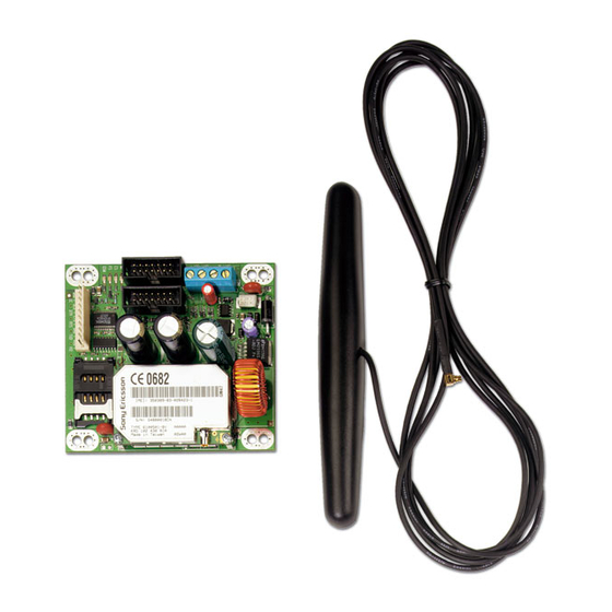
The ATS7300 enables alarm reporting via GSM. All reporting
formats available through PSTN are fully functional, including voice
reporting or audio listen-in.The GSM module can be used for
primary reporting as well as back-up reporting (using multiple
central stations).
The ATS7300 has a provision to establish a reliable connection for
remote up-/downloading to and from the ATS panel. In data mode
the GSM module even can establish a connection up to 4800 baud
(for more details and programming options see ATS2000 / 3000 /
4000 Programming manual). A general fault indicator is available
(OC) to indicate if the battery is present, the battery fuse is ok and
the GSM network is detected.
IMPORTANT:
Disable PIN code request on your SIM card (via
any mobile telephone)
For proper operation a GSM card with subscription
is mandatory (NOT pre-paid).
The ATS7300 will only operate (dial/answer) when
connected to the home network.
A GSM module during operation can require a
maximum of 2A peak current; the back-up battery
normally wired to the control panel is now also
wired to the GSM module. The GSM module
checks the battery operation and disconnects the
battery when the battery voltage drops below 9
volts to preserve the battery (deep discharge
protection)
Make sure the antenna itself is placed outside the
control panel.
To do up/download via the GSM module, use a SIM
card that has fax and data enabled.
M
OUNTING LOCATION
The ATS7300 must be mounted inside an ATS panel housing.
Important:
1. Disconnect the mains power before opening the cabinet.
Disconnect AC mains plug from AC mains wall socket.
OR
Disconnect the mains with a dedicated circuit breaker.
2. Disconnect the battery (when applicable).
M
OUNTING THE UNIT
Mounting the ATS7300 into the control panel (ATS4000, Ref.
to figure
).
1. Remove the screws
2. Place the extension pillars with the plastic rings on top of the
existing pillars
3. Place the clips in the square holes
4. Mount the ATS7300 using the screws and extension pillars
5. Place the ATS control panel PCB back into its original position.
Mounting the ATS7300 into the control panel
(ATS2000/3000/4500, Ref. to figure
1. Place the clips in the square holes
available).
2. Mount the ATS7300 using screws.
Connecting the GSM module
Disconnect AC mains plug from AC mains wall socket
1. Remove the battery wires that run from the battery to the
control panel.
2. Add the blue "tap connectors" to the red and blue (or black)
battery leads.
3. Connect the additional wires, which will be clamped to the
GSM module.
4. Before clamping ensure that the battery leads will reach the
GMS module as well as the battery.
5. Connect the red wire to BATT IN + and the battery.
6. Connect the blue (or black) wire to BATT IN – and the battery.
© 2003 GE Interlogix B.V.
All Rights Reserved
GSM Module
10
9
8
7
6
5
4
3
2
1
GSM Module
and lift off the control panel PCB.
.
.
)
(use metal pillars when
ATS7300
.
1047430
12/2003
Advertisement

Related Manuals for GE ARITECH ATS7300


Summary of Contents for GE ARITECH ATS7300
- Page 1 ATS7300 GSM Module Gouvars, Frederique (IndSys, GE Interlogix) GSM Module Important: OES IT The ATS7300 enables alarm reporting via GSM. All reporting 1. Disconnect the mains power before opening the cabinet. formats available through PSTN are fully functional, including voice Disconnect AC mains plug from AC mains wall socket.
- Page 2 7. (Optional) Connect the open collector output to an external The MI LED (green) displays the status of the communication signalling device or panel to have an independent fault interface to the panel. supervisory. Table 1. MI LED status 8. Connect the flat cable between the control panel (connector J20) and the ATS7300 (connector CON1or CON2).
- Page 3 Dimensions 80 mm x 90 mm Battery type and max. capacity lead acid rechargeable 18 Ah 12 V nom. (BS131) Weight 160 gr. Temperature 10°C to +50°C Relative humidity 95 % Module GSM Montage de l’ATS7300 à l’intérieur de la centrale UELLE EST SA FONCTION (ATS2000/3000/4500, voir la figure L’ATS7300 autorise une transmission d’alarme via GSM.
- Page 4 La sortie bascule au niveau haut si une de ces conditions n’est pas Description remplie. Facteur Taux d’utilisation (+/- 10%) IMPORTANT: 100% Connecté Hors ligne Après la mise sous tension, la sortie à collecteur ouvert est au Connexion en cours niveau haut jusqu’à...
- Page 5 CON5 SIM-voet. Voor de aansluiting van de SIM- Controleer of de antenne zelf buiten het kaart van de GSM. controlepaneel is geïnstalleerd. CON3 Optieconnector. OC kan Indien up/download via de GSM module wordt gebruikt worden om een toegepast, dient de fax en datafunctie op de SIM storing in de zekering (F1) kaart actief aangezet te worden.
- Page 6 De VS LED (groen) geeft de veldsterkte of de signaalsterkte weer Beschrijving die ontvangen wordt door de GSM-module. Het aantal keer Inscha- Percen- knipperen geeft het niveau aan. Tussen het knipperen zit een keltijd tage pauze van 1 seconde. (+/- 10 %) 25 % 1 sec Initialisatie OK, wachten op...
- Page 7 L’uscita open collector segnala lo stato del fusibile batteria (F1), la presenza della batteria e del segnale della rete GSM. ’ ONTAGGIO DELL UNITÀ L’uscita è attiva (bassa) se è presente la batteria, il fusibile è Montaggio dell’unità ATS7300 nella centrale di controllo efficiente e c’è...
-
Page 8: Ważne Informacje
Descrizione Il modulo GSM segnalerà un guasto linea alla centrale di controllo Lampeggiante Alimentazione attivata, modulo se non rileverà la rete telefonica per un minuto. collegato a una rete. Acceso Alimentazione attivata, modulo non collegato a una rete. Specifiche tecniche Alimentazione Mediante cavo a nastro dalla centrale di controllo 10 –... -
Page 9: Diody Led
Podłącz niebieski (lub czarny) przewód do zacisku BATT IN - Dioda MI (zielona) wskazuje stan interfejsu komunikacyjnego do oraz bieguna ujemnego baterii. centrali alarmowej. (Opcjonalnie) Podłącz wyjście sygnalizacyjne do Tabela 1. Stan diody MI zewnętrznego urządzenia sygnalizacyjnego lub centrali alarmowej, aby uzyskać niezależną sygnalizację awarii. Opis Podłącz płaski kabel pomiędzy centralą... - Page 10 Magistrala MI 20 mA GSM Offline 15 mA GSM Online 110 mA GSM Online (szczytowy) Prąd wyjściowy układu z otwartym kolektorem (CON3, OC) 15 mA max. przy 13.8 VDC. Zasilanie bateryjne (CON1, + i -) NIE UŻYWAĆ Wymiary 80 mm x 90 mm Typ baterii oraz pojemność...
- Page 11 N.º Descrição Função Descrição outputs de falha) CON 2/CON 4 Faz a comunicação entre o CON 2/CON 4 Faz a comunicação entre o (conector do ATS7300 e o painel (conector do ATS7300 e o painel sistema) principal. sistema) principal. LEDs que indicam o estado. LEDs que indicam o estado.
- Page 12 Descrição Descrição Intermitente (1 – 5) Indicação nível de sinal, de má (1) a Desligado Não há alimentação ou o módulo excelente (5) está desligado Ligado Alimentação ligada, não estando Intermitente Alimentação ligada, ligado a uma ligado a uma rede rede Ligado Alimentação ligada, não estando...
- Page 13 Utgangen har samme funksjonalitet som linje feil, som rapporteres til sentralappararttet, bortsett fra at utgangen ikke er forsinket. Montering av ATS7300 i sentralapparatet (ATS2000/3000/4500, se figur Linjefeil som rapporteres til sentralapparatet er forsinket med 1 minutt. 1. Sett klypene i firkanthullene (bruk metallpilarer om nødvendig).
- Page 14 GSM Online 110 mA GSM Online Peak Strøm på åpen kollektorutgang (CON1, OC) 15 mA maks. ved 13,8 V . Dimensjoner 80 mm x 90 mm Batteritype og maks. kapasitet blysyre, gjenoppladbart 18 Ah 12 V nom. (BS131) Vekt 160 g Temperatur 10°C - +50°C Relativ fuktighet...
- Page 15 Nº Descripción Función Descripción CON 2/CON 4 Comunica al ATS7300 con Ciclo de Velocidad (Conector del el panel principal. trabajo (+/- 10%) sistema) a que se reinicie Estado de los LED. El LED CS (Rojo) indica el estado de los datos de audio ALIDA DE INDICADOR DE ALLO transmitidos a la central receptora.
- Page 16 GSM Modul Før tilslutning skal det sikres at akkumulator ledningerne ØR kan nå fra GMS modulet til Akkumulatoren. ATS7300 gør det muligt at foretage en alarmtransmission via Tilslut den røde ledning til BATT IN + og akkumulatoren GSM. Alle de transmissionsformater, der står til rådighed Tilslut den blå...
- Page 17 Beskrivelse Tabel 3. FS LED status Aktivitets- Varighed Beskrivelse periode (+/- 10%) Ingen feltstyrke (intet netværk kommunikation detekteret) 1 sek. Alt OK, kommunikation i gang Pulser (1 – 5) Angivelse af feltstyrke fra ringe (1) til 500 ms Hardwarefejl udmærket (5) 250 ms Kommunikationsfejl, afventer Spænding til, ikke tilsluttet noget...
- Page 18 3. Placera clipsen i de fyrkantiga hålen 4. Montera ATS7300 med hjälp av skruvarna och Lysdioden MI (grön) visar status för expansionspinnarna kommunikationsgränssnittet till centralapparaten. 5. Placera ATS-centralapparatens PCB i sitt originalläge. Tabell 1. MI-lysdiodstatus LYSDIOD Beskrivning Montera ATS7300 i centralapparaten (ATS2000/3000/4500,...
- Page 19 LYSDIOD Beskrivning GSM-modulen signalerar ett linjefel till centralapparaten om GSM-modulen inte hittar den egna operatörens nätverk inom 1 Tänd Strömförsörjning sker, ej ansluten till minut. ett nätverk Tekniska specifikationer Matningsspänning Via bandkabel från centralapparaten 10 – 15 V Via CON1, BAT från backuppbatteriet 10 –...
-
Page 20: Manufacturer's Declaration Of Conformity
MANUFACTURERS DECLARATION OF CONFORMITY Product identification: Model/type : ATS7300 Category (description) : GSM Module Brand : GE-InterlogiX/ Aritech / SLC Technologies / Sentrol/ ESL/ Tecom GE Interlogix B.V. Manufacturer: Kelvinstraat 7 6003 DH Weert, The Netherlands EU Representative: Concerning RTTE...
Need help?
Do you have a question about the ARITECH ATS7300 and is the answer not in the manual?
Questions and answers