GE B30 Instruction Manual
Bus differential system, ur series
Hide thumbs
Also See for B30:
- Instruction manual (633 pages) ,
- Communications manual (532 pages) ,
- Technical reference manual (252 pages)
Table of Contents
Advertisement
Quick Links
Title Page
GE
Grid Solutions
GE Grid Solutions
650 Markland Street
Markham, Ontario
Canada L6C 0M1
Tel: +1 905 927 7070 Fax: +1 905 927 5098
Internet:
http://www.GEGridSolutions.com
*1601-0109-V2*
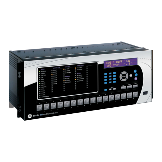
B30 Bus Differential System
UR Series Instruction Manual
B30 revision: 5.8x
Manual P/N: 1601-0109-V2 (GEK-113543A)
Copyright © 2017 GE Multilin Inc.
E83849
LISTED
IND.CONT. EQ.
52TL
GE Multilin's Quality Management
System is registered to
ISO9001:2008
QMI # 005094
UL # A3775
Advertisement
Table of Contents

Related Manuals for GE B30


Summary of Contents for GE B30
- Page 1 Title Page Grid Solutions B30 Bus Differential System UR Series Instruction Manual B30 revision: 5.8x Manual P/N: 1601-0109-V2 (GEK-113543A) Copyright © 2017 GE Multilin Inc. E83849 GE Grid Solutions LISTED 650 Markland Street IND.CONT. EQ. 52TL Markham, Ontario GE Multilin's Quality Management...
- Page 3 Addendum ADDENDUM This addendum contains information that relates to the B30 Bus Differential System, version 5.8x. This addendum lists a number of information items that appear in the instruction manual GEK-113543A (revision V2) but are not included in the current B30 operations.
-
Page 5: Table Of Contents
1.3 ENERVISTA UR SETUP SOFTWARE 1.3.1 REQUIREMENTS ....................1-6 1.3.2 SOFTWARE INSTALLATION ................1-6 1.3.3 CONFIGURING THE B30 FOR SOFTWARE ACCESS ........1-8 1.3.4 USING THE QUICK CONNECT FEATURE............. 1-10 1.3.5 CONNECTING TO THE B30 RELAY............... 1-16 1.4 UR HARDWARE 1.4.1... - Page 6 5.2.11 CONTROL PUSHBUTTONS ................5-45 5.2.12 USER-PROGRAMMABLE PUSHBUTTONS............5-46 5.2.13 FLEX STATE PARAMETERS ................5-51 5.2.14 USER-DEFINABLE DISPLAYS ................5-52 5.2.15 DIRECT INPUTS AND OUTPUTS..............5-54 5.2.16 TELEPROTECTION ..................5-62 5.2.17 INSTALLATION ....................5-63 5.3 REMOTE RESOURCES 5.3.1 REMOTE RESOURCES CONFIGURATION............5-64 B30 Bus Differential System GE Multilin...
- Page 7 TEST MODE ....................5-182 5.10.2 FORCE CONTACT INPUTS ................5-183 5.10.3 FORCE CONTACT OUTPUTS ..............5-184 6. ACTUAL VALUES 6.1 OVERVIEW 6.1.1 ACTUAL VALUES MAIN MENU ................ 6-1 6.2 STATUS 6.2.1 CONTACT INPUTS.................... 6-3 GE Multilin B30 Bus Differential System...
- Page 8 SECURING AND LOCKING FLEXLOGIC™ EQUATIONS ......8-10 8.2.3 SETTINGS FILE TRACEABILITY..............8-12 8.3 ENERVISTA SECURITY MANAGEMENT SYSTEM 8.3.1 OVERVIEW ......................8-15 8.3.2 ENABLING THE SECURITY MANAGEMENT SYSTEM........8-15 8.3.3 ADDING A NEW USER ..................8-15 8.3.4 MODIFYING USER PRIVILEGES ..............8-16 viii B30 Bus Differential System GE Multilin...
- Page 9 FLEXANALOG ITEMS ..................A-1 A.1.2 FLEXINTEGER ITEMS ..................A-10 PARAMETERS B. MODBUS B.1 MODBUS RTU PROTOCOL COMMUNICATIONS B.1.1 INTRODUCTION....................B-1 B.1.2 PHYSICAL LAYER.....................B-1 B.1.3 DATA LINK LAYER....................B-1 B.1.4 CRC-16 ALGORITHM..................B-2 B.2 MODBUS FUNCTION CODES B.2.1 SUPPORTED FUNCTION CODES ..............B-3 GE Multilin B30 Bus Differential System...
- Page 10 ACSI MODELS CONFORMANCE STATEMENT ..........C-22 C.6.3 ACSI SERVICES CONFORMANCE STATEMENT ......... C-23 C.7 LOGICAL NODES C.7.1 LOGICAL NODES TABLE ................C-26 D. IEC 60870-5-104 D.1 IEC 60870-5-104 COMMUNICATIONS D.1.1 INTEROPERABILITY DOCUMENT..............D-1 D.1.2 IEC 60870-5-104 POINTS ................. D-9 B30 Bus Differential System GE Multilin...
- Page 11 COUNTERS .....................E-10 E.2.4 ANALOG INPUTS ....................E-11 F. MISCELLANEOUS F.1 CHANGE NOTES F.1.1 REVISION HISTORY ..................F-1 F.1.2 CHANGES TO THE B30 MANUAL..............F-2 F.2 ABBREVIATIONS F.2.1 STANDARD ABBREVIATIONS ................. F-9 F.3 WARRANTY F.3.1 GE MULTILIN WARRANTY ................F-11 INDEX GE Multilin...
- Page 12 TABLE OF CONTENTS B30 Bus Differential System GE Multilin...
-
Page 13: Getting Started
Product disassembly and repairs are not permitted. All service needs to be conducted by the factory. This product is rated to Class A emissions levels and is to be used in Utility, Substation Industrial environments. Not to be used near electronic devices rated for Class B levels. GE Multilin B30 Bus Differential System... -
Page 14: Inspection Checklist
• Mounting screws. For product information, instruction manual updates, and the latest software updates, please visit the GE Grid Solutions website. If there is any noticeable physical damage, or any of the contents listed are missing, contact GE Multilin immedi- ately. NOTE... -
Page 15: Ur Overview
This new generation of equipment must also be easily incorporated into automation systems, at both the station and enterprise levels. The GE Multilin Universal Relay (UR) has been developed to meet these goals. GE Multilin... -
Page 16: Hardware Architecture
(dual) ring configuration. This feature is optimized for speed and intended for pilot- aided schemes, distributed logic applications, or the extension of the input/output capabilities of a single relay chassis. B30 Bus Differential System GE Multilin... -
Page 17: Ur Software Architecture
Employing OOD/OOP in the software architecture of the B30 achieves the same features as the hardware architecture: modularity, scalability, and flexibility. The application software for any UR-series device (for example, feeder protection, transformer protection, distance protection) is constructed by combining objects from the various functionality classes. -
Page 18: Enervista Ur Setup Software
Video capable of displaying 800 x 600 or higher in high-color mode (16-bit color) • RS232 and/or Ethernet port for communications to the relay The following qualified modems have been tested to be compliant with the B30 and the EnerVista UR Setup software. • US Robotics external 56K FaxModem 5686 •... - Page 19 Install Software window as shown below. Select the “Web” option to ensure the most recent software release, or select “CD” if you do not have a web connection, then click the Add Now button to list software items for the B30.
-
Page 20: Configuring The B30 For Software Access
OVERVIEW The user can connect remotely to the B30 through the rear RS485 port or the rear Ethernet port with a PC running the EnerVista UR Setup software. The B30 can also be accessed locally with a laptop computer through the front panel RS232 port or the rear Ethernet port using the Quick Connect feature. - Page 21 COMMUNICATIONS SERIAL PORTS 10. Click the Read Order Code button to connect to the B30 device and upload the order code. If an communications error occurs, ensure that the EnerVista UR Setup serial communications values entered in the previous step correspond to the relay setting values.
-
Page 22: Using The Quick Connect Feature
MODBUS PROTOCOL 11. Click the Read Order Code button to connect to the B30 device and upload the order code. If an communications error occurs, ensure that the three EnerVista UR Setup values entered in the previous steps correspond to the relay setting values. - Page 23 B30. This ensures that configuration of the EnerVista UR Setup software matches the B30 model number. b) USING QUICK CONNECT VIA THE REAR ETHERNET PORTS To use the Quick Connect feature to access the B30 from a laptop through Ethernet, first assign an IP address to the relay from the front panel keyboard.
- Page 24 Right-click the Local Area Connection icon and select Properties. Select the Internet Protocol (TCP/IP) item from the list provided and click the Properties button. Click on the “Use the following IP address” box. 1-12 B30 Bus Differential System GE Multilin...
- Page 25 1 GETTING STARTED 1.3 ENERVISTA UR SETUP SOFTWARE Enter an IP address with the first three numbers the same as the IP address of the B30 relay and the last number different (in this example, 1.1.1.2). Enter a subnet mask equal to the one set in the B30 (in this example, 255.0.0.0).
- Page 26 If this computer is used to connect to the Internet, re-enable any proxy server settings after the laptop has been discon- nected from the B30 relay. Verify that the latest version of the EnerVista UR Setup software is installed (available from the GE enerVista CD or online from http://www.gegridsolutions.com/multilin). See the Software Installation section for installation details.
- Page 27 Each time the EnerVista UR Setup software is initialized, click the Quick Connect button to establish direct communica- tions to the B30. This ensures that configuration of the EnerVista UR Setup software matches the B30 model number. When direct communications with the B30 via Ethernet is complete, make the following changes: From the Windows desktop, right-click the My Network Places icon and select Properties to open the network connections window.
-
Page 28: Connecting To The B30 Relay
The EnerVista UR Setup software has several new quick action buttons that provide users with instant access to several functions that are often performed when using B30 relays. From the online window, users can select which relay to interro- gate from a pull-down window, then click on the button for the action they wish to perform. The following quick action func- tions are available: •... -
Page 29: Ur Hardware
Figure 1–7: RELAY COMMUNICATIONS OPTIONS To communicate through the B30 rear RS485 port from a PC RS232 port, the GE Multilin RS232/RS485 converter box is required. This device (catalog number F485) connects to the computer using a “straight-through” serial cable. A shielded twisted-pair (20, 22, or 24 AWG) connects the F485 converter to the B30 rear communications port. -
Page 30: Using The Relay
LED off. The relay in the “Not Programmed” state will block signaling of any output relay. These conditions will remain until the relay is explicitly put in the “Programmed” state. Select the menu message SETTINGS PRODUCT SETUP INSTALLATION RELAY SETTINGS RELAY SETTINGS: Not Programmed 1-18 B30 Bus Differential System GE Multilin... -
Page 31: Relay Passwords
See the Changing Settings section in Chapter 4 for complete instructions on setting up security level passwords. NOTE 1.5.6 FLEXLOGIC™ CUSTOMIZATION FlexLogic™ equation editing is required for setting up user-defined logic for customizing the relay operations. See the Flex- Logic™ section in Chapter 5 for additional details. GE Multilin B30 Bus Differential System 1-19... -
Page 32: Commissioning
1 GETTING STARTED 1.5.7 COMMISSIONING The B30 requires a minimum amount of maintenance when it is commissioned into service. Since the B30 is a micropro- cessor-based relay, its characteristics do not change over time. As such, no further functional tests are required. -
Page 33: Product Description
Another option provides two 10Base-F fiber optic ports for redundancy. The Ethernet port supports IEC 61850, Modbus TCP, and TFTP protocols, and allows access to the relay via any standard web browser (B30 web pages). The IEC 60870- 5-104 protocol is supported on the Ethernet port. DNP 3.0 and IEC 60870-5-104 cannot be enabled at the same time. - Page 34 2.1 INTRODUCTION 2 PRODUCT DESCRIPTION Figure 2–1: SINGLE LINE DIAGRAM B30 Bus Differential System GE Multilin...
-
Page 35: Ordering
2.1.2 ORDERING a) OVERVIEW The B30 is available as a 19-inch rack horizontal mount or reduced-size (¾) vertical unit and consists of the following mod- ules: power supply, CPU, CT/VT, digital input and output, transducer input and output, and inter-relay communications. - Page 36 2.1 INTRODUCTION 2 PRODUCT DESCRIPTION Table 2–3: B30 ORDER CODES FOR HORIZONTAL UNITS * - F - W/X Full Size Horizontal Mount BASE UNIT Base Unit SOFTWARE No software options Ethernet Global Data (EGD) protocol (IEC 61850 options not IEC 61850 protocol...
- Page 37 2 PRODUCT DESCRIPTION 2.1 INTRODUCTION The order codes for the reduced size vertical mount units with traditional CTs and VTs are shown below. Table 2–4: B30 ORDER CODES (REDUCED SIZE VERTICAL UNITS) * - F Reduced Size Vertical Mount BASE UNIT...
- Page 38 2 PRODUCT DESCRIPTION c) ORDER CODES WITH PROCESS BUS MODULES The order codes for the horizontal mount units with the process bus module are shown below. Table 2–5: B30 ORDER CODES (HORIZONTAL UNITS WITH PROCESS BUS) * - F - W/X...
-
Page 39: Replacement Modules
Replacement modules can be ordered separately as shown below. When ordering a replacement CPU module or face- plate, please provide the serial number of your existing unit. Not all replacement modules may be applicable to the B30 relay. Only the modules specified in the order codes are available as replacement modules. - Page 40 4 dcmA inputs, 4 dcmA outputs (only one 5A or 5D module is allowed) 8 RTD inputs INPUTS/OUTPUTS 4 RTD inputs, 4 dcmA outputs (only one 5A or 5D module is allowed) 4 dcmA inputs, 4 RTD inputs 8 dcmA inputs B30 Bus Differential System GE Multilin...
- Page 41 4 dcmA inputs, 4 dcmA outputs (only one 5A or 5D module is allowed) 8 RTD inputs INPUTS/OUTPUTS 4 RTD inputs, 4 dcmA outputs (only one 5A or 5D module is allowed) 4 dcmA inputs, 4 RTD inputs 8 dcmA inputs GE Multilin B30 Bus Differential System...
-
Page 42: Specifications
IEEE Moderately/Very/Extremely Operate time: <30 ms at 0.9 pickup at 60 Hz for Defi- Inverse; IEC (and BS) A/B/C and Short nite Time mode Inverse; GE IAC Inverse, Short/Very/ Extremely Inverse; I t; FlexCurves™ NEUTRAL OVERVOLTAGE (programmable); Definite Time (0.01 s Pickup level: 0.000 to 3.000 pu in steps of 0.001... -
Page 43: User-Programmable Elements
LEDs on Test sequence 2: all LEDs off, one LED at a time on for 1 s Test sequence 3: all LEDs on, one LED at a time off for 1 s GE Multilin B30 Bus Differential System 2-11... -
Page 44: Monitoring
< 0.2 VA at rated secondary Conversion range: 0.02 to 46 × CT rating RMS symmetrical Standard CT: Sensitive Ground CT module: 0.002 to 4.6 × CT rating RMS symmetrical Current withstand: 20 ms at 250 times rated 2-12 B30 Bus Differential System GE Multilin... -
Page 45: Power Supply
Minimum AC voltage: 88 V at 25 to 100 Hz NOTE: Low range is DC only. Maximum AC voltage: 265 V at 25 to 100 Hz Voltage loss hold-up: 200 ms duration at nominal GE Multilin B30 Bus Differential System 2-13... -
Page 46: Outputs
Time delay: 1 ms for AM input 40 μs for DC-shift input Isolation: 2 kV CONTROL POWER EXTERNAL OUTPUT (FOR DRY CONTACT INPUT) Capacity: 100 mA DC at 48 V DC Isolation: ±300 Vpk 2-14 B30 Bus Differential System GE Multilin... -
Page 47: Communications
1200 m G.703 100 m RS422 distance is based on transmitter power and does not take into consideration the clock source NOTE provided by the user. LINK POWER BUDGET AND MAXIMUM OPTICAL INPUT POWER GE Multilin B30 Bus Differential System 2-15... - Page 48 At extreme temperatures these values deviate based on component tolerance. On average, the output power decreases as the temperature is increased by a factor 1dB / 5°C. 2-16 B30 Bus Differential System GE Multilin...
-
Page 49: Environmental
Operating temperature: –40 to 60°C; the LCD contrast may be Pollution degree: impaired at temperatures less than – Overvoltage category: 20°C Ingress protection: IP20 front, IP10 back HUMIDITY Humidity: operating up to 95% (non-condensing) at 55°C (as per IEC60068-2-30 variant 1, 6days). GE Multilin B30 Bus Differential System 2-17... -
Page 50: Type Tests
20 V/m, 80 MHz to 1 GHz Safety UL508 e83849 NKCR Safety UL C22.2-14 e83849 NKCR7 Safety UL1053 e83849 NKCR 2.2.12 PRODUCTION TESTS THERMAL Products go through an environmental test based upon an Accepted Quality Level (AQL) sampling process. 2-18 B30 Bus Differential System GE Multilin... -
Page 51: Approvals
Units that are stored in a de-energized state should be powered up once per year, for one hour continuously, to NOTE avoid deterioration of electrolytic capacitors. GE Multilin B30 Bus Differential System 2-19... - Page 52 2.2 SPECIFICATIONS 2 PRODUCT DESCRIPTION 2-20 B30 Bus Differential System GE Multilin...
-
Page 53: Hardware
HORIZONTAL UNITS The B30 Bus Differential System is available as a 19-inch rack horizontal mount unit with a removable faceplate. The face- plate can be specified as either standard or enhanced at the time of ordering. The enhanced faceplate contains additional user-programmable pushbuttons and LED indicators. - Page 54 VERTICAL UNITS The B30 Bus Differential System is available as a reduced size (¾) vertical mount unit, with a removable faceplate. The faceplate can be specified as either standard or enhanced at the time of ordering. The enhanced faceplate contains addi- tional user-programmable pushbuttons and LED indicators.
- Page 55 RS232 communications port. The relay is secured to the panel with the use of four screws supplied with the relay. 11.015” 7.482” 1.329” 13.560” 15.000” 14.025” 4.000” 9.780” 843809A1.CDR Figure 3–4: B30 VERTICAL DIMENSIONS (ENHANCED PANEL) GE Multilin B30 Bus Differential System...
- Page 56 UR S RI S UR S RI S Figure 3–5: B30 VERTICAL MOUNTING AND DIMENSIONS (STANDARD PANEL) For details on side mounting B30 devices with the enhanced front panel, refer to the following documents available online from the GE Grid Solutions website. •...
- Page 57 3 HARDWARE 3.1 DESCRIPTION Figure 3–6: B30 VERTICAL SIDE MOUNTING INSTALLATION (STANDARD PANEL) GE Multilin B30 Bus Differential System...
- Page 58 3.1 DESCRIPTION 3 HARDWARE Figure 3–7: B30 VERTICAL SIDE MOUNTING REAR DIMENSIONS (STANDARD PANEL) B30 Bus Differential System GE Multilin...
-
Page 59: Module Withdrawal And Insertion
The enhanced faceplate can be opened to the left, once the thumb screw has been removed, as shown below. This allows for easy accessibility of the modules for withdrawal. The new wide-angle hinge assembly in the enhanced front panel opens completely and allows easy access to all modules in the B30. 842812A1.CDR Figure 3–8: UR MODULE WITHDRAWAL AND INSERTION (ENHANCED FACEPLATE) -
Page 60: Rear Terminal Layout
NOTE The 4.0x release of the B30 relay includes new hardware modules.The new CPU modules are specified with codes 9E and higher. The new CT/VT modules are specified with the codes 8F and higher. - Page 61 (rows 1 to 8), use a minimum of 17 inch-pounds. During manufacturing, the power supply and CPU modules are installed in slots B and D of the chassis with 13 inch-pounds of torque on the screws at the top and bottom of the modules. GE Multilin B30 Bus Differential System...
-
Page 62: Wiring
SURGE FILTER No. 10AWG 836773A6.CDR Minimum GROUND BUS MODULE ARRANGEMENT MODULES MUST BE GROUNDED IF TERMINAL IS PROVIDED Power Inputs/ Inputs/ Inputs/ outputs outputs Supply outputs * Optional Figure 3–12: TYPICAL WIRING DIAGRAM 3-10 B30 Bus Differential System GE Multilin... -
Page 63: Dielectric Strength
(see the Self-test errors section in chapter 7) or control power is lost, the relay will de-energize. For high reliability systems, the B30 has a redundant option in which two B30 power supplies are placed in parallel on the bus. -
Page 64: Ct/Vt Modules
Figure 3–13: CONTROL POWER CONNECTION When using an SH/SL power supply module or a B30 with the HardFiber system, before powering off the B30, save data in the compact flash memory using Commands > Relay Maintenance > Save Non-Volatile Data. When not NOTE saved or the relay loses power, up to the last two minutes of data is not saved to the compact flash memory. - Page 65 Substitute the tilde “~” symbol with the slot position of the module in the following figure. NOTE Current inputs Voltage inputs 8F, 8G, 8L, and 8M modules (4 CTs and 4 VTs) Current inputs 8H, 8J, 8N, and 8R modules (8 CTs) 842766A3.CDR Figure 3–15: CT/VT MODULE WIRING GE Multilin B30 Bus Differential System 3-13...
-
Page 66: Process Bus Modules
3.2.5 PROCESS BUS MODULES The B30 can be ordered with a process bus interface module. This module is designed to interface with the GE Multilin HardFiber system, allowing bi-directional IEC 61850 fiber optic communications with up to eight HardFiber merging units, known as Bricks. - Page 67 Wherever a tilde “~” symbol appears, substitute with the slot position of the module; wherever a number sign “#” appears, substitute the contact number NOTE GE Multilin B30 Bus Differential System 3-15...
- Page 68 Form-C ~6a, ~6c 2 Inputs Fast Form-C ~7a, ~7c 2 Inputs ~7a, ~7c 2 Inputs ~7a, ~7c 2 Inputs Fast Form-C ~8a, ~8c 2 Inputs ~8a, ~8c 2 Inputs ~8a, ~8c 2 Inputs 3-16 B30 Bus Differential System GE Multilin...
- Page 69 Not Used ~5a, ~5c 2 Inputs 2 Outputs Solid-State Solid-State ~6a, ~6c 2 Inputs 2 Outputs Not Used Not Used ~7a, ~7c 2 Inputs 2 Outputs Solid-State Solid-State ~8a, ~8c 2 Inputs Not Used GE Multilin B30 Bus Differential System 3-17...
- Page 70 3.2 WIRING 3 HARDWARE Figure 3–17: CONTACT INPUT AND OUTPUT MODULE WIRING (1 of 2) 3-18 B30 Bus Differential System GE Multilin...
- Page 71 CONTACT IN CONTACT IN COMMON SURGE 842763A2.CDR Figure 3–18: CONTACT INPUT AND OUTPUT MODULE WIRING (2 of 2) Observe correct polarity for all contact input and solid state output connections for proper functional- ity. GE Multilin B30 Bus Differential System 3-19...
- Page 72 B30 input even when the output is open, if there is a substantial distributed capacitance (represented by C1) present in the wiring between the output and the B30 input and the debounce time setting in the B30 relay is low enough.
- Page 73 This operation of contact inputs also can be prevented by using the Auto-Burnish contact inputs or contact inputs with active impedance. Figure 3–21: CONTACT INPUT CONNECTED TO A CONTACT OUTPUT WITH RESISTOR (R2) ACROSS THE INPUT GE Multilin B30 Bus Differential System 3-21...
- Page 74 (EQ 3.2) The 2 mA current is used in case the contact input is connected across the GE Form A contact output with voltage monitoring. Otherwise use the amperage of the active circuit connected to the contact input when its contact output is open and the voltage across the contact input is third trigger threshold to calculate the resistor value.
- Page 75 (refer to the Contact Input and Output Module Wiring diagrams). This is beneficial when connecting contact inputs to separate voltage sources. Con- sequently, the threshold voltage setting is also defined per group of two contact inputs. GE Multilin B30 Bus Differential System 3-23...
- Page 76 Contact inputs susceptible to parasitic capacitance caused by long cable runs affected by switching surges from external circuits can result in inadvertent activation of contact inputs with the external contact open. In this case, GE recommends using the digital I/O module with active impedance circuit.
- Page 77 3 HARDWARE 3.2 WIRING Figure 3–24: ACTIVE IMPEDANCE CONTACT INPUT V-I CHARACTERISTIC GE Multilin B30 Bus Differential System 3-25...
-
Page 78: Transducer Inputs And Outputs
(5A, 5C, 5D, 5E, and 5F) and channel arrangements that may be ordered for the relay. Wherever a tilde “~” symbol appears, substitute with the slot position of the module. NOTE Figure 3–25: TRANSDUCER INPUT/OUTPUT MODULE WIRING 3-26 B30 Bus Differential System GE Multilin... -
Page 79: Rs232 Faceplate Port
3.2.8 RS232 FACEPLATE PORT A 9-pin RS232C serial port is located on the B30 faceplate for programming with a personal computer. All that is required to use this interface is a personal computer running the EnerVista UR Setup software provided with the relay. Cabling for the RS232 port is shown in the following figure for both 9-pin and 25-pin connectors. - Page 80 For instance, the relays must be connected with all RS485 “+” terminals connected together, and all RS485 “–” terminals connected together. Though data is transmitted over a two-wire twisted pair, all RS485 devices require a shared 3-28 B30 Bus Differential System GE Multilin...
- Page 81 This common voltage is implied to be a power supply common. Some systems allow the shield (drain wire) to be used as common wire and to connect directly to the B30 COM terminal (#3); others function cor- rectly only if the common wire is connected to the B30 COM terminal, but insulated from the shield.
- Page 82 For optical power budgeting, splices are required every 1 km for the transmitter/receiver pair. When splicing optical fibers, the diameter and numerical aperture of each fiber must be the same. In order to engage or disengage the ST type connec- tor, only a quarter turn of the coupling is required. 3-30 B30 Bus Differential System GE Multilin...
-
Page 83: Irig-B
UR-series relays can be synchronized. The IRIG-B repeater has a bypass function to maintain the time signal even when a relay in the series is powered down. Figure 3–30: IRIG-B REPEATER Using an amplitude modulated receiver will cause errors up to 1 ms in event time-stamping. NOTE GE Multilin B30 Bus Differential System 3-31... -
Page 84: Direct Input And Output Communications
3.3.1 DESCRIPTION The B30 direct inputs and outputs feature makes use of the type 7 series of communications modules. These modules are also used by the L90 Line Differential Relay for inter-relay communications. The direct input and output feature uses the communications channels provided by these modules to exchange digital state information between relays. - Page 85 These modules are listed in the following table. All fiber modules use ST type connectors. Not all the direct input and output communications modules may be applicable to the B30 relay. Only the modules specified in the order codes are available as direct input and output communications modules.
- Page 86 Channel 1: G.703, channel 2: 1300 nm, single-mode, laser G.703, 1 channel G.703, 2 channels RS422, 1 channel RS422, 2 channels, 2 clock inputs RS422, 2 channels Observing any fiber transmitter output can cause eye injury. 3-34 B30 Bus Differential System GE Multilin...
-
Page 87: Fiber: Led And Eled Transmitters
When using a laser Interface, attenuators may be necessary to ensure that you do not exceed the maximum optical input power to the receiver. When using a laser Interface, attenuators may be necessary to ensure that you do not exceed the maximum optical input power to the receiver. GE Multilin B30 Bus Differential System 3-35... -
Page 88: Interface
Remove the top cover by sliding it towards the rear and then lift it upwards. Set the timing selection switches (channel 1, channel 2) to the desired timing modes. Replace the top cover and the cover screw. 3-36 B30 Bus Differential System GE Multilin... - Page 89 For connection to a higher order system (UR- to-multiplexer, factory defaults), set to octet timing (S1 = ON) and set timing mode to loop timing (S5 = OFF and S6 = OFF). GE Multilin B30 Bus Differential System 3-37...
- Page 90 G.703 line side of the interface while the other lies on the differential Manchester side of the interface. DMR = Differential Manchester Receiver DMX = Differential Manchester Transmitter G7X = G.703 Transmitter G7R = G.703 Receiver 842775A1.CDR Figure 3–41: G.703 DUAL LOOPBACK MODE 3-38 B30 Bus Differential System GE Multilin...
-
Page 91: Rs422 Interface
1 as shown below. If the terminal timing feature is not available or this type of connection is not desired, the G.703 interface is a viable option that does not impose timing restrictions. GE Multilin B30 Bus Differential System 3-39... - Page 92 Figure 3–44: TIMING CONFIGURATION FOR RS422 TWO-CHANNEL, 3-TERMINAL APPLICATION Data module 1 provides timing to the B30 RS422 interface via the ST(A) and ST(B) outputs. Data module 1 also provides timing to data module 2 TT(A) and TT(B) inputs via the ST(A) and AT(B) outputs. The data module pin numbers have been omitted in the figure above since they may vary depending on the manufacturer.
-
Page 93: Rs422 And Fiber Interface
When using a laser interface, attenuators can be necessary to ensure that you do not exceed the maximum optical input power to the receiver. Shield Tx – G.703 Rx – channel 1 Tx + Rx + Surge Fiber channel 2 842778A1.CDR Figure 3–47: G.703 AND FIBER INTERFACE CONNECTION GE Multilin B30 Bus Differential System 3-41... -
Page 94: Ieee C37.94 Interface
5.60. For customers using firmware release 5.60 and higher, the module can be identified with "Rev D" printed on the module and is to be used on all ends of B30 communi- cation for two and three terminal applications. - Page 95 Once the clips have cleared the raised edge of the chassis, engage the clips simultaneously. When the clips have locked into position, the module will be fully inserted. GE Multilin B30 Bus Differential System 3-43...
- Page 96 3.3 DIRECT INPUT AND OUTPUT COMMUNICATIONS 3 HARDWARE Figure 3–48: IEEE C37.94 TIMING SELECTION SWITCH SETTING 3-44 B30 Bus Differential System GE Multilin...
-
Page 97: C37.94Sm Interface
5.60. For customers using firmware release 5.60 and higher, the module can be identified with "Rev D" printed on the module and is to be used on all ends of B30 communi- cation for two and three terminal applications. - Page 98 Once the clips have cleared the raised edge of the chassis, engage the clips simultaneously. When the clips have locked into position, the module will be fully inserted. 3-46 B30 Bus Differential System GE Multilin...
- Page 99 3 HARDWARE 3.3 DIRECT INPUT AND OUTPUT COMMUNICATIONS Figure 3–49: C37.94SM TIMING SELECTION SWITCH SETTING GE Multilin B30 Bus Differential System 3-47...
- Page 100 3.3 DIRECT INPUT AND OUTPUT COMMUNICATIONS 3 HARDWARE 3-48 B30 Bus Differential System GE Multilin...
-
Page 101: Human Interfaces
To start using the EnerVista UR Setup software, a site definition and device definition must first be created. See the EnerV- ista UR Setup Help File or refer to the Connecting EnerVista UR Setup with the B30 section in Chapter 1 for details. - Page 102 Site List window will automatically be sent to the on-line communicating device. g) FIRMWARE UPGRADES The firmware of a B30 device can be upgraded, locally or remotely, via the EnerVista UR Setup software. The correspond- ing instructions are provided by the EnerVista UR Setup Help file under the topic “Upgrading Firmware”.
-
Page 103: Enervista Ur Setup Main Window
Device data view windows, with common tool bar. Settings file data view windows, with common tool bar. Workspace area with data view tabs. Status bar. 10. Quick action hot links. 842786A3.CDR Figure 4–1: ENERVISTA UR SETUP SOFTWARE MAIN WINDOW GE Multilin B30 Bus Differential System... -
Page 104: Extended Enervista Ur Setup Features
(settings file templates) and online devices (online settings templates). The func- tionality is identical for both purposes. The settings template feature requires that both the EnerVista UR Setup software and the B30 firmware are at ver- sions 5.40 or higher. - Page 105 ADDING PASSWORD PROTECTION TO A TEMPLATE GE recommends that templates be saved with password protection to maximize security. When templates are created for online settings, the password is added during the initial template creation step. It does not need to be added after the template is created.
- Page 106 Template Mode > View In Template Mode command. The template specifies that only the Pickup Curve Phase time overcurrent settings window without template applied. settings be available. 842858A1.CDR Figure 4–4: APPLYING TEMPLATES VIA THE VIEW IN TEMPLATE MODE COMMAND B30 Bus Differential System GE Multilin...
- Page 107 Once a settings template is removed, it cannot be reapplied and a new settings template needs to be defined before use. Right-click the device in the Online or Offline Window area and select the Template Mode > Remove Template option. Enter the template password and click OK to continue. GE Multilin B30 Bus Differential System...
-
Page 108: Securing And Locking Flexlogic™ Equations
Select the Template Mode > View In Template Mode option to view the template. Optionally apply a password to the template by right-clicking the device and selecting the Template Mode > Pass- word Protect Template option. B30 Bus Differential System GE Multilin... - Page 109 A serial number is viewable under Actual Values > Product Info > Model Information, the inside front panel, and the rear of the device. GE Multilin B30 Bus Differential System...
-
Page 110: Settings File Traceability
When a settings file is transfered to a B30 device, the date, time, and serial number of the B30 are sent back to EnerVista UR Setup and added to the settings file on the local PC. This infor- mation can be compared with the B30 actual values at any later date to determine if security has been compromised. - Page 111 With respect to the above diagram, the traceability feature is used as follows. The transfer date of a setting file written to a B30 is logged in the relay and can be viewed via EnerVista UR Setup or the front panel display. Likewise, the transfer date of a setting file saved to a local PC is logged in EnerVista UR Setup.
- Page 112 ONLINE DEVICE TRACEABILITY INFORMATION The B30 serial number and file transfer date are available for an online device through the actual values. Select the Actual Values > Product Info > Model Information menu item within the EnerVista UR Setup online window as shown in the example below.
-
Page 113: Faceplate Interface
LED panel 1 LED panel 2 LED panel 3 Display Front panel RS232 port Small user-programmable User-programmable Keypad (control) pushbuttons 1 to 7 pushbuttons 1 to 12 827801A7.CDR Figure 4–16: UR-SERIES STANDARD HORIZONTAL FACEPLATE PANELS GE Multilin B30 Bus Differential System 4-13... -
Page 114: Led Indicators
The status indicators in the first column are described below. • IN SERVICE: This LED indicates that control power is applied, all monitored inputs, outputs, and internal systems are OK, and that the device has been programmed. 4-14 B30 Bus Differential System GE Multilin... - Page 115 Support for applying a customized label beside every LED is provided. Default labels are shipped in the label pack- age of every B30, together with custom templates. The default labels can be replaced by user-printed labels. User customization of LED operation is of maximum benefit in installations where languages other than English are used to communicate with operators.
- Page 116 LEDs on these panels. USER-PROGRAMMABLE LEDS USER-PROGRAMMABLE LEDS 842782A1.CDR Figure 4–20: LED PANELS 2 AND 3 (INDEX TEMPLATE) DEFAULT LABELS FOR LED PANEL 2: The default labels are intended to represent: 4-16 B30 Bus Differential System GE Multilin...
-
Page 117: Custom Labeling Of Leds
EnerVista UR Setup software is installed and operational. • The B30 settings have been saved to a settings file. • The B30 front panel label cutout sheet (GE Multilin part number 1006-0047) has been downloaded from http://www.gegridsolutions.com/products/support/ur/URLEDenhanced.doc and printed. •... - Page 118 Enter the text to appear next to each LED and above each user-programmable pushbuttons in the fields provided. Feed the B30 front panel label cutout sheet into a printer and press the Print button in the front panel report window.
- Page 119 4.3 FACEPLATE INTERFACE Bend the tab at the center of the tool tail as shown below. The following procedure describes how to remove the LED labels from the B30 enhanced front panel and insert the custom labels. Use the knife to lift the LED label and slide the label tool underneath. Make sure the bent tabs are pointing away from the relay.
- Page 120 Slide the new LED label inside the pocket until the text is properly aligned with the LEDs, as shown below. The following procedure describes how to remove the user-programmable pushbutton labels from the B30 enhanced front panel and insert the custom labels.
- Page 121 Slide the label tool under the user-programmable pushbutton label until the tabs snap out as shown below. This will attach the label tool to the user-programmable pushbutton label. Remove the tool and attached user-programmable pushbutton label as shown below. GE Multilin B30 Bus Differential System 4-21...
- Page 122 The panel templates provide relative LED locations and located example text (x) edit boxes. The following procedure demonstrates how to install/uninstall the custom panel labeling. Remove the clear Lexan Front Cover (GE Multilin part number: 1501-0014). Push in...
-
Page 123: Display
4.3.6 BREAKER CONTROL a) INTRODUCTION The B30 can interface with associated circuit breakers. In many cases the application monitors the state of the breaker, which can be presented on faceplate LEDs, along with a breaker trouble indication. Breaker operations can be manually initiated from faceplate keypad or automatically initiated from a FlexLogic™... -
Page 124: Menus
Each press of the MENU key advances through the following main heading pages: • Actual values. • Settings. • Commands. • Targets. • User displays (when enabled). 4-24 B30 Bus Differential System GE Multilin... - Page 125 Display Properties. TIME: 1.0 s To view the remaining settings associated with the Display Properties subheader, DEFAULT MESSAGE repeatedly press the MESSAGE DOWN key. The last message appears as shown. INTENSITY: 25% GE Multilin B30 Bus Differential System 4-25...
-
Page 126: Changing Settings
ENTERING ALPHANUMERIC TEXT Text settings have data values which are fixed in length, but user-defined in character. They may be comprised of upper case letters, lower case letters, numerals, and a selection of special characters. 4-26 B30 Bus Differential System GE Multilin... -
Page 127: Settings
When the "NEW SETTING HAS BEEN STORED" message appears, the relay will be in "Programmed" state and the In Service LED will turn on. e) ENTERING INITIAL PASSWORDS The B30 supports password entry from a local or remote connection. GE Multilin B30 Bus Differential System... - Page 128 When an incorrect command or setting password has been entered via the faceplate interface three times within a 3-minute time span, the FlexLogic™ operand will be set to “On” and the B30 will not allow settings or com- LOCAL ACCESS DENIED...
- Page 129 FlexLogic™ operand will be set to “On” and REMOTE ACCESS DENIED the B30 will not allow Settings or Command access via the any external communications interface for the next ten minutes. FlexLogic™ operand will be set to “Off” after the expiration of the ten-minute timeout.
- Page 130 4.3 FACEPLATE INTERFACE 4 HUMAN INTERFACES 4-30 B30 Bus Differential System GE Multilin...
-
Page 131: Overview
See page 5-63. SETTINGS AC INPUTS See page 5-65. SYSTEM SETUP POWER SYSTEM See page 5-66. SIGNAL SOURCES See page 5-67. BREAKERS See page 5-69. GE Multilin B30 Bus Differential System... - Page 132 DIGITAL COUNTERS See page 5-149. MONITORING See page 5-151. ELEMENTS SETTINGS CONTACT INPUTS See page 5-158. INPUTS / OUTPUTS VIRTUAL INPUTS See page 5-160. B30 Bus Differential System GE Multilin...
- Page 133 SETTINGS TEST MODE See page 5-182. TESTING FUNCTION: Disabled TEST MODE FORCING: See page 5-182. FORCE CONTACT See page 5-183. INPUTS FORCE CONTACT See page 5-184. OUTPUTS GE Multilin B30 Bus Differential System...
-
Page 134: Introduction To Elements
RESET DELAY setting: This setting is used to set a time-delay-on-dropout, or off-delay, for the duration between the Operate output state and the return to logic 0 after the input transits outside the defined pickup range. B30 Bus Differential System GE Multilin... -
Page 135: Introduction To Ac Sources
BACKGROUND The B30 may be used on systems with breaker-and-a-half or ring bus configurations. In these applications, each of the two three-phase sets of individual phase currents (one associated with each breaker) can be used as an input to a breaker fail- ure element. - Page 136 INCREASING SLOT POSITION LETTER --> CT/VT MODULE 1 CT/VT MODULE 2 CT/VT MODULE 3 < bank 1 > < bank 3 > < bank 5 > < bank 2 > < bank 4 > < bank 6 > B30 Bus Differential System GE Multilin...
- Page 137 CTs on each of two breakers is required to measure the winding current flow. GE Multilin B30 Bus Differential System...
-
Page 138: Product Setup
When entering a settings or command password via EnerVista or any serial interface, the user must enter the correspond- ing connection password. If the connection is to the back of the B30, the remote password must be used. If the connection is to the RS232 port of the faceplate, the local password must be used. - Page 139 Proper passwords are required to enable each command or setting level access. A command or setting password consists of 1 to 10 numerical characters and are initially programmed to “0”. The following procedure describes how the set the com- mand or setting password. GE Multilin B30 Bus Differential System...
- Page 140 INVALID ATTEMPS BEFORE LOCKOUT The B30 provides a means to raise an alarm upon failed password entry. Should password verification fail while accessing a password-protected level of the relay (either settings or commands), the FlexLogic™ operand is UNAUTHORIZED ACCESS asserted.
- Page 141 ACCESS AUTH TIMEOUT immediately denied. If access is permitted and an off-to-on transition of the FlexLogic™ operand is detected, the time- out is restarted. The status of this timer is updated every 5 seconds. GE Multilin B30 Bus Differential System 5-11...
-
Page 142: Display Properties
DEFAULT MESSAGE TIMEOUT: If the keypad is inactive for a period of time, the relay automatically reverts to a default message. The inactivity time is modified via this setting to ensure messages remain on the screen long enough during programming or reading of actual values. 5-12 B30 Bus Differential System GE Multilin... -
Page 143: Clear Relay Records
Some customers prefer very low currents to display as zero, while others prefer the current be displayed even when the value reflects noise rather than the actual signal. The B30 applies a cut- off value to the magnitudes and angles of the measured currents. -
Page 144: Communications
28800, 33600, 38400, 57600, 115200 RATE: 19200 Range: None, Odd, Even RS485 COM2 PARITY: MESSAGE None Range: 0 to 1000 ms in steps of 10 RS485 COM2 RESPONSE MESSAGE MIN TIME: 0 ms 5-14 B30 Bus Differential System GE Multilin... - Page 145 When using Modbus protocol on the RS232 port, the B30 will respond regardless of the pro- MODBUS SLAVE ADDRESS grammed. For the RS485 ports each B30 must have a unique address from 1 to 254. Address 0 is the broadcast address GE Multilin B30 Bus Differential System...
- Page 146 Generally, each device added to the link should use the next higher address starting at 1. Refer to Appendix B for more information on the Modbus protocol. Changes to the setting do not take effect until the B30 is restarted. MODBUS TCP PORT NUMBER NOTE e) DNP PROTOCOL ...
- Page 147 TIMEOUT: 120 s The B30 supports the Distributed Network Protocol (DNP) version 3.0. The B30 can be used as a DNP slave device con- nected to multiple DNP masters (usually an RTU or a SCADA master station). Since the B30 maintains two sets of DNP data change buffers and connection information, two DNP masters can actively communicate with the B30 at one time.
- Page 148 DNP analog input points that are voltages will be returned with values 1000 times smaller (for example, a value of 72000 V on the B30 will be returned as 72). These settings are useful when analog input values must be adjusted to fit within cer- tain ranges in DNP masters.
- Page 149 (for circuit breakers) or raise/lower (for tap changers) using a single control point. That is, the DNP master can operate a single point for both trip and close, or raise and lower, operations. The B30 can be configured to sup- port paired control points, with each paired control point operating two virtual inputs.
- Page 150 60870-5-104 point lists must be in one continuous block, any points assigned after the first “Off” point are ignored. NOTE Changes to the DNP / IEC 60870-5-104 point lists take effect when the B30 is restarted. NOTE g) IEC 61850 PROTOCOL ...
- Page 151 IEC 61850 GSSE application ID name string sent as part of each GSSE message. This GSSE ID string identifies the GSSE message to the receiving device. In B30 releases previous to 5.0x, this name string was repre- sented by the setting.
- Page 152 DESTINATION MAC address; the least significant bit of the first byte must be set. In B30 releases previous to 5.0x, the destination Ethernet MAC address was determined automatically by taking the sending MAC address (that is, the unique, local MAC address of the B30) and setting the multicast bit.
- Page 153 The B30 has the ability of detecting if a data item in one of the GOOSE datasets is erroneously oscillating. This can be caused by events such as errors in logic programming, inputs improperly being asserted and de-asserted, or failed station components.
- Page 154 Configure the transmission dataset. Configure the GOOSE service settings. Configure the data. The general steps required for reception configuration are: Configure the reception dataset. Configure the GOOSE service settings. Configure the data. 5-24 B30 Bus Differential System GE Multilin...
- Page 155 MMXU1 HZ DEADBAND change greater than 45 mHz, from the previous MMXU1.MX.mag.f value, in the source frequency. The B30 must be rebooted (control power removed and re-applied) before these settings take effect. The following procedure illustrates the reception configuration. Configure the reception dataset by making the following changes in the ...
- Page 156 IEC61850 GOOSE ANALOG INPUT 1 UNITS The GOOSE analog input 1 can now be used as a FlexAnalog™ value in a FlexElement™ or in other settings. The B30 must be rebooted (control power removed and re-applied) before these settings take effect.
- Page 157 CPU resources. When server scanning is disabled, there will be not updated to the IEC 61850 logical node sta- tus values in the B30. Clients will still be able to connect to the server (B30 relay), but most data values will not be updated.
- Page 158 (_) character, and the first character in the prefix must be a letter. This conforms to the IEC 61850 standard. Changes to the logical node prefixes will not take effect until the B30 is restarted. The main menu for the IEC 61850 MMXU deadbands is shown below.
- Page 159 The GGIO2 control configuration settings are used to set the control model for each input. The available choices are “0” (status only), “1” (direct control), and “2” (SBO with normal security). The GGIO2 control points are used to control the B30 virtual inputs.
- Page 160 GGIO1 (binary status values). The settings allow the selection of FlexInteger™ values for each GGIO5 integer value point. It is intended that clients use GGIO5 to access generic integer values from the B30. Additional settings are provided to allow the selection of the number of integer values available in GGIO5 (1 to 16), and to assign FlexInteger™ values to the GGIO5 integer inputs.
- Page 161 Changes to the report configuration take effect when the B30 is restarted. Disconnect any IEC 61850 client connection to the B30 prior to making setting changes to the report configuration. Disconnecting the rear Ethernet connection from the B30 disconnects the IEC 61850 client connection.
- Page 162 NUMBER: The Trivial File Transfer Protocol (TFTP) can be used to transfer files from the B30 over a network. The B30 operates as a TFTP server. TFTP client software is available from various sources, including Microsoft Windows NT. The dir.txt file obtained from the B30 contains a list and description of all available files (event records, oscillography, etc.).
- Page 163 The B30 supports the IEC 60870-5-104 protocol. The B30 can be used as an IEC 60870-5-104 slave device connected to a maximum of two masters (usually either an RTU or a SCADA master station). Since the B30 maintains two sets of IEC 60870-5-104 data change buffers, no more than two masters should actively communicate with the B30 at one time.
- Page 164 B30 clock is closely synchronized with the SNTP/NTP server. It may take up to two minutes for the B30 to signal an SNTP self-test error if the server is offline.
- Page 165 MESSAGE (Modbus register address range) Fast exchanges (50 to 1000 ms) are generally used in control schemes. The B30 has one fast exchange (Exchange 1) and two slow exchanges (Exchanges 2 and 3). The settings menu for the slow EGD exchanges is shown below: ...
-
Page 166: Modbus User Map
EXCH 1 DATA ITEM 1 to 20/50: These settings specify the data items that are part of this EGD exchange. Almost any data from the B30 memory map can be configured to be included in an EGD exchange. The settings are the starting Modbus register address for the data item in decimal format. -
Page 167: Real Time Clock
SNTP, the offset is used to determine the local time for the B30 clock, since SNTP provides UTC time. The daylight savings time (DST) settings can be used to allow the B30 clock can follow the DST rules of the local time zone. -
Page 168: User-Programmable Fault Report
The user programmable record contains the following information: the user-programmed relay name, detailed firmware revision (5.8x, for example) and relay model (B30), the date and time of trigger, the name of pre-fault trigger (a specific FlexLogic™ operand), the name of fault trigger (a specific FlexLogic™ operand), the active setting group at pre-fault trig- ger, the active setting group at fault trigger, pre-fault values of all programmed analog channels (one cycle before pre-fault trigger), and fault values of all programmed analog channels (at the fault trigger). -
Page 169: Oscillography
Reducing the sampling rate allows longer records to be stored. This setting has no effect on the internal sampling rate of the relay which is always 64 samples per cycle; that is, it has no effect on the fundamental calculations of the device. GE Multilin B30 Bus Differential System 5-39... - Page 170 IB signal on terminal 2 of the CT/VT module in slot F. If there are no CT/VT modules and analog input modules, no analog traces will appear in the file; only the digital traces will appear. 5-40 B30 Bus Differential System GE Multilin...
-
Page 171: User-Programmable Leds
The test responds to the position and rising edges of the control input defined by the set- LED TEST CONTROL ting. The control pulses must last at least 250 ms to take effect. The following diagram explains how the test is executed. GE Multilin B30 Bus Differential System 5-41... - Page 172 2. Once stage 2 has started, the pushbutton can be released. When stage 2 is completed, stage 3 will automatically start. The test may be aborted at any time by pressing the pushbutton. 5-42 B30 Bus Differential System GE Multilin...
- Page 173 LED 19 operand LED 8 operand LED 20 operand LED 9 operand LED 21 operand LED 10 operand LED 22 operand LED 11 operand LED 23 operand LED 12 operand LED 24 operand GE Multilin B30 Bus Differential System 5-43...
-
Page 174: User-Programmable Self Tests
Refer to the Relay self-tests section in chapter 7 for additional information on major and minor self-test alarms. self-test is not applicable to the B30 device. ETHERNET SWITCH FAIL FUNCTION... -
Page 175: Control Pushbuttons
The location of the control pushbuttons are shown in the following figures. Control pushbuttons 842813A1.CDR Figure 5–4: CONTROL PUSHBUTTONS (ENHANCED FACEPLATE) An additional four control pushbuttons are included on the standard faceplate when the B30 is ordered with the twelve user- programmable pushbutton option. STATUS EVENT CAUSE... -
Page 176: User-Programmable Pushbuttons
PUSHBTN 1 DROP-OUT MESSAGE TIME: 0.00 s Range: FlexLogic™ operand PUSHBTN 1 LED CTL: MESSAGE Range: Disabled, Normal, High Priority PUSHBTN 1 MESSAGE: MESSAGE Disabled Range: Disabled, Enabled PUSHBUTTON 1 MESSAGE EVENTS: Disabled 5-46 B30 Bus Differential System GE Multilin... - Page 177 5 SETTINGS 5.2 PRODUCT SETUP The B30 is provided with this optional feature, specified as an option at the time of ordering. Using the order code for your device, see the order codes in chapter 2 for details. User-programmable pushbuttons provide an easy and error-free method of entering digital state (on, off) information. The number depends on the front panel ordered.
- Page 178 This setting is applicable only if the user-programmable pushbutton is in "Latched" mode. • PUSHBTN 1 AUTORST: This setting enables the user-programmable pushbutton autoreset feature. This setting is applicable only if the pushbutton is in “Latched” mode. 5-48 B30 Bus Differential System GE Multilin...
- Page 179 To allow front panel keypad operation, when a keypad button is pressed the message is supressed for 10 seconds. • PUSHBUTTON 1 EVENTS: If this setting is enabled, each user-programmable pushbutton state change is logged as an event into the event recorder. GE Multilin B30 Bus Differential System 5-49...
- Page 180 5.2 PRODUCT SETUP 5 SETTINGS The figures show the user-programmable pushbutton logic. Figure 5–9: USER-PROGRAMMABLE PUSHBUTTON LOGIC (Sheet 1 of 2) 5-50 B30 Bus Differential System GE Multilin...
-
Page 181: Flex State Parameters
16 states may be read out in a single Modbus register. The state bits can be configured so that all of the states which are of interest to the user are available in a minimum number of Modbus registers. GE Multilin B30 Bus Differential System 5-51... -
Page 182: User-Definable Displays
INVOKE AND SCROLL play, not at the first user-defined display. The pulses must last for at least 250 ms to take effect. INVOKE AND SCROLL 5-52 B30 Bus Differential System GE Multilin... - Page 183 4 seconds. While viewing a user display, press the ENTER key and then select the ‘Yes” option to remove the display from the user display list. Use the MENU key again to exit the user displays menu. GE Multilin B30 Bus Differential System 5-53...
-
Page 184: Direct Inputs And Outputs
On type 7 cards that sup- port two channels, direct output messages are sent from both channels simultaneously. This effectively sends direct output 5-54 B30 Bus Differential System GE Multilin... - Page 185 Delivery time for direct input and output messages is approximately 0.2 of a power system cycle at 128 kbps and 0.4 of a power system cycle at 64 kbps, per each ‘bridge’. GE Multilin B30 Bus Differential System 5-55...
- Page 186 The following application examples illustrate the basic concepts for direct input and output configuration. Please refer to the Inputs and outputs section in this chapter for information on configuring FlexLogic™ operands (flags, bits) to be exchanged. 5-56 B30 Bus Differential System GE Multilin...
- Page 187 UR IED 1 BLOCK UR IED 4 UR IED 2 UR IED 3 842712A1.CDR Figure 5–12: SAMPLE INTERLOCKING BUSBAR PROTECTION SCHEME For increased reliability, a dual-ring configuration (shown below) is recommended for this application. GE Multilin B30 Bus Differential System 5-57...
- Page 188 The complete application requires addressing a number of issues such as failure of both the communications rings, failure or out-of-service conditions of one of the relays, etc. Self-monitoring flags of the direct inputs and outputs feature would be primarily used to address these concerns. 5-58 B30 Bus Differential System GE Multilin...
- Page 189 Inputs and outputs section. A blocking pilot-aided scheme should be implemented with more security and, ideally, faster message delivery time. This could be accomplished using a dual-ring configuration as shown below. GE Multilin B30 Bus Differential System 5-59...
- Page 190 EVENTS: Disabled The B30 checks integrity of the incoming direct input and output messages using a 32-bit CRC. The CRC alarm function is available for monitoring the communication medium noise by tracking the rate of messages failing the CRC check. The monitoring function counts all incoming messages, including messages that failed the CRC check.
- Page 191 MESSAGE EVENTS: Disabled The B30 checks integrity of the direct input and output communication ring by counting unreturned messages. In the ring configuration, all messages originating at a given device should return within a pre-defined period of time. The unreturned messages alarm function is available for monitoring the integrity of the communication ring by tracking the rate of unre- turned messages.
-
Page 192: Teleprotection
On two- terminals two-channel systems, the same is transmitted over LOCAL RELAY ID NUMBER both channels; as such, only the has to be programmed on the receiving end. TERMINAL 1 ID NUMBER 5-62 B30 Bus Differential System GE Multilin... -
Page 193: Installation
This name will appear on generated reports. This name RELAY NAME is also used to identify specific devices which are engaged in automatically sending/receiving data over the Ethernet com- munications channel using the IEC 61850 protocol. GE Multilin B30 Bus Differential System 5-63... -
Page 194: Remote Resources Configuration
Bricks. Remote resources settings configure the point-to-point connection between specific fiber optic ports on the B30 process card and specific Brick. The relay is then configured to measure spe- cific currents, voltages and contact inputs from those Bricks, and to control specific outputs. -
Page 195: System Setup
1000:1 CT before summation. If a protection element is set up to act on SRC 1 currents, then a pickup level of 1 pu will operate on 1000 A primary. The same rule applies for current sums from CTs with different secondary taps (5 A and 1 A). GE Multilin B30 Bus Differential System 5-65... -
Page 196: Power System
ABC or ACB. CT and VT inputs on the relay, labeled as A, B, and C, must be con- nected to system phases A, B, and C for correct operation. 5-66 B30 Bus Differential System GE Multilin... -
Page 197: Signal Sources
FREQUENCY TRACKING cial variable-frequency applications. NOTE The frequency tracking feature will function only when the B30 is in the “Programmed” mode. If the B30 is “Not Pro- grammed”, then metering values will be available but may exhibit significant errors. NOTE 5.4.3 SIGNAL SOURCES... - Page 198 CT/VT inputs that are used to provide the data. DSP Bank Source 1 Source 2 Amps Amps Source 3 51BF-1 51BF-2 Volts Amps Amps Volts Source 4 UR Relay Figure 5–18: EXAMPLE USE OF SOURCES 5-68 B30 Bus Differential System GE Multilin...
-
Page 199: Breakers
Range: 0.000 to 1 000 000.000 s in steps of 0.001 MANUAL CLOSE RECAL1 MESSAGE TIME: 0.000 s Range: FlexLogic™ operand BREAKER 1 OUT OF SV: MESSAGE Range: Disabled, Enabled BREAKER 1 EVENTS: MESSAGE Disabled GE Multilin B30 Bus Differential System 5-69... - Page 200 1. The number of breaker control elements is dependent on the number of CT/VT modules specified with the B30. The follow- ing settings are available for each breaker control element.
- Page 201 5 SETTINGS 5.4 SYSTEM SETUP Figure 5–19: DUAL BREAKER CONTROL SCHEME LOGIC (Sheet 1 of 2) IEC 61850 functionality is permitted when the B30 is in “Programmed” mode and not in the local control mode. NOTE GE Multilin B30 Bus Differential System...
- Page 202 FLEXLOGIC OPERANDS BREAKER 1 ANY P OPEN BREAKER 1 1P OPEN BREAKER 1 OOS SETTING BREAKER 1 OUT OF SV = Off 842025A1.CDR Figure 5–20: DUAL BREAKER CONTROL SCHEME LOGIC (Sheet 2 of 2) 5-72 B30 Bus Differential System GE Multilin...
-
Page 203: Disconnect Switches
1. • SWITCH 1 MODE: This setting selects “3-pole” mode, where all disconnect switch poles are operated simultaneously, or “1-pole” mode where all disconnect switch poles are operated either independently or simultaneously. GE Multilin B30 Bus Differential System 5-73... - Page 204 SWITCH 1 ALARM DELAY: This setting specifies the delay interval during which a disagreement of status among the three-pole position tracking operands will not declare a pole disagreement. This allows for non-simultaneous operation of the poles. IEC 61850 functionality is permitted when the B30 is in “Programmed” mode and not in the local control mode. NOTE 5-74...
- Page 205 5 SETTINGS 5.4 SYSTEM SETUP Figure 5–21: DISCONNECT SWITCH SCHEME LOGIC GE Multilin B30 Bus Differential System 5-75...
-
Page 206: Flexcurves
1.03 pu. It is recommended to set the two times to a similar value; otherwise, the linear approximation may result in undesired behavior for the operating quantity that is close to 1.00 pu. 5-76 B30 Bus Differential System GE Multilin... - Page 207 The multiplier and adder settings only affect the curve portion of the characteristic and not the MRT and HCT set- tings. The HCT settings override the MRT settings for multiples of pickup greater than the HCT ratio. NOTE GE Multilin B30 Bus Differential System 5-77...
- Page 208 EnerVista UR Setup software generates an error message and discards the proposed changes. NOTE e) STANDARD RECLOSER CURVES The standard recloser curves available for the B30 are displayed in the following graphs. 5-78 B30 Bus Differential System...
- Page 209 CURRENT (multiple of pickup) 842723A1.CDR Figure 5–25: RECLOSER CURVES GE101 TO GE106 GE142 GE138 GE120 GE113 0.05 7 8 9 10 12 CURRENT (multiple of pickup) 842725A1.CDR Figure 5–26: RECLOSER CURVES GE113, GE120, GE138 AND GE142 GE Multilin B30 Bus Differential System 5-79...
- Page 210 Figure 5–27: RECLOSER CURVES GE134, GE137, GE140, GE151 AND GE201 GE152 GE141 GE131 GE200 7 8 9 10 12 CURRENT (multiple of pickup) 842728A1.CDR Figure 5–28: RECLOSER CURVES GE131, GE141, GE152, AND GE200 5-80 B30 Bus Differential System GE Multilin...
- Page 211 Figure 5–29: RECLOSER CURVES GE133, GE161, GE162, GE163, GE164 AND GE165 GE132 GE139 GE136 GE116 0.05 GE117 GE118 0.02 0.01 7 8 9 10 12 CURRENT (multiple of pickup) 842726A1.CDR Figure 5–30: RECLOSER CURVES GE116, GE117, GE118, GE132, GE136, AND GE139 GE Multilin B30 Bus Differential System 5-81...
- Page 212 Figure 5–31: RECLOSER CURVES GE107, GE111, GE112, GE114, GE115, GE121, AND GE122 GE202 GE135 GE119 7 8 9 10 12 CURRENT (multiple of pickup) 842727A1.CDR Figure 5–32: RECLOSER CURVES GE119, GE135, AND GE202 5-82 B30 Bus Differential System GE Multilin...
-
Page 213: Bus
If a given circuit cannot be connected to any other bus section different than the protected one, the FlexLogic™ constant "On" is recommended for the status signal. GE Multilin B30 Bus Differential System 5-83... -
Page 214: Flexlogic
Figure 5–33: UR ARCHITECTURE OVERVIEW The states of all digital signals used in the B30 are represented by flags (or FlexLogic™ operands, which are described later in this section). A digital “1” is represented by a 'set' flag. Any external contact change-of-state can be used to block an element from operating, as an input to a control feature in a FlexLogic™... - Page 215 Some types of operands are present in the relay in multiple instances; e.g. contact and remote inputs. These types of oper- ands are grouped together (for presentation purposes only) on the faceplate display. The characteristics of the different types of operands are listed in the table below. Table 5–7: B30 FLEXLOGIC™ OPERAND TYPES OPERAND TYPE STATE...
- Page 216 5.5 FLEXLOGIC™ 5 SETTINGS The operands available for this relay are listed alphabetically by types in the following table. Table 5–8: B30 FLEXLOGIC™ OPERANDS (Sheet 1 of 6) OPERAND TYPE OPERAND SYNTAX OPERAND DESCRIPTION CONTROL CONTROL PUSHBTN 1 ON Control pushbutton 1 is being pressed...
- Page 217 5 SETTINGS 5.5 FLEXLOGIC™ Table 5–8: B30 FLEXLOGIC™ OPERANDS (Sheet 2 of 6) OPERAND TYPE OPERAND SYNTAX OPERAND DESCRIPTION ELEMENT: BREAKER 1 OFF CMD Breaker 1 open command initiated Breaker control BREAKER 1 ON CMD Breaker 1 close command initiated BREAKER 1 ΦA BAD ST...
- Page 218 5.5 FLEXLOGIC™ 5 SETTINGS Table 5–8: B30 FLEXLOGIC™ OPERANDS (Sheet 3 of 6) OPERAND TYPE OPERAND SYNTAX OPERAND DESCRIPTION ELEMENT: Dig Element 1 PKP Digital Element 1 is picked up Digital elements Dig Element 1 OP Digital Element 1 is operated...
- Page 219 5 SETTINGS 5.5 FLEXLOGIC™ Table 5–8: B30 FLEXLOGIC™ OPERANDS (Sheet 4 of 6) OPERAND TYPE OPERAND SYNTAX OPERAND DESCRIPTION ELEMENT: SELECTOR 1 POS Y Selector switch 1 is in Position Y (mutually exclusive operands) Selector switch SELECTOR 1 BIT 0...
- Page 220 5.5 FLEXLOGIC™ 5 SETTINGS Table 5–8: B30 FLEXLOGIC™ OPERANDS (Sheet 5 of 6) OPERAND TYPE OPERAND SYNTAX OPERAND DESCRIPTION ELEMENT: TELEPRO INPUT 1-1 On Flag is set, Logic =1 ↓ ↓ Teleprotection inputs/outputs TELEPRO INPUT 1-16 On Flag is set, Logic =1...
- Page 221 5 SETTINGS 5.5 FLEXLOGIC™ Table 5–8: B30 FLEXLOGIC™ OPERANDS (Sheet 6 of 6) OPERAND TYPE OPERAND SYNTAX OPERAND DESCRIPTION PASSWORD ACCESS LOC SETG OFF Asserted when local setting access is disabled. SECURITY ACCESS LOC SETG ON Asserted when local setting access is enabled.
-
Page 222: Flexlogic™ Rules
A timer operator (for example, "TIMER 1") or virtual output assignment (for example, " = Virt Op 1") may only be used once. If this rule is broken, a syntax error will be declared. 5-92 B30 Bus Differential System GE Multilin... -
Page 223: Flexlogic™ Evaluation
(i.e. Virtual Output 3). The final output must also be assigned to a virtual output as virtual output 4, which will be programmed in the contact output section to oper- ate relay H1 (that is, contact output H1). GE Multilin B30 Bus Differential System 5-93... - Page 224 Until accustomed to using FlexLogic™, it is suggested that a worksheet with a series of cells marked with the arbitrary parameter numbers be prepared, as shown below. 5-94 B30 Bus Differential System GE Multilin...
- Page 225 99: The final output of the equation is virtual output 4 which is parameter “= Virt Op 4". 98: The operator preceding the output is timer 2, which is operand “TIMER 2". Note that the settings required for the timer are established in the timer programming section. GE Multilin B30 Bus Differential System 5-95...
- Page 226 It is now possible to check that the selection of parameters will produce the required logic by converting the set of parame- ters into a logic diagram. The result of this process is shown below, which is compared to the logic for virtual output 4 dia- gram as a check. 5-96 B30 Bus Differential System GE Multilin...
- Page 227 In the expression above, the virtual output 4 input to the four-input OR is listed before it is created. This is typical of a form of feedback, in this case, used to create a seal-in effect with the latch, and is correct. GE Multilin B30 Bus Differential System 5-97...
-
Page 228: Flexlogic™ Equation Editor
TIMER 1 PICKUP DELAY: Sets the time delay to pickup. If a pickup delay is not required, set this function to "0". • TIMER 1 DROPOUT DELAY: Sets the time delay to dropout. If a dropout delay is not required, set this function to "0". 5-98 B30 Bus Differential System GE Multilin... -
Page 229: Flexelements
The element can be programmed to respond either to a signal level or to a rate-of-change (delta) over a pre-defined period of time. The output operand is asserted when the operating signal is higher than a threshold or lower than a threshold as per user's choice. GE Multilin B30 Bus Differential System 5-99... - Page 230 The FLEXELEMENT 1 DIRECTION following figure explains the application of the FLEXELEMENT 1 DIRECTION FLEXELEMENT 1 PICKUP FLEXELEMENT 1 HYS- settings. TERESIS 5-100 B30 Bus Differential System GE Multilin...
- Page 231 DIRECTION = Under; FLEXELEMENT INPUT MODE = Signed; FlexElement 1 OpSig FLEXELEMENT 1 PKP FLEXELEMENT DIRECTION = Under; FLEXELEMENT INPUT MODE = Absolute; FlexElement 1 OpSig 842706A2.CDR Figure 5–43: FLEXELEMENT™ INPUT MODE SETTING GE Multilin B30 Bus Differential System 5-101...
- Page 232 “Delta”. FLEXELEMENT 1 COMP MODE This setting specifies the pickup delay of the element. The setting FLEXELEMENT 1 PKP DELAY FLEXELEMENT 1 RST DELAY specifies the reset delay of the element. 5-102 B30 Bus Differential System GE Multilin...
-
Page 233: Non-Volatile Latches
LATCH N LATCH N LATCH N LATCH N TYPE RESET Reset Dominant Previous Previous State State Dominant Previous Previous State State Figure 5–44: NON-VOLATILE LATCH OPERATION TABLE (N = 1 to 16) AND LOGIC GE Multilin B30 Bus Differential System 5-103... -
Page 234: Grouped Elements
Each of the six setting group menus is identical. Setting Group 1 (the default active group) automatically becomes active if no other group is active (see Section 5.7.3: Setting Groups on page 5–139 for further details). 5-104 B30 Bus Differential System GE Multilin... - Page 235 The biased bus differential function has a dual-slope operating characteristic (see figure below) operating in conjunction with saturation detection and a directional comparison principle (refer to the Bus zone 1 differential scheme logic figure in this section). GE Multilin B30 Bus Differential System 5-105...
- Page 236 BUS ZONE 1 DIFF LOW BPNT: This setting defines the lower breakpoint of the dual-slope operating characteristic. The percentage bias applied for the restraining current from zero to the value specified as is given by the LOW BPNT 5-106 B30 Bus Differential System GE Multilin...
- Page 237 BUS ZONE 1 DIFF SEAL-IN: This setting defines the drop-out time of the seal-in timer applied to the Flex- BUS 1 OP Logic™ operand. More information on the bus zone differential settings can be found in the Application of settings chapter. GE Multilin B30 Bus Differential System 5-107...
- Page 238 5.6 GROUPED ELEMENTS 5 SETTINGS re s tra in in g re s tra in in g Figure 5–46: BUS ZONE 1 DIFFERENTIAL SCHEME LOGIC 5-108 B30 Bus Differential System GE Multilin...
-
Page 239: Phase Current
PHASE IOC3 MESSAGE See page 5–117. PHASE IOC4 MESSAGE See page 5–117. PHASE IOC5 MESSAGE See page 5–117. PHASE IOC6 MESSAGE See page 5–117. GE Multilin B30 Bus Differential System 5-109... - Page 240 5 SETTINGS b) INVERSE TOC CURVE CHARACTERISTICS The inverse time overcurrent curves used by the time overcurrent elements are the IEEE, IEC, GE Type IAC, and I t stan- dard curve shapes. This allows for simplified coordination with downstream devices.
- Page 241 5.041 4.827 38.634 22.819 14.593 11.675 10.130 9.153 8.470 7.960 7.562 7.241 51.512 30.426 19.458 15.567 13.507 12.204 11.294 10.614 10.083 9.654 10.0 64.390 38.032 24.322 19.458 16.883 15.255 14.117 13.267 12.604 12.068 GE Multilin B30 Bus Differential System 5-111...
- Page 242 0.60 1.835 1.067 0.668 0.526 0.451 0.404 0.371 0.346 0.327 0.311 0.80 2.446 1.423 0.890 0.702 0.602 0.538 0.494 0.461 0.435 0.415 1.00 3.058 1.778 1.113 0.877 0.752 0.673 0.618 0.576 0.544 0.518 5-112 B30 Bus Differential System GE Multilin...
- Page 243 = characteristic constant, and T = reset time in seconds (assuming energy capacity is 100% RESET is “Timed”) RESET Table 5–17: GE TYPE IAC INVERSE TIME CURVE CONSTANTS IAC CURVE SHAPE IAC Extreme Inverse 0.0040 0.6379 0.6200 1.7872 0.2461...
- Page 244 = Reset Time in seconds (assuming energy capacity is 100% and RESET: Timed) RESET RECLOSER CURVES: The B30 uses the FlexCurve™ feature to facilitate programming of 41 recloser curves. Please refer to the FlexCurve™ sec- tion in this chapter for additional details. 5-114...
- Page 245 (Mvr) corresponding to the phase-phase voltages of the voltage restraint characteristic curve (see the figure below); the pickup level is calculated as ‘Mvr’ times the setting. If the voltage restraint feature PHASE TOC1 PICKUP is disabled, the pickup level always remains at the setting value. GE Multilin B30 Bus Differential System 5-115...
- Page 246 5.6 GROUPED ELEMENTS 5 SETTINGS Phase-Phase Voltage ÷ VT Nominal Phase-phase Voltage 818784A4.CDR Figure 5–47: PHASE TIME OVERCURRENT VOLTAGE RESTRAINT CHARACTERISTIC Figure 5–48: PHASE TIME OVERCURRENT 1 SCHEME LOGIC 5-116 B30 Bus Differential System GE Multilin...
- Page 247 The phase instantaneous overcurrent element may be used as an instantaneous element with no intentional delay or as a definite time element. The input current is the fundamental phasor magnitude. The phase instantaneous overcurrent timing curves are shown below for form-A contacts in a 60 Hz system. GE Multilin B30 Bus Differential System 5-117...
- Page 248 5.6 GROUPED ELEMENTS 5 SETTINGS Figure 5–49: PHASE INSTANTANEOUS OVERCURRENT TIMING CURVES Figure 5–50: PHASE INSTANTANEOUS OVERCURRENT 1 SCHEME LOGIC 5-118 B30 Bus Differential System GE Multilin...
-
Page 249: Neutral Current
SETTING RESET: NEUTRAL TOC1 PKP NEUTRAL TOC1 IN ≥ PICKUP NEUTRAL TOC1 DPO SOURCE: NEUTRAL TOC1 OP SETTING NEUTRAL TOC1 BLOCK: Off = 0 827034A3.VSD Figure 5–51: NEUTRAL TIME OVERCURRENT 1 SCHEME LOGIC GE Multilin B30 Bus Differential System 5-119... - Page 250 The positive-sequence restraint must be considered when testing for pickup accuracy and response time (multiple of pickup). The operating quantity depends on how test currents are injected into the relay (single-phase injection): -- - × (EQ 5.13) – injected 5-120 B30 Bus Differential System GE Multilin...
-
Page 251: Ground Current
These elements measure the current that is connected to the ground channel of a CT/VT module. The conversion range of a standard channel is from 0.02 to 46 times the CT rating. NOTE GE Multilin B30 Bus Differential System 5-121... - Page 252 0.02 to 46 times the CT rating. NOTE This channel may be equipped with a standard or sensitive input. The conversion range of a sensitive channel is from 0.002 to 4.6 times the CT rating. NOTE 5-122 B30 Bus Differential System GE Multilin...
-
Page 253: Breaker Failure
Range: Yes, No BF1 USE TIMER 3: MESSAGE Range: 0.000 to 65.535 s in steps of 0.001 BF1 TIMER 3 PICKUP MESSAGE DELAY: 0.000 s BF1 BKR POS1 φA/3P: Range: FlexLogic™ operand MESSAGE GE Multilin B30 Bus Differential System 5-123... - Page 254 (identified by the name “1BF”). The philosophy used in these schemes is identical. The operation of a breaker failure element includes three stages: initiation, determination of a breaker failure condition, and output. 5-124 B30 Bus Differential System GE Multilin...
- Page 255 FlexLogic™ operands that initiate tripping required to clear the faulted zone. The trip output can be sealed-in for an adjustable period. • Target message indicating a failed breaker has been declared • Illumination of the faceplate Trip LED (and the Phase A, B or C LED, if applicable) GE Multilin B30 Bus Differential System 5-125...
- Page 256 BF1 TIMER 1 PICKUP DELAY: Timer 1 is set to the shortest time required for breaker auxiliary contact Status-1 to open, from the time the initial trip signal is applied to the breaker trip circuit, plus a safety margin. 5-126 B30 Bus Differential System GE Multilin...
- Page 257 In microprocessor relays this time is not significant. In B30 relays, which use a Fourier transform, the calculated current magnitude will ramp-down to zero one power frequency cycle after the current is interrupted, and this lag should be included in the overall margin duration, as it occurs after current interruption.
- Page 258 Upon operation of the breaker failure element for a single pole trip command, a three-pole trip command should be given via output operand BKR FAIL 1 TRIP OP 5-128 B30 Bus Differential System GE Multilin...
- Page 259 5 SETTINGS 5.6 GROUPED ELEMENTS Figure 5–57: SINGLE-POLE BREAKER FAILURE, TIMERS (Sheet 2 of 2) GE Multilin B30 Bus Differential System 5-129...
- Page 260 5.6 GROUPED ELEMENTS 5 SETTINGS Figure 5–58: THREE-POLE BREAKER FAILURE, INITIATE (Sheet 1 of 2) 5-130 B30 Bus Differential System GE Multilin...
- Page 261 5 SETTINGS 5.6 GROUPED ELEMENTS Figure 5–59: THREE-POLE BREAKER FAILURE, TIMERS (Sheet 2 of 2) GE Multilin B30 Bus Differential System 5-131...
-
Page 262: Voltage Elements
------------------ – pickup where: T = operating time D = undervoltage delay setting (D = 0.00 operates instantaneously) V = secondary voltage applied to the relay = pickup level pickup 5-132 B30 Bus Differential System GE Multilin... - Page 263 TARGET: Self-reset Range: Disabled, Enabled PHASE UV1 MESSAGE EVENTS: Disabled Two undervoltage elements facilitate applications including undervoltage supervision of the main bus differential protection to prevent maloperation in the event of CT trouble. GE Multilin B30 Bus Differential System 5-133...
- Page 264 Source VT = Wye FLEXLOGIC OPERAND SETTING PHASE UV1 PKP PHASE UV1 MODE: FLEXLOGIC OPERAND Phase to Ground Phase to Phase PHASE UV1 OP FLEXLOGIC OPERAND PHASE UV1 DPO 827039AB.CDR Figure 5–61: PHASE UNDERVOLTAGE1 SCHEME LOGIC 5-134 B30 Bus Differential System GE Multilin...
- Page 265 “Definite time”. The source assigned to this element must be configured for a phase VT. NEUTRAL OV1 CURVE VT errors and normal voltage unbalance must be considered when setting this element. This function requires the VTs to be wye-connected. Figure 5–62: NEUTRAL OVERVOLTAGE1 SCHEME LOGIC GE Multilin B30 Bus Differential System 5-135...
- Page 266 AUX OV1 EVENTS: MESSAGE Disabled The B30 contains one auxiliary overvoltage element for each VT bank. This element is intended for monitoring overvoltage conditions of the auxiliary voltage. The nominal secondary voltage of the auxiliary voltage channel entered under SYSTEM ...
-
Page 267: Control Elements
If more than one operate-type operand is required, it may be assigned directly from the trip bus menu. GE Multilin B30 Bus Differential System 5-137... - Page 268 TRIP BUS 1 PKP = Enabled TRIP BUS 1 BLOCK = Off SETTINGS TRIP BUS 1 LATCHING = Enabled TRIP BUS 1 RESET = Off FLEXLOGIC OPERAND RESET OP 842023A1.CDR Figure 5–65: TRIP BUS LOGIC 5-138 B30 Bus Differential System GE Multilin...
-
Page 269: Setting Groups
The assigned operand is used to control the “On” state of a particular settings group. VIRTUAL OUTPUT 1 GE Multilin B30 Bus Differential System 5-139... -
Page 270: Selector Switch
Range: FlexLogic™ operand SELECTOR 1 3BIT ACK: MESSAGE Range: Restore, Synchronize, Sync/Restore SELECTOR 1 POWER-UP MESSAGE MODE: Restore Range: Self-reset, Latched, Disabled SELECTOR 1 TARGETS: MESSAGE Self-reset Range: Disabled, Enabled SELECTOR 1 EVENTS: MESSAGE Disabled 5-140 B30 Bus Differential System GE Multilin... - Page 271 • SELECTOR 1 3BIT A0, A1, and A2: These settings specify a three-bit control input of the selector. The three-bit con- trol word pre-selects the position using the following encoding convention: POSITION rest GE Multilin B30 Bus Differential System 5-141...
- Page 272 The selector position pre-selected via the stepping up control input has not been confirmed before the time out. SELECTOR 1 BIT ALARM The selector position pre-selected via the three-bit control input has not been confirmed before the time out. 5-142 B30 Bus Differential System GE Multilin...
- Page 273 3BIT A1 3BIT A2 POS 1 POS 2 POS 3 POS 4 POS 5 POS 6 POS 7 BIT 0 BIT 1 BIT 2 STP ALARM BIT ALARM ALARM 842737A1.CDR Figure 5–67: TIME-OUT MODE GE Multilin B30 Bus Differential System 5-143...
- Page 274 Make the following changes to selector switch element in the SETTINGS CONTROL ELEMENTS SELECTOR SWITCH menu to assign control to user programmable pushbutton 1 and contact inputs 1 through 3: SELECTOR SWITCH 1 5-144 B30 Bus Differential System GE Multilin...
- Page 275 3-bit acknowledge SELECTOR 1 BIT ALARM 3-bit position out SELECTOR 1 ALARM SELECTOR 1 PWR ALARM SELECTOR 1 BIT 0 SELECTOR 1 BIT 1 SELECTOR 1 BIT 2 842012A2.CDR Figure 5–69: SELECTOR SWITCH LOGIC GE Multilin B30 Bus Differential System 5-145...
-
Page 276: Digital Elements
DIGITAL ELEMENT 1 RESET DELAY: Sets the time delay to reset. If a reset delay is not required, set to “0”. • DIGITAL ELEMENT 1 PICKUP LED: This setting enables or disabled the digital element pickup LED. When set to “Disabled”, the operation of the pickup LED is blocked. 5-146 B30 Bus Differential System GE Multilin... - Page 277 In most breaker control circuits, the trip coil is connected in series with a breaker auxiliary contact which is open when the breaker is open (see diagram below). To prevent unwanted alarms in this situation, the trip circuit monitoring logic must include the breaker position. Figure 5–71: TRIP CIRCUIT EXAMPLE 1 GE Multilin B30 Bus Differential System 5-147...
- Page 278 In this case, it is not required to supervise the monitoring circuit with the breaker position – the setting is BLOCK selected to “Off”. In this case, the settings are as follows (EnerVista UR Setup example shown). 5-148 B30 Bus Differential System GE Multilin...
-
Page 279: Digital Counters
Logic 0 to Logic 1. The counter is used to count operations such as the pickups of an element, the changes of state of an external contact (e.g. breaker auxiliary switch), or pulses from a watt-hour meter. GE Multilin B30 Bus Differential System 5-149... - Page 280 If control power is interrupted, the accumulated and frozen values are saved into non-volatile memory during the power down operation. 5-150 B30 Bus Differential System GE Multilin...
-
Page 281: Monitoring Elements
CONTROL ELEMENTS MONITORING ELEMENTS MONITORING BREAKER See below. ELEMENTS FLASHOVER 1 BREAKER MESSAGE See below. FLASHOVER 2 CT TROUBLE ZONE 1 MESSAGE See page 5–157. GE Multilin B30 Bus Differential System 5-151... - Page 282 Voltage drop measured from either side of the breaker during the flashover period, Voltage difference drop, and Measured flashover current through the breaker. Furthermore, the scheme is applicable for cases where either one or two sets of three-phase voltages are available across the breaker. 5-152 B30 Bus Differential System GE Multilin...
- Page 283 This application do not require detection of breaker status via a 52a contact, as it uses a voltage difference larger than the setting. However, monitoring the breaker contact will ensure scheme stability. BRK 1 FLSHOVR DIFF V PKP GE Multilin B30 Bus Differential System 5-153...
- Page 284 BRK 1 FLSHOVR SPV A to BRK 1 FLSHOVR SPV C: These settings specifiy FlexLogic™ operands (per breaker pole) that supervise the operation of the element per phase. Supervision can be provided by operation of other protec- 5-154 B30 Bus Differential System GE Multilin...
- Page 285 A six-cycle time delay applies after the selected Flex- Logic™ operand resets. • BRK FLSHOVR PKP DELAY: This setting specifies the time delay to operate after a pickup condition is detected. GE Multilin B30 Bus Differential System 5-155...
- Page 286 5.7 CONTROL ELEMENTS 5 SETTINGS Figure 5–74: BREAKER FLASHOVER SCHEME LOGIC 5-156 B30 Bus Differential System GE Multilin...
- Page 287 CT TROUBLE ZONE 1 DELAY setting, CT Trouble is declared for the given phase by setting the appropriate FlexLogic™ output operand. Figure 5–75: CT TROUBLE SCHEME LOGIC GE Multilin B30 Bus Differential System 5-157...
-
Page 288: Inputs And Outputs
The DC input voltage is compared to a user-settable threshold. A new contact input state must be maintained for a user- settable debounce time in order for the B30 to validate the new contact state. In the figure below, the debounce time is set at 2.5 ms;... - Page 289 Event Records menu, make the following settings changes: "Breaker Closed (52b)" CONTACT INPUT H5A ID: "Enabled" CONTACT INPUT H5A EVENTS: Note that the 52b contact is closed when the breaker is open and open when the breaker is closed. GE Multilin B30 Bus Differential System 5-159...
-
Page 290: Virtual Inputs
SETTING “Virtual Input 1 to OFF = 0” VIRTUAL INPUT 1 ID: (Flexlogic Operand) SETTING Virt Ip 1 VIRTUAL INPUT 1 TYPE: Latched Self - Reset 827080A2.CDR Figure 5–77: VIRTUAL INPUTS SCHEME LOGIC 5-160 B30 Bus Differential System GE Multilin... -
Page 291: Contact Outputs
The most dependable protection of the initiating contact is provided by directly measuring current in the tripping circuit, and using this parameter to control resetting of the initiating relay. This scheme is often called trip seal-in. This can be realized in the B30 using the FlexLogic™ operand to seal-in the contact output as follows: CONT OP 1 ION “Cont Op 1"... - Page 292 5 SETTINGS The B30 latching output contacts are mechanically bi-stable and controlled by two separate (open and close) coils. As such they retain their position even if the relay is not powered up. The relay recognizes all latching output contact cards and pop- ulates the setting menu accordingly.
-
Page 293: Virtual Outputs
FlexLogic™ equations. Any change of state of a virtual output can be logged as an event if programmed to do so. For example, if Virtual Output 1 is the trip signal from FlexLogic™ and the trip relay is used to signal events, the settings would be programmed as follows: GE Multilin B30 Bus Differential System 5-163... -
Page 294: Remote Devices
The remote input/output facility provides for 32 remote inputs and 64 remote outputs. b) LOCAL DEVICES: ID OF DEVICE FOR TRANSMITTING GSSE/GOOSE MESSAGES In a B30 relay, the device ID that represents the IEC 61850 GOOSE application ID (GoID) name string sent as part of each GOOSE message is programmed in the ... -
Page 295: Remote Inputs
This setting identifies the Ethernet application identification in the GOOSE message. It should match the corre- sponding settings on the sending device. setting provides for the choice of the B30 fixed (DNA/UserSt) dataset (that is, containing REMOTE DEVICE 1 DATASET DNA and UserSt bit pairs), or one of the configurable datasets. -
Page 296: Remote Double-Point Status Inputs
REMOTE OUTPUTS DNA BIT PAIRS REMOTE OUPUTS DNA- 1(32) BIT PAIR Range: FlexLogic™ operand REMOTE OUTPUTS DNA- 1 OPERAND: DNA- 1 BIT PAIR Range: Disabled, Enabled DNA- 1 EVENTS: MESSAGE Disabled 5-166 B30 Bus Differential System GE Multilin... -
Page 297: Resetting
RESET OP to identify the source of the command. The setting RESET OP (PUSHBUTTON) RESET OP (COMMS) RESET OP (OPERAND) shown above selects the operand that will create the operand. RESET OP (OPERAND) GE Multilin B30 Bus Differential System 5-167... -
Page 298: Direct Inputs And Outputs
FlexLogic™ operand that determines the state of this direct output. c) APPLICATION EXAMPLES The examples introduced in the earlier Direct inputs and outputs section (part of the Product Setup section) are continued below to illustrate usage of the direct inputs and outputs. 5-168 B30 Bus Differential System GE Multilin... - Page 299 5 SETTINGS 5.8 INPUTS AND OUTPUTS EXAMPLE 1: EXTENDING INPUT/OUTPUT CAPABILITIES OF A B30 RELAY Consider an application that requires additional quantities of digital inputs or output contacts or lines of programmable logic that exceed the capabilities of a single UR-series chassis. The problem is solved by adding an extra UR-series IED, such as the C30, to satisfy the additional inputs/outputs and programmable logic requirements.
- Page 300 "3" (effectively, this is a message from IED 1) DIRECT INPUT 6 BIT NUMBER: UR IED 2: "1" DIRECT INPUT 5 DEVICE ID: "2" DIRECT INPUT 5 BIT NUMBER: "3" DIRECT INPUT 6 DEVICE ID: "2" DIRECT INPUT 6 BIT NUMBER: 5-170 B30 Bus Differential System GE Multilin...
- Page 301 In three-terminal applications, both the remote terminals must grant permission to trip. Therefore, at each terminal, direct inputs 5 and 6 should be ANDed in FlexLogic™ and the resulting operand configured as the permission to trip ( HYB POTT setting). GE Multilin B30 Bus Differential System 5-171...
-
Page 302: Teleprotection Inputs And Outputs
The “Latest/On” and “Latest/Off” values freeze the input in case of lost communications. If the latest state is not known, such as after relay power-up but before the first communication exchange, then the input defaults to logic 1 for “Latest/On” and logic 0 for “Latest/Off”. 5-172 B30 Bus Differential System GE Multilin... - Page 303 (On 3-terminal system or 2-terminal (same for 1-2...1-16) SETTING with redundant channel) FLEXLOGIC OPERAND TELEPROT OUTPUT 2-1: (same for 2-2...2-16) Fail TELEPRO INPUT 2-1 On Off (Flexlogic Operand) (same for 1-2...1-16) 842750A2.CDR Figure 5–83: TELEPROTECTION INPUT/OUTPUT PROCESSING GE Multilin B30 Bus Differential System 5-173...
-
Page 304: Iec 61850 Goose Analogs
GOOSE ANALOG 1 PU: This setting specifies the per-unit base factor when using the GOOSE analog input FlexAna- log™ values in other B30 features, such as FlexElements™. The base factor is applied to the GOOSE analog input FlexAnalog quantity to normalize it to a per-unit quantity. The base units are described in the following table. -
Page 305: Iec 61850 Goose Integers
SOURCE VOLTAGE = maximum nominal primary RMS value of the +IN and –IN inputs BASE The GOOSE analog input FlexAnalog™ values are available for use in other B30 functions that use FlexAnalog™ values. 5.8.13 IEC 61850 GOOSE INTEGERS ... -
Page 306: Transducer Inputs And Outputs
–20 to +180 MW; in this case the value would be “–20” and the DCMA INPUT H1 MIN VALUE DCMA INPUT H1 MAX value “180”. Intermediate values between the min and max values are scaled linearly. VALUE 5-176 B30 Bus Differential System GE Multilin... -
Page 307: Rtd Inputs
1.5 pu. FlexElement™ operands are available to FlexLogic™ for further interlocking or to operate an output contact directly. Refer to the following table for reference temperature values for each RTD type. GE Multilin B30 Bus Differential System 5-177... - Page 308 15.61 168.47 280.77 233.97 16.00 172.46 291.96 243.30 16.39 175.84 303.46 252.88 16.78 179.51 315.31 262.76 17.17 183.17 327.54 272.94 17.56 186.82 340.14 283.45 17.95 190.45 353.14 294.28 18.34 194.08 366.53 305.44 18.73 5-178 B30 Bus Differential System GE Multilin...
-
Page 309: Dcma Outputs
– MAX VAL MIN VAL MAX VAL < 0.1 pu. The resulting characteristic is illustrated in the following figure. DRIVING SIGNAL MIN VAL MAX VAL 842739A1.CDR Figure 5–84: DCMA OUTPUT CHARACTERISTIC GE Multilin B30 Bus Differential System 5-179... - Page 310 ------------------ - 161.66 kV, 254.03 kV (EQ 5.20) The base unit for voltage (refer to the FlexElements section in this chapter for additional details) is: 0.0664 kV 6024 × 400 kV (EQ 5.21) BASE 5-180 B30 Bus Differential System GE Multilin...
- Page 311 ± 1.27 kV – • ±0.5% of reading For example, under nominal conditions, the positive-sequence reads 230.94 kV and the worst-case error is 0.005 x 230.94 kV + 1.27 kV = 2.42 kV. GE Multilin B30 Bus Differential System 5-181...
-
Page 312: Testing
TEST MODE FORCING: MESSAGE The B30 provides a test facility to verify the functionality of contact inputs and outputs, some communication channels and the phasor measurement unit (where applicable), using simulated conditions. The test mode is indicated on the relay face- plate by a Test Mode LED indicator. -
Page 313: Force Contact Inputs
Following a restart, power up, settings TEST MODE FUNCTION upload, or firmware upgrade, the test mode will remain at the last programmed value. This allows a B30 that has been placed in isolated mode to remain isolated during testing and maintenance activities. On restart, the TEST MODE FORCING setting and the force contact input and force contact output settings all revert to their default states. -
Page 314: Force Contact Outputs
PUSHBUTTON 1 FUNCTION input 1 to initiate the Test mode, make the following changes in the menu: SETTINGS TESTING TEST MODE “Enabled” and “ ” TEST MODE FUNCTION: TEST MODE INITIATE: 5-184 B30 Bus Differential System GE Multilin... -
Page 315: Actual Values
STATUS TELEPROT CH TESTS See page 6-9. ACTUAL VALUES BUS See page 6-12. METERING SOURCE SRC 1 See page 6-12. SOURCE SRC 2 GE Multilin B30 Bus Differential System... - Page 316 FAULT REPORTS EVENT RECORDS See page 6-17. OSCILLOGRAPHY See page 6-17. ACTUAL VALUES MODEL INFORMATION See page 6-18. PRODUCT INFO FIRMWARE REVISIONS See page 6-18. B30 Bus Differential System GE Multilin...
-
Page 317: Contact Inputs
The state displayed will be that of the remote point unless the remote device has been established to be “Offline” in which case the value shown is the programmed default state for the remote input. GE Multilin B30 Bus Differential System... -
Page 318: Remote Double-Point Status Inputs
The present state of the contact outputs is shown here. The first line of a message display indicates the ID of the contact output. For example, ‘Cont Op 1’ refers to the contact output in terms of the default name-array index. The second line of the display indicates the logic state of the contact output. B30 Bus Differential System GE Multilin... -
Page 319: Virtual Outputs
DNA or UserSt bit occurs. The SqNum number is obtained from the indicated remote device and is incremented whenever a GSSE message is sent. This number will rollover to zero when a count of 4 294 967 295 is incremented. GE Multilin B30 Bus Differential System... -
Page 320: Digital Counters
STATUS ETHERNET Range: Fail, OK ETHERNET ETHERNET PRI LINK STATUS: OK Range: Fail, OK ETHERNET SEC LINK MESSAGE STATUS: OK These values indicate the status of the primary and secondary Ethernet links. B30 Bus Differential System GE Multilin... -
Page 321: Direct Inputs
STATUS STATUS: Offline Range: Offline, Online DIRECT DEVICE 2 MESSAGE STATUS: Offline ↓ Range: Offline, Online DIRECT DEVICE 16 MESSAGE STATUS: Offline These actual values represent the state of direct devices 1 through 16. GE Multilin B30 Bus Differential System... -
Page 322: Iec 61850 Goose Integers
UINT INPUT 16 MESSAGE The B30 Bus Differential System is provided with optional IEC 61850 communications capability. This fea- ture is specified as a software option at the time of ordering. Refer to the Ordering section of chapter 2 for additional details. -
Page 323: Teleprotection Channel Tests
“FAIL” message will be displayed. The “N/A” value appears if the local relay ID is set to a default value of “0”, the chan- nel is failed, or if the teleprotection inputs/outputs are not enabled. GE Multilin B30 Bus Differential System... -
Page 324: Metering Conventions
ABC phase rotation: • ACB phase rotation: -- - V -- - V -- - V -- - V -- - V -- - V The above equations apply to currents as well. 6-10 B30 Bus Differential System GE Multilin... - Page 325 The power system voltages are phase-referenced – for simplicity – to VAG and VAB, respectively. This, however, is a relative matter. It is important to remember that the B30 displays are always referenced as specified under SETTINGS ...
-
Page 326: Bus Zone
Metered values presented for each source depend on the phase and auxiliary VTs and phase and ground CTs assignments for this particular source. For example, if no phase VT is assigned to this source, then any voltage, energy, and power val- ues will be unavailable. 6-12 B30 Bus Differential System GE Multilin... - Page 327 The metered ground current values are displayed in this menu. The "SRC 1" text will be replaced by whatever name was programmed by the user for the associated source (see SETTINGS SYSTEM SETUP SIGNAL SOURCES GE Multilin B30 Bus Differential System 6-13...
- Page 328 The metered auxiliary voltage values are displayed in this menu. The "SRC 1" text will be replaced by whatever name was programmed by the user for the associated source (see SETTINGS SYSTEM SETUP SIGNAL SOURCES 6-14 B30 Bus Differential System GE Multilin...
-
Page 329: Tracking Frequency
× I SOURCE POWER = maximum value of V for the +IN and –IN inputs BASE BASE BASE SOURCE VOLTAGE = maximum nominal primary RMS value of the +IN and –IN inputs BASE GE Multilin B30 Bus Differential System 6-15... -
Page 330: Iec 61580 Goose Analog Values
MESSAGE 0.000 The B30 Bus Differential System is provided with optional IEC 61850 communications capability. This fea- ture is specified as a software option at the time of ordering. Refer to the Ordering section of chapter 2 for additional details. The IEC 61850 protocol features are not available if CPU type E is ordered. -
Page 331: Records
5 for additional details. A trigger can be forced here at any time by setting “Yes” to the command. Refer to the FORCE TRIGGER? COMMANDS menu for information on clearing the oscillography records. CLEAR RECORDS GE Multilin B30 Bus Differential System 6-17... -
Page 332: Product Information
6.5PRODUCT INFORMATION 6.5.1 MODEL INFORMATION PATH: ACTUAL VALUES PRODUCT INFO MODEL INFORMATION Range: standard GE order code format; MODEL INFORMATION ORDER CODE LINE 1: example order code shown B30-E00-HCL-F8H-H6A Range: standard GE order code format ORDER CODE LINE 2:... -
Page 333: Commands And
The states of up to 64 virtual inputs are changed here. The first line of the display indicates the ID of the virtual input. The second line indicates the current or selected status of the virtual input. This status will be a state off (logic 0) or on (logic 1). GE Multilin B30 Bus Differential System... -
Page 334: Relay Maintenance
UPDATE command causes the relay to scan the backplane for the hardware modules and update the order code to ORDER CODE match. If an update occurs, the following message is shown. UPDATING... PLEASE WAIT B30 Bus Differential System GE Multilin... - Page 335 Various self-checking diagnostics are performed in the background while the B30 is running, and diagnostic information is stored on the non-volatile memory from time to time based on the self-checking result. Although the diagnostic information is cleared before the B30 is shipped from the factory, the user may want to clear the diagnostic information for themselves under certain circumstances.
-
Page 336: Targets Menu
The critical fail relay on the power supply module is de-energized. • All other output relays are de-energized and are prevented from further operation. • The faceplate In Service LED indicator is turned off. • event is recorded. RELAY OUT OF SERVICE B30 Bus Differential System GE Multilin... - Page 337 Contact Factory (xxx) • Latched target message: Yes. • Description of problem: One or more installed hardware modules is not compatible with the B30 order code. • How often the test is performed: Module dependent. • What to do: Contact the factory and supply the failure code noted in the display. The “xxx” text identifies the failed mod- ule (for example, F8L).
- Page 338 What to do: Check Ethernet connections. Port 1 is the primary port and port 2 is the secondary port. MAINTENANCE ALERT: SNTP Failure • Latched target message: No. • Description of problem: The SNTP server is not responding. • How often the test is performed: Every 10 to 60 seconds. B30 Bus Differential System GE Multilin...
- Page 339 Description of problem: The ambient temperature is greater than the maximum operating temperature (+80°C). • How often the test is performed: Every hour. • What to do: Remove the B30 from service and install in a location that meets operating temperature standards. UNEXPECTED RESTART: Press “RESET” key •...
- Page 340 7.2 TARGETS 7 COMMANDS AND TARGETS • Description of problem: Abnormal restart from modules being removed or inserted while the B30 is powered-up, when there is an abnormal DC supply, or as a result of internal relay failure. • How often the test is performed: Event driven.
- Page 341 Brick output failing to respond to an output command can only be detected while the command is active, and so in this case the target is latched. A latched target can be unlatched by pressing the faceplate reset key if the command has ended, however the output may still be non-functional. GE Multilin B30 Bus Differential System...
- Page 342 7.2 TARGETS 7 COMMANDS AND TARGETS 7-10 B30 Bus Differential System GE Multilin...
-
Page 343: Security
When entering a settings or command password via EnerVista or any serial interface, the user must enter the correspond- ing connection password. If the connection is to the back of the B30, the remote password must be used. If the connection is to the RS232 port of the faceplate, the local password must be used. -
Page 344: Password Security Menu
If an entered password is lost (or forgotten), consult the factory with the corresponding ENCRYPTED PASSWORD If the setting and command passwords are identical, then this one password allows access to both commands and settings. NOTE B30 Bus Differential System GE Multilin... -
Page 345: Remote Passwords
ACCESS LEVEL SUPERVISION TIMEOUTS Range: 2 to 5 in steps of 1 INVALID ATTEMPTS MESSAGE BEFORE LOCKOUT: 3 Range: 5 to 60 minutes in steps of 1 PASSWORD LOCKOUT MESSAGE DURATION: 5 min GE Multilin B30 Bus Differential System... -
Page 346: Dual Permission Security Access
INVALID ATTEMPS BEFORE LOCKOUT The B30 provides a means to raise an alarm upon failed password entry. Should password verification fail while accessing a password-protected level of the relay (either settings or commands), the FlexLogic™ operand is UNAUTHORIZED ACCESS asserted. - Page 347 If access is permitted and an off-to-on transition of the FlexLogic™ operand is detected, the timeout is restarted. The status of this timer is updated every 5 seconds. GE Multilin B30 Bus Differential System...
-
Page 348: Settings Security
(settings file templates) and online devices (online settings templates). The func- tionality is identical for both purposes. The settings template feature requires that both the EnerVista UR Setup software and the B30 firmware are at ver- sions 5.40 or higher. - Page 349 ADDING PASSWORD PROTECTION TO A TEMPLATE GE recommends that templates be saved with password protection to maximize security. When templates are created for online settings, the password is added during the initial template creation step. It does not need to be added after the template is created.
- Page 350 Template Mode > View In Template Mode command. The template specifies that only the Pickup Curve Phase time overcurrent settings window without template applied. settings be available. 842858A1.CDR Figure 8–4: APPLYING TEMPLATES VIA THE VIEW IN TEMPLATE MODE COMMAND B30 Bus Differential System GE Multilin...
- Page 351 Once a settings template is removed, it cannot be reapplied and a new settings template needs to be defined before use. Right-click the device in the Online or Offline Window area and select the Template Mode > Remove Template option. Enter the template password and click OK to continue. GE Multilin B30 Bus Differential System...
-
Page 352: Securing And Locking Flexlogic™ Equations
Select the Template Mode > View In Template Mode option to view the template. Optionally apply a password to the template by right-clicking the device and selecting the Template Mode > Pass- word Protect Template option. 8-10 B30 Bus Differential System GE Multilin... - Page 353 A serial number is viewable under Actual Values > Product Info > Model Information, the inside front panel, and the rear of the device. GE Multilin B30 Bus Differential System 8-11...
-
Page 354: Settings File Traceability
When a settings file is transfered to a B30 device, the date, time, and serial number of the B30 are sent back to EnerVista UR Setup and added to the settings file on the local PC. This infor- mation can be compared with the B30 actual values at any later date to determine if security has been compromised. - Page 355 With respect to the above diagram, the traceability feature is used as follows. The transfer date of a setting file written to a B30 is logged in the relay and can be viewed via EnerVista UR Setup or the front panel display. Likewise, the transfer date of a setting file saved to a local PC is logged in EnerVista UR Setup.
- Page 356 ONLINE DEVICE TRACEABILITY INFORMATION The B30 serial number and file transfer date are available for an online device through the actual values. Select the Actual Values > Product Info > Model Information menu item within the EnerVista UR Setup online window as shown in the example below.
-
Page 357: Enervista Security Management System
Select the Security > User Management menu item to open the user management configuration window. Enter a username in the User field. The username must be between 4 and 20 characters in length. GE Multilin B30 Bus Differential System 8-15... -
Page 358: Modifying User Privileges
The EnerVista security management system must be enabled. The following procedure describes how to modify user privileges. Select the Security > User Management menu item to open the user management configuration window. Locate the username in the User field. 8-16 B30 Bus Differential System GE Multilin... - Page 359 When this box is checked, the user will become an EnerVista URPlus Setup administrator, therefore receiving all of the administrative rights. Exercise caution when granting administrator rights. Click OK to save the changes to user to the security management system. GE Multilin B30 Bus Differential System 8-17...
- Page 360 8.3 ENERVISTA SECURITY MANAGEMENT SYSTEM 8 SECURITY 8-18 B30 Bus Differential System GE Multilin...
-
Page 361: Theory Of Operation
9 THEORY OF OPERATION 9.1INTRODUCTION 9.1.1 BUS DIFFERENTIAL PROTECTION Referring to the figure below, input currents defining (through the dynamic bus replica) the bus differential zone are received by the B30 from current transformers (CTs) associated with the power system. Measuring Unit Unbiased Differential... -
Page 362: Dynamic Bus Replica Mechanism
9.2.1 DYNAMIC BUS REPLICA MECHANISM The B30 provides protection for one bus differential zone. The bus differential zone of the B30 allows for protecting bus sections that include circuits that are switchable between different bus sections. Proper relay operation is achieved by associating a status signal with each input current. -
Page 363: Ct Ratio Matching
9.2.2 CT RATIO MATCHING The B30 allows for using CTs with various rated secondary currents and transformation ratios. Scaling to a common base is performed internally by the relay. The maximum allowable ratio mismatch is 32:1. For proper setting of the differential char- acteristic, it is imperative to understand the common base used by the relay. -
Page 364: Differential Principle
Figure 9–3: BIASED OPERATING CHARACTERISTIC The higher slope used by the B30 acts as an actual percentage bias regardless of the value of the restraining signal. This is so because the boundary of the operating characteristic in the higher slope region is a straight line intersecting the origin of the ‘differential - restraining’... -
Page 365: Differential And Restraining Currents
) should be set not higher than HIGH BPNT 5000A : 1000A = 5 pu (1000A is the base unit; see page 8–2 for the example). The same approach applies to the setting of the lower breakpoint, LOW BPNT GE Multilin B30 Bus Differential System... -
Page 366: Enhanced Security
9 THEORY OF OPERATION 9.3.3 ENHANCED SECURITY In order to enhance the performance of the B30, the differential characteristic is divided into two regions having diverse operating modes as shown in following diagram. The first region applies to comparatively low differential currents and has been introduced to deal with CT saturation on low- current external faults. -
Page 367: Directional Principle
9.4.1 CURRENT DIRECTIONAL PROTECTION For better security, the B30 uses the current directional protection principle to dynamically supervise the main current differ- ential function. The directional principle is in effect permanently for low differential currents (region 1 in the Two Regions of Differential Characteristic figure) and is switched on dynamically for large differential currents (region 2 in the same figure) by the saturation detector (see the Saturation Detector section) upon detecting CT saturation. -
Page 368: Saturation Detector
9.5.1 CT SATURATION DETECTION The saturation detector of the B30 takes advantage of the fact that any CT operates correctly for a short period of time even under very large primary currents that would subsequently cause a very deep saturation. As a result of that, in the case of an external fault, the differential current stays very low during the initial period of linear operation of the CTs while the restraining signal develops rapidly. - Page 369 The differential- restraining trajectory The differential out of the differential characteristic characteristic for a entered certain period of time EXTERNAL FAULT and CT SATURATION SAT := 1 836729A1.CDR Figure 9–8: SATURATION DETECTOR STATE MACHINE GE Multilin B30 Bus Differential System...
-
Page 370: Output Logic And Examples
Figure 8-10 presents the bus currents and the most important logic signals for the case of an external fault. Despite very fast and severe CT saturation, the B30 remains stable. Figure 8-11 presents the same signals but for the case of an internal fault. The B30 trips in 10 ms (fast form-C output con- tact). - Page 371 9 THEORY OF OPERATION 9.6 OUTPUT LOGIC AND EXAMPLES Figure 9–10: EXTERNAL FAULT EXAMPLE GE Multilin B30 Bus Differential System 9-11...
- Page 372 9.6 OUTPUT LOGIC AND EXAMPLES 9 THEORY OF OPERATION Figure 9–11: INTERNAL FAULT EXAMPLE 9-12 B30 Bus Differential System GE Multilin...
-
Page 373: Application Of Settings
It is also assumed that the CTs have been selected without considering a B30 application, but the B30 settings are to be calculated for proper relay application. The CT data used in this example are kept to a minimum and in a generic form. The CT data does not reflect any particular notation or national standards. - Page 374 Table 10–2: BASIC CT DATA RATIO (Ω) LEADS (M) CTSEC CT-1 600:5 0.34 CT-2 600:5 0.34 CT-3 1200:5 0.64 CT-4 1000:5 0.54 CT-5, CT-6 1000:5 0.54 CT-7, CT-8 1200:5 0.64 836732A4.CDR Figure 10–2: APPROXIMATE CT MAGNETIZING CHARACTERISTICS 10-2 B30 Bus Differential System GE Multilin...
-
Page 375: Zoning And Dynamic Bus Replica
To provide the bus differential zoning as shown in the figures, eight currents need to be measured. Consequently, the pro- tection cannot be accomplished by one B30. However, as each bus has not more than six connections, two B30s can be used. -
Page 376: South Bus Zone
CT-6 and CT-7. The South bus protection should operate the following breakers: B-2 (if S-2 closed), B-3 (if S-4 closed), B-4 (if S-6 closed), B-6 and B-7. Consequently, the second B30 for the South bus should be wired and configured as follows: •... -
Page 377: Biased Characteristic Breakpoints
Assuming 0.003 Ω/m lead resistance and approximating the B30 input resistance for the 5A input CTs as 0.2 VA / (5 A) 0.008 Ω, the limits of the linear operation of the CTs have been calculated and presented in the Limits of Linear Operations of the CTs table. -
Page 378: Low Breakpoint
A combination of very high residual magnetism and a DC component with a long time constant may saturate a given CT even with the AC current below the suggested value of the lower breakpoint. The relay copes with this threat by using a 2- out-of-2 operating mode for low differential currents. 10-6 B30 Bus Differential System GE Multilin... - Page 379 Table 10–4: EXTERNAL FAULT CALCULATIONS ON C-1 (KA) (A SEC) (MS) (MS) FAULT FAULT SATURATION SATURATION CT-1 14.0 116.67 CT-2 0.00 CT-3 25.00 CT-4 25.00 15.19 CT-6 15.00 35.25 CT-7, CT-8 14.0 58.33 4.70 GE Multilin B30 Bus Differential System 10-7...
-
Page 380: Slopes And High Set Threshold
Table 10–6: CALCULATIONS FOR THE EXTERNAL FAULTS ON C-3 (KA) (A SEC) (MS) (MS) FAULT FAULT SATURATION SATURATION CT-1 0.00 CT-2 0.00 CT-3 33.33 11.18 CT-4 25.00 15.19 CT-6 15.00 35.25 CT-7, CT-8 33.33 11.18 10-8 B30 Bus Differential System GE Multilin... -
Page 381: External Faults On C-3
Table 10–8: EXTERNAL FAULT CALCULATIONS ON C-5 (KA) (A SEC) (MS) (MS) FAULT FAULT SATURATION SATURATION CT-1 0.00 CT-2 0.00 CT-3 25.00 CT-4 25.00 15.19 CT-5 11.0 55.00 4.83 CT-7, CT-8 11.0 45.83 7.16 GE Multilin B30 Bus Differential System 10-9... -
Page 382: Bus Differential Settings
HIGH BPNT 8.96 None of the CTs will saturate for ac currents below 8.96 pu. The dc component, however, may saturate some CTs even for currents below 8.96 pu. The B30 copes with saturation using the current directional principle. HIGH SET 5.94... -
Page 383: Enhancing Relay Performance
CTs in any particular bus configuration. GE Multilin B30 Bus Differential System 10-11... - Page 384 10.6 ENHANCING RELAY PERFORMANCE 10 APPLICATION OF SETTINGS 10-12 B30 Bus Differential System GE Multilin...
-
Page 385: Parameter Lists
6239 SRC 2 I_2 Mag Degrees Source 2 negative-sequence current magnitude 6241 SRC 2 I_2 Angle Amps Source 2 negative-sequence current angle 6242 SRC 2 Igd Mag Degrees Source 2 differential ground current magnitude GE Multilin B30 Bus Differential System... - Page 386 SRC 4 I_2 Angle Amps Source 4 negative-sequence current angle 6370 SRC 4 Igd Mag Degrees Source 4 differential ground current magnitude 6372 SRC 4 Igd Angle Amps Source 4 differential ground current angle B30 Bus Differential System GE Multilin...
- Page 387 SRC 6 Igd Mag Degrees Source 6 differential ground current magnitude 6500 SRC 6 Igd Angle Amps Source 6 differential ground current angle 6656 SRC 1 Vag RMS Volts Source 1 phase AG voltage RMS GE Multilin B30 Bus Differential System...
- Page 388 Source 2 phase CA voltage angle 6750 SRC 2 Vx RMS Volts Source 2 auxiliary voltage RMS 6752 SRC 2 Vx Mag Volts Source 2 auxiliary voltage magnitude 6754 SRC 2 Vx Angle Degrees Source 2 auxiliary voltage angle B30 Bus Differential System GE Multilin...
- Page 389 SRC 4 Vca RMS Volts Source 4 phase CA voltage RMS 6869 SRC 4 Vab Mag Volts Source 4 phase AB voltage magnitude 6871 SRC 4 Vab Angle Degrees Source 4 phase AB voltage angle GE Multilin B30 Bus Differential System...
- Page 390 SRC 6 Vag Angle Degrees Source 6 phase AG voltage angle 6985 SRC 6 Vbg Mag Volts Source 6 phase BG voltage magnitude 6987 SRC 6 Vbg Angle Degrees Source 6 phase BG voltage angle B30 Bus Differential System GE Multilin...
- Page 391 5 actual value 13514 DCMA Inputs 6 Value dcmA input 6 actual value 13516 DCMA Inputs 7 Value dcmA input 7 actual value 13518 DCMA Inputs 8 Value dcmA input 8 actual value GE Multilin B30 Bus Differential System...
- Page 392 RTD input 28 actual value 13580 RTD Inputs 29 Value RTD input 29 actual value 13581 RTD Inputs 30 Value RTD input 30 actual value 13582 RTD Inputs 31 Value RTD input 31 actual value B30 Bus Differential System GE Multilin...
- Page 393 IEC 61850 GOOSE analog input 16 45616 GOOSE Analog In 17 IEC 61850 GOOSE analog input 17 45618 GOOSE Analog In 18 IEC 61850 GOOSE analog input 18 45620 GOOSE Analog In 19 IEC 61850 GOOSE analog input 19 GE Multilin B30 Bus Differential System...
-
Page 394: Flexinteger Items
IEC61850 GOOSE UInteger input 13 9994 GOOSE UInt Input 14 IEC61850 GOOSE UInteger input 14 9996 GOOSE UInt Input 15 IEC61850 GOOSE UInteger input 15 9998 GOOSE UInt Input 16 IEC61850 GOOSE UInteger input 16 A-10 B30 Bus Differential System GE Multilin... -
Page 395: Modbus Communications
Broadcast mode is only recognized when associated with function code 05h. For any other function code, a packet with broadcast mode slave address 0 will be ignored. GE Multilin B30 Bus Differential System... -
Page 396: Algorithm
No: go to 8; Yes: G (+) A --> A and continue. Is j = 8? No: go to 5; Yes: continue i + 1 --> i Is i = N? No: go to 3; Yes: continue A --> CRC B30 Bus Differential System GE Multilin... -
Page 397: Modbus Function Codes
Since some PLC implementations of Modbus only support one of function codes 03h and 04h. The B30 interpretation allows either function code to be used for reading one or more consecutive data registers. The data starting address will determine the type of data being read. -
Page 398: Execute Operation (Function Code 05H
DATA STARTING ADDRESS - low DATA STARTING ADDRESS - low DATA - high DATA - high DATA - low DATA - low CRC - low CRC - low CRC - high CRC - high B30 Bus Differential System GE Multilin... -
Page 399: Store Multiple Settings (Function Code 10H
PACKET FORMAT EXAMPLE (HEX) SLAVE ADDRESS SLAVE ADDRESS FUNCTION CODE FUNCTION CODE CRC - low order byte ERROR CODE CRC - high order byte CRC - low order byte CRC - high order byte GE Multilin B30 Bus Differential System... -
Page 400: File Transfers
Last Cleared Date" to the present date and time. To read binary COMTRADE oscillography files, read the following filenames: OSCnnnn.CFG and OSCnnn.DAT Replace “nnn” with the desired oscillography trigger number. For ASCII format, use the following file names OSCAnnnn.CFG and OSCAnnn.DAT B30 Bus Differential System GE Multilin... -
Page 401: Modbus Password Operation
When entering a settings or command password via EnerVista or any serial interface, the user must enter the correspond- ing connection password. If the connection is to the back of the B30, the remote password must be used. If the connection is to the RS232 port of the faceplate, the local password must be used. -
Page 402: Memory Mapping
0 (Off) 0418 Virtual Input 25 State 0 to 1 F108 0 (Off) 0419 Virtual Input 26 State 0 to 1 F108 0 (Off) 041A Virtual Input 27 State 0 to 1 F108 0 (Off) B30 Bus Differential System GE Multilin... - Page 403 ...Repeated for Digital Counter 7 0838 ...Repeated for Digital Counter 8 FlexStates (Read Only) 0900 FlexState Bits (16 items) 0 to 65535 F001 Element States (Read Only) 1000 Element Operate States (64 items) 0 to 65535 F502 GE Multilin B30 Bus Differential System...
- Page 404 0 to 65535 F500 160A Field Latching Output Close Driver States 0 to 65535 F500 160B Field Latching Output Physical States 0 to 65535 F500 160C Field Unit Online/Offline States 0 to 65535 F500 B-10 B30 Bus Differential System GE Multilin...
- Page 405 -359.9 to 0 degrees F002 1825 Reserved (27 items) F001 1840 ...Repeated for Source 2 1880 ...Repeated for Source 3 18C0 ...Repeated for Source 4 1900 ...Repeated for Source 5 1940 ...Repeated for Source 6 GE Multilin B30 Bus Differential System B-11...
- Page 406 21B0 Breaker Flashover 1 Pickup Delay 0 to 65.535 0.001 F001 21B1 Breaker Flashover 1 Supervision Phase A 0 to 65535 F300 21B2 Breaker Flashover 1 Supervision Phase B 0 to 65535 F300 B-12 B30 Bus Differential System GE Multilin...
- Page 407 IEC 61850 GGIO5 uinteger Input 13 Operand F612 26BD IEC 61850 GGIO5 uinteger Input 14 Operand F612 26BE IEC 61850 GGIO5 uinteger Input 15 Operand F612 26BF IEC 61850 GGIO5 uinteger Input 16 Operand F612 GE Multilin B30 Bus Differential System B-13...
- Page 408 Character position of current block within file 0 to 4294967295 F003 3202 Size of currently-available data block 0 to 65535 F001 3203 Block of data from requested file (122 items) 0 to 65535 F001 B-14 B30 Bus Differential System GE Multilin...
- Page 409 -32768 to 32767 °C F002 3503 RTD Input 20 Value -32768 to 32767 °C F002 3504 RTD Input 21 Value -32768 to 32767 °C F002 3505 RTD Input 22 Value -32768 to 32767 °C F002 GE Multilin B30 Bus Differential System B-15...
- Page 410 Field Unit 6 Process Card Port 0 to 7 F244 5 (H2b) 387E Field Unit 7 Process Card Port 0 to 7 F244 3 (H3b) 387F Field Unit 8 Process Card Port 0 to 7 F244 1 (H4b) B-16 B30 Bus Differential System GE Multilin...
- Page 411 ...Repeated for Field Contact Input 22 39F2 ...Repeated for Field Contact Input 23 39FD ...Repeated for Field Contact Input 24 3A08 ...Repeated for Field Contact Input 25 3A13 ...Repeated for Field Contact Input 26 GE Multilin B30 Bus Differential System B-17...
- Page 412 Field Latching Output 1 Events 0 to 1 F102 1 (Enabled) 3D69 Field Latching Output 1 Reserved (2 items) 0 to 1 F001 3D6B ...Repeated for Field Latching Output 2 3D76 ...Repeated for Field Latching Output 3 B-18 B30 Bus Differential System GE Multilin...
- Page 413 ...Repeated for Field Unit Transducer 4 3F0C ...Repeated for Field Unit Transducer 5 3F1B ...Repeated for Field Unit Transducer 6 3F2A ...Repeated for Field Unit Transducer 7 3F39 ...Repeated for Field Unit Transducer 8 GE Multilin B30 Bus Differential System B-19...
- Page 414 8 (115200) 4084 RS485 Com1 Parity 0 to 2 F113 0 (None) 4085 RS485 Com2 Baud Rate 0 to 11 F112 8 (115200) 4086 RS485 Com2 Parity 0 to 2 F113 0 (None) B-20 B30 Bus Differential System GE Multilin...
- Page 415 F126 0 (No) 4105 Reserved (57 items) 0 to 1 F001 413E High Enet Traffic Function 0 to 1 F102 1 (Enabled) 413F High Enet Traffic Events 0 to 1 F102 0 (Disabled) GE Multilin B30 Bus Differential System B-21...
- Page 416 0 to 100 F001 41C3 Oscillography Trigger Source 0 to 65535 F300 41C4 Oscillography AC Input Waveforms 0 to 4 F183 2 (16 samples/cycle) 41D0 Oscillography Analog Channel n (16 items) 0 to 65535 F600 B-22 B30 Bus Differential System GE Multilin...
- Page 417 ...Repeated for User-Programmable LED 43 42D6 ...Repeated for User-Programmable LED 44 42D8 ...Repeated for User-Programmable LED 45 42DA ...Repeated for User-Programmable LED 46 42DC ...Repeated for User-Programmable LED 47 42DE ...Repeated for User-Programmable LED 48 GE Multilin B30 Bus Differential System B-23...
- Page 418 Frequency And Phase Reference 0 to 5 F167 0 (SRC 1) 4603 Frequency Tracking Function 0 to 1 F102 1 (Enabled) Breaker Control (Read/Write Settings) 4700 Breaker 1 Function 0 to 1 F102 0 (Disabled) B-24 B30 Bus Differential System GE Multilin...
- Page 419 4E00 Raw Field Data AC1 Mag 0 to 0.001 0.001 F003 4E02 Raw Field Data AC1 Angle 0 to 0.1 degree F002 4E03 Raw Field Data AC2 Mag 0 to 0.001 0.001 F003 GE Multilin B30 Bus Differential System B-25...
- Page 420 ...Repeated for RTD Input 6 5472 ...Repeated for RTD Input 7 5485 ...Repeated for RTD Input 8 5498 ...Repeated for RTD Input 9 54AB ...Repeated for RTD Input 10 54BE ...Repeated for RTD Input 11 B-26 B30 Bus Differential System GE Multilin...
- Page 421 ...Repeated for FlexLogic™ Timer 8 5840 ...Repeated for FlexLogic™ Timer 9 5848 ...Repeated for FlexLogic™ Timer 10 5850 ...Repeated for FlexLogic™ Timer 11 5858 ...Repeated for FlexLogic™ Timer 12 5860 ...Repeated for FlexLogic™ Timer 13 GE Multilin B30 Bus Differential System B-27...
- Page 422 ...Repeated for Phase Instantaneous Overcurrent 2 5A20 ...Repeated for Phase Instantaneous Overcurrent 3 5A30 ...Repeated for Phase Instantaneous Overcurrent 4 5A40 ...Repeated for Phase Instantaneous Overcurrent 5 5A50 ...Repeated for Phase Instantaneous Overcurrent 6 B-28 B30 Bus Differential System GE Multilin...
- Page 423 Reserved (6 items) 0 to 1 F001 5D10 ...Repeated for Ground Time Overcurrent 2 5D20 ...Repeated for Ground Time Overcurrent 3 5D30 ...Repeated for Ground Time Overcurrent 4 5D40 ...Repeated for Ground Time Overcurrent 5 GE Multilin B30 Bus Differential System B-29...
- Page 424 0.001 F001 6528 Bus Zone 1 Block 0 to 65535 F300 6529 Bus Zone 1 Events 0 to 1 F102 0 (Disabled) 652A Bus Zone 1 Target 0 to 2 F109 0 (Self-reset) B-30 B30 Bus Differential System GE Multilin...
- Page 425 ...Repeated for DCmA Inputs 15 7468 ...Repeated for DCmA Inputs 16 7480 ...Repeated for DCmA Inputs 17 7498 ...Repeated for DCmA Inputs 18 74B0 ...Repeated for DCmA Inputs 19 74C8 ...Repeated for DCmA Inputs 20 GE Multilin B30 Bus Differential System B-31...
- Page 426 User Programmable Pushbuttons (Read/Write Setting) (16 modules) 7B60 User Programmable Pushbutton 1 Function 0 to 2 F137 0 (Disabled) 7B61 User Programmable Pushbutton 1 Top Line F202 (none) 7B6B User Programmable Pushbutton 1 On Text F202 (none) B-32 B30 Bus Differential System GE Multilin...
- Page 427 0 (Self-reset) 7F37 Auxiliary Overvoltage 1 Events 0 to 1 F102 0 (Disabled) 7F38 Reserved (8 items) 0 to 65535 F001 7F40 ...Repeated for Auxiliary Overvoltage 2 7F50 ...Repeated for Auxiliary Overvoltage 3 GE Multilin B30 Bus Differential System B-33...
- Page 428 Breaker Failure 1 Breaker Status 2 Phase A/3P 0 to 65535 F300 8611 Breaker Failure 1 Breaker Test On 0 to 65535 F300 8612 Breaker Failure 1 Phase Amp Hiset Pickup 0.001 to 30 0.001 F001 1050 B-34 B30 Bus Differential System GE Multilin...
- Page 429 ...Repeated for Digital Element 18 8B68 ...Repeated for Digital Element 19 8B7C ...Repeated for Digital Element 20 8B90 ...Repeated for Digital Element 21 8BA4 ...Repeated for Digital Element 22 8BB8 ...Repeated for Digital Element 23 GE Multilin B30 Bus Differential System B-35...
- Page 430 Trip Bus 1 Events 0 to 1 F102 0 (Disabled) 8E18 Reserved (8 items) 0 to 1 F001 8E20 ...Repeated for Trip Bus 2 8E40 ...Repeated for Trip Bus 3 8E60 ...Repeated for Trip Bus 4 B-36 B30 Bus Differential System GE Multilin...
- Page 431 ...Repeated for DCmA Output 11 9342 ...Repeated for DCmA Output 12 9348 ...Repeated for DCmA Output 13 934E ...Repeated for DCmA Output 14 9354 ...Repeated for DCmA Output 15 935A ...Repeated for DCmA Output 16 GE Multilin B30 Bus Differential System B-37...
- Page 432 ...Repeated for IEC61850 GOOSE UInteger 6 9922 ...Repeated for IEC61850 GOOSE UInteger 7 9925 ...Repeated for IEC61850 GOOSE UInteger 8 9928 ...Repeated for IEC61850 GOOSE UInteger 9 992B ...Repeated for IEC61850 GOOSE UInteger 10 B-38 B30 Bus Differential System GE Multilin...
- Page 433 Selector 1 Bit1 0 to 65535 F300 A288 Selector 1 Bit2 0 to 65535 F300 A289 Selector 1 Bit Mode 0 to 1 F083 0 (Time-out) A28A Selector 1 Bit Acknowledge 0 to 65535 F300 GE Multilin B30 Bus Differential System B-39...
- Page 434 Reserved (11 items) F001 A820 ...Repeated for Digital Counter 2 A840 ...Repeated for Digital Counter 3 A860 ...Repeated for Digital Counter 4 A880 ...Repeated for Digital Counter 5 A8A0 ...Repeated for Digital Counter 6 B-40 B30 Bus Differential System GE Multilin...
- Page 435 IEC 61850 LN Name Prefixes (Read/Write Settings) AB30 IEC 61850 Logical Node LPHD1 Name Prefix 0 to 65534 F206 (none) AB33 IEC 61850 Logical Node PIOCx Name Prefix (72 items) 0 to 65534 F206 (none) GE Multilin B30 Bus Differential System B-41...
- Page 436 –1000000000000 to 0.001 F060 1000000 1000000000000 AF17 ...Repeated for IEC 61850 GGIO4 Analog Input 2 AF1E ...Repeated for IEC 61850 GGIO4 Analog Input 3 AF25 ...Repeated for IEC 61850 GGIO4 Analog Input 4 B-42 B30 Bus Differential System GE Multilin...
- Page 437 IEC 61850 MMXU TotVA Deadband 1 0.001 to 100 0.001 F003 10000 B0C6 IEC 61850 MMXU TotPF Deadband 1 0.001 to 100 0.001 F003 10000 B0C8 IEC 61850 MMXU Hz Deadband 1 0.001 to 100 0.001 F003 10000 GE Multilin B30 Bus Differential System B-43...
- Page 438 ...Repeated for Received Analog 20 B238 ...Repeated for Received Analog 21 B23A ...Repeated for Received Analog 22 B23C ...Repeated for Received Analog 23 B23E ...Repeated for Received Analog 24 B240 ...Repeated for Received Analog 25 B-44 B30 Bus Differential System GE Multilin...
- Page 439 ...Repeated for Module 8 IEC 61850 Configurable GOOSE Reception (Read/Write Setting) (8 modules) B900 IEC 61850 Configurable GOOSE Dataset Items for 0 to 197 F233 0 (None) Transmission (64 items) B940 ...Repeated for Module 2 GE Multilin B30 Bus Differential System B-45...
- Page 440 ...Repeated for Contact Input 40 BC40 ...Repeated for Contact Input 41 BC48 ...Repeated for Contact Input 42 BC50 ...Repeated for Contact Input 43 BC58 ...Repeated for Contact Input 44 BC60 ...Repeated for Contact Input 45 B-46 B30 Bus Differential System GE Multilin...
- Page 441 ...Repeated for Contact Input 95 BDF8 ...Repeated for Contact Input 96 Contact Input Thresholds (Read/Write Setting) BE00 Contact Input n Threshold, n = 1 to 48 (48 items) 0 to 3 F128 1 (33 Vdc) GE Multilin B30 Bus Differential System B-47...
- Page 442 ...Repeated for Virtual Input 44 C040 ...Repeated for Virtual Input 45 C04C ...Repeated for Virtual Input 46 C058 ...Repeated for Virtual Input 47 C064 ...Repeated for Virtual Input 48 C070 ...Repeated for Virtual Input 49 B-48 B30 Bus Differential System GE Multilin...
- Page 443 ...Repeated for Virtual Output 31 C228 ...Repeated for Virtual Output 32 C230 ...Repeated for Virtual Output 33 C238 ...Repeated for Virtual Output 34 C240 ...Repeated for Virtual Output 35 C248 ...Repeated for Virtual Output 36 GE Multilin B30 Bus Differential System B-49...
- Page 444 ...Repeated for Virtual Output 85 C3D8 ...Repeated for Virtual Output 86 C3E0 ...Repeated for Virtual Output 87 C3E8 ...Repeated for Virtual Output 88 C3F0 ...Repeated for Virtual Output 89 C3F8 ...Repeated for Virtual Output 90 B-50 B30 Bus Differential System GE Multilin...
- Page 445 ...Repeated for Contact Output 27 C584 ...Repeated for Contact Output 28 C590 ...Repeated for Contact Output 29 C59C ...Repeated for Contact Output 30 C5A8 ...Repeated for Contact Output 31 C5B4 ...Repeated for Contact Output 32 GE Multilin B30 Bus Differential System B-51...
- Page 446 Force Contact Inputs/Outputs (Read/Write Settings) C7A0 Force Contact Input x State (96 items) 0 to 2 F144 0 (Disabled) C800 Force Contact Output x State (64 items) 0 to 3 F131 0 (Disabled) B-52 B30 Bus Differential System GE Multilin...
- Page 447 ...Repeated for Direct Output 3 CA16 ...Repeated for Direct Output 4 CA18 ...Repeated for Direct Output 5 CA1A ...Repeated for Direct Output 6 CA1C ...Repeated for Direct Output 7 CA1E ...Repeated for Direct Output 8 GE Multilin B30 Bus Differential System B-53...
- Page 448 CB23 Remote Device 1 in PMU Scheme 0 to 1 F126 0 (No) CB24 ...Repeated for Device 2 CB48 ...Repeated for Device 3 CB6C ...Repeated for Device 4 CB90 ...Repeated for Device 5 B-54 B30 Bus Differential System GE Multilin...
- Page 449 F300 D221 Remote Output DNA 1 Events 0 to 1 F102 0 (Disabled) D222 Reserved (2 items) 0 to 1 F001 D224 ...Repeated for Remote Output 2 D228 ...Repeated for Remote Output 3 GE Multilin B30 Bus Differential System B-55...
- Page 450 ...Repeated for Remote Output 17 D2E4 ...Repeated for Remote Output 18 D2E8 ...Repeated for Remote Output 19 D2EC ...Repeated for Remote Output 20 D2F0 ...Repeated for Remote Output 21 D2F4 ...Repeated for Remote Output 22 B-56 B30 Bus Differential System GE Multilin...
- Page 451 IEC 61850 GGIO2.CF.SPCSO40.ctlModel Value 0 to 2 F001 D348 IEC 61850 GGIO2.CF.SPCSO41.ctlModel Value 0 to 2 F001 D349 IEC 61850 GGIO2.CF.SPCSO42.ctlModel Value 0 to 2 F001 D34A IEC 61850 GGIO2.CF.SPCSO43.ctlModel Value 0 to 2 F001 GE Multilin B30 Bus Differential System B-57...
- Page 452 ...Repeated for Remote Device 26 D3E8 ...Repeated for Remote Device 27 D3EC ...Repeated for Remote Device 28 D3F0 ...Repeated for Remote Device 29 D3F4 ...Repeated for Remote Device 30 D3F8 ...Repeated for Remote Device 31 B-58 B30 Bus Differential System GE Multilin...
- Page 453 FlexLogic™ Displays Active 0 to 1 F102 1 (Enabled) ED01 Reserved (6 items) F205 (none) ED07 Last Settings Change Date 0 to 4294967295 F050 ED09 Template Bitmask (750 items) 0 to 65535 F001 GE Multilin B30 Bus Differential System B-59...
-
Page 454: Data Formats
ENUMERATION: DIGITAL INPUT DEFAULT STATE 0 = Off, 1 = On, 2= Latest/Off, 3 = Latest/On F050 UR_UINT32 TIME and DATE (UNSIGNED 32 BIT INTEGER) Gives the current time in seconds elapsed since 00:00:00 January 1, 1970. B-60 B30 Bus Differential System GE Multilin... - Page 455 0 = 1×72 cycles, 1 = 3×36 cycles, 2 = 7×18 cycles, 3 = 15×9 cycles F108 F118 ENUMERATION: OFF/ON ENUMERATION: OSCILLOGRAPHY MODE 0 = Off, 1 = On 0 = Automatic Overwrite, 1 = Protected GE Multilin B30 Bus Differential System B-61...
- Page 456 Control pushbutton 6 Phase Time Overcurrent 1 Control pushbutton 7 Phase Time Overcurrent 2 FlexElement™ 1 Phase Directional Overcurrent 1 FlexElement™ 2 Phase Directional Overcurrent 2 FlexElement™ 3 Neutral Instantaneous Overcurrent 1 FlexElement™ 4 B-62 B30 Bus Differential System GE Multilin...
- Page 457 RTD Input 19 Digital Element 21 RTD Input 20 Digital Element 22 RTD Input 21 Digital Element 23 RTD Input 22 Digital Element 24 RTD Input 23 Digital Element 25 RTD Input 24 GE Multilin B30 Bus Differential System B-63...
- Page 458 Disconnect switch 7 Disconnect switch 8 F131 Disconnect switch 9 ENUMERATION: FORCED CONTACT OUTPUT STATE Disconnect switch 10 Disconnect switch 11 0 = Disabled, 1 = Energized, 2 = De-energized, 3 = Freeze B-64 B30 Bus Differential System GE Multilin...
- Page 459 A bit value of 0 = no error, 1 = error Unit Not Programmed System Exception Latching Output Discrepancy F144 Ethernet Switch Fail ENUMERATION: FORCED CONTACT INPUT STATE Maintenance Alert 01 0 = Disabled, 1 = Open, 2 = Closed GE Multilin B30 Bus Differential System B-65...
- Page 460 Ethernet Port 1 Offline Ethernet Port 2 Offline Ethernet Port 3 Offline F155 Ethernet Port 4 Offline ENUMERATION: REMOTE DEVICE STATE Ethernet Port 5 Offline 0 = Offline, 1 = Online Ethernet Port 6 Offline B-66 B30 Bus Differential System GE Multilin...
- Page 461 0 = A, 1 = B, 2 = C ENUMERATION: AUXILIARY VT CONNECTION TYPE 0 = Vn, 1 = Vag, 2 = Vbg, 3 = Vcg, 4 = Vab, 5 = Vbc, 6 = Vca GE Multilin B30 Bus Differential System B-67...
- Page 462 0 = Phase to Ground, 1 = Phase to Phase 20 registers, 16 Bits: 1st Char MSB, 2nd Char. LSB F201 TEXT8: 8-CHARACTER ASCII PASSCODE 4 registers, 16 Bits: 1st Char MSB, 2nd Char. LSB B-68 B30 Bus Differential System GE Multilin...
- Page 463 0 = Test Enumeration 0, 1 = Test Enumeration 1 MMXU1.MX.W.phsC.cVal.mag.f MMXU1.MX.VAr.phsA.cVal.mag.f F226 MMXU1.MX.VAr.phsB.cVal.mag.f ENUMERATION: REMOTE INPUT/OUTPUT TRANSFER MMXU1.MX.VAr.phsC.cVal.mag.f METHOD MMXU1.MX.VA.phsA.cVal.mag.f 0 = None, 1 = GSSE, 2 = GOOSE MMXU1.MX.VA.phsB.cVal.mag.f MMXU1.MX.VA.phsC.cVal.mag.f MMXU1.MX.PF.phsA.cVal.mag.f MMXU1.MX.PF.phsB.cVal.mag.f GE Multilin B30 Bus Differential System B-69...
- Page 464 MMXU4.MX.PhV.phsB.cVal.ang.f MMXU2.MX.PF.phsC.cVal.mag.f MMXU4.MX.PhV.phsC.cVal.mag.f MMXU3.MX.TotW.mag.f MMXU4.MX.PhV.phsC.cVal.ang.f MMXU3.MX.TotVAr.mag.f MMXU4.MX.A.phsA.cVal.mag.f MMXU3.MX.TotVA.mag.f MMXU4.MX.A.phsA.cVal.ang.f MMXU3.MX.TotPF.mag.f MMXU4.MX.A.phsB.cVal.mag.f MMXU3.MX.Hz.mag.f MMXU4.MX.A.phsB.cVal.ang.f MMXU3.MX.PPV.phsAB.cVal.mag.f MMXU4.MX.A.phsC.cVal.mag.f MMXU3.MX.PPV.phsAB.cVal.ang.f MMXU4.MX.A.phsC.cVal.ang.f MMXU3.MX.PPV.phsBC.cVal.mag.f MMXU4.MX.A.neut.cVal.mag.f MMXU3.MX.PPV.phsBC.cVal.ang.f MMXU4.MX.A.neut.cVal.ang.f MMXU3.MX.PPV.phsCA.cVal.mag.f MMXU4.MX.W.phsA.cVal.mag.f MMXU3.MX.PPV.phsCA.cVal.ang.f MMXU4.MX.W.phsB.cVal.mag.f MMXU3.MX.PhV.phsA.cVal.mag.f MMXU4.MX.W.phsC.cVal.mag.f MMXU3.MX.PhV.phsA.cVal.ang.f MMXU4.MX.VAr.phsA.cVal.mag.f MMXU3.MX.PhV.phsB.cVal.mag.f MMXU4.MX.VAr.phsB.cVal.mag.f MMXU3.MX.PhV.phsB.cVal.ang.f MMXU4.MX.VAr.phsC.cVal.mag.f B-70 B30 Bus Differential System GE Multilin...
- Page 465 GGIO4.MX.AnIn10.mag.f MMXU5.MX.VA.phsA.cVal.mag.f GGIO4.MX.AnIn11.mag.f MMXU5.MX.VA.phsB.cVal.mag.f GGIO4.MX.AnIn12.mag.f MMXU5.MX.VA.phsC.cVal.mag.f GGIO4.MX.AnIn13.mag.f MMXU5.MX.PF.phsA.cVal.mag.f GGIO4.MX.AnIn14.mag.f MMXU5.MX.PF.phsB.cVal.mag.f GGIO4.MX.AnIn15.mag.f MMXU5.MX.PF.phsC.cVal.mag.f GGIO4.MX.AnIn16.mag.f MMXU6.MX.TotW.mag.f GGIO4.MX.AnIn17.mag.f MMXU6.MX.TotVAr.mag.f GGIO4.MX.AnIn18.mag.f MMXU6.MX.TotVA.mag.f GGIO4.MX.AnIn19.mag.f MMXU6.MX.TotPF.mag.f GGIO4.MX.AnIn20.mag.f MMXU6.MX.Hz.mag.f GGIO4.MX.AnIn21.mag.f MMXU6.MX.PPV.phsAB.cVal.mag.f GGIO4.MX.AnIn22.mag.f MMXU6.MX.PPV.phsAB.cVal.ang.f GGIO4.MX.AnIn23.mag.f MMXU6.MX.PPV.phsBC.cVal.mag.f GGIO4.MX.AnIn24.mag.f MMXU6.MX.PPV.phsBC.cVal.ang.f GGIO4.MX.AnIn25.mag.f MMXU6.MX.PPV.phsCA.cVal.mag.f GGIO4.MX.AnIn26.mag.f GE Multilin B30 Bus Differential System B-71...
- Page 466 ENUMERATION: CONFIGURABLE GOOSE DATASET ITEMS GGIO3.ST.UIntIn3.stVal FOR RECEPTION GGIO3.ST.UIntIn4.q value GOOSE dataset item GGIO3.ST.UIntIn4.stVal None GGIO3.ST.UIntIn5.q GGIO3.ST.Ind1.q GGIO3.ST.UIntIn5.stVal GGIO3.ST.Ind1.stVal GGIO3.ST.UIntIn6.q GGIO3.ST.Ind2.q GGIO3.ST.UIntIn6.stVal GGIO3.ST.Ind2.stVal GGIO3.ST.UIntIn7.q ↓ ↓ GGIO3.ST.UIntIn7.stVal GGIO1.ST.Ind64q GGIO3.ST.UIntIn8.q GGIO1.ST.Ind64.stVal GGIO3.ST.UIntIn8.stVal GGIO3.MX.AnIn1.mag.f GGIO3.ST.UIntIn9.q B-72 B30 Bus Differential System GE Multilin...
- Page 467 Description Wednesday None Thursday U1/AC1..3 Friday U1/AC5..7 Saturday U2/AC1..3 U2/AC5..7 U3/AC1..3 F239 U3/AC5..7 ENUMERATION: REAL TIME CLOCK DAYLIGHT SAVINGS U4/AC1..3 TIME START DAY INSTANCE U4/AC5..7 value instance U5/AC1..3 First U5/AC5..7 Second U6/AC1..3 Third GE Multilin B30 Bus Differential System B-73...
- Page 468 [36] 2 INPUT XOR (0) [38] LATCH SET/RESET (2 inputs) [40] OR (2 to 16 inputs) [42] AND (2 to 16 inputs) [44] NOR (2 to 16 inputs) [46] NAND (2 to 16 inputs) B-74 B30 Bus Differential System GE Multilin...
- Page 469 Each bit contains the operate state for an element. See the F124 format code for a list of element IDs. The operate bit for element ID X is bit [X mod 16] in register [X/16]. GE Multilin B30 Bus Differential System B-75...
- Page 470 This 16-bit value corresponds to the Modbus address of the ENUMERATION: COM2 PORT USAGE selected FlexInteger parameter. Only certain values may be used as FlexIntegers. Enumeration COM2 port usage RS485 RRTD GPM-F RRTD & GPM-F B-76 B30 Bus Differential System GE Multilin...
-
Page 471: Iec 61850 Communications
The B30 relay supports IEC 61850 server services over both TCP/IP and TP4/CLNP (OSI) communication protocol stacks. The TP4/CLNP profile requires the B30 to have a network address or Network Service Access Point (NSAP) to establish a communication link. The TCP/IP profile requires the B30 to have an IP address to establish communications. These addresses are located in the ... -
Page 472: Server Data Organization
C.2.2 GGIO1: DIGITAL STATUS VALUES The GGIO1 logical node is available in the B30 to provide access to as many 128 digital status points and associated time- stamps and quality flags. The data content must be configured before the data can be used. GGIO1 provides digital status points for access by clients. -
Page 473: Mmxu: Analog Measured Values
A limited number of measured analog values are available through the MMXU logical nodes. Each MMXU logical node provides data from a B30 current and voltage source. There is one MMXU available for each con- figurable source (programmed in the ... - Page 474 The protection elements listed above contain start (pickup) and operate flags. For example, the start flag for PIOC1 is PIOC1.ST.Str.general. The operate flag for PIOC1 is PIOC1.ST.Op.general. For the B30 protection elements, these flags take their values from the pickup and operate FlexLogic™ operands for the corresponding element.
-
Page 475: Server Features And Configuration
C.3.4 LOGICAL DEVICE NAME The logical device name is used to identify the IEC 61850 logical device that exists within the B30. This name is composed of two parts: the IED name setting and the logical device instance. The complete logical device name is the combination of the two character strings programmed in the settings. -
Page 476: Logical Node Name Prefixes
A built-in TCP/IP connection timeout of two minutes is employed by the B30 to detect ‘dead’ connections. If there is no data traffic on a TCP connection for greater than two minutes, the connection will be aborted by the B30. This frees up the con- nection to be used by other clients. -
Page 477: Generic Substation Event Services: Gsse And Goose
MAC address for GSSE messages. If GSSE DESTINATION MAC ADDRESS a valid multicast Ethernet MAC address is not entered (for example, 00 00 00 00 00 00), the B30 will use the source Ether- net MAC address as the destination, with the multicast bit set. - Page 478 The B30 has the ability of detecting if a data item in one of the GOOSE datasets is erroneously oscillating. This can be caused by events such as errors in logic programming, inputs improperly being asserted and de-asserted, or failed station components.
-
Page 479: Ethernet Mac Address For Gsse/Goose
REMOTE IN 1 ITEM item to remote input 1. Remote input 1 can now be used in FlexLogic™ equations or other settings. The B30 must be rebooted (control power removed and re-applied) before these settings take effect. The value of remote input 1 (Boolean on or off) in the receiving device will be determined by the GGIO1.ST.Ind1.stVal value in the sending device. -
Page 480: Gsse Id And Goose Id Settings
GSSE and GOOSE messages must have multicast destination MAC addresses. By default, the B30 is configured to use an automated multicast MAC scheme. If the B30 destination MAC address setting is not a valid multicast address (that is, the least significant bit of the first byte is not set), the address used as the destina- tion MAC will be the same as the local MAC address, but with the multicast bit set. -
Page 481: Iec 61850 Implementation Via Enervista Ur Setup
An ICD file is generated for the B30 by the EnerVista UR Setup software that describe the capabilities of the IED. The ICD file is then imported into a system configurator along with other ICD files for other IEDs (from GE or other ven- dors) for system configuration. -
Page 482: Configuring Iec 61850 Settings
Transmission GOOSE dataset may be added or deleted, or prefixes of some logical nodes may be changed. While all new configurations will be mapped to the B30 settings file when importing an SCD file, all unchanged settings will preserve the same values in the new settings file. -
Page 483: About Icd Files
Although configurable transmission GOOSE can also be created and altered by some third-party system con- figurators, we recommend configuring transmission GOOSE for GE Multilin IEDs before creating the ICD, and strictly within EnerVista UR Setup software or the front panel display (access through the Settings > Product Setup > Com- munications >... - Page 484 Furthermore, it defines the capabilities of an IED in terms of communication services offered and, together with its LNType, instantiated data (DO) and its default or configuration values. There should be only one IED section in an ICD since it only describes one IED. C-14 B30 Bus Differential System GE Multilin...
- Page 485 RptEnabled Other ReportControl elements DOI (name) SDI (name) DAI (name) Text Other DOI elements SDI (name) DAI (name) Text Other LN elements Other LDevice elements 842797A1.CDR Figure 0–4: ICD FILE STRUCTURE, IED NODE GE Multilin B30 Bus Differential System C-15...
- Page 486 BDA (name, bType, type) Other BDA elements Other BDA elements Other DAType elements Other DAType elements EnumType (id) Text EnumVal (ord) Other EnumVal elements Other EnumType elements 842798A1.CDR Figure 0–5: ICD FILE STRUCTURE, DATATYPETEMPLATES NODE C-16 B30 Bus Differential System GE Multilin...
-
Page 487: Creating An Icd File With Enervista Ur Setup
The EnerVista UR Setup will prompt to save the file. Select the file path and enter the name for the ICD file, then click OK to generate the file. The time to create an ICD file from the offline B30 settings file is typically much quicker than create an ICD file directly from the relay. - Page 488 Like ICD files, the Header node identifies the SCD file and its version, and specifies options for the mapping of names to signals. The Substation node describes the substation parameters: Substation PowerSystemResource EquipmentContainer Power Transformer GeneralEquipment EquipmentContainer VoltageLevel Voltage PowerSystemResource Function SubFunction GeneralEquipment 842792A1.CDR Figure 0–7: SCD FILE STRUCTURE, SUBSTATION NODE C-18 B30 Bus Differential System GE Multilin...
- Page 489 IdInst is the instance identification of the logical device within the IED on which the control block is located, and cbName is the name of the control block. GE Multilin B30 Bus Differential System C-19...
-
Page 490: Importing An Scd File With Enervista Ur Setup
Figure 0–9: SCD FILE STRUCTURE, IED NODE C.5.6 IMPORTING AN SCD FILE WITH ENERVISTA UR SETUP The following procedure describes how to update the B30 with the new configuration from an SCD file with the EnerVista UR Setup software. Right-click anywhere in the files panel and select the Import Contents From SCD File item. - Page 491 The software will open the SCD file and then prompt the user to save a UR-series settings file. Select a location and name for the URS (UR-series relay settings) file. If there is more than one GE Multilin IED defined in the SCD file, the software prompt the user to save a UR-series set- tings file for each IED.
-
Page 492: Acsi Conformance
Setting group control REPORTING Buffered report control M7-1 sequence-number M7-2 report-time-stamp M7-3 reason-for-inclusion M7-4 data-set-name M7-5 data-reference M7-6 buffer-overflow M7-7 entryID M7-8 BufTm M7-9 IntgPd M7-10 Unbuffered report control M8-1 sequence-number M8-2 report-time-stamp M8-3 reason-for-inclusion C-22 B30 Bus Differential System GE Multilin... -
Page 493: Acsi Services Conformance Statement
SERVER/ UR FAMILY PUBLISHER SERVER (CLAUSE 6) ServerDirectory APPLICATION ASSOCIATION (CLAUSE 7) Associate Abort Release LOGICAL DEVICE (CLAUSE 8) LogicalDeviceDirectory LOGICAL NODE (CLAUSE 9) LogicalNodeDirectory GetAllDataValues DATA (CLAUSE 10) GetDataValues SetDataValues GetDataDirectory GetDataDefinition GE Multilin B30 Bus Differential System C-23... - Page 494 (qchg) S27-3 data-update (dupd) GetURCBValues SetURCBValues LOGGING (CLAUSE 14) LOG CONTROL BLOCK GetLCBValues SetLCBValues QueryLogByTime QueryLogByEntry GetLogStatusValues GENERIC SUBSTATION EVENT MODEL (GSE) (CLAUSE 14.3.5.3.4) GOOSE-CONTROL-BLOCK SendGOOSEMessage GetReference GetGOOSEElementNumber GetGoCBValues SetGoCBValues GSSE-CONTROL-BLOCK SendGSSEMessage GetReference C-24 B30 Bus Differential System GE Multilin...
- Page 495 (QueryLogByTime or QueryLogAfter) NOTE c8: shall declare support for at least one (SendGOOSEMessage or SendGSSEMessage) c9: shall declare support if TP association is available c10: shall declare support for at least one (SendMSVMessage or SendUSVMessage) GE Multilin B30 Bus Differential System C-25...
-
Page 496: Logical Nodes
RDRE: Disturbance recorder function RADR: Disturbance recorder channel analogue RBDR: Disturbance recorder channel binary RDRS: Disturbance record handling RBRF: Breaker failure RDIR: Directional element RFLO: Fault locator RPSB: Power swing detection/blocking RREC: Autoreclosing C-26 B30 Bus Differential System GE Multilin... - Page 497 T: LOGICAL NODES FOR INSTRUMENT TRANSFORMERS TCTR: Current transformer TVTR: Voltage transformer Y: LOGICAL NODES FOR POWER TRANSFORMERS YEFN: Earth fault neutralizer (Peterson coil) YLTC: Tap changer YPSH: Power shunt YPTR: Power transformer GE Multilin B30 Bus Differential System C-27...
- Page 498 ZCON: Converter ZGEN: Generator ZGIL: Gas insulated line ZLIN: Power overhead line ZMOT: Motor ZREA: Reactor ZRRC: Rotating reactive component ZSAR: Surge arrestor ZTCF: Thyristor controlled frequency converter ZTRC: Thyristor controlled reactive component C-28 B30 Bus Differential System GE Multilin...
-
Page 499: Interoperability Document
Balanced Transmision Not Present (Balanced Transmission Only) Unbalanced Transmission One Octet Two Octets Structured Unstructured Frame Length (maximum length, number of octets): Not selectable in companion IEC 60870-5-104 standard GE Multilin B30 Bus Differential System... - Page 500 <18> := Packed start events of protection equipment with time tag M_EP_TB_1 <19> := Packed output circuit information of protection equipment with time tag M_EP_TC_1 <20> := Packed single-point information with status change detection M_SP_NA_1 B30 Bus Differential System GE Multilin...
- Page 501 <103> := Clock synchronization command (see Clause 7.6 in standard) C_CS_NA_1 <104> := Test command C_TS_NA_1 <105> := Reset process command C_RP_NA_1 <106> := Delay acquisition command C_CD_NA_1 <107> := Test command with time tag CP56Time2a C_TS_TA_1 GE Multilin B30 Bus Differential System...
- Page 502 •Blank boxes indicate functions or ASDU not used. •‘X’ if only used in the standard direction TYPE IDENTIFICATION CAUSE OF TRANSMISSION MNEMONIC <1> M_SP_NA_1 <2> M_SP_TA_1 <3> M_DP_NA_1 <4> M_DP_TA_1 <5> M_ST_NA_1 <6> M_ST_TA_1 <7> M_BO_NA_1 <8> M_BO_TA_1 <9> M_ME_NA_1 B30 Bus Differential System GE Multilin...
- Page 503 <34> M_ME_TD_1 <35> M_ME_TE_1 <36> M_ME_TF_1 <37> M_IT_TB_1 <38> M_EP_TD_1 <39> M_EP_TE_1 <40> M_EP_TF_1 <45> C_SC_NA_1 <46> C_DC_NA_1 <47> C_RC_NA_1 <48> C_SE_NA_1 <49> C_SE_NB_1 <50> C_SE_NC_1 <51> C_BO_NA_1 <58> C_SC_TA_1 <59> C_DC_TA_1 <60> C_RC_TA_1 GE Multilin B30 Bus Differential System...
- Page 504 <120> F_FR_NA_1 <121> F_SR_NA_1 <122> F_SC_NA_1 <123> F_LS_NA_1 <124> F_AF_NA_1 <125> F_SG_NA_1 <126> F_DR_TA_1*) BASIC APPLICATION FUNCTIONS Station Initialization: Remote initialization Cyclic Data Transmission: Cyclic data transmission Read Procedure: Read procedure B30 Bus Differential System GE Multilin...
- Page 505 Mode B: Local freeze with counter interrogation Mode C: Freeze and transmit by counter-interrogation commands Mode D: Freeze by counter-interrogation command, frozen values reported simultaneously Counter read Counter freeze without reset GE Multilin B30 Bus Differential System...
- Page 506 Maximum number of outstanding I-format APDUs k and latest acknowledge APDUs (w): PARAMETER DEFAULT REMARKS SELECTED VALUE VALUE 12 APDUs Maximum difference receive sequence number to send state variable 12 APDUs 8 APDUs 8 APDUs Latest acknowledge after receiving I-format APDUs B30 Bus Differential System GE Multilin...
-
Page 507: Iec 60870-5-104 Points
D.1.2 IEC 60870-5-104 POINTS The IEC 60870-5-104 data points are configured through the SETTINGS PRODUCT SETUP COMMUNICATIONS DNP / menu. Refer to the Communications section of Chapter 5 for additional details. IEC104 POINT LISTS GE Multilin B30 Bus Differential System... - Page 508 D.1 IEC 60870-5-104 APPENDIX D D-10 B30 Bus Differential System GE Multilin...
-
Page 509: Dnp Communications
2048 Maximum Data Link Re-tries: Maximum Application Layer Re-tries: None None Fixed at 3 Configurable Configurable Requires Data Link Layer Confirmation: Never Always Sometimes Configurable GE Multilin B30 Bus Differential System... - Page 510 FlexLogic™. The On/Off times and Count value are ignored. “Pulse Off” and “Latch Off” operations put the appropriate Virtual Input into the “Off” state. “Trip” and “Close” operations both put the appropriate Virtual Input into the “On” state. B30 Bus Differential System GE Multilin...
- Page 511 16 Bits (Counter 8) Default Variation: 1 32 Bits (Counters 0 to 7, 9) Point-by-point list attached Other Value: _____ Point-by-point list attached Sends Multi-Fragment Responses: Yes No GE Multilin B30 Bus Differential System...
-
Page 512: E.1.2 Implementation Table
Otherwise, static object requests sent with qualifiers 00, 01, 06, 07, or 08, will be responded with qualifiers 00 or 01 (for change- event objects, qualifiers 17 or 28 are always responded.) Note 3: Cold restarts are implemented the same as warm restarts – the B30 is not restarted, but the DNP process is restarted. B30 Bus Differential System GE Multilin... - Page 513 Otherwise, static object requests sent with qualifiers 00, 01, 06, 07, or 08, will be responded with qualifiers 00 or 01 (for change- event objects, qualifiers 17 or 28 are always responded.) Note 3: Cold restarts are implemented the same as warm restarts – the B30 is not restarted, but the DNP process is restarted. GE Multilin B30 Bus Differential System...
- Page 514 Otherwise, static object requests sent with qualifiers 00, 01, 06, 07, or 08, will be responded with qualifiers 00 or 01 (for change- event objects, qualifiers 17 or 28 are always responded.) Note 3: Cold restarts are implemented the same as warm restarts – the B30 is not restarted, but the DNP process is restarted. B30 Bus Differential System GE Multilin...
- Page 515 Otherwise, static object requests sent with qualifiers 00, 01, 06, 07, or 08, will be responded with qualifiers 00 or 01 (for change- event objects, qualifiers 17 or 28 are always responded.) Note 3: Cold restarts are implemented the same as warm restarts – the B30 is not restarted, but the DNP process is restarted. GE Multilin B30 Bus Differential System...
-
Page 516: Dnp Point Lists
Change Event Variation reported when variation 0 requested: 2 (Binary Input Change with Time), Configurable Change Event Scan Rate: 8 times per power system cycle Change Event Buffer Size: 500 Default Class for All Points: 1 B30 Bus Differential System GE Multilin... -
Page 517: Binary And Control Relay Output
Virtual Input 27 Virtual Input 59 Virtual Input 28 Virtual Input 60 Virtual Input 29 Virtual Input 61 Virtual Input 30 Virtual Input 62 Virtual Input 31 Virtual Input 63 Virtual Input 32 Virtual Input 64 GE Multilin B30 Bus Differential System... -
Page 518: Counters
Events Since Last Clear A counter freeze command has no meaning for counters 8 and 9. B30 Digital Counter values are represented as 32-bit inte- gers. The DNP 3.0 protocol defines counters to be unsigned integers. Care should be taken when interpreting negative counter values. -
Page 519: Analog Inputs
Change Event Variation reported when variation 0 requested: 1 (Analog Change Event without Time) Change Event Scan Rate: defaults to 500 ms Change Event Buffer Size: 256 Default Class for all Points: 2 GE Multilin B30 Bus Differential System E-11... - Page 520 E.2 DNP POINT LISTS APPENDIX E E-12 B30 Bus Differential System GE Multilin...
-
Page 521: Change Notes
12 March 2008 URX-260 1601-0109-T1 5.6x 27 June 2008 08-0390 1601-0109-U1 5.7x 29 May 2009 09-0938 1601-0109-U2 5.7x 30 September 2009 09-1165 1601-0109-V1 5.8x 28 May 2010 09-1457 1601-0109-V2 5.8x 30 September 2017 17-4032 GE Multilin B30 Bus Differential System... -
Page 522: Changes To The B30 Manual
5-108 Update Updated PHASE CURRENT section Update Updated MODBUS MEMORY MAP section Update Updated PROTECTION AND OTHER LOGICAL NODES section Table F–4: MAJOR UPDATES FOR B30 MANUAL REVISION U2 (Sheet 1 of 2) PAGE PAGE CHANGE DESCRIPTION (U1) (U2) Title... - Page 523 APPENDIX F F.1 CHANGE NOTES Table F–4: MAJOR UPDATES FOR B30 MANUAL REVISION U2 (Sheet 2 of 2) PAGE PAGE CHANGE DESCRIPTION (U1) (U2) Update Added FLEXANALOG PARAMETERS section Table F–5: MAJOR UPDATES FOR B30 MANUAL REVISION U1 PAGE PAGE...
- Page 524 F.1 CHANGE NOTES APPENDIX F Table F–6: MAJOR UPDATES FOR B30 MANUAL REVISION T1 (Sheet 2 of 2) PAGE PAGE CHANGE DESCRIPTION (S3) (T1) 5-80 5-83 Update Updated FLEXLOGIC OPERANDS table 5-158 Added REMOTE DOUBLE-POINT STATUS INPUTS section 5-168 5-172...
- Page 525 APPENDIX F F.1 CHANGE NOTES Table F–9: MAJOR UPDATES FOR B30 MANUAL REVISION S1 (Sheet 2 of 2) PAGE PAGE CHANGE DESCRIPTION (R3) (S1) Update Updated PASSWORD SECURITY section (now titled SECURITY) 5-31 Added ETHERNET SWITCH sub-section 5-39 5-42 Update...
- Page 526 F.1 CHANGE NOTES APPENDIX F Table F–12: MAJOR UPDATES FOR B30 MANUAL REVISION R1 (Sheet 2 of 2) PAGE PAGE CHANGE DESCRIPTION (P2) (R1) Update Updated MODBUS PASSWORD OPERATION section Update Updated MODBUS MEMORY MAP section Added GGIO4: GENERIC ANALOG MEASURED VALUES section...
- Page 527 Title Update Manual part number to 1601-0109-N2 Remove Removed CONNECTING THE ENERVISTA UR SETUP SOFTWARE WITH THE B30 section Added CONFIGURING THE B30 FOR SOFTWARE ACCESS section Added USING THE QUICK CONNECT FEATURE section 1-15 Added CONNECTING TO THE B30 RELAY section...
- Page 528 F.1 CHANGE NOTES APPENDIX F Table F–18: MAJOR UPDATES FOR B30 MANUAL REVISION M1 PAGE PAGE CHANGE DESCRIPTION (L1) (M1) Title Title Update Manual part number to 1601-0109-M1 Update Updated ORDERING section Update Updated PANEL CUTOUT section Update Updated FACEPLATE section...
-
Page 529: Abbreviations
FD ....Fault Detector MVA ....MegaVolt-Ampere (total 3-phase) FDH....Fault Detector high-set MVA_A....MegaVolt-Ampere (phase A) FDL ....Fault Detector low-set MVA_B....MegaVolt-Ampere (phase B) FLA....Full Load Current MVA_C....MegaVolt-Ampere (phase C) FO ....Fiber Optic GE Multilin B30 Bus Differential System... - Page 530 RTD ....Resistance Temperature Detector RTU ....Remote Terminal Unit X ....Reactance RX (Rx) ..Receive, Receiver XDUCER..Transducer XFMR..... Transformer s ..... second S..... Sensitive Z..... Impedance, Zone SAT ....CT Saturation F-10 B30 Bus Differential System GE Multilin...
-
Page 531: Warranty
F.3.1 GE MULTILIN WARRANTY For products shipped as of 1 October 2013, GE Grid Solutions warrants most of its GE manufactured products for 10 years. For warranty details including any limitations and disclaimers, see the GE Grid Solutions Terms and Conditions at https://www.gegridsolutions.com/multilin/warranty.htm... - Page 532 F.3 WARRANTY APPENDIX F F-12 B30 Bus Differential System GE Multilin...
-
Page 533: Index
Modbus ..........5-15, 5-36, B-1, B-3 determination .............. 5-125 Modbus registers ............B-20 logic ............5-129, 5-130, 5-131 network ................. 5-15 main path sequence ............ 5-126 overview ................ 1-17 settings ............. 5-123, 5-126 RS232 ................3-27 GE Multilin B30 Bus Differential System... - Page 534 ..........5-132 application example ........... 5-169, 5-170 types ................5-110 clearing counters ............. 7-2 Modbus registers ........ B-10, B-38, B-53, B-54 settings ................ 5-168 DIRECTIONAL PRINCIPLE ..........9-7 DISCONNECT SWITCH FlexLogic™ operands .............5-89 B30 Bus Differential System GE Multilin...
- Page 535 EVENTS SETTING ............. 5-5 outputs ..............3-14, 3-20 EXCEPTION RESPONSES ..........B-5 specifications ..............2-14 FREQUENCY METERING actual values ..............6-15 Modbus registers ............B-12 settings ................. 5-67 F485 ................1-17 specifications ..............2-12 GE Multilin B30 Bus Differential System...
- Page 536 .............3-28 CT inputs .............. 3-12, 3-13 RS485 ................3-29 G.703 ............ 3-36, 3-37, 3-38, 3-41 settings ................5-63 GE TYPE IAC CURVES ..........5-113 INSTANTANEOUS OVERCURRENT GROUND CURRENT METERING ........6-13 see PHASE, GROUND, and NEUTRAL IOC entries GROUND IOC INTELLIGENT ELECTRONIC DEVICE ........ 1-3 logic ................
- Page 537 ENERVISTA UR SETUP Modbus registers ............B-40 PERMISSIVE FUNCTIONS ..........5-132 settings ............... 5-103 PER-UNIT QUANTITY ............5-4 specifications ..............2-11 PHASE ANGLE METERING ..........6-10 NSAP ADDRESS ............. 5-15 PHASE CURRENT METERING ......... 6-13 GE Multilin B30 Bus Differential System...
- Page 538 Modbus registers ....... B-10, B-14, B-54, B-58 Modbus registers ............. B-8 settings ............... 5-164 SERIAL NUMBER .............6-18 statistics ................6-5 SERIAL PORTS REMOTE DPS INPUTS settings ................5-14 actual values ..............6-4 SETTING GROUPS ......5-89, 5-104, 5-139, B-30 B30 Bus Differential System GE Multilin...
- Page 539 ..............2-13 USER-PROGRAMMABLE LEDs TEMPERATURE MONITOR ........5-91, 7-7 custom labeling .............. 4-22 TERMINALS ..............3-9 defaults ................. 4-16 TESTING description ............4-15, 4-16 force contact inputs ............. 5-183 Modbus registers ............B-23 GE Multilin B30 Bus Differential System...
- Page 540 ................5-160 Modbus registers ........... B-8, B-48 settings ............... 5-160 VIRTUAL OUTPUTS actual values ..............6-5 ZERO SEQUENCE CORE BALANCE .........3-13 FlexLogic™ operands ............ 5-90 ZONING ................9-3 Modbus registers ............B-49 settings ............... 5-163 viii B30 Bus Differential System GE Multilin...
Need help?
Do you have a question about the B30 and is the answer not in the manual?
Questions and answers