
Related Manuals for Funkwerk W1002

Summary of Contents for Funkwerk W1002
- Page 1 Manual Funkwerk Enterprise Communications GmbH Manual bintec W1002/W1002n/W2002/WIx040/WIx065 Reference Copyright© Version 6.0, 2009 Funkwerk Enterprise Communications GmbH bintec W1002/W1002n/W2002/WIx040/WIx065...
- Page 2 Legal Notice Aim and purpose This document is part of the user manual for the installation and configuration of funkwerk devices. For the latest information and notes on the current software release, please also read our release notes, particularly if you are updating your software to a higher release version. You will find the latest release notes under www.funkwerk-ec.com...
-
Page 3: Table Of Contents
Table of Contents Funkwerk Enterprise Communications GmbH Table of Contents Chapter 1 Introduction ......1 Chapter 2 About this guide. - Page 4 Table of Contents Funkwerk Enterprise Communications GmbH bintec W1002, bintec W1002n and bintec W2002 ... 6.1.1 Scope of supply ......
- Page 5 Funkwerk Enterprise Communications GmbH 7.3.1 Funkwerk Configuration Interface for advanced users ..7.3.2 The Setup Tool for experts .....
- Page 6 Table of Contents Funkwerk Enterprise Communications GmbH 9.3.1 Relay configuration ......125 Chapter 10 LAN ......
- Page 7 Table of Contents Funkwerk Enterprise Communications GmbH 12.3.2 RIP Filter ......192 12.3.3 RIP Options .
- Page 8 Table of Contents Funkwerk Enterprise Communications GmbH 14.4 GRE ......261 14.4.1...
- Page 9 Ping Generator ......324 16.6 Funkwerk Discovery ..... . . 325 16.6.1 Device discovery .
- Page 10 Table of Contents Funkwerk Enterprise Communications GmbH 18.1 Syslog ......339 18.1.1 Syslog Servers .
- Page 11 Table of Contents Funkwerk Enterprise Communications GmbH 19.5.1 br<x> ......375 19.5.2...
- Page 12 Table of Contents Funkwerk Enterprise Communications GmbH bintec W1002/W1002n/W2002/WIx040/WIx065...
-
Page 13: Chapter 1 Introduction
1 Introduction Funkwerk Enterprise Communications GmbH Chapter 1 Introduction The new generation access points are manufactured in an environmentally friendly way and meet the RoHS directive. They support the latest WLAN technology and are designed for use particularly in the professional environment. - Page 14 WLAN devices are designed for use with WiLMA. WiLMA, the WLAN management solu- tion from Funkwerk, offers a software application in a client/server architecture that allows you to centrally monitor, control and maintain all Funkwerk access points in medium and large wireless LANs.
-
Page 15: Chapter 2 About This Guide
2 About this guide Funkwerk Enterprise Communications GmbH Chapter 2 About this guide Area of validity This document is valid for bintec devices with system software as of software version 7.8.2 or 7.8.3 ( bintec W1002n). The guide, which you have in front of you, contains the following chapters:... - Page 16 2 About this guide Funkwerk Enterprise Communications GmbH Chapter Description Maintenance External Reporting Monitoring The glossary contains a reference to the most important tech- Glossary nical terms used in network technology. The index lists all the key terms for operating the device and all...
- Page 17 2 About this guide Funkwerk Enterprise Communications GmbH Typographical element Use bold, e.g. Windows Indicates keys, key combinations and Windows terms. Start menu bold, e.g. biboAdmLo- Indicates fields. ginTable italic, e.g. none Indicates values that you enter or that can be configured.
-
Page 18: Chapter 3 Installation
Caution The use of the wrong mains adapter may damage your device. Only use the mains ad- aptor supplied (only for bintec W1002, bintec W1002n and bintec W2002). If you re- quire foreign adapters/mains units, please contact our funkwerk service. - Page 19 3 Installation Funkwerk Enterprise Communications GmbH bintec W1002 bintec W1002n bintec W2002 Fig. 2: Connection options bintec W1002/W1002n/W2002/WIx040/WIx065...
- Page 20 3 Installation Funkwerk Enterprise Communications GmbH bintec WIx040 bintec WIx060 Fig. 3: Connection options When setting up and connecting, carry out the steps in the following sequence (refer to the connection diagrams for the individual devices in chapter Technical data...
- Page 21 3 Installation Funkwerk Enterprise Communications GmbH used as a table-top device. Wall mounting To attach the device to the wall, use the brackets on the back of the housing. Op- tional wall mounting with theft protection is available. Note Before drilling, make sure that there are no building installations where you are drilling.
- Page 22 3 Installation Funkwerk Enterprise Communications GmbH bintec WIx040 Fig. 5: Wall mounting of the (standard design, DIN rail or theft protection op- tional) bintec Wx065 Fig. 6: Wall mounting of the (standard design and with theft protection) Use as a table-top device The access point can also be used as a table-top device.
- Page 23 3 Installation Funkwerk Enterprise Communications GmbH four self-adhesive feet on the bottom of the device. Place your device on a solid, level base. (3) LAN For the standard configuration of your device via Ethernet, connect port ETH1 or ETH2 of your device to your LAN using the Ethernet cable supplied. The device automatically detects whether it is connected to a switch or directly to a PC.
-
Page 24: Support Information
3.2 Support information If you have any questions on your new product or would like more information, you can reach the Support Centre of Funkwerk Enterprise Communications GmbH under the follow- ing call number or via the E-mail Hotline: +49 911 9673 1550 hotline@funkwerk-ec.com... -
Page 25: Chapter 4 Basic Configuration
Funkwerk Enterprise Communications GmbH Chapter 4 Basic configuration You can use the ComPoint Manager (IP address assignment) and the Funkwerk Config- uration Interface (other configuration steps) for the basic configuration of your device. The basic configuration is explained below step-by-step. A detailed online help system gives you extra support. -
Page 26: Software Update
Your device contains the version of the system software available at the time of production. More recent versions may have since been released. You can easily perform an update with the Funkwerk Configuration Interface using the Maintenance->Software & Config- uration menu. For a description of the procedure, see Software Update on page 23. -
Page 27: Preparations
4 Basic configuration Funkwerk Enterprise Communications GmbH • Microsoft Windows operating system Windows 2000 or higher • Internet Explorer 6 or 7, Mozilla Firefox Version 1.2 or higher • Installed network card (Ethernet) • CD ROM drive • Installed TCP/IP protocol •... - Page 28 4 Basic configuration Funkwerk Enterprise Communications GmbH Access data Example value Your values IP address of your access point 192.168.0.252 Netmask of your access point 255.255.255.0 Access Point mode If you run your device in Access Point mode, you can set up the required wireless net- works.
-
Page 29: Configuring A Pc
4 Basic configuration Funkwerk Enterprise Communications GmbH 4.3.2 Configuring a PC In order to reach your device via the network and to be able to carry out configuration, the PC used for the configuration has to satisfy some prerequisites. • Make sure that the TCP/IP protocol is installed on the PC. -
Page 30: Ip Configuration
4 Basic configuration Funkwerk Enterprise Communications GmbH Your PC should now meet all the prerequisites for the configuration of your device. 4.4 IP configuration In the ex works state, your device is configured in DHCP Client mode and therefore dynam- ically receives an IP address if you run a DHCP server in your network. - Page 31 Your device can now be reached over the Ethernet with its IP address using a Web browser and can now be configured. Note The other functions of the ComPoint Manager are not available. Calling up the Funkwerk Configuration Interface bintec W1002/W1002n/W2002/WIx040/WIx065...
-
Page 32: Modify System Password
• The fixed IP address assigned via the ComPoint Manager Press the Enter (Return) key . (b) Enter admin in the User field and funkwerk in the Password field. 4.5 Modify system password All bintec devices are delivered with the same username and password. As long as the password remains unchanged, they are therefore not protected against unauthorized use. -
Page 33: Setting Up A Wireless Network
(3) Leave the default settings in all other fields. (4) Click on OK. (5) Go to Wireless LAN -> WLANx -> Virtual Service Sets -> (6) In Network name (SSID) enter, for example, Funkwerk-ec. (7) Under Security Mode, select WPA-PSK. (8) In Preshared Key enter, for example, supersecret. - Page 34 4 Basic configuration Funkwerk Enterprise Communications GmbH (4) Click on OK. (5) Go to Wireless LAN -> WLANx -> Bridge Links -> New. (6) In Preshared Key enter, for example, bridgesecret. (7) Leave the default settings in all other fields.
-
Page 35: Software Update
The range of functions of bintec devices is continuously being extended. These extensions are made available to you by Funkwerk Enterprise Communications GmbH free of charge. Checking for new software versions and the installation of updates can be carried out eas- ily with the Funkwerk Configuration Interface . -
Page 36: Chapter 5 Reset
5 Reset Funkwerk Enterprise Communications GmbH Chapter 5 Reset If the configuration is incorrect or if your device cannot be accessed, you can reset the device to the ex works standard settings using the Reset button on the bottom of the device. - Page 37 Funkwerk Enterprise Communications GmbH Note If you delete the boot configuration using the Funkwerk Configuration Interface , all passwords will also be reset and the current boot configuration deleted. The next time, the device will boot with the standard ex works settings.
-
Page 38: Chapter 6 Technical Data
6 Technical data Funkwerk Enterprise Communications GmbH Chapter 6 Technical data In this chapter, all hardware characteristics of the devices bintec W1002, W1002n, W2002, WI1040, WI2040, WI3040, WI1065, WI2065 and WI3065 are summarised. 6.1 bintec W1002, bintec W1002n and bintec W2002 6.1.1 Scope of supply... - Page 39 163 mm x 168 mm x 50 mm (W x L x H) Weight approx. 430 g LEDs bintec W1002 and bintec W2002: 5 (1x Status, 2x WLAN, 2x Ethernet) bintec W1002n: 4 (1x Status, 1x WLAN, 2x Ethernet) Power consumption of the device...
- Page 40 6 Technical data Funkwerk Enterprise Communications GmbH Property Value switch) mbps, autosensing, MDIX Available sockets: Serial interface V.24 9-pin Sub-D connector Ethernet interface RJ45 socket Antennas: Antenna connection RTNC socket Transmit Power max. 100 mW (20 dBm) EIRP Receiver sensitivity bintec...
- Page 41 6 Technical data Funkwerk Enterprise Communications GmbH Property Value MSC0 -89 dBm; MSC1 -87 dBm; MCS2 -85 dBm; MCS3 -82 dBm; MCS4 -79 dBm; MSC5 -75 dBm; MCS6 -73 dBm; MCS7 -70 dBm; MCS8 -83 dBm; MCS9 -84 dBm; MCS10 -81 dBm; MCS11 -79 dBm;...
- Page 42 6 Technical data Funkwerk Enterprise Communications GmbH Property Value 2.4 GHz; 54, 48, 36, 24, 18, 12, 9 and 6 mbps (OFDM) 2.4 and 5 GHz Channels IEEE802.11b/g: 13 channels (Europe) IEEE802.11a/h: 19 channels (Europe) Standards IEEE 802.11a,b,g,d,h,i IEEE 802.11n (Mimo 2x3) only bintec W1002n IEEE 802.3...
-
Page 43: Leds
6 Technical data Funkwerk Enterprise Communications GmbH Property Value Printed documentation supplied Quick Reference Safety notices R&TTE Compliance Information Online documentation User's Guide 6.1.3 LEDs The five LEDs show the radio status, radio activity, Ethernet activity and LED states of your device. -
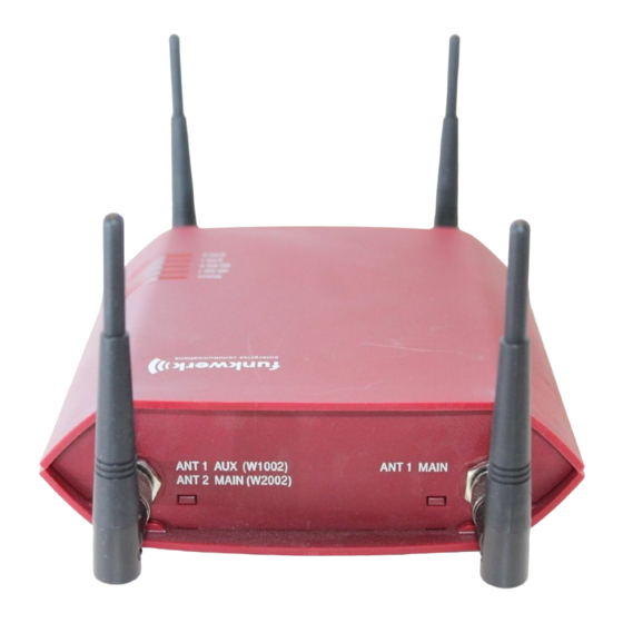
Page 44: Connections
On bintec W2002 the third and fourth antenna connections are located on the underside of the device. bintec W1002 and bintec W2002 have two Ethernet connections and one serial interface. - Page 45 6 Technical data Funkwerk Enterprise Communications GmbH bintec W2002 Fig. 14: underside bintec W1002, bintec W2002 underside POWER Socket for plug-in power pack CONSOLE Serial Interface RESET Reset button ETH1 / ETH2 10/100 Base-T Ethernet interface bintec W2002: Connections for screwing on the external antennas...
-
Page 46: Pin Assignments
6 Technical data Funkwerk Enterprise Communications GmbH RESET Reset button ETH1/PoE and 10/100 Base-T Ethernet interface ETH2 ANT3 Connections for screwing on the external antennas ANT3 = RX3 ANT1/ANT2 Top (Fig.) Connections for screwing on the external antennas ANT1 = TX/RX1 (Connection of first directional antenna) -
Page 47: Frequencies And Channels
6 Technical data Funkwerk Enterprise Communications GmbH Function Eth1 - PoE Function Eth 2 Power Not used RD -/Power RD - Power Not used Power Not used The Ethernet 10/100 BASE-T interface does not have an Auto-MDI-X function. 6.1.5.2 Serial Interface Your device has a Serial interface for connection to a console. -
Page 48: Bintec Wi1040, Wi2040 And Wi3040
6 Technical data Funkwerk Enterprise Communications GmbH 6.2 bintec WI1040, WI2040 and WI3040 6.2.1 Scope of supply Your device is supplied with the following parts: • Cable sets: - Serial cable (D-SUB9) - Ethernet cable (RJ-45, STP) • Self-adhesive feet to allow the device to be used as a desktop device •... -
Page 49: General Product Features
6 Technical data Funkwerk Enterprise Communications GmbH 6.2.2 General Product Features To ensure safe operation, the WI series devices have a connection to earth. The minimum cross-section of the earth lead should be 1.5 mm². The distance between the device and the connection to earth should be as short as possible. - Page 50 6 Technical data Funkwerk Enterprise Communications GmbH Property Value devices must be earthed. 24V DC 1,1A ± 30 % with reverse voltage protec- tion, insulated 3-pole PoE on Ethernet 1 Class 0 (insulated) with max. two WLAN modules Protection against theft...
- Page 51 6 Technical data Funkwerk Enterprise Communications GmbH Property Value Antennas: Antenna connection RTNC socket Transmit Power (WLAN) max. 100 mW (20 dBm) EIRP Receiver sensitivity In the 5 GHz frequency band PER 10 % 6 mbps -90 dBm, 9 mbps -88 dBm,...
- Page 52 6 Technical data Funkwerk Enterprise Communications GmbH Property Value Standards IEEE 802.11a,b,g,d,h,i; IEEE 802.3, IEEE 802.3af, IEEE 802.1q (VLAN Tagging) Standards & Guidelines R&TTE Directive 1999/5/EC EN 60950 (IEC60950); EN 300 328-1/2; ETSI EN 301 489-1/17; EN 60101-1-2 (medicine) e1 e-mark (automotive) LATER)
-
Page 53: Leds
6 Technical data Funkwerk Enterprise Communications GmbH 6.2.3 LEDs By means of the eight LEDs, you can see the wireless status, wireless activity, Ethernet activity and LED states of your device. The LED states are indicated by combinations of the LEDs which are explained in detail in this chapter. -
Page 54: Connections
6 Technical data Funkwerk Enterprise Communications GmbH State Information (2x green) Cable plugged in and link on (flickering) Cable plugged in and link with data traffic SFP (green) No data traffic Data traffic via the SFP interface. on (flickering) Cable plugged in and data traffic During the boot operation, only the red LED is on. -
Page 55: Pin Assignments
6 Technical data Funkwerk Enterprise Communications GmbH 6.2.5 Pin Assignments 6.2.5.1 Ethernet interface Your device has two Ethernet interfaces. These are used to connect individual PCs or other switches. The connection is made via an RJ45 socket. Fig. 21: Ethernet 10/100 Base-T interface (RJ45 socket) -
Page 56: Frequencies And Channels
6 Technical data Funkwerk Enterprise Communications GmbH The pin assignment is as follows: Pin assignment of the Sub-D port Function 6.2.6 Frequencies and channels Different certification regulations apply around the world. ETSI standards generally apply (predominantly used in Europe). For operation in Europe, please read the notes in the R&TTE Compliance Information. -
Page 57: General Product Features
6 Technical data Funkwerk Enterprise Communications GmbH • Antennas: - 2 external standard antennas to be screwed on (for bintec WI1065) - 4 external standard antennas to be screwed on (for bintec WI 2065 and WI 3065) • CD • Documentation:... - Page 58 6 Technical data Funkwerk Enterprise Communications GmbH Property Value SFP) Power consumption of the device 5-15 Watt, depending on extensions Voltage supply Earth conductor/connection to earth M4. All devices must be earthed. 24V DC 1,1A ± 30 % with reverse voltage protec- tion, insulated 3-pole PoE on Ethernet 1 Class 0 (insulated) with max.
- Page 59 6 Technical data Funkwerk Enterprise Communications GmbH Property Value Ethernet interface RJ45 socket Antennas: Antenna connection RTNC socket Transmit Power (WLAN) max. 100 mW (20 dBm) EIRP Receiver sensitivity In the 5 GHz frequency band PER 10 % 6 mbps -90 dBm, 9 mbps -88 dBm,...
- Page 60 6 Technical data Funkwerk Enterprise Communications GmbH Property Value Standards IEEE 802.11a,b,g,d,h,i; IEEE 802.3, IEEE 802.3af, IEEE 802.1q (VLAN Tagging) Standards & Guidelines R&TTE Directive 1999/5/EC EN 60950 (IEC60950); EN 300 328-1/2; ETSI EN 301 489-1/17; EN 60101-1-2 (medicine) e1 e-mark (automotive) LATER)
-
Page 61: Leds
6 Technical data Funkwerk Enterprise Communications GmbH 6.3.3 LEDs By means of the eight LEDs, you can see the wireless status, wireless activity, Ethernet activity and LED states of your device. The LED states are indicated by combinations of the LEDs which are explained in detail in this chapter. -
Page 62: Connections
6 Technical data Funkwerk Enterprise Communications GmbH State Information Cable plugged in and link on (flickering) Cable plugged in and link with data traffic SFP (green) No data traffic Data traffic via the SFP interface. on (flickering) Cable plugged in and data traffic During the boot operation, only the red LED is on. - Page 63 6 Technical data Funkwerk Enterprise Communications GmbH 6.3.5.1 Ethernet interface Your device has two Ethernet interfaces. These are used to connect individual PCs or other switches. The connection is made via an RJ45 socket. Fig. 25: Ethernet 10/100 Base-T interface (RJ45 socket)
-
Page 64: Frequencies And Channels
6 Technical data Funkwerk Enterprise Communications GmbH Pin assignment of the Sub-D port Function 6.3.6 Frequencies and channels Different certification regulations apply around the world. ETSI standards generally apply (predominantly used in Europe). For operation in Europe, please read the notes in the R&TTE Compliance Information. -
Page 65: Chapter 7 Access And Configuration
With a current web browser, you can use the HTML interfaces to configure your device. The configuration can be set up using the Funkwerk Configuration Interface . To do this, enter the IP address of your device in the address field of your Web browser. - Page 66 7 Access and configuration Funkwerk Enterprise Communications GmbH You do not need any additional software on your PC to set up a Telnet connection to your device. Telnet is available on all operating systems. Proceed as follows: Windows (1) Click Run… in the Windows Start menu.
- Page 67 7 Access and configuration Funkwerk Enterprise Communications GmbH connect to the device via SSH: Flash-Sh > ls -al Flags Version Length Date Name ... Vr-xpbc-B 7.1.04 2994754 2004/09/02 14:11:48 box150_srel.ppc860 Vrw-pl--f 0.0 350 2004/09/07 10:44:14 sshd_host_rsa_key.pub Vrw-pl--f 0.0 1011 2004/09/07 10:44:12 sshd_host_rsa_key Vrw-pl--f 0.0.01 730 2004/09/07 10:42:17 sshd_host_dsa_key.pub...
-
Page 68: Access Via The Serial Interface
7 Access and configuration Funkwerk Enterprise Communications GmbH (1) Enter ssh <IP address of the device> in a terminal. The login prompt window appears. This is located in the SNMP shell of the device. (2) Continue with Logging in on page 57. -
Page 69: Logging In
7 Access and configuration Funkwerk Enterprise Communications GmbH Check If the login prompt does not appear after you press Return several times, the connection to your device has not been set up successfully. Therefore, check the COM1 or COM2 settings on your PC. -
Page 70: User Names And Passwords In Ex Works State
In its ex works state, your device is provided with the following user names and passwords: User names and passwords in ex works state User name Password Authorisations funkwerk Read and change system variables, store configurations; use admin Funkwerk Configuration Interface and Setup Tool. Read and write system variables (except passwords) (changes... -
Page 71: Configuration Options
(1) Enter your user name e.g. admin, and confirm with Return. (2) Enter your user password e.g. funkwerk, and confirm with Return. Your device logs in with the input prompt, e.g. w1002:>. The login was successful. You are now in the SNMP shell. -
Page 72: Funkwerk Configuration Interface For Advanced Users
7.3.1 Funkwerk Configuration Interface for advanced users The Funkwerk Configuration Interface is a web-based graphic user surface that you can use from any PC with an up-to-date web browser via an HTTP or HTTPS connection. You can use the Funkwerk Configuration Interface to carry out all configuration tasks easily. - Page 73 7 Access and configuration Funkwerk Enterprise Communications GmbH Funkwerk Configuration Interface Fig. 27: Initial Screen bintec W1002/W1002n/W2002/WIx040/WIx065...
- Page 74 DHCP server or the address statically assigned by you with the ComPoint Manager) in the Web browser's address field. (5) Enter admin in the User field and funkwerk in the Password field and click LOGIN. You are not in the status menu of your device's Funkwerk Configuration Interface (see State on page 83).
- Page 75 Function Language selection: From the dropdown menu, select the lan- guage in which the Funkwerk Configuration Interface is to be displayed. Here, you can select the language in which you want to carry out the configuration. German and English are avail- able.
- Page 76 You can see at a glance the sub-menu you are in. Status page If you call the Funkwerk Configuration Interface , after you log in the status page of your device is displayed. The most important data of your device can be seen on this at a glance.
- Page 77 7 Access and configuration Funkwerk Enterprise Communications GmbH Configuration elements The various actions that you can perform when configuring your device in the Funkwerk Configuration are triggered by means of the following buttons: Funkwerk Configuration Interface buttons Button Function Updates the view.
- Page 78 Triggers a WLAN bandscan. Displays the next page in a list. Displays the previous page in a list. You can select the following operating functions in the list view: Funkwerk Configuration Interface list options Menu Function Update Interval Here you can set the interval in which the view is to be updated.
- Page 79 Fig. 32: Configuration of the update interval Fig. 33: Filter list Structure of the Funkwerk Configuration Interface configuration menus The menus of the Funkwerk Configuration Interface contain the following basic struc- tures: Funkwerk Configuration Interface menu structure Menu...
- Page 80 Funkwerk Enterprise Communications GmbH Menu Function Menu Click this tab to display extended configuration options. The following options are available for the configuration: Funkwerk Configuration Interface configuration elements Menu Function Input fields e.g. empty text field Text field with hidden input Enter the data.
- Page 81 Pay particular attention to the following message: "Warning: changes not supported by the Setup Tool!". If you makes these changes with the Funkwerk Configuration Interface , this can cause inconsistencies or mal- functions. Therefore, it is recommended that the configuration is continued with the Setup Tool.
- Page 82 7 Access and configuration Funkwerk Enterprise Communications GmbH Menu Function This information includes serial number, software version, cur- rent memory and processor use, status of the physical inter- faces and the last 10 system messages. Global Settings In this menu, you enter the basic system settings of your device, such as, for example, system name, system date, system time and passwords.
- Page 83 7 Access and configuration Funkwerk Enterprise Communications GmbH Menu Function WLANx In this menu, you configure your wireless modules as an access point or bridge. Administration In this menu, you make the basic WLAN settings. Routing Menu Function Routes In this menu, you enter additional routes.
- Page 84 7 Access and configuration Funkwerk Enterprise Communications GmbH Firewall Menu Function Policies In this menu you configure the filter rules for the firewall. Interfaces In this menu, you can group together the interfaces to be filtered. Addresses In this menu, you can create the address aliases to be filtered.
-
Page 85: The Setup Tool For Experts
7 Access and configuration Funkwerk Enterprise Communications GmbH External Reporting Menu Function Syslog In this menu, you configure the host to which the data logged in- ternally on the device is forwarded for saving and further pro- cessing. IP Accounting In this menu, you decide for which interfaces accounting mes- sages are to be generated. - Page 86 7 Access and configuration Funkwerk Enterprise Communications GmbH Proceed as follows to start a Setup Tool session: (1) Log in to your device as admin (see Logging in for Configuration on page 58). (2) Enter setup after the input prompt and press Return.
- Page 87 7 Access and configuration Funkwerk Enterprise Communications GmbH Key combination Meaning Tabulator Jump to the next menu field. Return key Open sub-menu or activate command (e.g. SAVE). up or down (arrow keys) Go to the next or previous field in the menu (works with VT 100 emulation when using a terminal program).
- Page 88 7 Access and configuration Funkwerk Enterprise Communications GmbH Button Meaning SAVE Save all the entries of the current menu and all the sub-menus in the working memory. These changes become effective imme- diately. EXIT Leave the current menu and return to the main menu. Any entries made are lost.
- Page 89 7 Access and configuration Funkwerk Enterprise Communications GmbH (2) If necessary, enter more characters to refine the search. (3) The Backspace or Delete key can be used to edit the search string. The cursor automatically jumps to the first match it finds with the corresponding initial let- ters.
- Page 90 7 Access and configuration Funkwerk Enterprise Communications GmbH (1) Select the password field in the desired menu and enter the new password. (2) The field changes to the change mode and the message Change Password appears in the help line.
- Page 91 7 Access and configuration Funkwerk Enterprise Communications GmbH Fig. 37: Setup Tool menu structure To help you when making the configuration settings, the menus are briefly explained below: Setup Tool menus Menu Function Licenses In this menu, you can manage licences that are needed for us- ing certain functions.
-
Page 92: Snmp Shell
7 Access and configuration Funkwerk Enterprise Communications GmbH Menu Function Service Provider (ISP). All the WAN partners entered are dis- played in a list that includes the name of partner, protocol used and current status. Security In this menu, you configure the security features of your device, e.g. -
Page 93: Bootmonitor
7 Access and configuration Funkwerk Enterprise Communications GmbH 7.4 BOOTmonitor The BOOTmonitor is only available over a serial connection to the device. The BOOTmonitor provides the following functions, which you select by entering the cor- responding number: (1) Boot System (reboot the system): The device loads the compressed boot file from the flash memory to the working memory. - Page 94 7 Access and configuration Funkwerk Enterprise Communications GmbH Fig. 38: BOOTmonitor After display of the BOOTmonitor prompt, press the space bar within four seconds to use the functions of the BOOTmonitor. If you do not make an entry within four seconds, the device changes back to normal operating mode.
-
Page 95: Chapter 8 System Management
8.1 State If you log into the Funkwerk Configuration Interface , your device's status page is dis- played, which shows the most important system information. You see an overview of the following data: •... - Page 96 8 System management Funkwerk Enterprise Communications GmbH System Management Status Fig. 39: -> The System Management -> Status menu consists of the following fields: Fields in the Status System Information menu Field Value Uptime Displays the time past since the device was rebooted.
- Page 97 8 System management Funkwerk Enterprise Communications GmbH Field Value CPU Usage Displays the CPU usage as a percentage. Memory Usage Displays the usage of the working memory in MByte in relation to the available total working memory in MByte. The usage is also displayed in brackets as a percentage.
-
Page 98: Global Settings
8 System management Funkwerk Enterprise Communications GmbH Field Value Access Client Mode: • Operation Mode: Access Client or Off • The channel used on this wireless module • Software version of the wireless card Bridge mode: • Operation Mode: Bridge or Off •... - Page 99 Enter the relevant contact person. Here you can enter the e- mail address of the system administrator, for example. A character string of up to 255 characters is possible. The default value is FUNKWERK. Maximum Number of Enter the maximum number of syslog messages that are stored Syslog Entries internally in the device.
-
Page 100: Passwords
8 System management Funkwerk Enterprise Communications GmbH Field Value The default value is 20. You can view the stored messages in Monitoring ->Internal Log. Maximum Message Select the priority of system messages above which a log Level of Syslog Entries should be created. - Page 101 8 System management Funkwerk Enterprise Communications GmbH System Management Global Settings Passwords Fig. 41: -> -> Note All bintec devices are delivered with the same username and password. As long as the password remains unchanged, they are not protected against unauthorised use.
-
Page 102: Date And Time
8 System management Funkwerk Enterprise Communications GmbH Field Value SNMP Read Community Enter the password for the user name read. SNMP Write Community Enter the password for the user name write. Fields in the Passwords Global Password Options menu Field... - Page 103 8 System management Funkwerk Enterprise Communications GmbH System Management Global Settings Date and Time Fig. 42: -> -> You have the following options for determining the system time: • You can determine the system time automatically, e.g. using various time servers. To en- sure that the device uses the desired current time, you should configure one or more time servers.
- Page 104 8 System management Funkwerk Enterprise Communications GmbH Fields in the Date and Time Manual Time Settings menu Field Description New Date Enter a new date. Format: • Day: dd • Month: mm • Year: yyyy New Time Enter a new time.
- Page 105 8 System management Funkwerk Enterprise Communications GmbH Field Description time protocol with UDP port 123. • Time Service / UDP: This server uses the Time service with UDP port 37. • Time Service / TCP: This server uses the Time service with TCP port 37.
-
Page 106: System Licences
8 System management Funkwerk Enterprise Communications GmbH Field Description • Aggressive: For ten minutes, the system attempts to con- tact the time server after 1, 2, 4, 8 seconds, and then every 10 seconds. • Endless: For an unrestricted period, the system attempts to contact the time server after 1, 2, 4, 8 seconds, and then every 10 seconds. - Page 107 8 System management Funkwerk Enterprise Communications GmbH • License Key and • Licence Serial Number You enter this data in the System Management -> Global Settings->System Licenses->New menu. In the System Management ->Global Settings->System Licenses menu, a list of all re- gistered licenses is shown (Description, License Type, License Serial Number, Status).
-
Page 108: Interface Mode / Bridge Groups
8 System management Funkwerk Enterprise Communications GmbH agement -> Global Settings -> System Licenses -> New menu. The System Management->Global Settings->System Licenses->New menu consists of the following fields: Fields in the System LicencesBasic Parameters menu Field Value Licence Serial Number Enter the licence serial number you received when you bought the licence. - Page 109 8 System management Funkwerk Enterprise Communications GmbH in the data packets is not interpreted. Conventions for port/interface names The names of wireless ports in the user interface of your device are made up of the follow- ing parts: (a) WLAN...
-
Page 110: Interfaces
8 System management Funkwerk Enterprise Communications GmbH (b) Number of the wireless module on which the WDS link or bridge link is configured (c) Number of the WDS link or bridge link Example: wds1-0 (first WDS link or bridge link on the first wireless module) - Page 111 8 System management Funkwerk Enterprise Communications GmbH System Management Interface Mode / Bridge Groups Interfaces Fig. 44: -> -> The System Management -> Interface Mode / Bridge Groups ->Interfaces menu con- sists of the following fields: Fields in the Interfaces menu...
- Page 112 8 System management Funkwerk Enterprise Communications GmbH Field Description the group's IP address when it is taken out of the group. 8.3.1.1 <stax-x> Edit Click the icon to edit additional settings for WLAN clients in bridge mode (so-called MAC bridge).
- Page 113 8 System management Funkwerk Enterprise Communications GmbH The System Management->Global Settings->Interface Mode / Bridge Groups-> Edit menu consists of the following fields: Fields in the <stax-x> Layer 2.5 Option menu Field Value Interface Shows the interface that is being edited.
-
Page 114: Administrative Access
8 System management Funkwerk Enterprise Communications GmbH Field Value The function is disabled by default. 8.4 Administrative Access In this menu, you can configure the administrative access to the device. 8.4.1 Access In the Administrative Access -> Access menu, a list of all physical interfaces is shown. -
Page 115: Ssh
8 System management Funkwerk Enterprise Communications GmbH 8.4.1.1 Add Click the Add button to add more interfaces. System Management Administrative Access Access Fig. 47: -> -> -> The System Management -> Administrative Access -> Access -> Add menu consists of... - Page 116 8 System management Funkwerk Enterprise Communications GmbH System Management Administrative Access Fig. 48: -> -> You need an SSH client application, e.g. PuTTY, to be able to reach the SSH Daemon. If you wish to use SSH Login together with the PuTTY client, you may need to comply with some special configuration requirements, for which we have prepared FAQs.
- Page 117 8 System management Funkwerk Enterprise Communications GmbH Field Value Compression Select whether data compression should be used. The function is activated by choosing Enabled. The function is disabled by default. TCP Keepalives Select whether the device is to send keepalive packets.
- Page 118 8 System management Funkwerk Enterprise Communications GmbH Field Value • MD5 • SHA-1 • RipeMD 160 MD5, SHA-1 and RipeMD160 are enabled by default. Fields in the SSH Key Status menu Field Value RSA Key Status The status of the RSA key is displayed here.
-
Page 119: Snmp
8 System management Funkwerk Enterprise Communications GmbH 8.4.3 SNMP SNMP (Simple Network Management Protocol) is a network protocol used to monitor and control network elements (e.g. routers, servers, switches, printers, computers etc.) from a central station. SNMP controls communication between the monitored devices and monit- oring station. -
Page 120: Remote Authentication
8 System management Funkwerk Enterprise Communications GmbH Field Value SNMP Version Select the SNMP version your device is to use to listen for ex- ternal SNMP accesses. Possible values: • v1: SNMP Version 1 • v2c: Community-Based SNMP Version 2 •... - Page 121 8 System management Funkwerk Enterprise Communications GmbH For an incoming connection, your device sends a request with user name and password to the RADIUS server, which then searches its database. If the user is found and can be au- thenticated, the RADIUS server sends corresponding confirmation to your device. This con- firmation also contains parameters (called RADIUS attributes), which your device uses as WAN connection parameters.
- Page 122 8 System management Funkwerk Enterprise Communications GmbH Field Value ACCOUNTING_STOP Client -> Server If a RADIUS server is used for accounting, your device sends an accounting message to the RADIUS server at the end of each connection. In the System Management -> Remote Authentication -> RADIUS menu, a list of all re- gistered RADIUS servers is displayed.
- Page 123 8 System management Funkwerk Enterprise Communications GmbH Field Value Authentication Type Select what the RADIUS server is to be used for. Possible values: • Authentication (default value): The RADIUS server is used for controlling access to a network. • PPP Accounting: The RADIUS server is used for recording statistical call data.
- Page 124 8 System management Funkwerk Enterprise Communications GmbH Field Value quest is received. Possible values: • Authoritative (default value): A negative answer to a re- quest is accepted. • Non-authoritative : A negative answer to a request is not accepted. A request is sent to the next RADIUS server until your device receives an answer from a server configured as authoritative.
-
Page 125: Tacacs
8 System management Funkwerk Enterprise Communications GmbH Field Value to a request. If an answer has still not been received after these attempts, the Status is set to down. If the Active Check = En- abledyour device tries to reach the server every 20 seconds. If the server answers, the Status is set back to alive. - Page 126 8 System management Funkwerk Enterprise Communications GmbH TACACS+ uses TCP port 49 and establishes a secure and encrypted connection. In the System Management -> Remote Authentication -> TACACS+ menu, a list of all registered TACACS+ servers is displayed. 8.5.2.1 Edit/New Choose the icon to edit existing entries.
- Page 127 8 System management Funkwerk Enterprise Communications GmbH Field Description Server IP Address Enter the IP address of the TACACS+ server that is to be re- quested for login authentication. TACACS+ Secret Enter the password to be used to authenticate and, if applic- able, encrypt data exchange between the TACACS+ server and the network access server (your device).
-
Page 128: Options
8 System management Funkwerk Enterprise Communications GmbH Field Description If a response is not received during the wait time, the next con- figured TACACS+ server is queried (only if Policy = Non- authoritative) and the current server is set to status Blocked. - Page 129 8 System management Funkwerk Enterprise Communications GmbH System Management Remote Authentication Options Fig. 52: -> -> The System Management -> Remote Authentication -> Options menu consists of the following fields: Fields in the Options Global RADIUS options menu Field Description...
-
Page 130: Chapter 9 Physical Interfaces
9 Physical interfaces Funkwerk Enterprise Communications GmbH Chapter 9 Physical interfaces 9.1 Ethernet Ports An Ethernet interface is a physical interface for connection to the local network or external networks. Note In the ex works state, the Ethernet ports ETH1 and ETH2 are assigned to the standard bridge group br0, which is configured as DHCP client and with the fallback IP ad- dress 192.168.0.252 and Netmask 255.255.255.0. -
Page 131: Serial Port
9 Physical interfaces Funkwerk Enterprise Communications GmbH Field Description numbering of the Ethernet ports on the back of the device. Interface Displays the interface assigned to the Ethernet port here. Configured Speed / Select the mode in which the interface is to run. -
Page 132: Serial Port
9 Physical interfaces Funkwerk Enterprise Communications GmbH 9.2.1 Serial Port You can make settings for the serial interface in the Physical Interfaces->Serial Port->Serial Port menu. Physical Interfaces Serial Port Serial Port Fig. 54: -> -> The Physical Interfaces->Serial Port->Serial Port menu consists of the following fields:... - Page 133 9 Physical interfaces Funkwerk Enterprise Communications GmbH Physical Interfaces Serial Port Serial Port Port Mode Fig. 55: -> -> with Data Port Fields in the Serial PortSerial Settings menu Field Description Baud rate Select which baud rate should be used. Make sure that the re- mote terminal is suitable for the selected baud rate.
- Page 134 9 Physical interfaces Funkwerk Enterprise Communications GmbH Field Description • 19200 • 57600 • 115200 Data bits Select how many data bits should be sent in sequence for traffic data. Possible values: • 8 (default value): Eight data bits are sent in sequence.
- Page 135 9 Physical interfaces Funkwerk Enterprise Communications GmbH Field Description flow over the RTS and CTS lines. • XON/XOFF: If the software handshake is used, the recipient sends special signs to the sender to control the data flow. Fields in the Serial PortIP menu...
-
Page 136: Relay
9 Physical interfaces Funkwerk Enterprise Communications GmbH Field Description The function is enabled by default. Possible values: 0 65535. Default value: 0. Inter-ByteGap Enter the time in ms since receiving the first character, which is used as a trigger for data transmission. -
Page 137: Relay Configuration
9 Physical interfaces Funkwerk Enterprise Communications GmbH 9.3.1 Relay configuration In this menu, you can configure the port mode. Physical Interfaces Relay Relay Configuration Fig. 56: -> -> The Physical Interfaces->Relay->Relay Configuration menu consists of the following fields: Fields in the Relay ConfigurationBasic Parameters menu... -
Page 138: Chapter 10 Lan
10 LAN Funkwerk Enterprise Communications GmbH Chapter 10 LAN In this menu, you configure the addresses in your LAN and can structure your local network using VLANs. 10.1 IP configuration The IP configuration of the bridge groups can be edited in this menu. - Page 139 10 LAN Funkwerk Enterprise Communications GmbH device will no longer obtain an IP configuration dynamically over DHCP. Example of subnets If your device is connected to a LAN that consists of two subnets, you should enter a second IP / Netmask.
- Page 140 10 LAN Funkwerk Enterprise Communications GmbH Field Description Based on Ethernet Inter- This field is only displayed if you are editing a virtual routing in- face terface. Select the Ethernet interface for which the virtual interface is to be configured.
- Page 141 10 LAN Funkwerk Enterprise Communications GmbH Field Description Possible values are 2 (default value) to 4094. The Advanced Settingsmenu consists of the following fields: Fields in the menu Advanced Settings Field Description DHCP MAC Address Only if Address Mode = DHCP If Use Built-In is activated (default setting), the hardware MAC address of the Ethernet interface is used.
-
Page 142: Vlan
10 LAN Funkwerk Enterprise Communications GmbH 10.2 VLAN By implementing VLAN segmentation in accordance with 802.1Q, you can configure VLANs on your device. The wireless ports of an access point, in particular, are able to re- move the VLAN tag of a frame sent to the clients and to tag received frames with a pre- defined VLAN ID. -
Page 143: Vlans
10 LAN Funkwerk Enterprise Communications GmbH Caution For interfaces that operate in Routing mode, you only assign a VLAN ID to the inter- face. You define this via the parameter Interface Mode = VLAN and the VLAN ID field in the LAN -> IP Configuration ->Interfaces->New menu. -
Page 144: Port Configuration
10 LAN Funkwerk Enterprise Communications GmbH Field Description VLAN Name Enter a unique name for the VLAN. A character string of up to 32 characters is possible. VLAN Members Select the ports that are to belong to this VLAN. You can use the Add button to add members. -
Page 145: Administration
10 LAN Funkwerk Enterprise Communications GmbH Field Description If a packet without a VLAN tag reaches this port, it is assigned this PVID. Drop untagged frames If this option is enabled, untagged frames are discarded. If the option is disabled, untagged frames are tagged with the PVID defined in this menu. - Page 146 10 LAN Funkwerk Enterprise Communications GmbH Field Description Management VID Enter the VLAN ID of the VLAN in which your device is to oper- ate. bintec W1002/W1002n/W2002/WIx040/WIx065...
-
Page 147: Chapter 11 Wireless Lan
11 Wireless LAN Funkwerk Enterprise Communications GmbH Chapter 11 Wireless LAN In the case of wireless LAN (WLAN = Wireless Local Area Network), this relates to the cre- ation of a network using wireless technology. Network functions Like a wired network, a WLAN offers all the main network functions. Access to servers, files, printers, and the e-mail system is just as reliable as company-wide Internet access. -
Page 148: Wlanx
11 Wireless LAN Funkwerk Enterprise Communications GmbH An amendment to the Telecommunications Act (TKG) allowed the 5.8 GHz band (5755 MHz - 5875 MHz) to be used for so-called BFWA applications (Broadband Fixed Wireless Access). This simply requires registration with the Federal Network Agency. However, the use of TPC and DFS is mandatory in this case. - Page 149 11 Wireless LAN Funkwerk Enterprise Communications GmbH Wireless LAN WLANx Radio Settings Fig. 63: -> -> -> bintec W1002/W1002n/W2002/WIx040/WIx065...
- Page 150 11 Wireless LAN Funkwerk Enterprise Communications GmbH Wireless LAN WLANx Radio Settings bintec W1002n Fig. 64: bintec W1002/W1002n/W2002/WIx040/WIx065...
- Page 151 11 Wireless LAN Funkwerk Enterprise Communications GmbH Wireless LAN WLANx Radio Settings Operation Mode Fig. 65: Access Client The Wireless LAN -> WLANx -> Radio Settings -> menu consists of the following fields: Fields in the Radio Settings WLAN Settings menu...
- Page 152 11 Wireless LAN Funkwerk Enterprise Communications GmbH Field Description • Access Client: Your device serves as an Access Client in your network. • Bridge: Your device is used as a wireless bridge in your net- work. Client mode Only for Operating Mode = Access Client Possible values: •...
- Page 153 11 Wireless LAN Funkwerk Enterprise Communications GmbH Field Description For Operation Mode = Access Client Possible values: • 2.4 and 5 GHz(default value) • 5 GHz • 2.4 GHz Usage Area Only for Operation Mode = Access Client, Client Mode = Infrastructure and Operation Band = 2.4 and 5 GHz, 5...
- Page 154 11 Wireless LAN Funkwerk Enterprise Communications GmbH Field Description Possible values: • For Operation Band = 2.4 GHz In/Outdoor Possible values are 1 to 13 and Auto (default value). • For Operation Band = 5 GHz Indoor Possible values are 36, 40, 44, 48 and Auto (default value) •...
- Page 155 • 2 (default value): Two traffic flows are used. • 1: One traffic flow is used. Antenna Diversity Only for bintec W1002, bintec W2002, bintec WIx040, bintec WIx060 Select how many and which antennas are used to send and re- ceive.
- Page 156 Field Description Wireless Mode Select the wireless technology that the access point is to use. For bintec W1002, bintec W2002, bintec WIx040, bintec WIx060 Only for Operation Band = 2.4 GHz In/Outdoor Possible values: • 802.11g: The device operates only in accordance with 802.11g.
- Page 157 11 Wireless LAN Funkwerk Enterprise Communications GmbH Field Description Only a data rate of 1 and 2 mbps needs to be supported by all clients (basic rates). This mode is also needed for Centrino clients if connection problems occur. • 802.11 mixed-short: Your device adapts to the client technology and operates according to either 802.11b or...
- Page 158 Operation Band, Bandwidth, Number of Spatial Streams and Wireless Mode. Nitro Mode Only for bintec W1002, bintec W2002, bintec WIx040, bintec WIx060 Activate this function to increase the transmission speed for 802.11g through frame bursting. As a result, several packets are sent one after the other without a waiting period.
- Page 159 11 Wireless LAN Funkwerk Enterprise Communications GmbH Field Description • Frame Compression: If this function is activated, sent data is compressed. This only works in combination with clients that use Conexant radio cards. The gain in transmission speed depends to a large extent on the type of transmitted data.
- Page 160 11 Wireless LAN Funkwerk Enterprise Communications GmbH Field Description beacons. This value is transmitted in Beacon and Probe Response Frames. Possible values are 1 to 65535. The default value is 100 msec. DTIM Period Only for Operation Mode = Access Point.
- Page 161 11 Wireless LAN Funkwerk Enterprise Communications GmbH Field Description Possible values are 1 to 255. The default value is 7. Long Retry Limit Enter the maximum number of attempts to send a data packet of length less than or equal to the value defined in RTS Threshold.
- Page 162 11 Wireless LAN Funkwerk Enterprise Communications GmbH Field Description The default value is 1023. Max Receive Lifetime Not for bintec W1002n Enter the time from receipt of the first fragment of a data packet as of which no further attempts are made. The data packet is discarded.
- Page 163 11 Wireless LAN Funkwerk Enterprise Communications GmbH Field Description radio connection becomes unsuitable for higher data rates. • Normal Roaming (default value): Standard roaming. • Slow Roaming: The WLAN client searches for available wireless networks as soon as the radio signal of the existing radio connection becomes weaker.
- Page 164 11 Wireless LAN Funkwerk Enterprise Communications GmbH Field Description The value can only be changed for Roaming Profile = Custom Roaming. The default value is 20 ms. Indicates the maximum time in milliseconds a frequency is act- Max. Time Period for ively scanned.
- Page 165 11 Wireless LAN Funkwerk Enterprise Communications GmbH Field Description Enable this function to reduce the guard interval (= time between transmission of two data symbols) from 800ns to 400ns. Short Retry Limit Enter the maximum number of attempts to send a frame of length less than or equal to the value defined in RTS Threshold.
-
Page 166: Virtual Service Sets
11 Wireless LAN Funkwerk Enterprise Communications GmbH Field Description Possible values are 1 to 65535. The default value is 15. CW Max. Not for bintec W1002n Here, you can define the minimum size of the contention win- dow. Possible values are 1 to 65535. - Page 167 11 Wireless LAN Funkwerk Enterprise Communications GmbH work has a parameter that uniquely identifies the network and is comparable with a domain name. Only clients with a network configuration that matches that of your device can com- municate in this WLAN. The corresponding parameter is called the network name. In the network environment, it is sometimes also referred to as the SSID.
- Page 168 • Change the access passwords for your device. • Change the default SSID, Network Name (SSID) = Funkwerk-ec , of your access point. Set Visible = Enabled. This will exclude all WLAN clients that attempt to establish a connection with the general value for Network Name (SSID) Any and do not know the SSID settings.
- Page 169 11 Wireless LAN Funkwerk Enterprise Communications GmbH 11.1.2.1 -> Virtual Service Sets New/ Choose the icon to edit existing entries. Choose the New button to configure other wire- less networks. Wireless LAN WLANx Virtual Service Sets /New Fig. 66: ->...
- Page 170 11 Wireless LAN Funkwerk Enterprise Communications GmbH Field Description The function is enabled by default. ARP Processing Select whether the ARP processing function should be enabled. The ARP data traffic is reduced in the network by the fact that ARP broadcasts that have been converted to ARP unicasts are forwarded to IP addresses that are known internally.
- Page 171 Enter a character string with the right number of characters for the selected WEP mode. For WEP 40 you need a string of 5 characters, WEP 104 13 characters. For example hello for WEP 40, funkwerk-wep1 for WEP 104. WPA Mode Only if Security Mode = WPA-PSK and WPA-Enterprise Select whether you want to use WPA (with TKIP encryption) or WPA 2 (with AES encryption), or both.
-
Page 172: Wds Links
11 Wireless LAN Funkwerk Enterprise Communications GmbH Field Description Select which encryption method should be used. Possible values: • TKIP (default value): Temporal Key Integrity Protocol. • AES: Advanced Encryption Standard. • AES and TKIP Both encryption methods are rated as secure, with AES offering better performance. - Page 173 11 Wireless LAN Funkwerk Enterprise Communications GmbH the data sheet for your device. WDS links (WDS = Wireless Distribution System) are static links between access points (AP), which are generally used to connect clients with networks that are not directly ac- cessible to them e.g.
- Page 174 11 Wireless LAN Funkwerk Enterprise Communications GmbH fields: Fields in the WDS LinksBasic Parameters menu Field Description WDS description Enter a name for the WDS link. If the Use Standard option is activated, the generated name of the interface is automatically used.
-
Page 175: Client Link
11 Wireless LAN Funkwerk Enterprise Communications GmbH Field Description If the entry starts with 0x, the generator is deactivated. Enter a hexadecimal string with exactly the right number of charac- ters for the selected WEP mode. 10 characters for WEP40 or 26 characters for WEP104 e.g. - Page 176 11 Wireless LAN Funkwerk Enterprise Communications GmbH 11.1.4.1 -> Client Links Choose the icon to edit existing entries. Wireless LAN WLANx Client Link Fig. 68: -> -> -> -> The Wireless LAN->WLANx->Client Link-> -> menu consists of the following fields:...
- Page 177 Enter a character string with the right number of characters for the selected WEP mode. For WEP 40 you need a string of 5 characters, WEP 104 13 characters. For example hello for WEP 40, funkwerk-wep1 for WEP 104. WPA Mode Only if Security Mode = WPA-PSK and WPA-Enterprise Select whether you want to use WPA (with TKIP encryption) or WPA 2 (with AES encryption), or both.
- Page 178 11 Wireless LAN Funkwerk Enterprise Communications GmbH Field Description WPA2 Cipher Only for Security Mode = WPA-PSK and WPA Mode = WPA2 Select which encryption method should be used. Possible values: • TKIP (default value): Temporal Key Integrity Protocol. • AES: Advanced Encryption Standard.
-
Page 179: Bridge Links
Always use the antennas and antenna cables supplied with the equipment to prevent unintentional violations of the applicable law. If you have special requirements, e.g. re- garding cable lengths, please contact your dealer or Funkwerk Enterprise Communica- tions GmbH. bintec W1002/W1002n/W2002/WIx040/WIx065... - Page 180 11 Wireless LAN Funkwerk Enterprise Communications GmbH Bridges are generally used to interconnect various LAN segments at Layer 2 of the OSI 7-layer model. The special feature of bintec bridges is that the distances between these segments can be several kilometres, without the necessity for a cable for these ranges.
- Page 181 11 Wireless LAN Funkwerk Enterprise Communications GmbH Fig. 71: Point-to-multipoint topology Fig. 72: Wireless backbone bintec W1002/W1002n/W2002/WIx040/WIx065...
- Page 182 11 Wireless LAN Funkwerk Enterprise Communications GmbH Fig. 73: Wireless bridge with connection of wireless clients To be able to set up a wireless link to bintec bridges, an uninterrupted view must exist between the antennas at both ends. This is called a line of sight, abbreviated to LOS.
- Page 183 11 Wireless LAN Funkwerk Enterprise Communications GmbH Distance from transmit an- Radius of 1st Fresnel zone Radius at 60 % of tenna (km) 1st Fresnel zone (m) 0,250 0,500 0,750 1,000 1,250 10,7 1,500 11,3 1,750 11,8 2,000 12,1 2,250...
- Page 184 11 Wireless LAN Funkwerk Enterprise Communications GmbH Note When setting up a bridge link, make sure that no obstacles or trees protrude into the Fresnel zone. If obstacles exist, the transmission rate will drop and the path may even- tually fail.
- Page 185 11 Wireless LAN Funkwerk Enterprise Communications GmbH Wireless LAN WLANx Bridge Links /New Fig. 76: -> -> -> -> The Wireless LAN->WLANx->Bridge Links-> ->/New menu consists of the following fields: Fields in the Bridge LinksBasic Parameters menu Field Description Bridge link description Enter a name for the bridge link.
- Page 186 11 Wireless LAN Funkwerk Enterprise Communications GmbH Field Description Privacy Select whether an encryption method is to be used for this bridge link and if so, which one. Possible values: • TKIP (default value): Temporal Key Integrity Protocol. • AES: Advanced Encryption Standard.
- Page 187 11 Wireless LAN Funkwerk Enterprise Communications GmbH After successful scanning, a selection of potential bridge partners is displayed in the scan list. In the Action column, click on [Connect] to connect the local bridge with this bridge. If the partners are connected with one another, the icon appears in the Connected column.
-
Page 188: Administration
11 Wireless LAN Funkwerk Enterprise Communications GmbH 11.2 Administration The Wireless LAN -> Administration menu contains basic settings for running your gate- way as an access point (AP). 11.2.1 Basic settings Wireless LAN Administration Basic Settings Fig. 78: -> ->... -
Page 189: Chapter 12 Routing
12 Routing Funkwerk Enterprise Communications GmbH Chapter 12 Routing 12.1 Routes 12.1.1 IP routes In the Routing -> Routes -> IP Routes menu a list of all configured routes is shown. 12.1.1.1 New Choose the New button to create routes. - Page 190 12 Routing Funkwerk Enterprise Communications GmbH Routing Routes IP Routes Extended Route Fig. 80: -> -> -> with Activated The Routing->Routes->IP Routes->New menu consists of the following fields: Fields in the IP Routes Route Class menu Field Description Extended Route Select whether the route is to be defined with extended para- meters.
- Page 191 12 Routing Funkwerk Enterprise Communications GmbH Field Description Possible values: • Network Route (default value): Route to a network. • Default Route : Is used if no other suitable route is avail- able. • Host Route : Route to a single host.
- Page 192 12 Routing Funkwerk Enterprise Communications GmbH Field Description Source Interface Select the interface over which the data packets are to reach the device. The default value is None. Source IP Address Enter the IP address and netmask of the source host or source network.
- Page 193 12 Routing Funkwerk Enterprise Communications GmbH Field Description • Any (default value): The route is valid for all port numbers. • Single: Enables the entry of a port number. • Range: Enables the entry of a range of port numbers.
-
Page 194: Options
12 Routing Funkwerk Enterprise Communications GmbH Field Description • Never dialup: The route can be used if the interface is "up". • Always dialup: The route can be used if the interface is "up". If the interface is "dormant", then dial and wait until the interface is "up". -
Page 195: Nat
12 Routing Funkwerk Enterprise Communications GmbH Field Description Possible values: • Enable for all Interfaces: Back Route Verify is activ- ated for all interfaces. • Enable for Specific Interfaces (default value): A list of all interfaces is displayed in which Back Route Verify is only enabled for specific interfaces. -
Page 196: Nat Interfaces
12 Routing Funkwerk Enterprise Communications GmbH 12.2.1 NAT Interfaces Network Address Translation (NAT) is a function on your device for defined conversion of source and destination addresses of IP packets. If NAT is activated, IP connections are still only allowed by default in one direction, outgoing (forward) (= protective function). Excep-... -
Page 197: Portforwarding
12 Routing Funkwerk Enterprise Communications GmbH Field Description The function is disabled by default. PPTP Passthrough Select whether the setup and operation of several simultan- eous, outgoing PPTP connections from hosts in the network are also to be permitted if NAT is activated. - Page 198 12 Routing Funkwerk Enterprise Communications GmbH Routing Portforwarding Fig. 83: -> -> -> The Routing->NAT ->Portforwarding->New menu consists of the following fields: Fields in the Portforwarding Basic Parameters menu Field Description Interface Select the interface for which portforwarding is to be configured.
- Page 199 12 Routing Funkwerk Enterprise Communications GmbH Field Description • NNTP • POP3 • SMTP • SSH • TELNET Protocol Only if Service = User-defined. Select the protocol. Possible values: • Any (default value) • ICMP • GGP • IP • TCP •...
- Page 200 12 Routing Funkwerk Enterprise Communications GmbH Field Description • OSPF • IPinIP • IPXinIP • VRRP • L2TP Corresponding NAT Specify whether a NAT entry is to be created for outgoing con- entry for outgoing con- nections for portforwarding. nection The function is activated with Enabled.
-
Page 201: Rip
12 Routing Funkwerk Enterprise Communications GmbH Field Description The function is activated with Yes. Remote IP Address / Only for Remote Network = Yes. Netmask Now enter the remote IP address and netmask for the remote network. Fields in the Portforwarding Forward to menu... - Page 202 12 Routing Funkwerk Enterprise Communications GmbH 12.3.1 RIP Interfaces In the Routing -> RIP -> RIP Interfaces menu, a list of all RIP interfaces is shown. Routing RIP Interfaces Fig. 84: -> -> 12.3.1.1 Edit For each RIP interface, you can select the options Send Version, Receive Version and Route Announce in the menu.
- Page 203 12 Routing Funkwerk Enterprise Communications GmbH Routing RIP Interfaces Fig. 85: -> -> -> The Routing->RIP->RIP Interfaces-> menu consists of the following fields: Fields in the RIP Parameters for: <Interface> menu Field Description Send Version Decide whether routes are to be propagated via RIP and if so, select the RIP version for sending RIP packets over the inter- face in send direction.
-
Page 204: Rip Filter
12 Routing Funkwerk Enterprise Communications GmbH Field Description Receive Version Decide whether routes are to be imported via RIP and if so, se- lect the RIP version for receiving RIP packets over the interface in receive direction. Possible values: • None (default value): RIP is not enabled. - Page 205 12 Routing Funkwerk Enterprise Communications GmbH other routes that are not listed is still allowed. • You explicitly activate the import or export of certain routes. In this case, you must also explicitly deactivate the import or export of all other routes. You can do this using a filter for IP Address = no entry (this corresponds to the IP address 0.0.0.0) with Netmask =...
- Page 206 12 Routing Funkwerk Enterprise Communications GmbH Routing RIP Filter Fig. 87: -> -> -> The Routing->RIP->RIP Filter->New menu consists of the following fields: Fields in the RIP Filter Basic Parameters menu Field Description Interface Select the interface to which the rule to be configured applies.
-
Page 207: Rip Options
12 Routing Funkwerk Enterprise Communications GmbH Field Description The default value is 0. Metric Offset on Inter- Select the value to be added to the route metric if the status of face dormant the interface is "dormant". During export, the value is added to the exported metric if the interface status is "dormant". - Page 208 12 Routing Funkwerk Enterprise Communications GmbH Field Description tion ated via RIP updates. The function is activated with Enabled. The function is enabled by default. Poisoned Reverse Select the procedure for preventing routing loops. With standard RIP, the routes learnt are propagated over all in- terfaces with RIP SEND activated.
-
Page 209: Load Balancing
12 Routing Funkwerk Enterprise Communications GmbH Field Description An RIP update is sent on expiry of this period of time. The default value is 30 (seconds). Route Timeout Only for RFC 2453 Variable Timer = Enabled After the last update of a route, the route time is active. -
Page 210: Load Balancing Groups
12 Routing Funkwerk Enterprise Communications GmbH 12.4.1 Load Balancing Groups The increasing amount of data traffic over the Internet means it is necessary to send data over different interfaces to increase the total bandwidth available. IP load balancing en- ables the controlled distribution of traffic within a particular group of interfaces according to the following principles: •... - Page 211 12 Routing Funkwerk Enterprise Communications GmbH Field Description Group Description Enter the desired description of the interface group. Distribution Policy Select the way the data traffic is to be distributed to the inter- faces configured for the group. Possible values: •...
-
Page 212: Multicast
12 Routing Funkwerk Enterprise Communications GmbH Fields in the Load Balancing Groups Interface Selection for Distribution menu Field Description Interface Select the interfaces that are to belong to the group from the available interfaces. Distribution Ratio Enter the percentage of the data traffic to be assigned to an in- terface. - Page 213 12 Routing Funkwerk Enterprise Communications GmbH multicast in the class D network. An IP address from this range represents a multicast group to which several recipients can log in. The multicast router then forwards the re- quired packets to all subnets with logged in recipients.
-
Page 214: Forwarding
12 Routing Funkwerk Enterprise Communications GmbH With multicast, the focus is on excluding data traffic from unwanted multicast groups. Note that if forwarding is combined with IGMP, the packets can be forwarded to the groups specified in the forwarding request. -
Page 215: Igmp
12 Routing Funkwerk Enterprise Communications GmbH Field Description this, check Enabled Disable the option if you only want to forward one defined mul- ticast group to a particular interface. The option is deactivated by default. Multicast Group Address Only for All Multicast-Groups = disabled... - Page 216 12 Routing Funkwerk Enterprise Communications GmbH Routing Multicast IGMP /New Fig. 91: -> -> -> The Routing->Multicast->IGMP-> /New menu consists of the following fields: Fields in the IGMP IGMP Settings menu Field Description Interface Select the interface on which IGMP is to be enabled, i.e. queries are sent and responses are accepted.
- Page 217 12 Routing Funkwerk Enterprise Communications GmbH Field Description Robustness Select the multiplier for controlling the timer values. A higher value can e.g. compensate for packet loss in a network suscept- ible to loss. If the value is too high, however, the time between logging off and stopping of the data traffic can be increased (leave latency).
-
Page 218: Options
12 Routing Funkwerk Enterprise Communications GmbH Fig. 92: IGMP Proxy The Advanced Settingsmenu consists of the following fields: Fields in the menu Advanced Settings Field Description IGMP Proxy Select whether your device is to forward the hosts' IGMP mes- sages in the subnet via its defined Proxy Interface. - Page 219 12 Routing Funkwerk Enterprise Communications GmbH Routing Multicast Options Fig. 93: -> -> The Routing -> Multicast -> Options menu consists of the following fields: Fields in the Options Basic Settings menu Field Description IGMP Status Select the IGMP status.
- Page 220 12 Routing Funkwerk Enterprise Communications GmbH Field Description Maximum sources Enter the maximum number of sources that are specified in ver- sion 3 reports and the maximum number of internally managed sources per group. Maximum number of IG- Enter the maximum permitted total number of incoming queries MP status messages and reports per second.
-
Page 221: Chapter 13 Wan
13 WAN Funkwerk Enterprise Communications GmbH Chapter 13 WAN 13.1 Internet + Dialup In this menu, you can set up Internet access or dialup connections. To enable your device to set up connections to networks or hosts outside your LAN, you must configure the partners you want to connect to on your device. -
Page 222: Pppoe
13 WAN Funkwerk Enterprise Communications GmbH your Internet Service Provider (ISP) as a default route. If, for example, you configure a cor- porate network connection, only enter the route to the head office or branch office as a de- fault route if you do not configure Internet access over your device. If, for example, you configure both Internet access and a corporate network connection, enter a default route to the ISP and a network route to the head office. - Page 223 13 WAN Funkwerk Enterprise Communications GmbH Internet + Dialup PPPoE Fig. 94: -> -> -> The WAN->Internet + Dialup->PPPoE->New menu consists of the following fields: Fields in the PPPoE Basic Parameters menu Field Description Description Enter a name to uniquely identify the PPPoE partner. The first character in this field must not be a number and no special characters or umlauts must be used either.
- Page 224 13 WAN Funkwerk Enterprise Communications GmbH Field Description For PPPoE Multilink, we recommend using your device's Ether- net switch in Split-Port mode and to use a separate Ethernet in- terface e.g. en1-1, en1-2 for each PPPoE connection. If you also want to use an external modem for PPPoE Multilink, you must run your device's Ethernet switch in Split-Port mode.
- Page 225 13 WAN Funkwerk Enterprise Communications GmbH Field Description The default value is 300. Example: 10 for FTP transmission, 20 for LAN-to-LAN transmis- sion, 90 for Internet connections. Fields in the PPPoEIP Mode and Routes menu Field Description IP Address Mode Select whether your device is to be assigned a static IP address or whether it should be assigned this dynamically.
- Page 226 13 WAN Funkwerk Enterprise Communications GmbH Field Description • Metric: The lower the value, the higher the priority of the route (possible values 0... 15). The default value is 1. The Advanced Settingsmenu consists of the following fields: Fields in the menu Advanced Settings...
-
Page 227: Pptp
13 WAN Funkwerk Enterprise Communications GmbH Field Description The function is enabled by default. Prioritize TCP ACK Select whether the TCP download is to be optimised in the Packets event of intensive TCP upload. This function can be specially applied for asymmetrical bandwidths (ADSL). - Page 228 13 WAN Funkwerk Enterprise Communications GmbH Internet + Dialup PPTP Fig. 95: -> -> -> The WAN->Internet + Dialup->PPTP->New menu consists of the following fields: Fields in the PPTP Basic Parameters menu Field Description Description Enter a name for uniquely identifying the internet connection.
- Page 229 13 WAN Funkwerk Enterprise Communications GmbH Field Description The default value is Select one..User name Enter the user name. Password Enter the password. Always Active Select whether the interface should always be activated. The function is activated with Enabled.
- Page 230 13 WAN Funkwerk Enterprise Communications GmbH Field Description The function is activated with Enabled. The function is enabled by default. Create NAT Policy Specify whether Network Address Translation (NAT) is to be ac- tivated. The function is activated with Enabled.
- Page 231 13 WAN Funkwerk Enterprise Communications GmbH Field Description Authentication Select the authentication protocol for this Internet connection. Select the authentication specified by your provider. Possible values: • PAP (default value) Only run PAP (PPP Password Authentica- tion Protocol); the password is transferred unencrypted.
-
Page 232: Real Time Jitter Control
13 WAN Funkwerk Enterprise Communications GmbH Field Description The default value is 10.0.0.140. Remote PPTP IP Ad- Enter the IP address of the PPTP partner. dress The default value is 10.0.0.138. LCP Alive Check Check whether the availability of the remote terminal is to be checked by sending LCP echo requests or replies. - Page 233 13 WAN Funkwerk Enterprise Communications GmbH Real Time Jitter Control Controlled Interfaces Fig. 96: -> -> -> The WAN->Real Time Jitter Control->Controlled Interfaces->New menu consists of the following fields: Fields in the Regulated InterfacesBasic Settings menu Field Description Interface In this field, you decide for which interfaces voice transmission is to be optimised.
-
Page 234: Chapter 14 Vpn
14 VPN Funkwerk Enterprise Communications GmbH Chapter 14 VPN 14.1 IPSec IPSec enables secure connections to be set up between two locations (VPN). This enables sensitive business data to be transferred via an unsecure medium such as the Internet. The devices use function here as the endpoints of the VPN tunnel. IPSec involves a num- ber of Internet Internet Engineering Task Force (IETF) standards, which specify mechan- isms for the protection and authentication of IP packets. - Page 235 14 VPN Funkwerk Enterprise Communications GmbH Peer Monitoring The menu for monitoring a peer is called by selecting the button for the peer in the peer list. See Values in the IPSec Tunnels list on page 355. 14.1.1.1 New Choose the New button to set up more IPSec peers.
- Page 236 14 VPN Funkwerk Enterprise Communications GmbH Field Description the peer configuration. Possible values: • Up (default value): The peer is available for setting up a tunnel immediately after saving the configuration. • Down : The peer is initially not available after the configuration has been saved.
- Page 237 14 VPN Funkwerk Enterprise Communications GmbH Field Description Possible values: • Static (default value): You enter a static IP address. • IKE Config Mode: Choose an IP address from the con- figured IP pool. IP Assignment Pool Only if IP Address Assignment = IKE Config Mode Select an IP pool configured in the VPN ->...
- Page 238 14 VPN Funkwerk Enterprise Communications GmbH Field Description Phase-2 Profile For phase 2, select a profile already configured in the Phase-2 Profiles menu. You can also select the profile marked as the default in Phase-2 Profiles: None (use Default Profile).
-
Page 239: Phase-1 Profiles
14 VPN Funkwerk Enterprise Communications GmbH 14.1.2 Phase-1 Profiles In the VPN -> IPSec -> Phase-1 Profiles menu a list of all configured IPSec phase-1 pro- files is shown. IPSec Phase-1 Profiles Fig. 99: -> -> In the Standard column, you can mark the profile to be used as the default profile. - Page 240 14 VPN Funkwerk Enterprise Communications GmbH IPSec Phase-1 Profiles Fig. 100: -> -> -> The VPN->IPSec->Phase-1 Profiles->New menu consists of the following fields: Fields in the Phase-1 Profile Phase-1 (IKE) Parameters menu Field Description Description Enter a description that uniquely defines the type of rule.
- Page 241 14 VPN Funkwerk Enterprise Communications GmbH Field Description as Rijndael (AES), but is slower. • Blowfish: Blowfish is a very secure and fast algorithm. Twofish can be regarded as the successor to Blowfish. • CAST: CAST is also a very secure algorithm, marginally slower than Blowfish, but faster than 3DES.
- Page 242 14 VPN Funkwerk Enterprise Communications GmbH Field Description may change due to mathematical or cryptographic develop- ments. DH Group The Diffie-Hellman group defines the parameter set used as the basis for the key calculation during phase 1. "MODP" as sup- ported by bintec devices stands for "modular exponentiation".
- Page 243 14 VPN Funkwerk Enterprise Communications GmbH Field Description Peers menu. The preshared key is the shared password. • DSA Signature: Phase 1 key calculations are authenticated using the DSA algorithm. • RSA Signature: Phase 1 key calculations are authenticated using the RSA algorithm.
- Page 244 14 VPN Funkwerk Enterprise Communications GmbH Field Description • ASN.1 DN (Distinguished Name) Local ID Value Enter the ID of your device. For Authentication Method = DSA Signature, RSA Signa- ture or RSA Encryption or Standard, the Use Subject- name from Certificate option is shown.
- Page 245 14 VPN Funkwerk Enterprise Communications GmbH Field Description Possible values: • Autodetect (default value): Your device detects and uses the mode supported by the remote terminal. • None: Your device sends and expects no heartbeat. Set this option if you use devices from other manufacturers.
-
Page 246: Phase-2 Profiles
14 VPN Funkwerk Enterprise Communications GmbH Field Description a NAT device to another host or device. NAT-T enables these kinds of tunnels without conflicts with NAT device, activated NAT is automatically detected by the IPSec Daemon and NAT-T is used. - Page 247 14 VPN Funkwerk Enterprise Communications GmbH In the Standard column, you can mark the profile to be used as the default profile. 14.1.3.1 New Choose the New button to set up new profiles. IPSec Phase-2 Profiles Fig. 102: -> ->...
- Page 248 14 VPN Funkwerk Enterprise Communications GmbH Field Description • -ALL-: All options can be used. • AES-128: Rijndael has been nominated as AES due to its fast key setup, low memory requirements, high level of secur- ity against attacks and general speed. Here, it is used with a key length of 128 bits.
- Page 249 14 VPN Funkwerk Enterprise Communications GmbH Field Description phase 2 SA, even if the keys of the phase 1 SA have become known. The field has the following options: • 1 (768-bit): During the Diffie-Hellman key calculation, modular exponentiation at 768 bits is used to create the en- cryption material.
-
Page 250: Ip Pools
14 VPN Funkwerk Enterprise Communications GmbH Field Description during compression. The function is activated with Enabled. The function is disabled by default. Alive Check Select whether and how IPSec heartbeats are used. A bintec IPSec heartbeat is implemented to determine whether or not a Security Association (SA) is still valid. - Page 251 14 VPN Funkwerk Enterprise Communications GmbH be assigned to dialling-in connection partners for the duration of the connection. Any host routes entered always have priority over IP addresses from the address pools. This means if an incoming call has been authenticated, your device first checks whether a host route is entered in the routing table for this caller.
-
Page 252: Options
14 VPN Funkwerk Enterprise Communications GmbH 14.1.5 Options IPSec Options Fig. 104: -> -> The VPN -> IPSec -> Options menu consists of the following fields: Fields in the Options Global Options menu Field Description Enable IPSec Select whether you want to activate IPSec. - Page 253 14 VPN Funkwerk Enterprise Communications GmbH Field Description activated. IPSec Debug Level Select the priority of the syslog messages of the IPSec subsys- tem to be recorded internally. Possible values: • Emergency (highest priority) • Alert • Critical • Error •...
- Page 254 14 VPN Funkwerk Enterprise Communications GmbH Field Description The function is activated with Enabled. The function is disabled by default. Use Zero Cookies Select whether zeroed ISAKMP Cookies are to be sent. These are equivalent to the SPI (Security Parameter Index) in IKE proposals;...
-
Page 255: L2Tp
14 VPN Funkwerk Enterprise Communications GmbH Field Description The function is activated with Enabled. The function is enabled by default. Deactivate this function if you do not wish to send the peer the certificates of all levels (from your level to the CA level). - Page 256 14 VPN Funkwerk Enterprise Communications GmbH 14.2.1.1 New Choose the New button to set up new tunnel profiles. L2TP Tunnel Profiles Fig. 105: -> -> -> The VPN->L2TP->Tunnel Profiles ->New menu consists of the following fields: Fields in the Tunnel Profiles Basic Parameters menu...
- Page 257 14 VPN Funkwerk Enterprise Communications GmbH Field Description Connection Request) sent from the LAC and SCCRPs (Start Control Connection Reply) sent from the LNS. • LNS: Is the same as the value for Remote Hostname of the incoming tunnel setup message from the LAC.
- Page 258 14 VPN Funkwerk Enterprise Communications GmbH Field Description If you want to enter a fixed port, enable the Fixed option. Select this option if you encounter problems with the firewall or NAT. The available values are 0 to 65535. UDP Destination Port Enter the destination port number to be used for all calls based on this profile.
-
Page 259: User
14 VPN Funkwerk Enterprise Communications GmbH Field Description The available values are 8 to 255, the default value is 16. Maximum Retries Enter the maximum number of times your device is to try to re- send the L2TP control packet for which is received no response. - Page 260 14 VPN Funkwerk Enterprise Communications GmbH L2TP Users Fig. 106: -> -> -> The VPN->L2TP->Users->New menu consists of the following fields: Fields in the Users Basic Parameters menu Field Description Description Enter a name for uniquely identifying the L2TP partner.
- Page 261 14 VPN Funkwerk Enterprise Communications GmbH Field Description L2TP network server (LNS) or the functions of a L2TP access concentrator client (LAC client). Possible values: • LNS (default value): If you select this option, the L2TP partner is configured so that it accepts L2TP tunnels and restores the encapsulated PPP traffic flow.
- Page 262 14 VPN Funkwerk Enterprise Communications GmbH Field Description • Static (default value): You enter a static IP address. • Provide IP Address: Only for Connection Type = LNS Your device dynamically assigns an IP address to the remote terminal. • Get IP Address: Only for Connection Type = LAC Your device is dynamically assigned an IP address.
- Page 263 14 VPN Funkwerk Enterprise Communications GmbH Fields in the menu Advanced Settings Field Description Block after Connection Enter the wait time in seconds before the device should try Failure for again after an attempt to set up a connection has failed. The de- fault value is 300.
- Page 264 14 VPN Funkwerk Enterprise Communications GmbH Field Description The function is activated with Enabled. The function is disabled by default. Prioritize TCP ACK Select whether the TCP download is to be optimised in the Packets event of intensive TCP upload. This function can be specially applied for asymmetrical bandwidths (ADSL).
-
Page 265: Options
14 VPN Funkwerk Enterprise Communications GmbH Field Description (active), i.e. a connection already exists to the L2TP partner. DNS Negotiation Select whether your device receives IP addresses for primary DNS server, secondary DNS server, primary WINS and sec- ondary WINS from the L2TP partner or sends these to the L2TP partner. -
Page 266: Pptp
14 VPN Funkwerk Enterprise Communications GmbH Field Description UDP Source Port Selec- Select whether the LNS should only use the monitored port tion (UDP destination port) as the local source port for the L2TP connection. The function is activated with Single. - Page 267 14 VPN Funkwerk Enterprise Communications GmbH 14.3.1.1 New Click on New to set up further PPTP partners. PPTP PPTP Tunnel Fig. 108: -> -> -> The VPN -> PPTP -> PPTP tunnel -> New menu consists of the following fields:...
- Page 268 14 VPN Funkwerk Enterprise Communications GmbH Field Description The first character in this field must not be a number and no special characters or umlauts must be used either. PPTP Mode Enter the role to be assigned to the PPTP interface.
- Page 269 14 VPN Funkwerk Enterprise Communications GmbH Field Description • Static (default value): You enter a static IP address. • Provide IP Address: Your device dynamically assigns an IP address to the remote terminal. Default Route Only if IP Address Mode = Static Select whether the route to this connection partner is to be defined as the default route.
- Page 270 14 VPN Funkwerk Enterprise Communications GmbH Field Description Block after Connection Enter the wait time in seconds before the device should try Failure for again after an attempt to set up a connection has failed. The default value is 300.
- Page 271 14 VPN Funkwerk Enterprise Communications GmbH Fields in the Advanced Settings IP Options menu Field Description OSPF Mode Select whether and how routes are propagated via the interface and/or OSPF protocol packets are to be sent. Possible values: • Passive (default value) OSPF is not activated for this inter- face, i.e.
-
Page 272: Options
14 VPN Funkwerk Enterprise Communications GmbH Field Description Callback Enables a PPTP tunnel through the Internet to be set up with a PPTP partner, even if the partner is currently inaccessible. As a rule, the PPTP partner will be requested by means of an ISDN call to go online and set up a PPTP connection. -
Page 273: Gre
Since, in SP 1, Microsoft has changed the confirma- tion algorithm in the GRE protocol, the automatic window adapt- ation for GRE must be turned off on the funkwerk side. The function is activated with Enabled. The function is enabled by default. - Page 274 14 VPN Funkwerk Enterprise Communications GmbH 14.4.1.1 New Choose the New button to set up new GRE tunnels. GRE Tunnels Fig. 110: -> -> -> The VPN->GRE->GRE Tunnels->Newmenu consists of the following fields: Fields in the GRE Tunnels Basic Parameters menu...
-
Page 275: Certificates
14 VPN Funkwerk Enterprise Communications GmbH Field Description Local IP Address Enter the IP address to be used as the source address for this GRE connection. Route Entries Define other routing entries for this connection partner. Add a new entry with Add. -
Page 276: Certificate List
14 VPN Funkwerk Enterprise Communications GmbH 14.5.1 Certificate list In the VPN -> Certificates -> Certificate List menu a list of all available certificates is shown. 14.5.1.1 Edit Click the icon to display the content of the selected object (key, certificate, or request). - Page 277 14 VPN Funkwerk Enterprise Communications GmbH Field Description Certificates issued by this CA are accepted during authentica- tion (unless specified otherwise under "Phase-1 Profiles"). The function is activated with True. The function is disabled by default. Certificate Revocation Only for Certificate is a CA certificate = True.
- Page 278 14 VPN Funkwerk Enterprise Communications GmbH 14.5.1.2 Request Registration authority certificates in SCEP If SCEP is used, your device also supports separate registration authority certificates. Registration authority certificates are used by some Certificate Authorities (CAs) to handle certain tasks (signature and encryption) during SCEP communication with separate keys, and to delegate the operation to separate registration authorities, if applicable.
- Page 279 14 VPN Funkwerk Enterprise Communications GmbH Certificates Certificate List Request Fig. 112: -> -> -> The VPN->Certificates->Certificate List->Request menu consists of the following fields: Fields in the Certificate List Certificate Request menu Field Description Certificate Request De- Enter a unique description for the certificate.
- Page 280 14 VPN Funkwerk Enterprise Communications GmbH Field Description • SCEP : The key is requested from a CA using the Simple Cer- tificate Enrolment Protocol. Generate Private Key Only if Mode = Manual. Select an algorithm for key creation. RSA (default value) and DSA are available.
- Page 281 14 VPN Funkwerk Enterprise Communications GmbH Field Description manually. RA Sign Certificate Only if Mode = SCEP. Only if CA Certificates is not = -Download-. Select a certificate for signing SCEP communication. The default value is -Use CA Certificate-, i.e. the CA cer- tificate is used.
- Page 282 14 VPN Funkwerk Enterprise Communications GmbH Field Description Summary Only for User Defined = enabled. Enter a subject name with attributes not offered in the list. Example: "CN=VPNServer, DC=mydomain, DC=com, c=DE". Common Name Only for User Defined = disabled. Enter the name according to CA.
- Page 283 14 VPN Funkwerk Enterprise Communications GmbH Field Description • IP: An IP address is entered. • DNS: A DNS name is entered. • Email: An e-mail address is entered. • URI: A uniform resource identifier is entered. • DN: A distinguished name (DN) name is entered.
- Page 284 14 VPN Funkwerk Enterprise Communications GmbH Certificates Certificate List Import Fig. 113: -> -> -> The VPN->Certificates->Certificate List->Import menu consists of the following fields: Fields in the Certificate List Import menu Field Description External Filename Enter the file path and name of the certificate to be imported, or use Browse...
-
Page 285: Crls
14 VPN Funkwerk Enterprise Communications GmbH 14.5.2 CRLs In the VPN -> Certificates -> CRLs menu a list of all CRLs is shown. 14.5.2.1 Import Choose the Import button to import other CRLs. Certificates CRLs Import Fig. 114: -> ->... -
Page 286: Certificate Servers
14 VPN Funkwerk Enterprise Communications GmbH Field Description type of encoding. • Base64 • Binary Password Enter the password to be used for the import. 14.5.3 Certificate Servers In the VPN -> Certificates -> Certificate Servers menu a list of all certificate servers is shown. -
Page 287: Chapter 15 Firewall
15 Firewall Funkwerk Enterprise Communications GmbH Chapter 15 Firewall The Stateful Inspection Firewall (SIF) provided for bintec gateways is a powerful security feature. The SIF with dynamic packet filtering has a decisive advantage over static packet filtering: The decision whether or not to send a packet cannot be made solely on the basis of source and destination addresses or ports but also using dynamic packet filtering based on the state of the connection to a partner. -
Page 288: Policies
15 Firewall Funkwerk Enterprise Communications GmbH One of the basic functions of NAT is the translation of the local IP addresses of your LAN into the global IP addresses you are assigned by your ISP and vice versa. All connections initiated externally are first blocked, i.e. -
Page 289: Filter Rules
15 Firewall Funkwerk Enterprise Communications GmbH 15.1.1 Filter rules The default behaviour with Action = Access consists of two implicit filter rules: If an in- coming packet can be assigned to an existing connection and if a suitable connection is ex- pected (e.g. - Page 290 15 Firewall Funkwerk Enterprise Communications GmbH this, enable the Show administrative access rules option. 15.1.1.1 New Choose the New button to set up new parameters. Firewall Policies Filter Rules Fig. 117: -> -> -> The Firewall->Policies->Filter Rules->New menu consists of the following fields:...
- Page 291 15 Firewall Funkwerk Enterprise Communications GmbH Field Description The value Any means that neither the destination interface nor the destination address is checked. Service Select one of the preconfigured services to which the packet to be filtered must be assigned.
-
Page 292: Qos
15 Firewall Funkwerk Enterprise Communications GmbH Field Description If QoS is not activated for this policy, bear in mind that the data cannot be prioritised on the sender side either. A policy for which QoS has been enabled is also set for the fire- wall. - Page 293 15 Firewall Funkwerk Enterprise Communications GmbH Firewall Policies Fig. 118: -> -> -> The Firewall -> Policies -> QoS -> New menu consists of the following fields: Fields in the QoS Configure QoS Interface menu Field Description Interface Select the interface on which bandwidth management is to be carried out.
-
Page 294: Options
15 Firewall Funkwerk Enterprise Communications GmbH Field Description fault. • Fixed: Select whether the bandwidth defined in Bandwidth can be exceeded in the longer term. By activating this field, you specify that it cannot be exceeded. If the option is deac-... -
Page 295: Interfaces
15 Firewall Funkwerk Enterprise Communications GmbH Field Description Possible values: • All (default value): All firewall activities are displayed. • Deny : Only reject and deny events are shown, see "Action". • Accept : Only accept events are shown. • None: Syslog messages are not generated. -
Page 296: Groups
15 Firewall Funkwerk Enterprise Communications GmbH 15.2.1 Groups In the Firewall -> Interfaces -> Groups menu, a list of all configured interface groups is shown. You can group together the interfaces of your device. This makes it easier to configure fire- wall rules. -
Page 297: Address List
15 Firewall Funkwerk Enterprise Communications GmbH 15.3.1 Address list In the Firewall -> Addresses -> Address List menu, a list of all configured addresses is shown. 15.3.1.1 New Choose the New button to set up new addresses. Firewall Addresses Address List Fig. -
Page 298: Groups
15 Firewall Funkwerk Enterprise Communications GmbH Field Description Enter the IP address of the host or a network address and the related netmask. The default value is 0.0.0.0. Address Range Only if Address Type = Address Range Enter the start and end IP address of the range. -
Page 299: Services
15 Firewall Funkwerk Enterprise Communications GmbH Field Description Description Enter the desired description of the address group. Selection Select the members of the group from the available Addresses. To do this, enable the field in the Selection column. 15.4 Services 15.4.1 Service list... - Page 300 15 Firewall Funkwerk Enterprise Communications GmbH Field Description most important protocols are available for selection. Destination Port Range Only if Protocol = TCP , UDP/TCP or UDP In the first field, enter the destination port via which the service is to run.
-
Page 301: Groups
15 Firewall Funkwerk Enterprise Communications GmbH Field Description • Parameter Problem • Timestamp • Timestamp Reply • Information Request • Information Reply • Address Mask Request • Address Mask Reply Code ICMP code options can only be selected if Type = Destina- tion Unreachable. - Page 302 15 Firewall Funkwerk Enterprise Communications GmbH Firewall Services Groups Fig. 124: -> -> -> The Firewall->Services->Groups->New menu consists of the following fields: Fields in the Groups Basic Parameters menu Field Description Description Enter the desired description of the service group.
-
Page 303: Chapter 16 Local Services
16 Local services Funkwerk Enterprise Communications GmbH Chapter 16 Local services 16.1 DNS Each device in a TCP/IP network is usually located by its IP address. Because host names are often used in networks to reach different devices, it is necessary for the associated IP address to be known. - Page 304 16 Local services Funkwerk Enterprise Communications GmbH information is forwarded and a dynamic entry created in the cache. (3) Otherwise, if global name servers are entered, the primary DNS server then the sec- ondary DNS server are asked. If the IP address of your device or the loopback ad- dress is entered for local applications, these are ignored here.
-
Page 305: Global Settings
16 Local services Funkwerk Enterprise Communications GmbH 16.1.1 Global Settings Local Services Global Settings Fig. 125: -> -> The menu Local Services -> DNS -> Global Settings consists of the following fields: Fields in the Global SettingsBasic Parameters menu Field... - Page 306 16 Local services Funkwerk Enterprise Communications GmbH Field Description DNS Server Only for DNS Server Configuration = Static Primary Enter the IP address of the first and, if necessary, second global DNS server. Secondary WINS Server Enter the IP address of the first and, if necessary, alternative...
- Page 307 16 Local services Funkwerk Enterprise Communications GmbH Field Description Maximum TTL for Posit- Enter the value to which the TTL is to be set for a positive dy- ive Cache Entries namic DNS entry in the cache if its TTL is 0 or its TTL exceeds the value for Maximum TTL for Positive Cache Entries .
-
Page 308: Static Hosts
DNS request. If a negative response is received to a DNS re- quest, no address is specified. The entry can also start with the wildcard *, e.g. *.funkwerk.de. If a name is entered without a dot, this is completed with... -
Page 309: Domain Forwarding
16 Local services Funkwerk Enterprise Communications GmbH Field Description <Name>. after confirming with OK " " is added. Response In this entry, select the type of response to DNS requests. Possible values: • Negative : A DNS request for Name is answered with a negative response. - Page 310 Only for Forward = Host Enter the name of the host to be forwarded. The entry can also start with the wildcard *, e.g. *.funkwerk.com. If a name is entered without a full stop, once you confirm with OK " <Default Domain>. " " is added.
-
Page 311: Cache
16 Local services Funkwerk Enterprise Communications GmbH Field Description OK " <Default Domain>. " " is added. Forward to Select the forwarding destination requests to the name defined in Host or Domain. Possible values: • Interface (default setting) The request is forwarded to the defined Interface. - Page 312 16 Local services Funkwerk Enterprise Communications GmbH Local Services Cache Fig. 128: -> -> You can select individual entries using the checkbox in the corresponding line, or select them all using the Select All button. A dynamic entry can be converted to a static entry by marking the entry and confirming with Set to Static.
-
Page 313: Statistics
16 Local services Funkwerk Enterprise Communications GmbH 16.1.5 Statistics Local Services Statistics Fig. 129: -> -> In the menu Local Services -> DNS -> Statistics, the following statistical values are shown: Fields in the Statistics DNS Statistics menu Field Description... -
Page 314: Dyndns Client
16 Local services Funkwerk Enterprise Communications GmbH Field Description Server Failures Shows the number of requests that were not answered by any name server (either positively or negatively). 16.2 DynDNS Client The use of dynamic IP addresses has the disadvantage that a host in the network can no longer be found once its IP address has changed. - Page 315 16 Local services Funkwerk Enterprise Communications GmbH Local Services DynDNS Client DynDNS Update Fig. 130: -> -> -> The Local Services->DynDNS Client->DynDNS Update->New menu consists of the fol- lowing fields: Fields in the DynDNS UpdateBasic Parameters menu Field Description Host Name Enter the complete host name as registered with the DynDNS provider.
-
Page 316: Dyndns Provider
16 Local services Funkwerk Enterprise Communications GmbH Field Description The default value is DynDNS . Enable Update Select whether the DynDNS entry configured here is to be activ- ated. The function is activated by choosing Enabled. The function is disabled by default. - Page 317 16 Local services Funkwerk Enterprise Communications GmbH Local Services DynDNS Client DynDNS Provider Fig. 131: -> -> -> The Local Services->DynDNS Client->DynDNS Provider->New menu consists of the fol- lowing fields: Fields in the DynDNS ProviderBasic Parameters menu Field Description Provider Name Enter a name for this entry.
-
Page 318: Dhcp Server
16 Local services Funkwerk Enterprise Communications GmbH Field Description • DynDNS (default value) • Static DynDNS • ODS • HN • DYNS • Gnudip-HTML • Gnudip-TCP • Custom DynDNS Update Interval Enter the minimum time (in seconds) that your device must wait before it is allowed to propagate its current IP address to the DynDNS provider again. - Page 319 16 Local services Funkwerk Enterprise Communications GmbH 16.3.1.1 New Choose the New button to set up new IP address pools. Choose the icon to edit existing entries. Local Services DHCP Server DHCP Pool Fig. 132: -> -> -> The Local Services->DHCP Server->DHCP Pool->New menu consists of the following...
- Page 320 16 Local services Funkwerk Enterprise Communications GmbH Field Description Possible values: • Local (default value): The DHCP pool is only used for DHCP requests in the same subnet. • Local/Relay: The DHCP pool is used for DHCP requests in the same subnet and from other subnets.
-
Page 321: Ip/Mac Binding
16 Local services Funkwerk Enterprise Communications GmbH Field Description • WINS/NBNS Server: Enter the IP address of the WINS/ NBNS server to be sent to the client. • WINS/NBT Node Type: Enter the type of the WINS/NBT node to be sent to the client. -
Page 322: Dhcp Relay Setting
16 Local services Funkwerk Enterprise Communications GmbH Local Services DHCP Server IP/MAC Binding Fig. 133: -> -> -> The Local Services->DHCP Server->IP/MAC Binding-> New menu consists of the follow- ing fields: Fields in the IP/MAC BindingBasic Parameters menu Field Description... -
Page 323: Scheduling
16 Local services Funkwerk Enterprise Communications GmbH Local Services DHCP Server DHCP Relay Settings Fig. 134: -> -> The Local Services -> DHCP Server -> DHCP Relay Settings menu consists of the fol- lowing fields: Fields in the DHCP Relay SettingsBasic Parameters menu... -
Page 324: Schedule
16 Local services Funkwerk Enterprise Communications GmbH 16.4.1 Schedule In the Local Services -> Scheduling -> Schedule menu, a list of all scheduled tasks is shown. 16.4.1.1 New Choose the New button to set up new tasks. Local Services Scheduling Time Schedule Fig. - Page 325 Only if Select action = Trigger software update Select the desired source. Possible values: • Current software from Funkwerk server: The latest software will be downloaded from the Funkwerk server. • HTTP server: The latest software will be downloaded from an HTTP server that you define in Update URL.
- Page 326 16 Local services Funkwerk Enterprise Communications GmbH Field Description Enter the name of the HTTP server from which you wish to download a configuration file. TFTP server Only if Select Action = Trigger Configuration Backup Enter the IP address of the TFTP server to which you wish to transfer a configuration file.
-
Page 327: Options
16 Local services Funkwerk Enterprise Communications GmbH Field Description Possible values for Condition Settings with Condition Type = Day of the month: 1 ... 31. Start Time Enter the time from which the initiator is to be activated. Activa- tion is carried on the next scheduling interval. the default value of this interval is 55 seconds. -
Page 328: Surveillance
16 Local services Funkwerk Enterprise Communications GmbH Field Description Schedule Interval Enter the interval in seconds during which the system checks whether there are planned tasks. Possible values are 0 to 65535. The value 300 is recommended (5 minute accuracy). Values lower than 60 are generally pointless and are an unnecessary use of system resources. -
Page 329: Hosts
16 Local services Funkwerk Enterprise Communications GmbH 16.5.1 Hosts In the Local Services -> Surveillance -> Hosts menu, a list of all monitored hosts is shown. Local Services Surveillance Hosts Fig. 137: -> -> Values in the list Hosts Field... - Page 330 16 Local services Funkwerk Enterprise Communications GmbH Local Services Surveillance Hosts Fig. 138: -> -> -> The Local Services->Surveillance->Hosts->New menu consists of the following fields: Fields in the HostsHost Parameters menu Field Description Group ID Select an ID for the group of hosts whose availability is to be monitored by your device.
- Page 331 16 Local services Funkwerk Enterprise Communications GmbH Field Description Possible values: • Automatic (default value): The IP address is determined automatically. • Specific: Enter the IP address in the adjacent input field. Interval Enter the time interval (in seconds) to be used for checking the availability of hosts.
-
Page 332: Interfaces
16 Local services Funkwerk Enterprise Communications GmbH 16.5.2 Interfaces In the Local Services -> Monitoring -> Interfaces menu, a list of all monitored Interfaces is shown. Local Services Surveillance Interfaces Fig. 139: -> -> Values in the list Interfaces Field... - Page 333 16 Local services Funkwerk Enterprise Communications GmbH Local Services Surveillance Interfaces Fig. 140: -> -> -> The Local Services->Surveillance->Interfaces->New menu consists of the following fields: Fields in the Basic Parameters menu Field Description Monitored Interface Select the interface on your device that is to be monitored.
-
Page 334: Temperature
16 Local services Funkwerk Enterprise Communications GmbH Field Description Interface Select the interface(s) for which the action defined in Interface Action is to be performed. All the physical and virtual interfaces and the options All PPP Interfaces and All IPSec Interfaces can be selected. - Page 335 16 Local services Funkwerk Enterprise Communications GmbH Field Description Trigger Enter here the temperature limit value (min/max). Possible values: • Temperature above • Temperature below Action Select the action that is to follow the state or state transition defined in Trigger.
-
Page 336: Ping Generator
16 Local services Funkwerk Enterprise Communications GmbH 16.5.4 Ping Generator In the Local Services -> Monitoring -> Ping Generator menu, a list is shown of all pings configured for automatic generation. Local Services Surveillance Ping Generator Fig. 142: -> ->... -
Page 337: Funkwerk Discovery
16 Local services Funkwerk Enterprise Communications GmbH Local Services Surveillance Ping Generator Fig. 143: -> -> -> The Local Services->Surveillance->Ping Generator->New menu consists of the follow- ing fields: Fields in the Ping GeneratorBasic Parameters menu Field Description Destination IP Address Enter the IP address to which the ping is automatically sent. -
Page 338: Device Discovery
Funkwerk Enterprise Communications GmbH 16.6.1 Device discovery The funkwerk Discovery protocol is used to identify and configure bintec access points that are in the same wired network as your device. Once an access point has been discovered, certain basic parameters (node name, IP address, netmask, and device address) can be configured on the access point (provided you know the administrator password). - Page 339 If access points were discovered in the network, they are displayed in the list. You use the button to go to the configuration menu for the access point. Local Services Funkwerk Discovery Device Discovery Fig. 145: -> -> The Local Services->Funkwerk Discovery ->Device Discovery menu consists of the following fields: bintec W1002/W1002n/W2002/WIx040/WIx065...
- Page 340 16 Local services Funkwerk Enterprise Communications GmbH Fields in the Funkwerk Discovery Basic Parameters menu Field Description Interface The value of this field can only be read. This field specifies the interface of your device on which discov- ery is carried out.
-
Page 341: Options
16.6.2 Options In this menu, you can grant permission for your device to be discovered by other bintec devices using the funkwerk Discovery protocol and to be configured by means of this. Local Services Funkwerk Discovery Options Fig. - Page 342 16 Local services Funkwerk Enterprise Communications GmbH Field Description The function is enabled by default. bintec W1002/W1002n/W2002/WIx040/WIx065...
-
Page 343: Maintenance
17 Maintenance Funkwerk Enterprise Communications GmbH Chapter 17 Maintenance This menu provides you with numerous functions for maintaining your device. It firstly provides a menu for testing availability within the network. You can manage your system configuration files. If more recent system software is available, you can use this menu to in- stall it. -
Page 344: Dns Test
17 Maintenance Funkwerk Enterprise Communications GmbH 17.1.2 DNS Test Maintenance Diagnosis DNS Test Fig. 148: -> -> The DNS test is used to check whether the domain name of a particular host is correctly re- solved. The Output Results field shows the DNS test messages. The DNS test is started by entering the domain name to be tested in DNS Address and clicking on the Go button. -
Page 345: Software & Configuration
An update of BOOTmonitor and/or Logic is recommended in a few cases. In this case, the release notes refer expressly to this fact. Only update BOOTmonitor or Logic if Funkwerk Enterprise Communications GmbH explicitly recommends this. Flash Your device saves its configuration in configuration files in the flash EEPROM (Electrically Erasable Programmable Read Only Memory). - Page 346 Save Configuration button in the Funkwerk Configuration Interface navigation area. This configuration is then saved in the flash in a file with the name boot.
- Page 347 • Import language: In this menu, you can import other lan- guage versions of the Funkwerk Configuration Interface in- to your device. You can download the files to your PC from the download area at www.funkwerk-ec.com...
- Page 348 • HTTP server: The system file is stored on a remote server specified in the URL. • Current software from Funkwerk server: The sys- tem file is on the official funkwerk update server. Only for Source = HTTP server You enter the URL of the update server from which the system software file is loaded here.
-
Page 349: Reboot
In this menu, you can trigger an immediate reboot of your device. Once your system has restarted, you must call the Funkwerk Configuration Interface again and log in. Pay attention to the LEDs on your device. For information on the meaning of the LEDs, see the Technical Data chapter of the manual. - Page 350 17 Maintenance Funkwerk Enterprise Communications GmbH boot. bintec W1002/W1002n/W2002/WIx040/WIx065...
-
Page 351: Chapter 18 External Reporting
18 External Reporting Funkwerk Enterprise Communications GmbH Chapter 18 External Reporting 18.1 Syslog Events in various subsystems of your device (e.g. WLAN, PPP) are logged in the form of syslog messages (system logging messages). The number of messages visible depends on the level set (eight levels from Emergency and Information to Debug). - Page 352 18 External Reporting Funkwerk Enterprise Communications GmbH External Reporting Syslog Syslog Servers Fig. 152: -> -> -> The External Reporting ->Syslog->Syslog Servers->New menu consists of the following fields: Fields in the Syslog ServersBasic Parameters menu Field Description IP Address Enter the IP address of the host to which syslog messages are passed.
-
Page 353: Ip Accounting
18 External Reporting Funkwerk Enterprise Communications GmbH Field Description or identical priority to that indicated, i.e. all messages generated are recorded at syslog level Debug. Facility Enter the syslog facility on the host. This is only required if the Log Host is a Unix computer. -
Page 354: Interfaces
18 External Reporting Funkwerk Enterprise Communications GmbH However, there are also non-commercial reasons for detailed network accounting. If, for example, you manage a server that provides different kinds of network services, it is useful for you to know how much data is generated by the individual services. - Page 355 18 External Reporting Funkwerk Enterprise Communications GmbH External Reporting IP Accounting Options Fig. 154: -> -> In the External Reporting -> IP Accounting -> Options menu you can set the Log Format of the IP accounting messages. The messages can contain character strings in any order, sequences separated by a slash, e.g.
-
Page 356: E-Mail Alert
18 External Reporting Funkwerk Enterprise Communications GmbH Field Description Sequential number for accounting message By default, the following format instructions are entered in the Log Format field. INET: %d%t%a%c%i:%r/%f -> %I:%R/%F%p%o%P%O[%s] 18.3 E-mail alert It was previously possible to send syslog messages from the router to any syslog host. De- pending on the configuration, E-mails are sent to the administrator as soon as relevant sys- log messages occur. - Page 357 18 External Reporting Funkwerk Enterprise Communications GmbH Field Description field of the email. Maximum number of Here you can limit the number of outgoing mails per minute. messages per minute Possible values are 1 to 15, the default value is 6.
-
Page 358: E-Mail Alert Receiver
18 External Reporting Funkwerk Enterprise Communications GmbH Field Description The default value is 600 seconds. 18.3.2 E-mail Alert Receiver In the E-mail Alert Receiver menu, a list of syslog messages is displayed. 18.3.2.1 New Choose the New button to create new e-mail alert receivers. -
Page 359: Snmp
18 External Reporting Funkwerk Enterprise Communications GmbH Field Description entered therefore usually contains wildcards. To be informed of all syslog messages of the selected level, just enter "*". Severity Select the syslog level at which the string configured in the Matching String field must occur to trigger an e-mail alert. -
Page 360: Snmp Trap Options
18 External Reporting Funkwerk Enterprise Communications GmbH Every SNMP management system contains an MIB. SNMP can be used to configure, con- trol and administrate various network components from one system. Such an SNMP tool is included on your device: the Configuration Manager. As SNMP is a standard protocol, you can use any other SNMP managers, e.g. -
Page 361: Snmp Trap Hosts
18 External Reporting Funkwerk Enterprise Communications GmbH Field Description Your device then sends SNMP traps to the LAN's broadcast ad- dress. The function is activated by choosing Enabled. The function is disabled by default. SNMP Trap UDP Port Only if SNMP Trap Broadcasting is enabled. -
Page 362: Activity Monitor
18 External Reporting Funkwerk Enterprise Communications GmbH External Reporting SNMP SNMP Trap Hosts Fig. 158: -> -> -> The External Reporting->SNMP->SNMP Trap Hosts->New menu consists of the follow- ing fields: Fields in the SNMP Trap Hosts Basic Parameters menu Field... -
Page 363: Options
18 External Reporting Funkwerk Enterprise Communications GmbH the broadcast address of the first LAN interface (default setting) or to an explicitly entered IP address. One packet is sent per time interval, which can be adjusted individually to val- ues from 1 - 60 seconds. Up to 100 physical and virtual interfaces can be monitored, provided the packet size of 4096 bytes is not exceeded. - Page 364 18 External Reporting Funkwerk Enterprise Communications GmbH Field Description • None (default value): Deactivates the sending of information to the Activity Monitor. • Physical: Only information about the physical interfaces is sent. • Physical/WAN/VPN: Information about physical and virtual interfaces is sent Send Information to Select where your device sends the UDP packets.
-
Page 365: Monitoring
19 Monitoring Funkwerk Enterprise Communications GmbH Chapter 19 Monitoring This menu includes information that enable you to locate problems in your network and monitor activities, e.g. at your device's WAN interface. 19.1 Internal Log 19.1.1 System messages In the Monitoring->Internal Log->System Messages menu, a list of all internally stored system messages is shown. -
Page 366: Ipsec
19 Monitoring Funkwerk Enterprise Communications GmbH Field Description Displays the serial number of the system message. Date Displays the date of the record. Time Displays the time of the record. Level Displays the hierarchy level of the message. Subsystem Displays which subsystem of the device generated the mes- sage. - Page 367 19 Monitoring Funkwerk Enterprise Communications GmbH Field Description Remote Networks Displays the currently negotiated subnets of the remote termin- Security Algorithm Displays the encryption algorithm of the IPSec connection. State Displays the operating state of the IPSec connection. Action Enables you to change the status of the IPSec connection as displayed.
-
Page 368: Ipsec Statistics
19 Monitoring Funkwerk Enterprise Communications GmbH Field Description Remote ID The peer ID is displayed here. Exchange Type The exchange type is entered here. Authentication Method The authentication method is displayed here. The current MTU (Maximum Transfer Unit) is displayed here. -
Page 369: Interfaces
19 Monitoring Funkwerk Enterprise Communications GmbH Field in the IPSec Statistics Peers menu Field Description State Displays the number of IPSec connections by their current status. • Active: Currently active IPSec connections. • Enable: IPSec connections currently in the tunnel setup phase. -
Page 370: Statistics
19 Monitoring Funkwerk Enterprise Communications GmbH 19.3.1 Statistics In the Monitoring -> Interfaces -> Statistics menu, the current values and activities of all device interfaces are shown. Monitoring Interfaces Statistics Fig. 164: -> -> You change the status of the interface by pressing the... -
Page 371: Wlan
19 Monitoring Funkwerk Enterprise Communications GmbH Field Description Unchanged for Shows the length of time for which the operating state of the in- terface has not changed. Action Enables you to change the status of the interface as displayed. 19.4 WLAN 19.4.1 WLANx... - Page 372 19 Monitoring Funkwerk Enterprise Communications GmbH Monitoring WLAN WLANx bintec W1002n Fig. 166: -> -> Values in the list WLANx Field Description Mbps Displays the possible data rates on this wireless module. Tx Packets Shows the total number of packets sent for the data rate shown in Mbps.
- Page 373 19 Monitoring Funkwerk Enterprise Communications GmbH Monitoring WLAN WLANx Advanced Fig. 167: -> -> -> Values in the list Advanced Field Description Displays the serial number of the list entry. Description Displays the description of the displayed value. Value Displays the statistical value.
-
Page 374: Vss
19 Monitoring Funkwerk Enterprise Communications GmbH Description Meaning Duplicate received MS- Displays the number of MSDUs received in duplicate. CTS frames received in Displays the number of received CTS (clear to send) frames response to an RTS that were received as a response to RTS (request to send). - Page 375 19 Monitoring Funkwerk Enterprise Communications GmbH Field Description ent is logged in. Tx Packets Shows the total number of packets sent. Rx Packets Shows the total number of packets received. Signal dBm Shows the received signal strength in dBm. Noise dBm Shows the received noise strength in dBm.
- Page 376 19 Monitoring Funkwerk Enterprise Communications GmbH Monitoring WLAN <Connected client> bintec W1002n Fig. 170: -> -> -> -> Monitoring WLAN <Connected client> bintec W1002n Fig. 171: -> -> -> -> Values in the VSS<Connected client> list Field Description Client MAC Address Shows the MAC address of the associated client.
-
Page 377: Wds
19 Monitoring Funkwerk Enterprise Communications GmbH Field Description Noise dBm Shows the received noise strength in dBm. SNR dB Signal-to-Noise Ratio in dB is an indicator of the quality of the wireless connection. Values: • > 25 dB excellent • 15 – 25 dB good •... - Page 378 19 Monitoring Funkwerk Enterprise Communications GmbH Monitoring WLAN Fig. 172: -> -> Values in the list WDS Field Description WDS description Shows the name of the WDS link. Remote MAC Shows the MAC address of the WDS link partner. Uptime Shows the time in hours, minutes and seconds for which the WDS link in question is active.
- Page 379 19 Monitoring Funkwerk Enterprise Communications GmbH Monitoring WLAN Fig. 173: -> -> -> Monitoring WLAN <WDS Link> bintec W1002n Fig. 174: -> -> -> -> bintec W1002/W1002n/W2002/WIx040/WIx065...
-
Page 380: Bridge Links
19 Monitoring Funkwerk Enterprise Communications GmbH Monitoring WLAN <WDS Link> bintec W1002n Fig. 175: -> -> -> -> Values in the WDS list Field Description WDS description Shows the name of the WDS link. Remote MAC Shows the MAC address of the WDS link partner. - Page 381 19 Monitoring Funkwerk Enterprise Communications GmbH Monitoring WLAN Bridge Links Fig. 176: -> -> Values in the list Bridge Links Field Description Bridge link description Shows the name of the bridge link. Remote MAC Shows the MAC address of the bridge link partner.
- Page 382 19 Monitoring Funkwerk Enterprise Communications GmbH Monitoring WLAN Bridge Links Fig. 177: -> -> -> Monitoring WLAN Bridge Links <Bridge Link> bintec W1002n Fig. 178: -> -> -> -> bintec W1002/W1002n/W2002/WIx040/WIx065...
- Page 383 19 Monitoring Funkwerk Enterprise Communications GmbH Monitoring WLAN Bridge Links <Bridge Link> bintec W1002n Fig. 179: -> -> -> -> Values in the Bridge Links list Field Description Bridge link description Shows the name of the bridge link. Remote MAC Shows the MAC address of the bridge link partner.
-
Page 384: Client Links
19 Monitoring Funkwerk Enterprise Communications GmbH 19.4.5 Client Links In the Monitoring -> WLAN -> Client Links menu, the current values and activities of the client links are shown. Monitoring WLAN Client Links Fig. 180: -> -> Values in the Client Links list... - Page 385 19 Monitoring Funkwerk Enterprise Communications GmbH Monitoring WLAN Client Links Fig. 181: -> -> -> Monitoring WLAN Client Links <Client Link> bintec W1002n Fig. 182: -> -> -> -> bintec W1002/W1002n/W2002/WIx040/WIx065...
-
Page 386: Bridges
19 Monitoring Funkwerk Enterprise Communications GmbH Monitoring WLAN Client Links <Client Link> bintec W1002n Fig. 183: -> -> -> -> Values in the Client Links list Field Description AP MAC address Shows the MAC address of the client link partner. -
Page 387: Br
19 Monitoring Funkwerk Enterprise Communications GmbH 19.5.1 br<x> In the Monitoring->Bridges->br<x> menu, the current values of the configured bridges are shown. Monitoring Bridge Fig. 184: -> Values in the br<x> list Field Description MAC Address Shows the MAC addresses of the associated bridge. -
Page 388: Sta
19 Monitoring Funkwerk Enterprise Communications GmbH 19.5.2 sta<x> In the Monitoring->Bridges->sta<x> menu, the current values of the bridges to the con- figured WLAN clients are shown. Monitoring Bridge Fig. 185: -> Values in the sta<x> list Field Description Current Wildcard MAC Shows the current configured wildcard MAC address. -
Page 389: Glossary
Glossary Funkwerk Enterprise Communications GmbH Glossary Announcement If you want to call your employees or family members to a meeting or the dinner table, you could call each one of them individually or simply use the announcement function. With just one call, you reach all the announcement-enabled telephones without the subscribers having to pick up the receiver. - Page 390 Glossary Funkwerk Enterprise Communications GmbH Direct Call You are not at home. However, there is someone at home who needs to be able to reach you quickly and easily by telephone if ne- cessary (e.g. children or grandparents). As you can set up the Direct Call function for one or more telephones, the receiver of the tele- phone simply needs to be lifted.
- Page 391 Glossary Funkwerk Enterprise Communications GmbH vice. Three-party confer- A three-way telephone call. Performance feature in T-Net, T-ISDN ence and your PBX. 10 Base 2 Thin Ethernet connection. Network connection for 10-mbps net- works with BNC connector. T-connectors are used for the connec- tion of equipment with BNC sockets.
- Page 392 Glossary Funkwerk Enterprise Communications GmbH optionally also of wired parts. Several WLAN clients (terminals) can log in to an access point (AP) and communicate via the AP data. If the optional wired Ethernet is connected, the signals between the two physical media, the wireless interface and wired interface, are bridged (bridging).
- Page 393 Glossary Funkwerk Enterprise Communications GmbH AOC-D Display during and at end of connection. AOC-D/E Advice of charge-during/end. AOC-E Display only at end of connection. Address Resolution Protocol Assignment An external call can be signalled to internal subscribers. The entries in the "Day" option and "Night" option can be different.
- Page 394 Glossary Funkwerk Enterprise Communications GmbH Busy" is deleted after a period specified by the exchange (approx. 45 minutes). Manual deletion before this period has elapsed is also possible. Automatic callback You urgently need to contact a business partner or internal sub- on no reply (CCBS) scriber.
- Page 395 Glossary Funkwerk Enterprise Communications GmbH nel) with 16 kbps. The two basic channels can be used independ- ently of each other for each service offered in the T-ISDN. You can therefore telephone and fax at the same time. T-Com offers the Ba- sic Rate Interface as a point-to-multipoint or point-to-point connec- tion.
- Page 396 Glossary Funkwerk Enterprise Communications GmbH preted. Broadcast Broadcasts (data packages) are sent to all devices in a network in order to exchange information. Generally, there is a certain address (broadcast address) in the network that allows all devices to inter- pret a message as a broadcast.
- Page 397 Glossary Funkwerk Enterprise Communications GmbH Call forwarding in The call forwarding (CF) performance feature of the PBX enables the PBX you to be reached even if you are not in the vicinity of your tele- phone. You achieve this by automatically forwarding your calls to the required internal or external telephone number.
- Page 398 Glossary Funkwerk Enterprise Communications GmbH set up automatically. However, Callback must first be activated by the caller on his or her terminal. Callback on no reply You call a subscriber, who does not pick up. With "Callback on no reply", this is not a problem for you, because with this special fea- ture, you can set up the connection without having to redial.
- Page 399 Glossary Funkwerk Enterprise Communications GmbH Client A client uses the services provided by a server. Clients are usually workstations. CLIP Abbreviation for Calling Line Identification Presentation. Telephone number display of calling party. CLIR Abbreviation for Calling Line Identification Restriction. Temporary suppression of the transmission of the calling party's telephone number.
- Page 400 Glossary Funkwerk Enterprise Communications GmbH or flash key. Connection of ISDN The internal telephone number of the connection, and not the ex- terminals ternal number (multiple subscriber number) must be entered as the MSN in the ISDN terminal connected to the internal ISDN bus. See the user's guide for the ISDN terminals: Enter MSN.
- Page 401 Glossary Funkwerk Enterprise Communications GmbH With call assignment Day/Night, therefore, you define which internal terminals are to ring in the event of an external call. Call assignment Day/Night is achieved using a table in which all the incoming calls are assigned to internal subscribers.
- Page 402 Glossary Funkwerk Enterprise Communications GmbH coming external connections and all external calls you make are stored. Display of caller's A suitable telephone is a prerequisite for this feature. Transmission number of the telephone number must be permitted by the caller.
- Page 403 Glossary Funkwerk Enterprise Communications GmbH DSL/xDSL Digital Subscriber Line DSS1 Digital Subscriber Signalling System DSSS Direct Sequence Spread Spectrum is a wireless technology that was originally developed for the military and offers a high level of protec- tion against faults because the wanted signal is spread over a wide area.
- Page 404 Glossary Funkwerk Enterprise Communications GmbH Encryption Refers to the encryption of data, e.g. MPPE. Entry of external In the ex works setting, all external connections made and received connection data via your PBX are recorded and stored in the form of connection data records.
- Page 405 Glossary Funkwerk Enterprise Communications GmbH Extension number An extension is an internal number for a terminal or subsystem. In point-to-point ISDN accesses, the extension is usually a number from the extension numbers range assigned by the telephone pro- vider. In point-to-multipoint connections, it can be the MSN or a part of the MSN.
- Page 406 Glossary Funkwerk Enterprise Communications GmbH First-level domain Describes the last part of a name on the Internet. For www.t-com.de, the first-level domain is de and in this case stands for Germany. Flash key The flash key on a telephone is the R button. R stands for Rückfrage (inquiry).
- Page 407 Glossary Funkwerk Enterprise Communications GmbH Gateway Entrance and exit, transition point Half duplex Bidirectional communication method in which it is only possible to either send or receive at a particular point in time. Also known as Simplex. Handheld unit Mobile component of wireless telephone units. In the event of digital transmission, it is also possible to make telephone calls between the handheld units (DECT).
- Page 408 Glossary Funkwerk Enterprise Communications GmbH B channel. With this setting, an external caller put on hold hears the PBX's on-hold music. Hook flash The use of the inquiry, brokerage and three-party conference spe- cial features in T-Net and certain performance features of some PBXs is only possible with the hook flash function (long flash) of the signal key on the telephone.
- Page 409 Glossary Funkwerk Enterprise Communications GmbH each other via access points only. There is no direct communication between the individual clients. A network of this kind is also known as a BSS (basic service set), and a network that consists of several BSS is known as an ESS (extended service set).
- Page 410 Glossary Funkwerk Enterprise Communications GmbH ISDN Basic Rate In- ISDN subscriber connection. The Basic Rate Interface consists of terface two B channels and one D channel. In addition to the Basic Rate In- terface, there is the Primary Rate Interface. The interface to the sub- scriber is provided by an So bus.
- Page 411 Glossary Funkwerk Enterprise Communications GmbH LAPB Link Access Procedure Balanced Last access The last access by T-Service is stored and displayed in the configur- ation. Layer 1 Layer 1 of the ISO OSI Model, the bit transfer layer. Liquid Crystal Display, a screen in which special liquid crystal is used to display information.
- Page 412 Glossary Funkwerk Enterprise Communications GmbH Mixed mode The access point accepts WPA and WPA2. MLPPP Multilink PPP Modem Modulator/Demodulator MPDU MAC Protocol Data Unit - every information packet exchanged on the wireless medium includes management frames and fragmented MSDUs. MPPC...
- Page 413 Glossary Funkwerk Enterprise Communications GmbH mits the use of the ISDN controller as a WAN card. The NDIS WAN driver enables the use of a DCN network on Windows. NDIS is the abbreviation for Network Device Interface Specification and is a standard for the connection of network cards (hardware) to network protocols (software).
- Page 414 Glossary Funkwerk Enterprise Communications GmbH Online Pass Part of the T-Com certification services for the Internet. Digital pass for the Internet. With the Online Pass, an Internet user can be au- thenticated as a customer in a company. Online services Services available around the clock via communication services such as T-Online and the Internet.
- Page 415 The PBX has an internal phone book. You can store up to 300 tele- phone numbers and the associated names. You can access the PBX's phone book with the funkwerk devices (for example CS 410). You add entries to the phone book using the configuration interface.
- Page 416 Glossary Funkwerk Enterprise Communications GmbH Point-to-point ISDN Point-to-point access Polling Fax machine function that "fetches" documents provided by other fax machines or fax databases. Port Input/output POTS Plain Old Telephone System Point-to-Point Protocol PPP authentication Security mechanism. A method of authentication using passwords in PPP.
- Page 417 Glossary Funkwerk Enterprise Communications GmbH Real Time Clock Hardware clock with buffer battery (RTC) Receiver volume Function for controlling the volume in the telephone receiver. Reconnection on the For a point-to-multipoint connection, enables the terminal connec- bus (parking) tion to be reconnected to another ISDN socket during the telephone call.
- Page 418 Glossary Funkwerk Enterprise Communications GmbH RJ45 Plug or socket for maximum eight wires. Connection for digital ter- minals. Roaming In a multicell WLAN, clients can move freely and log off from one ac- cess point and log on to another when moving through cells, without the user noticing this.
- Page 419 Glossary Funkwerk Enterprise Communications GmbH ServerPass Part of the T-Com certification services for the Internet. Digital pass for a company. With the ServerPass, T-Com confirms that a server on the Internet belongs to a particular company and that this was verified through the presentation of an excerpt from the business re- gister.
- Page 420 Glossary Funkwerk Enterprise Communications GmbH Session Initiation Protocol Short Message Service SMS receipt If you have connected an SMS-enabled terminal, you can decide whether SMS receipt is to be permitted for the connection. The ex works setting is no SMS receipt. To receive an SMS with your SMS- enabled terminal, you must register once with the T-Com SMS Ser- vice.
- Page 421 Glossary Funkwerk Enterprise Communications GmbH side, the interface is intended for connecting a PBX (point-to-point connection) and for connecting up to eight ISDN terminals (point-to-multipoint connection). SOHO Small Offices and Home Offices The SPD (=Security Policy Database) defines the security services available for IP traffic.
- Page 422 Glossary Funkwerk Enterprise Communications GmbH SSID The Service Set Identifier (SSID) or Network Name refers to the wireless network code based on IEEE 802.11. Secure Sockets Layer A technology, now standard, developed by Netscape, which is generally used to secure HTTP traffic between a web browser and a web server.
- Page 423 Glossary Funkwerk Enterprise Communications GmbH suppresses the display of the called subscriber's telephone number. If display of the B telephone number is suppressed, your telephone number is not transmitted to the caller when you take a call. Suppress own tele-...
- Page 424 Glossary Funkwerk Enterprise Communications GmbH phone call, receive a fax, or surf the Internet when another family member is making a long call on the other line. Three or more tele- phone numbers, which you can assign individually to your devices and distribute differently if needed through simple programming steps.
- Page 425 Glossary Funkwerk Enterprise Communications GmbH TAPI configuration You can use the TAPI configuration to modify the TAPI driver in line with the program that uses this driver. You can check which MSN is to be assigned to a terminal, define a line name, and configure the dialling parameters.
- Page 426 Glossary Funkwerk Enterprise Communications GmbH 22. If "Transfer Internal Code" is active, ** is placed before the 22 and the callback can be made directly from the caller list. Transmission speed The number of bits per second transmitted in T-Net or T-ISDN from the PC or fax machine.
- Page 427 Glossary Funkwerk Enterprise Communications GmbH V.24 CCITT and ITU-T recommendation that defines the interface between a PC or terminal as Data Terminal Equipment (DTE) and a modem as Data Circuit-terminating Equipment (DCE). V.28 ITU-T recommendation for unbalanced dual-current interface line.
- Page 428 Glossary Funkwerk Enterprise Communications GmbH wide on the Internet by means of a browser. Wired Equivalent Privacy Western plug (also known as RJ-45 plug) Plug used for ISDN terminals with eight contacts. Developed by the US telephone company Western Bell.
- Page 429 Glossary Funkwerk Enterprise Communications GmbH the basis of their name (agreement with the telephone directory). The Internet supports several databases with information on users, such as e-mail addresses, telephone numbers and postal ad- dresses. You can search these databases to obtain information about individuals.
-
Page 430: Index
Index Funkwerk Enterprise Communications GmbH Authentication Password Index Authentication Type 110 , 114 Autosave Mode 298 , 328 , 340 Back Route Verify 182 , 226 Bandwidth 99 , 353 , 354 , 358 , 361 Based on Ethernet Interface... - Page 431 Index Funkwerk Enterprise Communications GmbH Connection Idle Timeout 211 , 216 , Destination 248 , 255 Destination Filename Connection Type Destination Interface Consider Destination IP Address 178 , 324 , Contact 325 , 355 Control Mode Destination Port 179 , 189...
- Page 432 Index Funkwerk Enterprise Communications GmbH Encryption Algorithms IEEE 802.11d Compliance Encryption of the Configuration IGMP Proxy Entry Active 110 , 114 IGMP Status Error Ignore Certificate Request Payloads Exchange Type External Filename 272 , 273 IKE (Phase 1) SAs External IP address...
- Page 433 Index Funkwerk Enterprise Communications GmbH Max. Time Period for Passive Scan Max. Transmission Rate Last Write Result Max. Transmit MSDU Lifetime Layer 4 Protocol Maximum groups LCP Alive Check 214 , 218 , 251 , Maximum Message Level of Syslog...
- Page 434 Index Funkwerk Enterprise Communications GmbH Monitored Interface 320 , 321 Password 211 , 216 , 244 , 248 , 255 Monitored interfaces , 267 , 272 , 273 , 303 , 334 , 345 , Monitored IP Address 317 , 318...
- Page 435 Index Funkwerk Enterprise Communications GmbH Provider Name Roaming Profile Proxy ARP 129 , 226 Robustness Proxy ARP Mode 252 , 259 Route Announce Proxy Interface Route Class Route Entries 213 , 217 , 224 , 249 , 256 , 262...
- Page 436 Index Funkwerk Enterprise Communications GmbH Send Version Stop Time Sender's E-mail Address Subnet Serial Number Subsystem 347 , 353 Server Successfully Answered Queries Server Failures Summary Server IP Address 110 , 114 Sync SAs with ISP interface state Server Timeout...
- Page 437 Index Funkwerk Enterprise Communications GmbH Type of Messages Wireless Mode Wireless module WPA Cipher 158 , 164 UDP Destination Port 245 , 253 , 351 WPA Mode 158 , 164 UDP Inactivity WPA2 Cipher 158 , 164 UDP Port UDP Source Port...
Need help?
Do you have a question about the W1002 and is the answer not in the manual?
Questions and answers