
Related Manuals for Thermo Scientific Accela PDA


Summary of Contents for Thermo Scientific Accela PDA
- Page 1 Accela PDA Detector (80 hertz data rate) Hardware Manual 60257-97080 Revision A August 2009...
- Page 2 Sale shall govern all conflicting information between the two documents. Software versions: Xcalibur 2.1 and higher data system or ChromQuest 4.2 and higher data system Hardware version: Accela PDA Detector (80 Hz version) Revision history: Revision A, August 2009 For Research Use Only. Not for use in diagnostic procedures.
- Page 3 Thermo Fisher Scientific or one of its authorized representatives. Accela PDA Detector (80 Hz version) EMC Directive 2004/108/EC EMC compliance has been evaluated by TUV Rheinland of North America, Inc.
- Page 4 Notice on Lifting and Handling of Thermo Scientific Instruments For your safety, and in compliance with international regulations, the physical handling of this Thermo Fisher Scientific instrument requires a team effort to lift and/or move the instrument.
- Page 5 WEEE Compliance This product is required to comply with the European Union’s Waste Electrical & Electronic Equipment (WEEE) Directive 2002/96/EC. It is marked with the following symbol: Thermo Fisher Scientific has contracted with one or more recycling or disposal companies in each European Union (EU) Member State, and these companies should dispose of or recycle this product.
- Page 6 Conformité DEEE Ce produit doit être conforme à la directive européenne (2002/96/EC) des Déchets d'Equipements Electriques et Electroniques (DEEE). Il est marqué par le symbole suivant: Thermo Fisher Scientific s'est associé avec une ou plusieurs compagnies de recyclage dans chaque état membre de l’union européenne et ce produit devrait être collecté...
- Page 7 CAUTION Symbol CAUTION VORSICHT ATTENTION PRECAUCION AVVERTENZA Electric Shock: This instrument uses Elektroschock: In diesem Gerät werden Choc électrique: L’instrument utilise des Descarga eléctrica: Este instrumento Shock da folgorazione. L’apparecchio è high voltages that can cause personal Hochspannungen verwendet, die tensions capables d’infliger des blessures utiliza altas tensiones, capaces de alimentato da corrente ad alta tensione...
- Page 8 CAUTION Symbol CAUTION Electric Shock: This instrument uses high voltages that can cause personal injury. Before servicing, shut down the instrument and disconnect the instrument from line power. Keep the top cover on while operating the instrument. Do not remove protective covers from PCBs. Chemical: This instrument might contain hazardous chemicals.
-
Page 9: Table Of Contents
Safety and Special Notices ........xiii Special Precautions for the Accela PDA Detector ..... . .xiv Good Laboratory Practices . - Page 10 Xcalibur Diagnostics for the PDA Detector .......33 Opening the Accela PDA Direct Control Dialog Box ....34 Controlling the Lamps from the Xcalibur Data System .
- Page 11 Index ............. . .105 Thermo Scientific Accela PDA Detector Hardware Manual...
-
Page 13: Preface
Preface This Accela PDA Detector (80 Hz version) Hardware Manual describes how to set up and maintain the Accela PDA Detector. Related Documentation In addition to this guide, Thermo Fisher Scientific provides the following documents as PDF files for the Accela PDA Detector: •... -
Page 14: Special Precautions For The Accela Pda Detector
Tip Highlights helpful information that can make a task easier. Special Precautions for the Accela PDA Detector To ensure optimal performance of the Accela PDA Detector or to avoid injury, follow these precautions: • Handle the LightPipe flowcell for the PDA detector with care. - Page 15 To make the drainage connections 1. Insert the outlet tubing from the PDA detector into the autosampler drain manifold (see Figure Figure 1. Tubing connections Outlet tubing from the PDA detector Autosampler drain manifold Thermo Scientific Accela PDA Detector Hardware Manual...
- Page 16 Drain connected to waste bottle CCELA PDA Detector Power Communication Lamps CCELA Autosampler Power Communication Temperature CCELA Pump Power Communication Degas Waste bottle Wall outlet #1 115 or 230 V ac Secondary containment Accela PDA Detector Hardware Manual Thermo Scientific...
- Page 17 Before you attempt to pull the lamp cover out of the PDA detector, lightly touch the cover to make sure that it is not hot. Electric shock caution UV radiation caution Hot surface caution Thermo Scientific Accela PDA Detector Hardware Manual xvii...
-
Page 18: Good Laboratory Practices
LightPipe flowcell causing flow restriction. This obstruction can result in irreparable damage to the system. You can avoid particulate matter by filtering the samples through 0.45 or 0.2 micron (or less) filters. xviii Accela PDA Detector Hardware Manual Thermo Scientific... - Page 19 LC system. However, if a leak occurs, correct it as soon as possible. Always wear eye and skin protection when operating or maintaining an LC system. Always shut down the system and return it to atmospheric pressure before attempting any maintenance. Thermo Scientific Accela PDA Detector Hardware Manual...
-
Page 20: Contacting Us
To suggest changes to documentation or to Help • To provide us with comments about this document, click the link below. Thank you in advance for your help. • Send an e-mail message to the Technical Publications Editor at techpubs-lcms@thermofisher.com. Accela PDA Detector Hardware Manual Thermo Scientific... -
Page 21: Chapter 1 Introduction
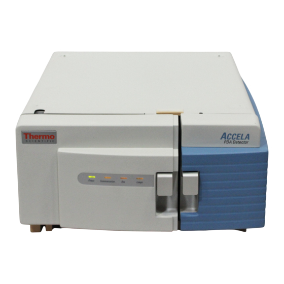
Introduction The Accela PDA Detector is a member of the Accela family of ultra high-performance LC instruments (see Figure Contents • Functional Description • LightPipe Flowcell • Lamp Lifetime and Detector Noise • Status LEDs • Specifications Figure 1. Accela PDA Detector... -
Page 22: Functional Description
Figure 2. The PDA detector optical system Deuterium Beam combiner LightPipe flowcell lamp Focusing lens Beam shaper Filter wheel Folding mirror × photo diode array Fixed grating Attenuators Tungsten-halogen lamp Accela PDA Detector Hardware Manual Thermo Scientific... -
Page 23: Lightpipe Flowcell
LightPipe Flowcell The Accela PDA Detector ships with a 10 mm or 50 mm LightPipe flowcell. The internal bore of the 10 mm LightPipe flowcell is 10 mm long and has a volume of 2 μL. - Page 24 Figure 4. End of the LightPipe flowcell Optical fibers Inlet port Figure 5. LightPipe flowcell with protective end caps Protective end caps for storage 10 mm LightPipe flowcell 50 mm LightPipe flowcell Accela PDA Detector Hardware Manual Thermo Scientific...
-
Page 25: Lamp Lifetime And Detector Noise
Lamp Lifetime and Detector Noise Lamp Lifetime and Detector Noise The Accela PDA Detector has two lamps. The tungsten-halogen lamp emits light in the visible region, and the deuterium lamp emits light in the ultraviolet region. With use, the deuterium lamp emits less and less light before it fails to ignite (see Figure 6). -
Page 26: Selecting An Appropriate Diode Array Scan Rate
0.5 seconds. • For fast chromatography applications that have chromatographic peaks with baseline widths of less than 0.5 seconds, select the 80 Hz diode array scan rate. Accela PDA Detector Hardware Manual Thermo Scientific... -
Page 27: Status Leds
Four status LEDs labeled Power, Communication, Run, and Lamps are located on the left door of the detector (see Figure Table 1 lists the status LEDs and their meaning. Figure 7. Accela PDA Detector status LEDs Power Communication Lamps Table 1. Status LEDs and meanings State... -
Page 28: Specifications
Introduction Specifications Specifications The specifications for the Accela PDA Detector are as follows: Wavelength range: 190 nm to 800 nm continuous ±1 nm at 254 nm and 656 nm Wavelength accuracy: Digital wavelength resolution: 1.2 nm Absorbance range: 2.0 AU to +4.0 AU, 20-bit resolution ≤... -
Page 29: Installation
Making Initial Instrument Preparations • Making the Back Panel Connections • Installing the LightPipe Flowcell • Connecting the Remote Outputs • Turning On the Detector for the First Time • Completing the Installation and Verifying Operation Thermo Scientific Accela PDA Detector Hardware Manual... -
Page 30: Installation Checklist
Power on the detector for the first time. page Install software and connect remote page communication outputs, as required. Configure the Accela PDA Detector for Chapter 3, “Configuration.” control from your chromatography data system. Adjust the light throughput to the diode For the Xcalibur data system, see array. -
Page 31: Unpacking And Inspecting The Instrument
If you find any damage, save the shipping materials and immediately contact the shipping company. Check the shipping container for the Accela PDA Detector, a LightPipe Flowcell Kit, a power cable, and an accessory kit that contains the following items: •... -
Page 32: Making The Back Panel Connections
2. Plug one of the connectors labeled PUMP into the 8-pin receptacle on the back panel of the Accela Pump. 3. Plug the autosampler connector (identified by the A/S tag on its adjacent cable) into the left, 8-pin receptacle on the back panel of the Accela Autosampler. Accela PDA Detector Hardware Manual Thermo Scientific... - Page 33 For information on connecting an MS detector, refer to the Accela Getting Connected Guide. Figure 8. Seven-connector version of the system interconnect cable Autosampler connector Figure 9. Back panel of Accela PDA Detector Interconnect cable Ethernet 8-pin connector receptacle Analog signals...
-
Page 34: Connecting The Analog Outputs
IMPORTANT Do not connect the detector ground terminals to any earth ground on your data system computer. Doing so leads to an increased noise level and a subsequent decrease in sensitivity. Figure 10. Analog signal connectors Analog signal 8-pin connectors Accela PDA Detector Hardware Manual Thermo Scientific... -
Page 35: Setting The Analog Output Voltage
(Figure 10). Setting the Unit ID The Accela PDA Detector ships with the unit ID preset using the two rotary switches located on the back panel. Figure 11 shows the rotary switches preset to a value of 01. The range of values for the unit ID is 01 to 99. - Page 36 Use the ZERO connection on the back panel of the detector to zero the detector signal output from a remote device (generally at the start or end of each sample run). You can remotely zero the Accela PDA Detector with either a TTL low signal or with a contact closure.
-
Page 37: Installing The Lightpipe Flowcell
Figure 13). Figure 13. Lightpipe flowcell access cover Captive screw LightPipe flowcell Slot for access cover outlet tubing STANDARD FILTER WHEEL 1 : OPEN 2 : HOLMIUM OXIDE FILTER Slot for inlet tubing Thermo Scientific Accela PDA Detector Hardware Manual... - Page 38 0.005 in. ID, PEEK tubing (included in the MS detector accessory kit) to the outlet port of the LightPipe flowcell and to connect the other end of the tubing to the inlet port of the MS detector. Accela PDA Detector Hardware Manual Thermo Scientific...
- Page 39 Installing the LightPipe Flowcell IMPORTANT If you have several detectors (fluorescence, refractive index, electrochemical, and so on) hooked up in a series, place your Accela PDA Detector closest to the column outlet. The LightPipe flowcell in the Accela PDA Detector can withstand the greatest backpressure.
- Page 40 10. Replace the flowcell access cover, ensuring that the inlet and outlet tubing pass through the slots (see Figure 13 page 17) without being pinched. Tighten the captive screw to secure the flowcell access cover to the detector. 11. Close the front doors of the detector. Accela PDA Detector Hardware Manual Thermo Scientific...
-
Page 41: Connecting The Remote Outputs
Setting the Remote Output Polarities from the Xcalibur Data System To set the polarity of the remote outputs 1. Install the Xcalibur data system if you have not already done so. 2. Add the Accela PDA Detector to the configuration for your instrument. See Chapter 3, “Configuration.”... - Page 42 Installation Connecting the Remote Outputs Figure 17. Configuration page of the Accela PDA Direct Control dialog box (Xcalibur data system) 8. In the Analog Outputs area of the Configuration page, check the current settings of the outputs. 9. Change the settings to match the connecting equipment if necessary.
-
Page 43: Changing The Remote Output Polarities From The Chromquest Data
The Accela PDA page of the Instrument Status window appears (see Figure 18). Figure 18. Accela PDA page of the Instrument Status window (ChromQuest data system) 6. In the Output States area, click the appropriate button. Thermo Scientific Accela PDA Detector Hardware Manual... -
Page 44: Turning On The Detector For The First Time
6. Turn the power on by pushing the power button in to engage it. The Power LED turns amber as it downloads the operational file, and then turns solid green. If it does not light at all, see Chapter 7, “Troubleshooting.” Accela PDA Detector Hardware Manual Thermo Scientific... -
Page 45: Completing The Installation And Verifying Operation
Completing the Installation and Verifying Operation Completing the Installation and Verifying Operation The Accela PDA Detector is calibrated at the factory. During installation, a Thermo Fisher Scientific field service engineer adjusts the light throughput and recalibrates the detector. The PDA detector uses the holmium oxide spectrum to verify its wavelength accuracy. - Page 46 • For the ChromQuest data system, see Chapter 5, “ChromQuest Diagnostics for the PDA Detector.” • For the Xcalibur data system, see Chapter 4, “Xcalibur Diagnostics for the PDA Detector.” Accela PDA Detector Hardware Manual Thermo Scientific...
-
Page 47: Chapter 3 Configuration
The diode array scan rate is the unfiltered rate at which the PDA detector samples the light intensities for the diode array. You can set the Accela PDA Detector (80 Hz version) to scan the array at a 20, 40, or 80 Hz sampling rate. -
Page 48: Thermo Foundation Instrument Configuration
Figure 22. Thermo Foundation Instrument Configuration window 2. In the Available Devices list, double-click each of your Accela devices. As you double-click a device in the Available Devices list, it appears in the list of configured devices. Accela PDA Detector Hardware Manual Thermo Scientific... - Page 49 Configuration Thermo Foundation Instrument Configuration 3. Complete the configuration of the Accela PDA Detector as follows: a. Double-click the Accela PDA button. The Accela PDA Configuration dialog box appears (see Figure 23). Figure 23. Accela PDA Configuration dialog box (Thermo Foundation) b.
-
Page 50: Chromquest Data System Instrument Configuration
A shortcut menu appears. 4. Choose Configure > Instrument. The Instrument Configuration dialog box appears (see Figure 24). Figure 24. Instrument Configuration dialog box 5. Type a name for your instrument in the Instrument name box. Accela PDA Detector Hardware Manual Thermo Scientific... - Page 51 6. Depending on the current configuration of the instrument, do one of the following: • If you are adding the Accela PDA Detector to a current configuration for your Accela LC stack, leave the selection in the Instrument type list as Accela.
- Page 52 69). 10. Click OK to accept the settings and close the Accela PDA Configuration dialog box. 11. Click OK to close the Detector Configuration dialog box. 12. If you have not already done so, configure the remaining modules of your Accela LC stack.
-
Page 53: Chapter 4 Xcalibur Diagnostics For The Pda Detector
IMPORTANT Before calibrating the PDA detector, make sure that the diode array is not saturated. Contents • Opening the Accela PDA Direct Control Dialog Box • Controlling the Lamps from the Xcalibur Data System • Monitoring Lamp Performance from the Xcalibur Data System •... -
Page 54: Opening The Accela Pda Direct Control Dialog Box
Opening the Accela PDA Direct Control Dialog Box Opening the Accela PDA Direct Control Dialog Box Use the Accela PDA Direct Control dialog box to control the lamps, perform diagnostics, and calibrate the PDA detector. To open the Accela PDA Direct Control dialog box 1. -
Page 55: Controlling The Lamps From The Xcalibur Data System
“Opening the Accela PDA Direct Control Dialog Box” page 34). 2. Click the Configuration tab. The Configuration page appears (see Figure 28). Figure 28. Configuration page of the Accela PDA Direct Control dialog box Thermo Scientific Accela PDA Detector Hardware Manual... -
Page 56: Resetting The Lamp Lifetime
Resetting the Lamp Lifetime To reset the displayed lamp lifetime 1. Open the Accela PDA Direct Control dialog box (see “Opening the Accela PDA Direct Control Dialog Box”... - Page 57 5. Click OK to apply the new lamp startup time. Use the Programmed Start option to pre-warm the lamps before starting a sequence of sample analyses. Thermo Scientific Accela PDA Detector Hardware Manual...
-
Page 58: Monitoring Lamp Performance From The Xcalibur Data System
In the Xcalibur Roadmap view, click the Instrument Setup button. The Instrument Setup view appears. b. In the view bar, click the Accela PDA button. The Accela PDA Instrument Setup view appears with the Accela PDA Method page displayed. Accela PDA Detector Hardware Manual... - Page 59 To set the X-axis of the spectrum on the Display page to diode numbers, in the Units area, select the Diode/Intensity option (see Figure 30). Figure 30. Accela PDA Method page with the selection of the Diodes/Intensity option Diode/Intensity option b. To make the scan parameters available, select the Collect Spectral Data check box.
-
Page 60: Viewing An Intensity Scan
Viewing an Intensity Scan To view an intensity scan 1. From the menu bar of the Accela PDA view in the Instrument Setup window, choose Accela PDA > Direct Control. The Accela PDA Direct Control dialog box appears. 2. Click the Display tab. - Page 61 Microsoft Word. Keep this scan for future comparisons to see if there is degradation in light intensity. Date the printout and add it to your maintenance records. Figure 32. Display page Start Data –or– Snapshot button Thermo Scientific Accela PDA Detector Hardware Manual...
-
Page 62: Adjusting The Light Throughput With The Xcalibur Data System
2. If you have not already done so, create a display method that scans from diode 2 to diode 511 with a diode step of 1 and that displays the default discrete channel wavelengths (see “Creating a Display Method to View Light Intensity” page 38). Accela PDA Detector Hardware Manual Thermo Scientific... - Page 63 5. Adjust the right attenuator tab (Visible attenuation) to achieve a Channel C value as close as possible to 900000 intensity counts without saturating the array. 6. After you finish adjusting the attenuators, close the front doors of the detector. Thermo Scientific Accela PDA Detector Hardware Manual...
-
Page 64: Calibrating The Pda Detector From The Xcalibur Data System
2. Turn on both lamps and wait one hour for the lamps to equilibrate (see “Controlling the Lamps from the Xcalibur Data System” page 35). Leave the Accela PDA Direct Control dialog box open. 3. Click the Calibration tab. The Calibration page appears (see Figure 33). - Page 65 5. Read the preconditions and verify that they have been met: • If the preconditions have been met, click Next to proceed with the calibration. • If the preconditions have not been met, click Cancel. Then prepare the Accela PDA Detector for calibration and begin this procedure again.
- Page 66 Page 3 of the Dark Current Calibration wizard appears (see Figure 36). You can export the results of the calibration from this page. Figure 36. Page 3 of the Dark Current Calibration wizard Accela PDA Detector Hardware Manual Thermo Scientific...
- Page 67 After you save the file with a name of your choice, you can view or print the contents of the file using any text editing program (see Figure 37). Figure 37. Accela PDA dark current calibration text file 9. On page 3 (see Figure 36 page 46) of the Dark Current Calibration wizard, click Apply to apply the calibration results to the detector.
- Page 68 The detector stores the calibration results. The date and time of the calibration appears in the Dark Current Calibration area of the Calibration page following Last Calibration (see Figure 39). Figure 39. Calibration page with dark current calibration results Accela PDA Detector Hardware Manual Thermo Scientific...
-
Page 69: Performing A Wavelength Calibration From The Xcalibur Data System
3. After the detector has reached a stable temperature (approximately one hour after you turn on the lamps), proceed with the calibration: a. In the Accela PDA Direct Control dialog box, click the Calibration tab The Calibration page appears (see Figure 40). - Page 70 UV and Visible wavelength regions. The holmium oxide absorbance maxima are selected from a spectrum published in “Holmium Oxide Solution Wavelength Standard from 240 to 640 nm - SRM 2034 (NIST Special Publication 260-54).” Accela PDA Detector Hardware Manual Thermo Scientific...
- Page 71 Calibrating the PDA Detector from the Xcalibur Data System Figure 42. Page 2 of the Wavelength Calibration wizard with a list of calibration files b. Click Next. Page 3 of the Wavelength Calibration wizard appears (see Figure 43). Thermo Scientific Accela PDA Detector Hardware Manual...
- Page 72 When you see the message: Click the Next button to proceed with calibration, click Next. Page 4 of the Wavelength Calibration wizard appears (see Figure 44). Figure 44. Page 4 of the Wavelength Calibration wizard Accela PDA Detector Hardware Manual Thermo Scientific...
- Page 73 When you see the message: Click the Next button to proceed with calibration, click Next. Page 6 of the Wavelength Calibration wizard appears (see Figure 46). Thermo Scientific Accela PDA Detector Hardware Manual...
- Page 74 The Next button becomes active (see Figure 47). Figure 47. Page 7 of the Wavelength Calibration wizard with an active Next button 10. Click Next. Page 8 of the Wavelength Calibration wizard appears (see Figure 48). Accela PDA Detector Hardware Manual Thermo Scientific...
- Page 75 ±1 nm, call your Thermo Fisher Scientific service representative for assistance. 12. (Optional) Print a report of the calibration results: a. Click Export Results to print the results to a file. The Save As dialog box appears (see Figure 49). Thermo Scientific Accela PDA Detector Hardware Manual...
- Page 76 In the File name box, type a name, and then click Save. You can view or print the calibration results using any text editing program (see Figure 50). Figure 50. Wavelength calibration report opened in Notepad Accela PDA Detector Hardware Manual Thermo Scientific...
-
Page 77: Retrieving, Viewing, Printing, And Clearing The Event Log
For a list of error messages that can appear in the event log along with suggested solutions, see “Log Entries” page 100. To open, print, save, or clear the event log in the Xcalibur data system 1. Open the Accela PDA Direct Control dialog box (see “Opening the Accela PDA Direct Control Dialog Box” page 34). - Page 78 Retrieving, Viewing, Printing, and Clearing the Event Log Note When you first open the Information page, the event area might be blank. Figure 52. Information page of the Accela PDA Direct Control dialog box with the event log 3. Do one of the following: a.
-
Page 79: Checking The Firmware Version
Xcalibur Diagnostics for the PDA Detector Checking the Firmware Version Checking the Firmware Version Occasionally, upgraded firmware becomes available for the Accela PDA Detector. Ask your Thermo Fisher Scientific Service Representative about the availability of new firmware. To check the firmware version 1. -
Page 81: Chapter 5 Chromquest Diagnostics For The Pda Detector
With use, the deuterium lamp produces less and less light so the system performance changes as the lamp’s remaining lifetime hours decrease. For information on configuring your Accela PDA Detector, see “ChromQuest Data System Instrument Configuration”... -
Page 82: Accessing The Direct Controls For The Accela Pda Detector
Accessing the Direct Controls for the Accela PDA Detector Accessing the Direct Controls for the Accela PDA Detector You access the direct controls and the Diagnostics dialog box for the Accela PDA detector from the Accela PDA page (see Figure 54) of the Instrument Status window. -
Page 83: Controlling The Lamps From The Chromquest Data System
From the ChromQuest data system, you can turn the lamps on or off and view the lamp’s usage hours from the Accela PDA page of the Instrument Status window or from the Lamps page of the Accela PDA Diagnostics dialog box. - Page 84 • Click Reset to reset the stored total run time for the associated lamp to zero and update the Last Reset readback to the current date and time. After you replace a lamp, reset its lamp usage hours to zero. Accela PDA Detector Hardware Manual Thermo Scientific...
-
Page 85: Monitoring Lamp Performance From The Chromquest Data System
“Controlling the Lamps from the ChromQuest Data System” page 63). Wait for one hour for both lamps to equilibrate. 4. Open the Accela PDA Diagnostics dialog box (see “Accessing the Direct Controls for the Accela PDA Detector” page 62). 5. Click the Control tab. - Page 86 9. Click Load To Detector. A dialog box containing the message, Method Has Been Downloaded, appears. 10. Click OK. 11. Click the Display tab. The Display page appears (see Figure 57). Accela PDA Detector Hardware Manual Thermo Scientific...
- Page 87 13. In the Data area, click Start to refresh the display. 14. Save a printout or an electronic copy of the spectrum. Date the printout and add it to your maintenance records (see “Recording the Performance of the Lamps” page 68). Thermo Scientific Accela PDA Detector Hardware Manual...
-
Page 88: Recording The Performance Of The Lamps
1. On the Display page, stop the data stream by clicking Stop in the Data area. 2. Click Snapshot. 3. Using Microsoft Windows™ Explorer, browse to the ChromQuest directory. 4. Click the WaveData.csv file. Microsoft Excel opens. Accela PDA Detector Hardware Manual Thermo Scientific... -
Page 89: Adjusting The Light Throughput With The Chromquest Data System
Decreasing light throughput increases baseline noise. Increasing light throughput can saturate the diode array. When the array is saturated, the response from the Accela PDA Detector is a flat baseline. Adjust the attenuators as the light output from the deuterium lamp decreases and whenever you do the following: •... -
Page 90: Setting Up The Spectral And Discrete Channel Displays
Adjusting the Light Throughput with the ChromQuest Data System Setting Up the Spectral and Discrete Channel Displays To set up the spectral and discrete channel displays 1. Open the Diagnostics dialog box for the Accela PDA Detector (see “Accessing the Direct Controls for the Accela PDA Detector”... -
Page 91: Adjusting The Attenuators
Figure 60 on the next page show saturation of the diode array. Figure 58. Display page (after you click On in the Status area and Start in the Data area) Discrete channel readbacks Thermo Scientific Accela PDA Detector Hardware Manual... - Page 92 Figure 60. Saturated diode array (UV region and visible region) The diode array is saturated in the UV region and the visible region. 4. After you finish adjusting the attenuators, close the front doors of the detector. Accela PDA Detector Hardware Manual Thermo Scientific...
-
Page 93: Calibrating The Pda Detector From The Chromquest Data System
Performing a Wavelength Calibration from the ChromQuest Data System Preparing the PDA Detector for Calibration To prepare the Accela PDA Detector for calibration 1. Replace the LC column with a flow restrictor. 2. Set up the system to pump HPLC-grade water or HPLC-grade methanol through the flowcell, and then start the solvent flow. - Page 94 1. Prepare the PDA detector for calibration (see “Preparing the PDA Detector for Calibration” page 73). 2. Open the Diagnostics dialog box for the Accela PDA Detector (see “Accessing the Direct Controls for the Accela PDA Detector” page 62). 3. Click the Calibration tab.
-
Page 95: System
To perform a wavelength calibration with ChromQuest 1. Open the Accela PDA Diagnostics dialog box (see “Accessing the Direct Controls for the Accela PDA Detector”... - Page 96 “Holmium Oxide Solution Wavelength Standard from 240 to 640 nm - SRM 2034 (NIST Special Publication 260-54).” The holmium oxide bands of the selected file appear in the Wavelength File area (see Figure 64). Accela PDA Detector Hardware Manual Thermo Scientific...
- Page 97 5. If all of the preconditions are met, click OK. The data system collects a background spectrum, which it uses to remove the absorbance contribution of the mobile phase. When the background collection is complete, another message box appears (see Figure 66). Thermo Scientific Accela PDA Detector Hardware Manual...
- Page 98 If the delta values are not within the range of ±1 nm, repeat the wavelength calibration procedure for verification. b. If, after applying a new calibration, the delta values are still not within the range of ±1 nm, call your Thermo Fisher Scientific service representative for assistance. Accela PDA Detector Hardware Manual Thermo Scientific...
- Page 99 The date and time of the wavelength calibration appear in the Wavelength area. This information is also stored by the PDA detector. Note You can click Cancel in any of the Calibration dialog boxes at any time to cancel the calibration process. Thermo Scientific Accela PDA Detector Hardware Manual...
-
Page 100: Displaying, Printing, And Clearing The Error Log
• Click Get to retrieve and display the error log information from the detector. Figure 69 shows a sample Error Log. • Click Print to print a copy of the displayed log. • Click Clear Log to clear the log. Accela PDA Detector Hardware Manual Thermo Scientific... -
Page 101: Checking The Firmware Version
62). 2. Click the Display tab. The Display page appears. 3. Click On. The firmware version of the Accela PDA Detector appears in the Status area on the left side of the Display page (see Figure 57 page 67). -
Page 103: Routine Maintenance
Routine Maintenance This chapter describes how to clean the LightPipe flowcell and how to replace the lamps. Proper maintenance ensures the optimum performance of the Accela PDA Detector. You are responsible for maintaining your PDA detector by properly performing the maintenance procedures on a regular basis. -
Page 104: Recommended Maintenance
Routine Maintenance Recommended Maintenance Recommended Maintenance Table 3 lists recommendations for routine maintenance of the Accela PDA Detector. Use the table as a basis for developing your maintenance program in accordance with your company practices. Table 3. Recommended routine maintenance... -
Page 105: Cleaning The External Surfaces Of The Detector
Cleaning the LightPipe Flowcell with Nitric Acid Removing the LightPipe Flowcell To clean the LightPipe flowcell, remove it from the Accela PDA Detector. To remove the LightPipe flowcell 1. Turn the detector power off and disconnect the power cord from the back panel of the detector. - Page 106 Routine Maintenance Cleaning the LightPipe Flowcell Figure 70. Accela PDA Detector with the front doors open Captive screw Flowcell access cover Figure 71. Retaining block and retaining block knob Retaining bolt Retaining block Retaining block knob Accela PDA Detector Hardware Manual...
-
Page 107: Cleaning The Lightpipe Flowcell With Organic Solvents
25 to 40 mL of HPLC-grade water (or its equivalent) through the system to remove any salts before you flush the pump with the cleaning solvents. This wash helps to avoid precipitation problems. Thermo Scientific Accela PDA Detector Hardware Manual... -
Page 108: Cleaning The Lightpipe Flowcell With Nitric Acid
CAUTION Thermo Fisher Scientific does not recommend using a syringe to force acid solutions through the flowcell. Pressurizing the syringe could cause a leak or rupture, resulting in a dangerous and uncontrolled spraying of acid. Accela PDA Detector Hardware Manual Thermo Scientific... -
Page 109: Replacing The Lamps
CAUTION The lamp cover becomes very hot when the lamps are on. After you turn off the lamps and the PDA detector, wait 30 minutes for the lamp cover to cool before removing it. Thermo Scientific Accela PDA Detector Hardware Manual... - Page 110 Note You do not have to detach the grounding cables to access the LED cable behind the metal plate. Figure 72. Screw that secures the metal plate to the left door Screw Grounding cables Accela PDA Detector Hardware Manual Thermo Scientific...
- Page 111 CAUTION After you turn off the lamps and the PDA detector, wait 30 minutes for the lamp cover to cool before removing it. The lamp cover becomes very hot when the lamps are on. Thermo Scientific Accela PDA Detector Hardware Manual...
- Page 112 For this reason, wear clean, talc-free gloves when you handle the lamps. If either lamp requires cleaning, use a lint-free lens paper moistened with methanol or isopropanol before replacing the lamp cover. Accela PDA Detector Hardware Manual Thermo Scientific...
- Page 113 Loosen but do not remove the two Phillips head screws by turning them approximately four turns. c. Lift and gently twist the mounting flange counterclockwise to free the lamp (see Figure 77). Figure 76. Lamp connections Deuterium lamp connector Tungsten lamp connector Thermo Scientific Accela PDA Detector Hardware Manual...
- Page 114 (see Figure 77). To install a lamp, perform the preceding removal procedure in reverse order. IMPORTANT Remember to reset the elapsed lamp hours after replacing a lamp (see “Resetting the Lamp Lifetime” page Accela PDA Detector Hardware Manual Thermo Scientific...
-
Page 115: Replacing The Fuses
2. Insert the tip of a narrow-blade screwdriver into one of the two openings on the exterior surface of the power entry module, and then apply leverage to gain access to the power entry module’s door (see Figure 78). Figure 78. Loosening the power entry module’s door Thermo Scientific Accela PDA Detector Hardware Manual... - Page 116 Figure 81. View of the fuse holder Fuse holder 5. Replace the fuses. 6. Put the fuse holder back into the power entry module, and then close the power entry module door until it snaps in. Accela PDA Detector Hardware Manual Thermo Scientific...
-
Page 117: Chapter 7 Troubleshooting
Remove systems that can cause voltage on power line. fluctuations, for example, ovens; isolate the detector to a “quiet” circuit; or use an uninterruptible power supply (UPS) that is safety certified (UL, TUV, SEMKO, DEMKO, and so on). Thermo Scientific Accela PDA Detector Hardware Manual... - Page 118 Increase the flow rate until you remove the flowcell. bubble. Connect a backpressure device to the flowcell outlet (check the backpressure rating to avoid rupturing the flowcell). Excessive temperature fluctuations. Remove the system from drafts. Thermostatically control the column temperature. Accela PDA Detector Hardware Manual Thermo Scientific...
- Page 119 Ethernet connection may be loose. Check the Ethernet connection to the data system computer. Comm LED is amber Connection to the data system Check the Ethernet connection to the data computer has been lost. system computer. Thermo Scientific Accela PDA Detector Hardware Manual...
-
Page 120: Log Entries
Turn on the lamps and allow 1½ hours for warm-up. Log Entries This section describes the various log entries that are possible when operating the Accela PDA Detector from your Thermo Scientific data system. Note For further information, document the log entry and contact Thermo Fisher Scientific technical support. -
Page 121: Warning Messages
• Deuterium lamp was turned off • Tungsten lamp was turned on • Tungsten lamp was turned off • Wavelength calibration reset • Lamp calibration reset • Wavelength calibration applied • Lamp calibration applied Thermo Scientific Accela PDA Detector Hardware Manual... -
Page 123: Chapter 8 Accessories And Replaceable Parts
NIST traceable) 802259 Backpressure regulator Table 8. Cables and connectors for back panel connections Part number Description 70111-63302 Ethernet cable 60053-63034 Interconnect cable (seven-connector cable) Thermo Scientific Accela PDA Detector Hardware Manual... - Page 124 60257-63003 Power switch 60057-61000 LED assembly 60257-60007 Standard filter wheel 803226 Cable, ribbon, CPU to Lamp Power Supply PCB Table 11. Accela PDA Detector Accessory kit Part number Description A3538-010 Cable adapter, RJ45/14-D89FM A3638-110 Cable, 4-pin, RJ45 6040-0103 Analog cable, detector 00004-02511 Connector, plug, 8-pin, 3.81 mm pitch, minicombicon...
-
Page 125: Index
ChromQuest ChromQuest specifying in Xcalibur print utility diode spacing Snapshot button wavelength calibration of detector diode voltage leakage cleaning procedures disposal requirements external surfaces drift LightPipe flowcell compliance, WEEE Thermo Scientific Accela PDA Detector Hardware Manual... - Page 126 ChromQuest remote communications inputs in Xcalibur usage hours, resetting remote controls in ChromQuest rise time in Xcalibur Accela PDA Detector Hardware Manual Thermo Scientific...
- Page 127 See also lamps lifetime unit ID UPS (uninterruptible power supply) warm-up time warning messages wavelength accuracy, calibrating in ChromQuest in Xcalibur wavelength accuracy, specification wavelength range WEEE compliance Thermo Scientific Accela PDA Detector Hardware Manual...
Need help?
Do you have a question about the Accela PDA and is the answer not in the manual?
Questions and answers