
Related Manuals for Thermo Scientific Surveyor PDA Plus


Summary of Contents for Thermo Scientific Surveyor PDA Plus
- Page 1 Thermo Surveyor PDA Plus Detector Hardware Manual 60053-97107 Revision F December 2013...
- Page 2 © 2013 Thermo Fisher Scientific Inc. All rights reserved. Foundation and Xcalibur are registered trademarks and ChromQuest, Surveyor Plus, and LightPipe are trademarks of Thermo Fisher Scientific Inc in the United States. Teflon is a registered trademark of E. I. du Pont de Nemours and Company in the United States and other countries.
- Page 3 Thermo Fisher Scientific. To ensure continued compliance with EMC and safety standards, replacement parts and additional components, options, and peripherals must be ordered from Thermo Fisher Scientific or one of its authorized representatives. Surveyor PDA Plus Detector EMC Directive 89/336/EEC EMC compliance has been evaluated by Underwriters Laboratories Inc.
- Page 4 Notice on Lifting and Handling of Thermo Scientific Instruments For your safety, and in compliance with international regulations, the physical handling of this Thermo Fisher Scientific instrument requires a team effort to lift and/or move the instrument.
- Page 5 WEEE Compliance This product is required to comply with the European Union’s Waste Electrical & Electronic Equipment (WEEE) Directive 2002/96/EC. It is marked with the following symbol: Thermo Fisher Scientific has contracted with one or more recycling or disposal companies in each European Union (EU) Member State, and these companies should dispose of or recycle this product.
- Page 6 Conformité DEEE Ce produit doit être conforme à la directive européenne (2002/96/EC) des Déchets d'Equipements Electriques et Electroniques (DEEE). Il est marqué par le symbole suivant: Thermo Fisher Scientific s'est associé avec une ou plusieurs compagnies de recyclage dans chaque état membre de l’union européenne et ce produit devrait être collecté...
- Page 7 San Jose products. im Unklaren sind, setzen Sie sich, bevor Sie póngase en contacto con el personal de servicio técnico l’assistance technique pour les produits Thermo Scientific fortfahren, mit dem technischen Support für de los productos Thermo Scientific San Jose.
- Page 8 Technical Support for Thermo Scientific im unklaren sind, setzen Sie sich, bevor Sie póngase en contacto con el personal de servicio técnico l’assistance technique pour les produits Thermo Scientific San Jose products. fortfahren, mit Ihrer lokalen technischen de los productos Thermo Scientific San Jose.
- Page 9 す。この標識記号は機器にも表示されています。この危険の詳細につい is not included in the other categories. 危险的详细信息,参阅适当的仪器手册。若对任何步骤的安全事项有疑 ては、機器のマニュアルを参照してください。 This symbol also appears on the 问,联系 Thermo Scientific San Jose 产品的技术支持中心。 手順の安全性にご不明な点がある場合は、Thermo Scientific San Jose 製品の instrument. For details about the hazard, テクニカルサポートまでお問い合わせください。 refer to the instrument manual. When the safety of a procedure is questionable, contact Technical Support for Thermo Scientific San Jose products.
- Page 10 作業の障害物 : 床にあるコード、ホース、その他の物体に注意してく 绊倒危险:注意地面上的线、管或其他物品。 or other objects located on the floor. ださい。 When the safety of a procedure is 手順の安全性にご不明な点がある場合は、Thermo Scientific San Jose 製品の 如对安全程序有疑问,联系 Thermo Scientific San Jose 产品的技术支持 questionable, contact Technical Support テクニカルサポートまでお問い合わせください。 中心。 for Thermo Scientific San Jose products.
-
Page 11: Table Of Contents
Configuration ............23 Configuring the Surveyor PDA Plus Detector in Xcalibur....24 Configuring the Surveyor PDA Plus Detector in ChromQuest . - Page 12 Replacing the Lamps ..........91 Surveyor PDA Plus Detector Hardware Manual...
- Page 13 Index ............. . .113 Thermo Scientific Surveyor PDA Plus Detector Hardware Manual xiii...
-
Page 15: Preface
Preface This Surveyor PDA Plus Detector Hardware Manual provides you with information on how to set up and maintain the Surveyor PDA Plus Detector. Contents • Related Documentation • Cautions and Special Notices • Contacting Us Related Documentation In addition to this guide, Thermo Fisher Scientific provides the following documents for the Surveyor MS Pump and the Surveyor MS Pump Plus: •... -
Page 16: Cautions And Special Notices
The PDA detector contains a LightPipe flow cell that you can easily damage if you handle it by its ends. Do not to touch the fiber optics that are exposed at the ends of the flow cell. See the following figure. Fiber optic Surveyor PDA Plus Detector Hardware Manual Thermo Scientific... -
Page 17: Good Laboratory Practices
(for example,% RSDs on retention times and peak areas, peak shape and resolution). At a minimum, keep a chromatogram of a typical sample and standard mixture, well documented with system Thermo Scientific Surveyor PDA Plus Detector Hardware Manual xvii... - Page 18 LC system. However, if a leak occurs, it should be corrected as soon as possible. Always wear eye and skin protection when operating or maintaining an LC system. Always shut down the system and return it to atmospheric pressure before attempting any maintenance. xviii Surveyor PDA Plus Detector Hardware Manual Thermo Scientific...
-
Page 19: Contacting Us
To suggest changes to the documentation or to the Help • Fill out a reader survey online at www.surveymonkey.com/s/PQM6P62. • Send an e-mail message to the Technical Publications Editor at techpubs-lcms@thermofisher.com. Thermo Scientific Surveyor PDA Plus Detector Hardware Manual... -
Page 21: Introduction
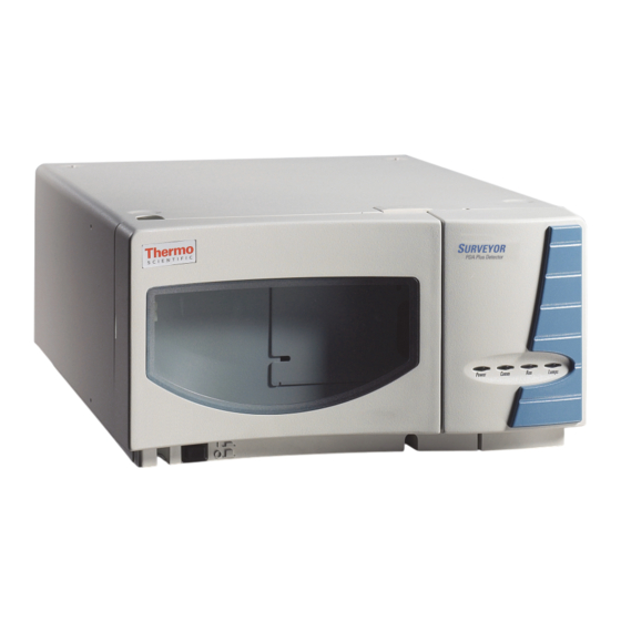
Introduction The Surveyor PDA Plus Detector is a member of the Surveyor Plus™ family of LC instruments (see Figure Contents • Functional Description • LightPipe Flow Cell • Status LEDs • Specifications Figure 1. Surveyor PDA Plus Detector Thermo Scientific... -
Page 22: Functional Description
The beam shaper is a fiber bundle. Its entrance aperture is circular to collect light from the flow cell. The Surveyor PDA Plus Detector Hardware Manual Thermo Scientific... -
Page 23: Lightpipe Flow Cell
LightPipe Flow Cell The Surveyor PDA Plus Detector ships with a 10-mm LightPipe flow cell. Thermo Fisher Scientific also offers an optional 50 mm LightPipe flow cell. The internal bore of the 50-mm LightPipe flow cell is 50 mm long and has a volume of 10 L. - Page 24 End of LightPipe flow cell with a view of the sensitive optical fiber and the inlet port Optical fiber Inlet port Figure 6. LightPipe flow cell with protective end caps Protective end caps for storage 10-mm LightPipe flow cell 50-mm LightPipe flow cell Surveyor PDA Plus Detector Hardware Manual Thermo Scientific...
-
Page 25: Status Leds
Four status LEDs (light-emitting diodes)—labeled Power, Communication, Run, and Lamps—are located on the left door of the detector (see Figure Table 1 lists states of the status LEDs. Figure 7. Surveyor PDA Plus Detector status LEDs Power Communication Lamps Table 1. Status LED states State Amber... -
Page 26: Specifications
Introduction Specifications Specifications The specifications for the Surveyor PDA Plus Detector are as follows: Wavelength Range: 190 nm to 800 nm continuous 1 nm at 254 nm and 656 nm Wavelength Accuracy: Digital Wavelength Resolution: 1.2 nm Absorbance Range: 2.0 AU to +4.0 AU, 20-bit resolution ... -
Page 27: Installation
Checking the Power Setting and Fuses • Making the Back Panel Connections • Installing the LightPipe Flow Cell • Turning On the Detector for the First Time • Connecting Remote Outputs • Completing the Installation Thermo Scientific Surveyor PDA Plus Detector Hardware Manual... -
Page 28: Installation Checklist
19). Download the PDA detector firmware, if required. See Appendix A, “Firmware.” Configure the Surveyor PDA Plus Detector for control from your chromatography data system. See Chapter 3, “Configuration.” Calibrate the Surveyor PDA Plus Detector (see “Calibrating the PDA Detector”... -
Page 29: Unpacking And Inspecting The Instrument
If you find any damage, save the shipping materials and immediately contact the shipping company. The shipping container should contain the Surveyor PDA Plus Detector, a LightPipe flow cell kit, a power cable, and an accessory kit containing the following items: •... -
Page 30: Checking The Power Setting And Fuses
4. If necessary, slide out the voltage selection PC board and reinstall it so that the desired voltage label is upright and readable. This voltage must agree with the incoming line voltage. 5. Slide the fuse holder back into the power entry module until it snaps in. Surveyor PDA Plus Detector Hardware Manual Thermo Scientific... -
Page 31: Making The Back Panel Connections
DETECTOR, two pump connectors labeled PUMP, an autosampler connector, and an MS detector connector. Figure 9. Seven-connector version of the system interconnect cable Autosampler connector Thermo Scientific Surveyor PDA Plus Detector Hardware Manual... - Page 32 IMPORTANT Connecting the Surveyor MS Pump Plus requires an additional adapter cable. Refer to the Surveyor Plus Getting Connected Guide for information on connecting an MS detector. Figure 10. Back panel of Surveyor PDA Plus Detector Interconnect cable 8-pin connector Analog signals...
-
Page 33: Connecting The Analog Outputs
IMPORTANT Do not connect the detector ground terminals to any earth ground on your data system computer. Doing so leads to an increased noise level and a subsequent decrease in sensitivity. Figure 11. View of the analog outputs 8-pin analog connector Thermo Scientific Surveyor PDA Plus Detector Hardware Manual... -
Page 34: Setting The Analog Output Voltage
Use the ZERO connection on the back panel of the detector to zero the detector signal output from a remote device (generally at the start or end of each sample run). The Surveyor PDA Plus Detector can be zeroed remotely with either a TTL low signal or with a contact closure. -
Page 35: Installing The Lightpipe Flow Cell
(pin 8) to the positive pin on the external device input, and connect one of the PDA GND terminals (either of pins 1 or 7) to the external device negative pin. The Surveyor PDA Plus Detector has open collector outputs that require a pull-up resistor (typically 10 k) when connecting to TTL inputs. - Page 36 3. Unscrew the retaining block knob and remove the retaining block (see Figure 14). Figure 14. View of the retaining block and the retaining block knob Retaining bolt Retaining block Retaining block knob Surveyor PDA Plus Detector Hardware Manual Thermo Scientific...
- Page 37 MS detector. Note If you have several detectors (fluorescence, refractive index, electrochemical, and so on) hooked up in series, place your Surveyor PDA Plus Detector closest to the column outlet because its flow cell can withstand the greatest backpressure. A backpressure regulator is often recommended to prevent bubble formation in the detector flow cell.
- Page 38 (see Figure 13 page 16) without being pinched. Tighten the captive screw to secure the flow cell access cover to the detector. 10. Close the front doors of the detector. Surveyor PDA Plus Detector Hardware Manual Thermo Scientific...
-
Page 39: Turning On The Detector For The First Time
Chapter 7, “Troubleshooting.” If the Comm LED is flashing amber, the Surveyor PDA Plus Detector has been powered up with the rotary switches set to 00. This setting is only appropriate for service functions, such as downloading a firmware upgrade. For instructions on downloading firmware, see Appendix A, “Firmware.”... -
Page 40: Setting The Polarity Of The Remote Outputs From Xcalibur
To set the polarity of the remote outputs 1. Install the Xcalibur data system, if you have not already done so. 2. Add the Surveyor PDA Plus Detector to the configuration for your instrument. See Chapter 3, “Configuration.” 3. Start Xcalibur. -
Page 41: Changing The Polarity Of The Remote Outputs From Chromquest
To change the polarity of the remote outputs 1. Install the ChromQuest data system, if you have not already done so. 2. Add the Surveyor PDA Plus Detector to the instrument configuration (see “Configuring the Surveyor PDA Plus Detector in ChromQuest”... -
Page 42: Completing The Installation
Completing the Installation Completing the Installation The Surveyor PDA Plus Detector is calibrated at the factory. However, it requires recalibration after it is installed and before it is used for analysis. The calibration is dependent on the exact physical alignment of components on the optical bench within the unit. Bumps and jars, which might occur in shipping and during the installation process, can affect this alignment. -
Page 43: Configuration
Configuration The only manual control on the Surveyor PDA Plus Detector is the On/Off switch below the left door of the unit. All other instrument control functions are performed from the chromatography data system. To control the detector, you must add it to the instrument configuration for your data system. -
Page 44: Configuring The Surveyor Pda Plus Detector In Xcalibur
Configuration Configuring the Surveyor PDA Plus Detector in Xcalibur Configuring the Surveyor PDA Plus Detector in Xcalibur Before you can control the PDA detector from the Xcalibur data system, you must add it to the configured devices list and configure its stack number. The Instrument Configuration application lists the devices installed with the Xcalibur data system. - Page 45 As you double-click a device in the Available Devices list, it appears in the list of configured devices. 3. Complete the configuration of the Surveyor PDA Plus Detector as follows: a. Double-click the Surveyor PDA Pus button to open the Surveyor PDA Plus Configuration dialog box (see Figure 21).
-
Page 46: Configuring The Surveyor Pda Plus Detector In Chromquest
Configuration Configuring the Surveyor PDA Plus Detector in ChromQuest 4. Complete the configuration of your analytical pump. 5. If you added an autosampler to your instrument, complete its configuration. If your Surveyor Plus LC system contains a Surveyor LC Pump Plus, you must select the two check boxes in the Input area of the Signal Polarity page. - Page 47 6. Depending on the current configuration of the instrument, do one of the following: • If you are adding the Surveyor PDA Plus Detector to a current configuration for your Surveyor Plus LC stack, leave the selection in the Instrument type list as Thermo Surveyor LC (ChromQuest 5.0) or Surveyor (previous versions of ChromQuest).
- Page 48 Configuring the Surveyor PDA Plus Detector in ChromQuest Figure 23. Detector Configuration dialog box b. In the Detector Name box, type a name to identify the Surveyor PDA Plus Detector. When you open the Instrument window, this name appears in the Analysis Channel list.
- Page 49 Configuration Configuring the Surveyor PDA Plus Detector in ChromQuest 10. If you have not already done so, configure the remaining modules of your Surveyor Plus LC stack. 11. Click OK to close the to the Thermo Surveyor LC (or Surveyor) dialog box.
-
Page 51: Chapter 4 Xcalibur Diagnostics For The Pda Detector
Such bumps and jars can slightly change the wavelength of light reaching the photodiode array. Use the automated wavelength calibration to determine wavelength accuracy and to correct for any misalignment. Thermo Scientific Surveyor PDA Plus Detector Hardware Manual... - Page 52 1. Pump HPLC-grade methanol at 1 mL/min through the flow cell. 2. Turn on both lamps and wait one hour for the lamps to equilibrate: a. In the view bar of the Instrument Setup window, click the Surveyor PDA Plus button. The Surveyor PDA Plus Instrument Setup window appears.
- Page 53 UV and Visible wavelength regions. The holmium oxide absorbance maxima are selected from a spectrum published in “Holmium Oxide Solution Wavelength Standard from 240 to 640 nm - SRM 2034 (NIST Special Publication 260-54)” Thermo Scientific Surveyor PDA Plus Detector Hardware Manual...
- Page 54 After the message Click the Next button to proceed with calibration appears, click Next. Page four of the Wavelength Calibration wizard appears (see Figure 29). Figure 28. Page three of the Wavelength Calibration wizard Surveyor PDA Plus Detector Hardware Manual Thermo Scientific...
- Page 55 When the message Click the Next button to proceed with calibration appears, click Next to proceed. Figure 30. Page 5 of the Wavelength Calibration wizard Thermo Scientific Surveyor PDA Plus Detector Hardware Manual...
- Page 56 Page seven of the Wavelength Calibration wizard with an active Next button 10. Click Next to proceed. Page eight of the Wavelength Calibration wizard appears (see Figure 33). Figure 33. Page eight of the Wavelength Calibration wizard Surveyor PDA Plus Detector Hardware Manual Thermo Scientific...
- Page 57 In the Save As dialog box, type a name, and then click Save. Once you have saved the file with a name of your choice, you can view or print the contents of the file using any text editing program (see Figure 35). Thermo Scientific Surveyor PDA Plus Detector Hardware Manual...
- Page 58 The detector saves the calibration information. The date and time of the calibration appear in the Wavelength Calibration area of the Calibration page (see Figure 25 page 32). Figure 36. Final page of the Wavelength Calibration wizard Surveyor PDA Plus Detector Hardware Manual Thermo Scientific...
-
Page 59: Performing A Dark Current Calibration
2. Turn on both lamps and wait 1 hour for the lamps to equilibrate. 3. On the menu bar of the Surveyor PDA Plus Detector Instrument Setup window, choose Surveyor PDA > Direct Control. Then click the Calibration tab to open the Calibration page. - Page 60 Page two of the Dark Current Calibration wizard appears (see Figure 39). • If the preconditions have not been met, click Cancel to exit the wizard. Then prepare the Surveyor PDA Plus Detector for calibration and begin this procedure again. Surveyor PDA Plus Detector Hardware Manual Thermo Scientific...
- Page 61 7. To print a record of the Dark Current calibration: a. Click Export Results. The Save As dialog box appears (see Figure 41). b. In the File name box, type a name. Then click Save. Thermo Scientific Surveyor PDA Plus Detector Hardware Manual...
- Page 62 Once you have saved the file with a name of your choice, you can view or print the contents of the file using any text editing program (see Figure 42). Figure 41. Save As dialog box Figure 42. PDA Dark Calibration text file Surveyor PDA Plus Detector Hardware Manual Thermo Scientific...
- Page 63 Dark Current Calibration area of the Calibration page as the Last Calibration (see Figure 44). Figure 44. Calibration page of the Surveyor PDA Plus Direct Control dialog box Thermo Scientific Surveyor PDA Plus Detector Hardware Manual...
-
Page 64: Retrieving, Viewing, Printing, And Clearing The Event Log
In the Xcalibur Home Page, click the Instrument Setup button to open the Instrument Setup view. b. In the view bar, click the Surveyor PDA Plus Detector button to open the Surveyor PDA Plus Detector Instrument Setup view. c. On the menu bar, choose Surveyor PDA > Direct Control to open the Direct... -
Page 65: Creating A Display Method To View The Light Intensity
Creating a Display Method to View the Light Intensity To adjust the attenuators and monitor the status of the lamps, you create a display method, and then view a spectrum of the light intensity in the Surveyor PDA Plus Direct Control > Spectrum page. - Page 66 In the Channels area, select the Three Channels option to make all three Channels boxes available. c. In the Channels boxes, type the numbers for the diodes that you want to monitor. Figure 46. Surveyor PDA Plus Method page with the selection of the Diodes/Intensity option Diode/Intensity option 3. Save the display method: a.
-
Page 67: Verifying Operational Performance
Xcalibur data system. Verifying Operational Performance If you move your Surveyor PDA Plus Detector, replace lamps, or install a new flow cell, the system performance can change. Verify that the detector is running as desired by performing the following operation verification procedure on your Surveyor PDA Plus Detector. -
Page 68: Preparing To Verify Lamp Performance
On the Xcalibur Roadmap view, click the Instrument Setup button to display the Instrument Setup view. b. In the view bar, click the Surveyor PDA Plus button to open the Surveyor PDA Plus Instrument Setup view. c. From the menu bar, choose Surveyor PDA Plus > Direct Control to open the Direct Control dialog box. -
Page 69: Viewing An Intensity Scan Of The Deuterium Lamp
Figure 48. Surveyor PDA Plus Method page with the selection of the Diodes/Intensity option 2. Load the display method to the detector as follows: a. From the menu bar, choose Surveyor PDA Plus > Direct Control to open the Direct Control dialog box. -
Page 70: Viewing An Intensity Scan Of Both Lamps
3. Create a display method (.spda) to view the intensity of both lamps. Set channels A,B, and C to monitor diodes 94, 177, and 260, respectively. “Creating a Display Method to View the Light Intensity” page 45 for instructions on creating a display method. Surveyor PDA Plus Detector Hardware Manual Thermo Scientific... - Page 71 Verifying Operational Performance 4. Load the display method (.spda) to the detector: a. Choose Surveyor PDA Plus > Direct Control to display the Surveyor PDA Plus Direct Control dialog box. b. Click the Display tab to open the Display page.
-
Page 72: Viewing An Intensity Scan Of The Tungsten Lamp
3. Load the display method to the detector as follows: a. Choose Surveyor PDA Plus > Direct Control to display the Surveyor PDA Plus Direct Control dialog box. b. Click the Display tab to open the Display page. - Page 73 Xcalibur Diagnostics for the PDA Detector Verifying Operational Performance Figure 51. Display page with an intensity scan of the light output from the Tungsten lamp (diodes 219, 302, 427) Thermo Scientific Surveyor PDA Plus Detector Hardware Manual...
-
Page 74: Controlling The Lamps With Xcalibur
1000 hours and the tungsten lamp has a lifetime of approximately 2500 hours. Lamp lifetime varies depending upon the application. Perform the following procedures in the Configuration page of the Direct Control dialog box for the Surveyor PDA Plus Detector (Figure 52): •... -
Page 75: Resetting The Lamp Lifetime
Note Avoid indiscriminately pressing the Reset buttons. They should be pressed only after their associated lamp has been replaced with a new one. Figure 52. Surveyor PDA Plus Direct Control dialog box – Configuration page Thermo Scientific Surveyor PDA Plus Detector Hardware Manual... -
Page 76: Setting The Startup Time For The Lamps
3. Click OK to apply the new lamp startup time. Use the Programmed Start option to warm up the lamps before starting a sequence of sample analyses. Surveyor PDA Plus Detector Hardware Manual Thermo Scientific... -
Page 77: Adjusting The Attenuators
The Surveyor PDA Plus Detector has two attenuators that control the light output from the lamps. During the lifetime of the Surveyor PDA Plus Detector it might be necessary to adjust the attenuators to increase or decrease the amount of light falling onto the array. - Page 78 1 mL/min. 4. Create the display method for the Surveyor PDA Plus Detector as follows: a. In the view bar of the Instrument Setup view, click the Surveyor PDA Plus Detector icon to open the Surveyor PDA Plus Method page.
- Page 79 Verify that both lamps are on. If they are not on, click Turn On for both lamps. 6. Load the display method to the detector as follows: a. In the Surveyor PDA Plus Direct Control dialog box, click the Display tab to open the Display page.
- Page 80 Xcalibur Diagnostics for the PDA Detector Adjusting the Attenuators Figure 55. Display of intensity spectrum from diode number 2 to diode number 511 Surveyor PDA Plus Detector Hardware Manual Thermo Scientific...
-
Page 81: Checking The Firmware Version
Surveyor PDA Plus Direct Control dialog box. To open the Information page in Xcalibur 1. On the menu bar of the Surveyor PDA Plus Instrument Setup view, choose Surveyor PDA Plus > Direct Control. 2. Click the Information tab to open the Information page. -
Page 83: Chromquest Diagnostics For The Pda Detector
ChromQuest Enterprise, and powered on. For information on configuring your Surveyor PDA Plus Detector, see “Configuring the Surveyor PDA Plus Detector in ChromQuest” page Contents •... -
Page 84: Preparing The Detector For Calibration
2. Turn on both lamps and wait one hour for the D2 lamp to equilibrate: a. In the menu bar of the online Instrument window, choose Control > Instrument Status to open the Instrument Status window. b. Click the Surveyor PDA Plus tab to open the Surveyor PDA Plus page (see Figure 57). -
Page 85: Performing A Wavelength Calibration
In the Select Wavelength Calibration dialog box shown in Figure 59, select an appropriate wavelength calibration file from the list. An appropriate wavelength file should include the range of wavelengths that you use under normal operation conditions. Thermo Scientific Surveyor PDA Plus Detector Hardware Manual... - Page 86 The holmium oxide bands of the selected file appear in the Wavelength File area as shown in Figure Figure 60. Diagnostics dialog box – Calibration page with the Holmium12 Wavelength Calibration File selected Surveyor PDA Plus Detector Hardware Manual Thermo Scientific...
- Page 87 Figure 63. Calibration message reminding you to return the filter wheel to position 1 7. Move the filter wheel back to position 1, and then click OK to close the message box and view the results. Thermo Scientific Surveyor PDA Plus Detector Hardware Manual...
- Page 88 The date and time of the wavelength calibration appear in the Wavelength area. This information is also stored by the PDA detector. Note You can click Cancel in any of the Calibration dialog boxes at any time to abort the calibration process. Surveyor PDA Plus Detector Hardware Manual Thermo Scientific...
-
Page 89: Performing An Array Calibration
1. Pump HPLC grade water or methanol at 1 mL/min through the flow cell for at least one hour. 2. Place the filter wheel of the Surveyor PDA Plus Detector in position 1 (Open). 3. Turn on both lamps and wait one hour for the D lamp to equilibrate: a. -
Page 90: Displaying, Printing, And Clearing The Error Log
The event log collects messages regarding major events and errors occurring in the detector. These messages are created as part of the normal operation of the detector and can be helpful when attempting to troubleshoot communications problems. Surveyor PDA Plus Detector Hardware Manual Thermo Scientific... - Page 91 Open the online Instrument window for your instrument. b. Choose Control > Instrument Status. The Instrument Status window appears. c. Click the Surveyor PDA Plus tab to open the Surveyor PDA Plus Instrument Status page. d. Click Diagnostics to open the PDA Plus Diagnostics dialog box.
-
Page 92: Verifying Operational Performance
On the menu bar, choose Control > Instrument Status to display the Instrument Status window. b. Click the Surveyor PDA Plus tab to display the Surveyor PDA Plus Instrument Status page. c. Click Diagnostics to open the PDA Plus Diagnostics dialog box. - Page 93 Save a printout or an electronic copy of the spectrum. Date the printout and add it to your maintenance records. To monitor any degradation in light intensity, compare this scan with similar scans that you obtain in the future (see “Recording the Performance of the Lamps” page 77). Thermo Scientific Surveyor PDA Plus Detector Hardware Manual...
- Page 94 Figure 69). e. Save a printout or an electronic copy of the spectrum. Date the printout and add it to your maintenance records (see “Recording the Performance of the Lamps” page 77). Surveyor PDA Plus Detector Hardware Manual Thermo Scientific...
- Page 95 Open the Display page and click Start to refresh the display. e. As with the D and combined lamp spectra, save a copy of the scan for your maintenance records (see Figure 70). Thermo Scientific Surveyor PDA Plus Detector Hardware Manual...
- Page 96 8. Turn on the deuterium lamp again and allow sufficient warm-up time before you begin acquiring data. Figure 70. Display page with an intensity scan of the light output from the tungsten lamp Surveyor PDA Plus Detector Hardware Manual Thermo Scientific...
-
Page 97: Recording The Performance Of The Lamps
1. In the Display page, stop the data stream by clicking Stop in the Data area. 2. Click Snapshot. 3. Using Explorer, browse to the ChromQuest directory. 4. Click the WaveData.csv file. Microsoft Excel opens. 5. In Microsoft Excel, save the file with an appropriate name. Thermo Scientific Surveyor PDA Plus Detector Hardware Manual... -
Page 98: Controlling The Lamps With Chromquest
2. In the menu bar of the Instrument window, choose Control > Instrument Status to open the Instrument status window. 3. In the Instrument Status window, click the Surveyor PDA Plus tab to open the Surveyor PDA Plus Instrument Status page. -
Page 99: Adjusting The Light Output From The Lamps
Decreasing light output increases baseline noise. Increasing light output can cause saturation of the diode array. If the array is saturated, the response from the Surveyor PDA Plus Detector is a flat baseline. -
Page 100: Setting The Spectral Display
From the menu bar, choose Control > Instrument Status to display the Instrument Status window. d. In the Instrument Status window, click the Surveyor PDA Plus tab to open the Surveyor PDA Plus Instrument Status page. e. Click Diagnostics to open the PDA Plus Diagnostics dialog box. -
Page 101: Determining The Diode Of Maximum Intensity For The Uv Range
3. Right-click in the top pane, which displays the intensity spectrum, to open the shortcut menu. 4. From the shortcut menu, choose Axis Setup to open the Axis Properties dialog box (see Figure 72). Figure 72. Axis Properties dialog box Thermo Scientific Surveyor PDA Plus Detector Hardware Manual... -
Page 102: Determining The Diode Of Maximum Intensity For The Visible Range
In the Channel A box, type the value for the diode of maximum intensity for the deuterium lamp. c. In the Channel C box, type the value for the diode of maximum intensity for the tungsten lamp. d. Click Load to Detector. Surveyor PDA Plus Detector Hardware Manual Thermo Scientific... -
Page 103: Accessing The Attenuators
3. Adjust the attenuator with the right tab (Visible attenuation) to achieve a Channel C value of between 750000 and 775000 intensity counts. 4. After you finish adjusting the attenuators, replace the flow cell access cover and close the front doors of the detector. Thermo Scientific Surveyor PDA Plus Detector Hardware Manual... -
Page 104: Checking The Firmware Version
To open the Display page 1. On the menu bar in the Main Menu window, choose Control > Instrument Status. 2. Click the Surveyor PDA Plus tab to open the Surveyor PDA Plus Instrument Status window. 3. In the Instrument Status window, click Diagnostics to open the PDA Plus Diagnostics dialog box. -
Page 105: Chapter 6 Routine Maintenance
Routine Maintenance The optimum performance of the Surveyor PDA Plus Detector depends on proper maintenance. It is your responsibility to maintain your PDA detector by properly performing the maintenance procedures on a regular basis. If you have any questions on proper maintenance, or would like to arrange for a preventive maintenance program, contact your Thermo Fisher Scientific Service Representative. -
Page 106: Recommended Maintenance
Good Laboratory Practice (GLP) dictates that the flow cell should be flushed with clean solvent after every use. This practice reduces the frequency with which you need to clean your flow cell. Surveyor PDA Plus Detector Hardware Manual Thermo Scientific... -
Page 107: Cleaning The External Surfaces Of The Detector
• Cleaning the Flow Cell with Nitric Acid Removing the LightPipe Flow Cell You need to remove the LightPipe flow cell from the Surveyor PDA Plus Detector to clean it. To remove the LightPipe 1. Turn the detector power off, and disconnect the power cord from the back panel of the detector. - Page 108 Routine Maintenance Cleaning the LightPipe Flow Cell Figure 75. View of the Surveyor PDA Plus Detector with the front doors open Flow cell access cover Captive screw STANDARD FILTER WHEEL 1. : OPEN 2. : HOLMIUM OXIDE FILTER Figure 76. View of the retaining block and retaining block knob...
-
Page 109: Cleaning The Flow Cell With Organic Solvents
Pressurizing the syringe could cause a leak or rupture, resulting in a dangerous and uncontrolled spraying of solvent. 3. Flush the flow cell with 40 to 50 mL of cleaning solvent (for example, isopropanol or methanol). Thermo Scientific Surveyor PDA Plus Detector Hardware Manual... -
Page 110: Cleaning The Flow Cell With Nitric Acid
25 to 40 mL of water through the flow cell to remove all traces of nitric acid. Monitor the pH of the outlet stream of the LightPipe to ensure that the acid has been completely flushed out. Surveyor PDA Plus Detector Hardware Manual Thermo Scientific... -
Page 111: Replacing The Lamps
3. Remove the flow cell as described in “Removing the LightPipe Flow Cell” page CAUTION Always allow sufficient time for the lamp to cool before removing it. The lamp gets very hot when it is illuminated. Thermo Scientific Surveyor PDA Plus Detector Hardware Manual... - Page 112 Figure 77. View of the screw that secures the metal plate covering the LED cable Screw 5. Detach the LED cable from the door. Figure 78. View of the LED cable connection to the inside of the left door LED connection Surveyor PDA Plus Detector Hardware Manual Thermo Scientific...
- Page 113 Phillips head screw enough to free the lamp cover from the lamp tray (see Figure 80). Carefully lift the lamp cover out of the detector. Figure 80. Removing the Phillips head screw Phillips head screw Thermo Scientific Surveyor PDA Plus Detector Hardware Manual...
- Page 114 Loosen (but do not remove) the two Phillips head screws by approximately four turns, lift and gently twist the mounting flange to free the lamp (see Figure 82). Figure 81. Lamp connections Deuterium lamp Tungsten lamp connector connector Surveyor PDA Plus Detector Hardware Manual Thermo Scientific...
- Page 115 To install a lamp, perform the preceding removal procedure in reverse order. IMPORTANT Remember to reset the elapsed lamp hours after replacing a lamp (see “Controlling the Lamps with Xcalibur” page 54). Thermo Scientific Surveyor PDA Plus Detector Hardware Manual...
-
Page 117: Troubleshooting
Extremely large fluctuations in voltage d. Remove systems (for example, ovens) on POWER line. that cause voltage fluctuations. Isolate the detector to a “quiet” circuit, or use an uninterruptible power supply. Thermo Scientific Surveyor PDA Plus Detector Hardware Manual... - Page 118 Integrator input voltage does not match Verify that the integrator is connected to detector output voltage. the appropriate Analog Output connections on detector. (See Chapter 2, “Installation.” ) Check the attenuation setting on integrator. Surveyor PDA Plus Detector Hardware Manual Thermo Scientific...
- Page 119 Rise time is too large (too slow). a. Lower the rise time selection. peaks. b. Poor connection at flow cell inlet. b. Check the end of inlet tubing for a clean, flat surface free of obstructions. Thermo Scientific Surveyor PDA Plus Detector Hardware Manual...
- Page 120 Green - one or both lamps are on. a. No action is required. b. Amber - both lamps are off. b. Turn on the lamps and allow 1.5 hours for them to warm up. Surveyor PDA Plus Detector Hardware Manual Thermo Scientific...
-
Page 121: Log Entries
To access the error log from your data system Choose Surveyor PDA Plus > Direct Control from the Surveyor PDA Plus Instrument Setup view. Click the Information tab. Click Request Log to retrieve the information from the detector and display it. -
Page 122: Information Messages
• Deuterium lamp was turned off • Tungsten lamp was turned on • Tungsten lamp was turned off • Wavelength calibration reset • Lamp calibration reset • Wavelength calibration applied • Lamp calibration applied Surveyor PDA Plus Detector Hardware Manual Thermo Scientific... -
Page 123: Accessories And Replaceable Parts
4 cuvettes with different concentrations of potassium dichromate in perchloric acid solution, NIST traceable) 803265S 10 mm flow cell assembly (1 cm LightPipe) A5514-010 PDA Stand 802259 Backpressure regulator Thermo Scientific Surveyor PDA Plus Detector Hardware Manual... - Page 124 Standard Filter Wheel 803229 Cable, ribbon, CPU to Array Acquisition PCB 60053-63000 Cable assembly, CPU/Transition PDA Plus 803226 Cable, ribbon, CPU to Lamp Power Supply PCB 00302-02-00023 Cable, CAT5E, 1 ft, shielded Surveyor PDA Plus Detector Hardware Manual Thermo Scientific...
- Page 125 Accessories and Replaceable Parts Table 9. Surveyor PDA Plus Detector accessory kit Part Number Description A3538-010 Cable adapter, RJ45/14-D89FM A3638-110 Cable, 4-pin, RJ45 6040-0103 Analog cable, stainless steel, detector 00004-02511 Connector, plug, 8-pin, 3.81 mm pitch, Mini-Combicon F3012-010 Funnel, drainage...
-
Page 127: Appendix A Firmware
Firmware Periodically, upgrades to the Surveyor PDA Plus converter board firmware become available. In anticipation of future upgrades, both the ChromQuest and Xcalibur data systems are supplied with the Surveyor Firmware Upgrade Utility. Use this utility to download new firmware to the converter board in your detector. Firmware upgrade files for the converter board have a .bin extension. -
Page 128: Updating The Firmware
107. 2. Make a note of the current settings of the rotary switches on the back panel of the Surveyor PDA Plus Detector. You will return the switches to these settings after you download the firmware files. 3. Make sure that your detector is connected to your computer with the standard Ethernet connection. -
Page 129: Downloading The Firmware File
1. Double-click the icon for the Surveyor Firmware Upgrade Utility application program (see Figure 83). Figure 83. Location of Surveyor Firmware Upgrade Utility application for Xcalibur The Surveyor Firmware Upgrade Utility window appears (see Figure 84). Thermo Scientific Surveyor PDA Plus Detector Hardware Manual... - Page 130 Firmware Updating the Firmware Figure 84. Surveyor Firmware Upgrade Utility, showing the Surveyor PDA Plus option selected CAUTION Do not interrupt the firmware download process. Do not turn off the power to the Surveyor PDA Plus Detector or close the Surveyor Firmware Upgrade Utility while the detector is connected to the Surveyor Firmware Upgrade Utility.
- Page 131 Under File Names, click Browse to the right of App1, and then select the APP1 file ("PDA_Plus_*.bin"). The filename appears in the App1 box. d. Click Download, and then wait for the download to finish. The utility notifies you when the download is complete (see Figure 86). Thermo Scientific Surveyor PDA Plus Detector Hardware Manual...
- Page 132 Surveyor PDA will be terminated automatically. Note You can now safely turn off the power to the detector. b. Depress the On/Off switch on the front of the Surveyor PDA Plus Detector to turn off the power. IMPORTANT It is important to turn the PDA power Off before adjusting the rotary switches c.
-
Page 133: Index
Lamps page print utility devices Snapshot button configuring the PDA detector in Xcalibur verifying the operational performance of the triggering remote detector wavelength calibration of detector Thermo Scientific Surveyor PDA Plus Detector Hardware Manual... - Page 134 ChromQuest Lamps page location of cleaning external surfaces removing the reloading firmware safety precautions when cleaning removing flow cell functional description replacing the lamps fuses viewing firmware version in ChromQuest in Xcalibur Surveyor PDA Plus Detector Hardware Manual Thermo Scientific...
- Page 135 (figure) safety standards scan rate screws, LightPipe short term noise signal polarities of external devices Snapshot button specifications stack address (figure) stack number in Xcalibur status LEDs storage temperature survey link Thermo Scientific Surveyor PDA Plus Detector Hardware Manual...
Need help?
Do you have a question about the Surveyor PDA Plus and is the answer not in the manual?
Questions and answers