
Related Manuals for Thermo Scientific Accela UV/Vis Plus


Summary of Contents for Thermo Scientific Accela UV/Vis Plus
- Page 1 Thermo Accela UV/Vis Plus Detector Hardware Manual 60257-97005 Revision C December 2013...
- Page 2 © 2013 Thermo Fisher Scientific Inc. All rights reserved. Accela is a registered trademark and LightPipe is a trademark of Thermo Fisher Scientific Inc. in the United States. The following are trademarks in the United States and possibly other countries: PEEK is a trademark of Victrex PLC.
- Page 3 Regulatory Compliance Thermo Fisher Scientific performs complete testing and evaluation of its products to ensure full compliance with applicable domestic and international regulations. When the system is delivered to you, it meets all pertinent electromagnetic compatibility (EMC) and safety standards as described in the next section or sections by product name. Changes that you make to your system may void compliance with one or more of these EMC and safety standards.
- Page 4 Notice on Lifting and Handling of Thermo Scientific Instruments For your safety, and in compliance with international regulations, the physical handling of this Thermo Fisher Scientific instrument requires a team effort to lift and/or move the instrument.
- Page 5 WEEE Compliance This product is required to comply with the European Union’s Waste Electrical & Electronic Equipment (WEEE) Directive 2002/96/EC. It is marked with the following symbol: Thermo Fisher Scientific has contracted with one or more recycling or disposal companies in each European Union (EU) Member State, and these companies should dispose of or recycle this product.
- Page 6 Conformité DEEE Ce produit doit être conforme à la directive européenne (2002/96/EC) des Déchets d'Equipements Electriques et Electroniques (DEEE). Il est marqué par le symbole suivant: Thermo Fisher Scientific s'est associé avec une ou plusieurs compagnies de recyclage dans chaque état membre de l’union européenne et ce produit devrait être collecté...
- Page 7 San Jose products. im Unklaren sind, setzen Sie sich, bevor Sie póngase en contacto con el personal de servicio técnico l’assistance technique pour les produits Thermo Scientific fortfahren, mit dem technischen Support für de los productos Thermo Scientific San Jose.
- Page 8 Technical Support for Thermo Scientific im unklaren sind, setzen Sie sich, bevor Sie póngase en contacto con el personal de servicio técnico l’assistance technique pour les produits Thermo Scientific San Jose products. fortfahren, mit Ihrer lokalen technischen de los productos Thermo Scientific San Jose.
- Page 9 す。この標識記号は機器にも表示されています。この危険の詳細につい is not included in the other categories. 危险的详细信息,参阅适当的仪器手册。若对任何步骤的安全事项有疑 ては、機器のマニュアルを参照してください。 This symbol also appears on the 问,联系 Thermo Scientific San Jose 产品的技术支持中心。 手順の安全性にご不明な点がある場合は、Thermo Scientific San Jose 製品の instrument. For details about the hazard, テクニカルサポートまでお問い合わせください。 refer to the instrument manual. When the safety of a procedure is questionable, contact Technical Support for Thermo Scientific San Jose products.
- Page 10 作業の障害物 : 床にあるコード、ホース、その他の物体に注意してく 绊倒危险:注意地面上的线、管或其他物品。 or other objects located on the floor. ださい。 When the safety of a procedure is 手順の安全性にご不明な点がある場合は、Thermo Scientific San Jose 製品の 如对安全程序有疑问,联系 Thermo Scientific San Jose 产品的技术支持 questionable, contact Technical Support テクニカルサポートまでお問い合わせください。 中心。 for Thermo Scientific San Jose products.
-
Page 11: Table Of Contents
Making Remote Communications Connections ..... . 35 Turning On the UV/Vis Detector for the First Time ....37 Thermo Scientific Accela UV/Vis Detector Hardware Manual... - Page 12 Index ..............67 Accela UV/Vis Detector Hardware Manual Thermo Scientific...
-
Page 13: Preface
This manual describes the installation and maintenance of the Accela™ UV/Vis Detector. For information about controlling the UV/Vis detector from your Thermo Scientific™ data system, refer to the data system Help for the detector, which describes how to add the detector to the software configuration, specify the data acquisition settings for the detector as part of an instrument (data acquisition) method, and turn the detector’s lamps on and off. -
Page 14: Safety And Special Notices
Note Highlights information of general interest. Tip Highlights helpful information that can make a task easier. Accela UV/Vis Detector Hardware Manual Thermo Scientific... -
Page 15: Contacting Us
Customer Manuals in the left margin of the window. To suggest changes to the documentation or to the Help • Fill out a reader survey online at www.surveymonkey.com/s/PQM6P62. • Send an e-mail message to the Technical Publications Editor at techpubs-lcms@thermofisher.com. Thermo Scientific Accela UV/Vis Detector Hardware Manual... -
Page 17: Introduction
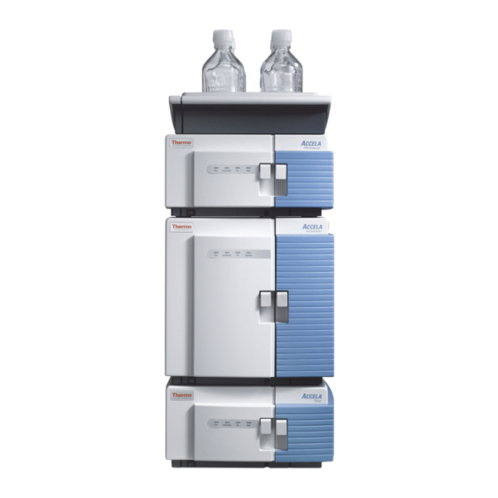
Introduction The Accela UV/Vis Plus Detector (see Figure 1) is a member of the Accela family of UHPLC instruments. Contents • Functional Description • LightPipe Flow Cells • Lamps • Front and Back Panels • Status LEDs • Specifications Figure 1. -
Page 18: Functional Description
UV or visible ranges. The UV/Vis detector is a benchtop unit for inclusion into the Accela LC System. You control the detector remotely over an Ethernet communications link from a Thermo Scientific data system computer. The UV/Vis detector consists of a dual light source, an optical bench (see... -
Page 19: Lightpipe Flow Cells
10 mm LightPipe flow cell schematic Alignment slot (top) Inlet port Outlet port On the 50 mm LightPipe flow cell, the inlet port is on the bottom and the outlet port is on the top (Figure Thermo Scientific Accela UV/Vis Detector Hardware Manual... - Page 20 LightPipe flow cell, wear clean, talc-free gloves. Figure 5. End of the LightPipe flow cell Optical fiber Tubing port Figure 6. 50 mm LightPipe flow cell with protective end caps Protective end caps Accela UV/Vis Detector Hardware Manual Thermo Scientific...
-
Page 21: Lamps
The deuterium lamp has a lifetime of approximately 2000 hours and the tungsten lamp has a lifetime of approximately 2500 hours. Lamp lifetime varies depending on the application. Thermo Scientific Accela UV/Vis Detector Hardware Manual... -
Page 22: Front And Back Panels
U.S. patents: 60057-60144 Part No: 5,608,517 61010 - 1 1 cm Flow Cell / 3.12 Options/Firmware: Line 100V 115V 230V 50/60Hz Fuse T2.5A T1.25A 225VA Power Fuse holder receptacle Accela UV/Vis Detector Hardware Manual Thermo Scientific... -
Page 23: Status Leds
+10 to +40 °C Storage temperature – 40 to +70 °C Fuse size • For 100/115 Vac: T2.5 A (slo-blo) • For 230 Vac: T1.25 A (slo-blo) Operating humidity 5 to 95% non-condensing relative humidity Thermo Scientific Accela UV/Vis Detector Hardware Manual... - Page 24 Analog outputs (2) Unattenuated at 10 mV/AU, 100 mV/AU, or 1.0 V/AU Remote controls Start, Zero, RJ-45 Ethernet interface for a Thermo Scientific data system According to ASTM E1657-98 “Standard Practice for Testing Variable-Wavelength Photometric Detectors Used in Liquid Chromatography”...
-
Page 25: Installation
Checking the Power Setting and Fuses • Installing the LightPipe Flow Cell • Installing the Standard Analytical Flow Cell • Making the Back Panel Connections • Turning On the UV/Vis Detector for the First Time Thermo Scientific Accela UV/Vis Detector Hardware Manual... -
Page 26: Installation Checklist
Check the power settings and fuses. Connect and install the LightPipe flow cell. Make the back panel connections. Turn on the UV/Vis detector for the first time. This UV/Vis detector was installed by: (Name) (Date) Accela UV/Vis Detector Hardware Manual Thermo Scientific... -
Page 27: Unpacking And Inspecting The Uv/Vis Detector
“LightPipe Flow Cell Kits” page Note Before you install the software driver for the UV/Vis detector, you must first install the Thermo Scientific data system. Placement and Environmental Requirements Place the UV/Vis detector on a benchtop as close as possible to the chromatographic column outlet. -
Page 28: Installation Tools
(see Figure 11) and push to the right until the fuse holder pops out. Figure 11. Power entry module Cut-out window 2. Pull the fuse holder out (see Figure 12). Accela UV/Vis Detector Hardware Manual Thermo Scientific... - Page 29 IMPORTANT Do not connect the power cord or turn on the detector yet. Wait until you perform the procedure in “Turning On the UV/Vis Detector for the First Time” page 37 to connect the power cord. Thermo Scientific Accela UV/Vis Detector Hardware Manual...
-
Page 30: Installing The Lightpipe Flow Cell
CAUTION Do not touch the ends of the LightPipe flow cell. This could damage the sensitive optics. If you must grasp the ends of the flow cell to remove it from the assembly, use clean, talc-free gloves. Accela UV/Vis Detector Hardware Manual Thermo Scientific... - Page 31 Tip For best results, when you run the system at a low backpressure, use a backpressure regulator to prevent bubble formation in the detector’s LightPipe flow cell. Thermo Scientific Accela UV/Vis Detector Hardware Manual...
-
Page 32: Mounting The Lightpipe Flow Cell
Using the 1/8 in. ball-end hex screwdriver (supplied), unscrew the flow cell cover retaining screw (see Figure 16). Figure 16. Flow cell cover retaining screw Flow cell cover retaining screw b. Pull the flow cell cover forward and away from the front panel. Accela UV/Vis Detector Hardware Manual Thermo Scientific... - Page 33 Pull the flow cell retaining block to the left and off the retaining bar. Without the supporting retaining block, the retaining bar drops down and rests on the bottom of the retaining block (see Figure 19). Thermo Scientific Accela UV/Vis Detector Hardware Manual...
- Page 34 3 Figure 4 page 4) as you insert it into the mounting assembly. c. Put the retaining bar down into the alignment slot in the flow cell (see Figure 21 Figure 22). Accela UV/Vis Detector Hardware Manual Thermo Scientific...
- Page 35 6. Reinstall the flow cell retaining block as follows: a. Align the retaining block with the notch in the base of the assembly (see Figure 23). Figure 23. Retaining block in place Notch Thermo Scientific Accela UV/Vis Detector Hardware Manual...
- Page 36 Guide the tubing through the slots in the top and bottom of the flow cell compartment cover (see Figure 25). Figure 25. Tubing slots in the flow cell compartment cover Outlet tubing Flow cell cover retaining screw Inlet tubing Accela UV/Vis Detector Hardware Manual Thermo Scientific...
-
Page 37: Installing The Standard Analytical Flow Cell
4 “Mounting the LightPipe Flow Cell” page 4. Remove the LightPipe flow cell mounting assembly as follows: a. Unscrew the tubing clamp thumbscrew (see Figure 26) and set the tubing clamp aside. Thermo Scientific Accela UV/Vis Detector Hardware Manual... - Page 38 Figure 27). 5. Store the LightPipe flow cell mounting assembly in a secure place for possible future use. The mounting area is now ready for the standard analytical flow cell (see Figure 28). Accela UV/Vis Detector Hardware Manual Thermo Scientific...
- Page 39 Flow cell mounting screws Standoffs c. Position the photodiode assembly with the mounting holes aligned with the two standoffs on the flow cell assembly (see Figure 29), and using a 3/32 in. ball-end hex Thermo Scientific Accela UV/Vis Detector Hardware Manual...
- Page 40 10-32, 0.75 in. diameter × 0.5 in. length thumbscrew fS in the accessory kit (see Figure 32). Accela UV/Vis Detector Hardware Manual Thermo Scientific...
-
Page 41: Making The Back Panel Connections
“Connecting the System Interconnect Cable or Cables.” If you are using an autosampler that is not controlled from your Thermo Scientific data system, use the remote communications pins on the detector’s back panel to trigger the detector as described in “Making Remote Communications Connections.”... -
Page 42: Connecting To The Data System Computer
2. Connect the Ethernet switch to the data system computer with a supplied Ethernet cable. Figure 33. Ethernet connections Solvent platform Ethernet port Accela UV/Vis Detector 8-pin receptacle for the interconnect cable Accela Autosampler Computer ENET Accela pump CAT5 shielded Ethernet Ethernet cables switch USB cable Accela UV/Vis Detector Hardware Manual Thermo Scientific... -
Page 43: Setting The Unit Id
For an LC system with an Accela Autosampler, an Accela pump (all models), an Accela UV/Vis Detector, and an optional MS detector, use the system interconnect cable shown in Figure 35 to make the contact closure connections. Thermo Scientific Accela UV/Vis Detector Hardware Manual... - Page 44 Figure 3. To connect an Accela pump (all models), plug a connector labeled PUMP into the 8-pin receptacle on the back panel of the pump. Accela UV/Vis Detector Hardware Manual Thermo Scientific...
- Page 45 1 2 3 4 5 6 7 8 9 10 11 12 13 14 15 16 UNIT ID ENET Accela Autosampler Connector labeled Connector labeled PUMP PUMP RS232 1 2 3 4 5 6 7 8 Accela pump DIGITAL I/O Thermo Scientific Accela UV/Vis Detector Hardware Manual...
- Page 46 Figure 37. Accela Open Autosampler interconnect cable (P/N 60157-63024) 102 cm (40 in.) TO PUMP 60157-63024 TO A/S TO MSQ/LTQ/LXQ 305 cm (120 in.) Figure 38 shows the adapter cable for an Accela detector. Accela UV/Vis Detector Hardware Manual Thermo Scientific...
- Page 47 Accela Open Autosampler, Accela 600 or 1250 Pump, and Accela UV/Vis Detector. Figure 40 shows the contact closure connections for a stand-alone Accela LC system with an Accela Open Autosampler, Accela Pump, and Accela UV/Vis Detector. Thermo Scientific Accela UV/Vis Detector Hardware Manual...
- Page 48 1 2 3 4 5 6 7 8 9 10 11 12 13 14 15 16 UNIT ID ENET RS232 Accela UV/Vis Detector D-SUB25 Accela 600 Pump –or– Accela 1250 Pump TO PUMP Accela UV/Vis Detector Hardware Manual Thermo Scientific...
- Page 49 1 2 3 4 5 6 7 8 9 10 11 12 13 14 15 16 UNIT ID ENET RS232 Accela UV/Vis Detector Accela Pump adapter cable Accela Pump 60157-63022 TO PUMP 1 2 3 4 5 6 7 8 Thermo Scientific Accela UV/Vis Detector Hardware Manual...
-
Page 50: Connecting The Analog Outputs
UV/Vis detector to other data collection devices. Note You must use a Thermo Scientific data system (or equivalent) to control the UV/Vis detector. When the detector is under the control of a Thermo Scientific data system, you can convert the analog output signals with an analog-to-digital converter and process the data with a third-party data system. -
Page 51: Setting The Analog Output Voltage
• If your LC system contains a manual injector or another type of autosampler, connect the RUN input on the UV/Vis detector to the autosampler’s Inject Out output, and connect the GND terminal on the UV/Vis detector to the autosampler’s ground terminal. Thermo Scientific Accela UV/Vis Detector Hardware Manual... - Page 52 You can use either ground terminal for digital input or output return connections. ZERO Input Signal The UV/Vis detector does not use the ZERO connection. EVENT Output Signal Thermo Scientific data systems do not support this output signal. Accela UV/Vis Detector Hardware Manual Thermo Scientific...
-
Page 53: Turning On The Uv/Vis Detector For The First Time
4. Plug the power cord into the power receptacle on the back panel of the detector (see Figure 9 page 6) and connect it to the power source. 5. Turn the power on by pushing in the power switch on the front panel (see Figure 8 page Thermo Scientific Accela UV/Vis Detector Hardware Manual... -
Page 55: Routine Maintenance
To maintain your UV/Vis detector, follow the routine maintenance procedures in this chapter. Contents • Recommended Routine Maintenance • Preventive Maintenance • Tools Required • Cleaning the External Surfaces of the Detector • LightPipe Flow Cell Maintenance • Lamp Maintenance • Replacing the Fuses Thermo Scientific Accela UV/Vis Detector Hardware Manual... -
Page 56: Recommended Routine Maintenance
20 Hz. Tungsten (W) Every 2500 hours or as required. See “Lamp Maintenance” page Flushing the flow cell with clean solvent after every use will reduce how often you need to clean it. Accela UV/Vis Detector Hardware Manual Thermo Scientific... -
Page 57: Preventive Maintenance
Keep the external surfaces of the detector clean and dry. To clean the outside of the detector, wipe it with a dust-free cloth or a damp cloth (moistened with water only) to remove dirt or stains. Thermo Scientific Accela UV/Vis Detector Hardware Manual... -
Page 58: Lightpipe Flow Cell Maintenance
1. Open the front doors of the detector. 2. Using the 1/8 in. ball-end hex screwdriver (supplied), unscrew the flow cell cover retaining screw (see Figure 43). Figure 43. Flow cell cover retaining screw Flow cell cover retaining screw Accela UV/Vis Detector Hardware Manual Thermo Scientific... - Page 59 5. Move the photodiode assembly forward to maximize the space behind it to install the LightPipe flow cell. 6. Loosen and remove the thumbscrew holding the retaining bar to the flow cell retaining block (see Figure 45). Thermo Scientific Accela UV/Vis Detector Hardware Manual...
- Page 60 Routine Maintenance LightPipe Flow Cell Maintenance Figure 45. Flow cell mounting assembly Thumbscrew Retaining block 7. Remove the flow cell retaining block (see Figure 46). Figure 46. Retaining block removed Retaining bar Accela UV/Vis Detector Hardware Manual Thermo Scientific...
-
Page 61: Storing The Lightpipe Flow Cell
Scientific field service engineer with any questions about LightPipe flow cell maintenance or service. To clean the LightPipe flow cell, follow these procedures: • Cleaning the LightPipe Flow Cell with Organic Solvents • Cleaning the LightPipe Flow Cell with Nitric Acid Thermo Scientific Accela UV/Vis Detector Hardware Manual... -
Page 62: Cleaning The Lightpipe Flow Cell With Organic Solvents
(especially methanol). Be sure to wear protective clothing and eye protection and adhere to your company’s safety procedures for the proper handling and disposal of corrosive acids. Flush the flow cell with water to remove all traces of alcohol before flushing it with nitric acid. Accela UV/Vis Detector Hardware Manual Thermo Scientific... - Page 63 Monitor the pH of the outlet stream of the flow cell to ensure that the acid has been completely flushed out. For instructions on reinstalling the flow cell, see “Installing the LightPipe Flow Cell” page Thermo Scientific Accela UV/Vis Detector Hardware Manual...
-
Page 64: Lamp Maintenance
To access the deuterium lamp chronometer and replace the lamp if necessary, follow these procedures: • Accessing the Deuterium Lamp and Reading Its Chronometer • Removing the Deuterium Lamp • Installing a New Deuterium Lamp Accela UV/Vis Detector Hardware Manual Thermo Scientific... - Page 65 4. Pull the cover off to expose the lamp assemblies. Because intense UV light can damage your eyes, the lamps automatically turn off when you turn off the detector or remove the lamp cover. Thermo Scientific Accela UV/Vis Detector Hardware Manual...
- Page 66 1. Remove the deuterium lamp cover as described in “Accessing the Deuterium Lamp and Reading Its Chronometer” page 2. Gently unplug the deuterium lamp lead from the detector (see Figure 51). Take care not to twist the connector. Accela UV/Vis Detector Hardware Manual Thermo Scientific...
- Page 67 1. Remove the used deuterium lamp as described in “Removing the Deuterium Lamp” page 2. Hold the deuterium lamp assembly so that the leads are at the top. 3. Slide the assembly onto the alignment pin (see Figure 52). Thermo Scientific Accela UV/Vis Detector Hardware Manual...
-
Page 68: Replacing The Tungsten Lamp
CAUTION Turn the detector off and unplug the power cord from the power receptacle on the back panel. 2. Open the front doors of the detector. Accela UV/Vis Detector Hardware Manual Thermo Scientific... - Page 69 Figure 53. Tungsten lamp assembly Tungsten lamp Thumbscrew connector Tungsten lamp assembly 6. Loosen and remove the thumbscrew that holds the lamp assembly in place. 7. Pull the assembly straight out and remove it from the detector. Thermo Scientific Accela UV/Vis Detector Hardware Manual...
- Page 70 2. Hold the lamp assembly so that the leads are at the top. Slide the assembly onto the two alignment pins shown in Figure 55. The alignment pins are located on either side of the detector monochromator aperture. Figure 55. Alignment pins for the tungsten lamp Alignment pins Accela UV/Vis Detector Hardware Manual Thermo Scientific...
-
Page 71: Replacing The Fuses
(see Figure 56) and push to the right. The fuse holder pops out. Figure 56. Power entry module 3. Pull the fuse holder out (see Figure 57). Figure 57. Fuse holder Fuse holder Thermo Scientific Accela UV/Vis Detector Hardware Manual... - Page 72 4. Remove the fuses from the fuse holder (see Figure 58) and replace them with new ones. Figure 58. Fuses in the fuse holder 5. Slide the fuse holder back into the power entry module until you hear a click. Accela UV/Vis Detector Hardware Manual Thermo Scientific...
-
Page 73: Troubleshooting
To aid in troubleshooting errors, Table 7 lists some common error messages and numeric codes. Contents • Detector-Related Problems • Error Messages Thermo Scientific Accela UV/Vis Detector Hardware Manual... -
Page 74: Detector-Related Problems
(UL, TÜV, SEMKO, DEMKO, and so on). Ambient light Install the flow cell cover. You must install the flow cell cover before turning the power on. Never remove it when you are acquiring data. Accela UV/Vis Detector Hardware Manual Thermo Scientific... - Page 75 Increase the flow rate until the bubble is removed. Connect a backpressure device to the flow cell outlet (check backpressure rating to avoid rupturing flow cell). Excessive temperature fluctuations Remove the system from drafts. Thermostatically control the column temperature. Thermo Scientific Accela UV/Vis Detector Hardware Manual...
- Page 76 Check the software to determine the nature of amber the error, or begin the run again. Lamps LED is amber Both lamps are off Turn on the lamps and allow 1.5 hours for warm-up. Accela UV/Vis Detector Hardware Manual Thermo Scientific...
-
Page 77: Error Messages
Sample diode failed (Could be exposed to light.) 2025 Wavelength home test failed 2026 Second wavelength home failed 2027 Analog linearity test failed 2028 D2 lamp failed/not present 2029 W lamp failed/not present 2030 Shutter failed 2031 Unknown shutter/lamp failure Thermo Scientific Accela UV/Vis Detector Hardware Manual... - Page 78 Invalid auto zero time 2227 Invalid rise time filter 2228 Invalid run time 2232 Invalid runs per wavelength 2234 Invalid offset 2235 Invalid zero on lambda change value 2236 Invalid channel 2 selection Accela UV/Vis Detector Hardware Manual Thermo Scientific...
-
Page 79: Appendix A Accessories And Replaceable Parts
Ferrule, 1/4-28, ETFE 3256-0022 Upchurch™ Fingertight II fitting (Upchurch P/N F-200) 1 A3469-020 LC Test Mix, 1 mL F3012-010 Funnel F5034-010 Tubing, convoluted, detector drain 5101-1857 Fuse, slo-blo, for 230 V applications (T1.25 A) Thermo Scientific Accela UV/Vis Detector Hardware Manual... -
Page 80: Lightpipe Flow Cell Kits
Fingertight, 10-32, one-piece PEEK fitting 803260 Inlet tubing, with insulation, PEEK 1/16 in. OD × 0.005 in. ID (red), 33 in. length 703950 Outlet tubing, PEEK 1/16 in. OD × 0.01 in. ID (blue), 60 in. Accela UV/Vis Detector Hardware Manual Thermo Scientific... -
Page 81: Standard Analytical Flow Cell Parts
Part number Description 9551-0023 Deuterium (D2) lamp assembly (pre-aligned) 9551-0022 Tungsten (W) lamp assembly (pre-aligned) 5101-1857 Fuse, slo-blo, for 230 V applications (T1.25 A) 5101-1858 Fuse, slo-blo, for 100/115 V applications (T2.5 A) Thermo Scientific Accela UV/Vis Detector Hardware Manual... -
Page 82: Service Spare Parts
Accessories and Replaceable Parts Service Spare Parts Service Spare Parts Table 13 lists service spare parts for the Accela UV/Vis Plus Detector. Table 13. Service spare parts Part number Description 60053-61081R Analog PCB 60053-63010 Analog PCB cable 60053-61080R Converter PCB... -
Page 83: Index
Ethernet system interconnect electrical interference, causes of Accela Autosampler electromagnetic compatibility Accela Open Autosampler EMC compliance chromatograms, acquiring with an A/D converter error messages column bleed external surfaces, cleaning compliance regulatory WEEE Thermo Scientific Accela UV/Vis Detector Hardware Manual... - Page 84 10 mm Light Pipe 50 mm Light Pipe storing temperature fluctuations, results of linearity tools installation maintenance troubleshooting maintenance detector problems preventive Status page error messages recommendations for tools multiple detectors, placement Accela UV/Vis Detector Hardware Manual Thermo Scientific...
- Page 85 Index: U tungsten lamp description installing lifetime removing uninterruptible power supply (UPS) unit ID, setting voltage ac line problems voltage selector warm-up time wavelength accuracy and range WEEE compliance weight, detector Thermo Scientific Accela UV/Vis Detector Hardware Manual...
Need help?
Do you have a question about the Accela UV/Vis Plus and is the answer not in the manual?
Questions and answers