
Related Manuals for Thermo Scientific VC-D60


Summary of Contents for Thermo Scientific VC-D60
- Page 1 Vanquish Refractive Index Detector VC-D60 Operating Manual 4820.6001-EN Revision 1.0 • May 2023 *4820.6001-EN-1.0*...
- Page 2 Copyright © 2023 Thermo Fisher Scientific Inc. All rights reserved. Original Operating Manual The hardware descriptions in this manual revision refer to devices: VC-D60-A. Trademarks Acrobat, Adobe, and Adobe Reader are trademarks of Adobe Systems Incorporated. Microsoft and Windows are trademarks of Microsoft Corporation.
- Page 3 Contact Us on http://www.thermofisher.com. Technical Assistance For technical support for HPLC products, contact your local Thermo Fisher Scientific support organization. For contact information, go to Contact Us on http://www.thermofisher.com. Refractive Index Detector (VC-D60) Page 3 Operating Manual...
- Page 4 Contacting Us Page 4 Refractive Index Detector (VC-D60) Operating Manual...
-
Page 5: Table Of Contents
Allowed pH Ranges................... 25 2.5.3 Allowed Concentrations ................ 26 2.5.4 Solvent Recommendations .............. 26 2.5.5 Further Information ................. 27 3 Device Overview................. 29 Detector Features .................... 30 Operating Principle .................... 31 Interior Components.................... 35 Refractive Index Detector (VC-D60) Page 5 Operating Manual... - Page 6 5.10 Turning On the Device .................. 67 6 Operation................... 69 Introduction to this Chapter ................ 70 Safety Guidelines for Operation................ 71 General Guidelines for Operation................ 72 Control Elements .................... 73 6.4.1 Keypad...................... 73 6.4.2 Status Indicators.................. 74 Page 6 Refractive Index Detector (VC-D60) Operating Manual...
- Page 7 General Information about Troubleshooting............. 108 Messages...................... 109 Operating Issues.................... 111 8.3.1 Resolving Liquid Leaks................ 111 8.3.2 Additional Device Operating Issues............ 111 9 Specifications ................ 115 Performance Specifications ................ 116 Physical Specifications .................. 118 Refractive Index Detector (VC-D60) Page 7 Operating Manual...
- Page 8 11.1 Compliance Information .................. 126 11.1.1 Declarations of Conformity .............. 126 11.1.2 WEEE Compliance .................. 127 11.1.3 FCC Compliance.................. 127 11.1.4 Manual Release History................ 128 11.2 Analog I/O Pin Assignment ................ 129 Index .................. 131 Page 8 Refractive Index Detector (VC-D60) Operating Manual...
-
Page 9: Using This Manual
Using this Manual 1 Using this Manual This chapter provides information about this manual, the conventions used throughout the manual, and the reference documentation that is available in addition to this manual. Refractive Index Detector (VC-D60) Page 9 Operating Manual... -
Page 10: About This Manual
The descriptions in this manual assume that the device is installed in the Vanquish system stack. If this is not the case, additional hardware is required and must be ordered separately. The information in this manual applies correspondingly. Page 10 Refractive Index Detector (VC-D60) Operating Manual... -
Page 11: Conventions
Highlights information necessary to prevent damage to the device or invalid test results. TIP Highlights information of general interest or helpful information that can make a task easier or optimize the performance of the device. Refractive Index Detector (VC-D60) Page 11 Operating Manual... -
Page 12: Typographical Conventions
The electronic version (PDF) of the manual contains numerous links that you can click to go to other locations within the manual. These include: • Table of contents entries • Index entries • Cross-references (in blue text) Page 12 Refractive Index Detector (VC-D60) Operating Manual... -
Page 13: Reference Documentation
For information about the main elements of the user interface and step-by-step guidance through the most important workflows, refer to the Quick Start Guide. • Reference Card For a concise overview of the most important workflows, refer to the Reference Card. Refractive Index Detector (VC-D60) Page 13 Operating Manual... - Page 14 TIP The Chromeleon Help and documents are included in the software shipment. Third-Party Documentation Refer also to the user documentation provided by the manufacturers of third-party components and materials, for example, Safety Data Sheets (SDSs). Page 14 Refractive Index Detector (VC-D60) Operating Manual...
-
Page 15: Safety
• Safety 2 Safety This chapter provides general and specific safety information and informs about the intended use of the device. Refractive Index Detector (VC-D60) Page 15 Operating Manual... -
Page 16: Safety Symbols And Signal Words
Always keep the manual near the device for quick reference. • Save this manual and pass it on to any subsequent user. Read, understand, and comply with all safety messages and precautionary statements presented in this manual. Page 16 Refractive Index Detector (VC-D60) Operating Manual... -
Page 17: Safety Symbols On The Device
TIP An additional type label on the leak tray of the device indicates the module name, serial number, part number, and revision number (if any). To facilitate device identification, have the information from this label available when communicating with Thermo Fisher Scientific. Refractive Index Detector (VC-D60) Page 17 Operating Manual... -
Page 18: Intended Use
Regularly running calibration • Establishing shelf life limits and following them for all consumables used with the system • Running the system according to the laboratory's verified and validated 'lab developed test' protocol Page 18 Refractive Index Detector (VC-D60) Operating Manual... -
Page 19: Safety Precautions
Thermo Fisher Scientific before proceeding. Safety Standard This device is a Safety Class I instrument (provided with terminal for protective grounding). The device has been manufactured and tested according to international safety standards. Refractive Index Detector (VC-D60) Page 19 Operating Manual... -
Page 20: Qualification Of The Personnel
Protective Clothing To protect you from chemical splashes, harmful liquids, or other contamination, put on appropriate protective clothing, such as a lab coat. Page 20 Refractive Index Detector (VC-D60) Operating Manual... -
Page 21: Electrical Safety Precautions
Do not place liquid reservoirs directly upon the device. Liquid might leak into the device and get into contact with electronic components causing a short circuit. Instead, place liquid reservoirs in the solvent rack that is available for the Vanquish system. Refractive Index Detector (VC-D60) Page 21 Operating Manual... -
Page 22: General Residual Hazards
Wear personal protective equipment as required by the hazard and follow good laboratory practice. • Dispose of biohazardous waste in an environmentally safe manner that is consistent with local regulations. Follow a regulated, approved waste disposal program. Page 22 Refractive Index Detector (VC-D60) Operating Manual... -
Page 23: In Case Of Emergency
Prevent the generation of static electricity near the chromatography system. 2.3.6 In Case of Emergency WARNING—Safety Hazard In case of emergency, disconnect the device from the power line. Refractive Index Detector (VC-D60) Page 23 Operating Manual... -
Page 24: Compliance Information
Thermo Fisher Scientific or one of its authorized representatives. The device has been shipped from the manufacturing site in a safe condition. See also Compliance Information (} page 126) Page 24 Refractive Index Detector (VC-D60) Operating Manual... -
Page 25: Solvent And Additive Information
• Mobile phases containing ammonium hydroxide: In rare cases, a shortened lifetime of reversed-phase (UHMW-PE) piston seals has been observed with high pH, ammonium hydroxide containing mobile phases and prolonged exposure. Refractive Index Detector (VC-D60) Page 25 Operating Manual... -
Page 26: Allowed Concentrations
If a solvent listed below is in use, flush out all the flow path sufficiently with an inert solvent that is compatible with your chromatographic system. Buffers, acids, and other highly ionic aqueous solutions should be flushed out with large amounts of Page 26 Refractive Index Detector (VC-D60) Operating Manual... -
Page 27: Further Information
• Observe the general guidelines and recommendations on the use of solvents and additives in the chromatography system. Refer to Use of Solvents and Additives in the Vanquish System Operating Manual. Refractive Index Detector (VC-D60) Page 27 Operating Manual... - Page 28 • Safety Page 28 Refractive Index Detector (VC-D60) Operating Manual...
-
Page 29: Device Overview
• Device Overview 3 Device Overview This chapter introduces you to the device and the main components. Refractive Index Detector (VC-D60) Page 29 Operating Manual... -
Page 30: Detector Features
• Stable baselines with a maximum drift of 0.2 µRIU/h or less and with a maximum noise of 2.5 nRIU or less • Flow cell temperature stabilization by active heating for improved baseline signal Page 30 Refractive Index Detector (VC-D60) Operating Manual... -
Page 31: Operating Principle
Figure 1: Snell’s Law Character Description index of refraction angle of incidence angle of refraction velocity of light in first medium velocity of light in second medium Refractive Index Detector (VC-D60) Page 31 Operating Manual... - Page 32 As long as no difference exists between the refractive indices of the media of the two cells, there is no refraction of the light passing through them. Page 32 Refractive Index Detector (VC-D60) Operating Manual...
- Page 33 Additional circuitry enables the user to easily correct the signal output to electronic zero. Ns = Nr Ns > Nr Figure 4: Photo sensors Description Photo sensor A Photo sensor B Light beam Refractive Index Detector (VC-D60) Page 33 Operating Manual...
- Page 34 This difference gives a signal having both amplitude and polarity. Page 34 Refractive Index Detector (VC-D60) Operating Manual...
-
Page 35: Interior Components
Keypad with status indicators Flow cell inlet and outlet Capillary clip Leak tray with leak sensor Type label, indicating the module name, serial number, part number, and re- vision number (if any) Leak sensor Refractive Index Detector (VC-D60) Page 35 Operating Manual... -
Page 36: Leak Detection
When the leak sensor detects leakage, the status indicators change to red and beeping starts to alert you. Follow the instructions in this manual to find and eliminate the source for the leakage. Page 36 Refractive Index Detector (VC-D60) Operating Manual... -
Page 37: Operation
Chromeleon Help. Other data systems may support operation of this device. In this case, installation of additional software may be required. For details, contact the Thermo Fisher Scientific sales organization. Refractive Index Detector (VC-D60) Page 37 Operating Manual... - Page 38 • Device Overview Page 38 Refractive Index Detector (VC-D60) Operating Manual...
-
Page 39: Unpacking
• Unpacking 4 Unpacking This chapter provides information for unpacking the device and informs you about the scope of delivery. Refractive Index Detector (VC-D60) Page 39 Operating Manual... -
Page 40: Unpacking
2. Remove the ship kit from the shipping container. 3. Remove the device from the shipping container: Grasp the device by the carrying handles. Slowly and carefully, lift the device out of the shipping container. Page 40 Refractive Index Detector (VC-D60) Operating Manual... - Page 41 8. Some surfaces including the doors of the device are covered by a protective film during shipment. Remove the protective film from all surfaces as applicable. Refractive Index Detector (VC-D60) Page 41 Operating Manual...
-
Page 42: Scope Of Delivery
Ship Kit • Operating manual (downloadable from customer manual web site) • Power cord For information on contents of the ship kit or reordering parts, see Accessories, Consumables and Replacement Parts (} page 119). Page 42 Refractive Index Detector (VC-D60) Operating Manual... -
Page 43: Installation
Installation 5 Installation This chapter specifies the requirements for the installation site and describes how to set up, install, and configure the device in the Vanquish system and in the chromatography software. Refractive Index Detector (VC-D60) Page 43 Operating Manual... -
Page 44: Installing The Detector (Overview)
Setting Up the Flow Connections (} page 58) ↓ Set up the device in the software Setting Up the Device in the Software (} page 65) ↓ Turn on the device Turning On the Device (} page 67) ↓ Page 44 Refractive Index Detector (VC-D60) Operating Manual... - Page 45 Recommended: Perform Instrument Installation Qualification On the Chromeleon 7 Console, click Tools > Instrument Qualification > Installation Qualification. ↓ Recommended: Perform Operational Qualification On the Chromeleon 7 Console, click Tools > Instrument Qualification > Operational Qualification. Refractive Index Detector (VC-D60) Page 45 Operating Manual...
-
Page 46: Safety Guidelines For Installation
Always unplug the power cord before starting repair work inside the device. • If you were instructed to remove any housing covers or panels, do not connect the power cord to the device while the cover or panels are removed. Page 46 Refractive Index Detector (VC-D60) Operating Manual... -
Page 47: Site Requirements
The end of the power cords that plugs into the power socket on the device is identical for all power cords. The end of the power cords that plugs into the wall socket is different. Refractive Index Detector (VC-D60) Page 47 Operating Manual... -
Page 48: Condensation
If you suspect that condensation is present, allow the device to warm up to room temperature. This may take several hours. Wait until the condensation is gone completely before connecting the device to the power line. Page 48 Refractive Index Detector (VC-D60) Operating Manual... -
Page 49: Accessing The Interior Components
To access the interior components in the device, open the front doors. To allow easy access from the front, the flow connections of the device are located directly behind the doors. Figure 8: Opening the front doors Refractive Index Detector (VC-D60) Page 49 Operating Manual... -
Page 50: System Arrangement
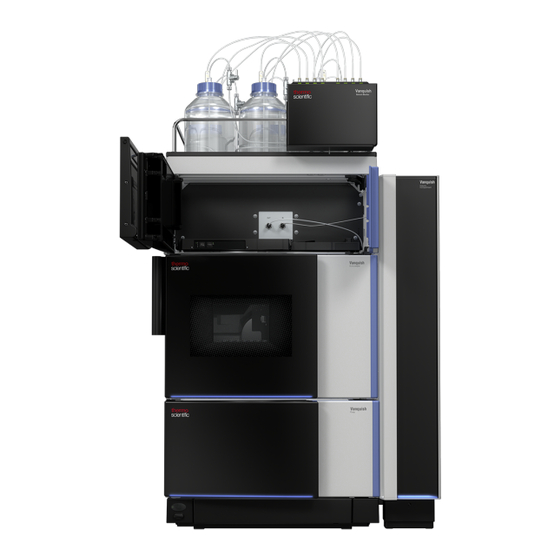
UV/VIS detector. For instructions on how to set up the system stack, refer to the Vanquish System Operating Manual. Page 50 Refractive Index Detector (VC-D60) Operating Manual... - Page 51 • Installation System with Single Detector Figure 9: Vanquish system, standard configuration (example) Description Solvent rack Refractive index detector Autosampler Pump System base Column compartment Refractive Index Detector (VC-D60) Page 51 Operating Manual...
- Page 52 • Installation System with Refractive Index Detector as Second Detector Figure 10: Vanquish system, configuration with two detectors (example) Description Solvent rack Refractive index detector UV/VIS detector Autosampler Pump System base Column compartment Page 52 Refractive Index Detector (VC-D60) Operating Manual...
-
Page 53: Loosening The Locking Screws
2. Loosen the 2 screws by 2 turns each. Do not fully remove them. Figure 11: Loosening the locking screws 3. Install the slide-in module (see Installing the Slide-In Module (} page 103)). Refractive Index Detector (VC-D60) Page 53 Operating Manual... -
Page 54: Connecting The Device
USB (Universal Serial Bus) port ("B"-type connector): Allows connection to the computer on which the data management system is installed, such as the Chromeleon software. System interlink port: Allows power on/off control for the detector from the system base. Page 54 Refractive Index Detector (VC-D60) Operating Manual... - Page 55 Vanquish system. For instructions, see Connecting Cables in a One- Detector-Configuration (} page 56) Connecting Cables in a Two- Detector Configuration (} page 56). 2. Connect the power cord (see Connecting the Power Cord (} page 57)). Refractive Index Detector (VC-D60) Page 55 Operating Manual...
-
Page 56: Connecting Cables In A One-Detector-Configuration
2. Connect a system interlink cable from the free System Interlink port on the diode array detector to the refractive index detector. 3. Connect a system interlink cable from the free System Interlink port on the refractive index detector to the column compartment. Page 56 Refractive Index Detector (VC-D60) Operating Manual... -
Page 57: Connecting The Power Cord
1. Verify that the power switch on the device is set to OFF. 2. Connect the power cord to the power inlet connector on the device. 3. Connect the free end of the power cord to an appropriate power source. Refractive Index Detector (VC-D60) Page 57 Operating Manual... -
Page 58: Setting Up The Flow Connections
Connect the waste line to the flow cell only as described in the manual. • Do not discharge waste from the flow cell through the open leakage drain system of the Vanquish system. Page 58 Refractive Index Detector (VC-D60) Operating Manual... -
Page 59: Connecting Fittings, Capillaries, And Tubing
Connecting Viper Capillaries This section describes how to connect Viper™ capillaries. All Viper flow connections in the Vanquish system are designed to be finger-tight. To connect Viper capillaries with knurls, follow these steps: Refractive Index Detector (VC-D60) Page 59 Operating Manual... - Page 60 2. If leakage continues, remove the capillary. 3. Clean the capillary ends carefully by using a lint-free tissue wetted with isopropanol. 4. Reinstall the capillary. 5. If the connection continues to leak, install a new Viper capillary. Page 60 Refractive Index Detector (VC-D60) Operating Manual...
-
Page 61: Connecting The Inlet Capillary
(i.e. peak broadening effects due to extra dispersion volume). 2. Connect the capillary to the flow cell inlet (IN). Refractive Index Detector (VC-D60) Page 61 Operating Manual... - Page 62 UV/VIS detector. Refer to the instructions in the Operating Manual for the UV/VIS detector. 2. Route the connecting capillary from the flow cell outlet of the UV/ VIS detector upward to the refractive index detector. Page 62 Refractive Index Detector (VC-D60) Operating Manual...
-
Page 63: Connecting The Waste Line
(refer to the Vanquish System Operating Manual). 2. Remove the plug from the flow cell outlet. Refractive Index Detector (VC-D60) Page 63 Operating Manual... - Page 64 (refer to the Vanquish System Operating Manual). TIP The waste line should go straight to the system base and to waste. Make sure that the line is positioned straight in the tubing guides. Page 64 Refractive Index Detector (VC-D60) Operating Manual...
-
Page 65: Setting Up The Device In The Software
1. Start the Chromeleon 7 Instrument Configuration Manager. 2. Select the instrument and click Add Module. 3. On the Manufacturers list, select Thermo Scientific HPLC: Vanquish, and on the Modules list, select Vanquish Refractive Index Detector. 4. On the General page, in the COM Port box, select the new virtual COM port (usually the COM port with the highest number). - Page 66 COM port. Try a different COM port and test the connection again. 6. Save the installation and close the Instrument Configuration Manager. Page 66 Refractive Index Detector (VC-D60) Operating Manual...
-
Page 67: Turning On The Device
Turn off the device with the main power switch, when instructed to do so, for example, during maintenance. Pressing the system power button will not be sufficient to turn off the power to the device completely. See also Power On/Off Control (} page 76) Refractive Index Detector (VC-D60) Page 67 Operating Manual... - Page 68 • Installation Page 68 Refractive Index Detector (VC-D60) Operating Manual...
-
Page 69: Operation
• Operation 6 Operation This chapter describes the elements for device control, provides information for routine operation and for shutdown. Refractive Index Detector (VC-D60) Page 69 Operating Manual... -
Page 70: Introduction To This Chapter
Operating Manual. Details on control and operation of the device are available in the Chromeleon Help. Software descriptions in this manual refer to Chromeleon 7. Terminology may be different to that of other software versions. Page 70 Refractive Index Detector (VC-D60) Operating Manual... -
Page 71: Safety Guidelines For Operation
Never expose the fluidic components of the detector to excessive backpressure. Observe the specified pressure rating for the detector (see Performance Specifications (} page 116)). • Avoid clogging of the flow cell or waste line. Refractive Index Detector (VC-D60) Page 71 Operating Manual... -
Page 72: General Guidelines For Operation
Stable backpressure and correct waste line setup ¨ TIP During measurements, avoid touching the module’s front (close the doors) or the electrical connectors as this may impair the measurement signal. Page 72 Refractive Index Detector (VC-D60) Operating Manual... -
Page 73: Control Elements
To turn off the beep for the current alarm, press this button. Eliminate the source for the alarm within 10 minutes. Otherwise, beeping starts again. If the device detects a different problem, beeping alerts you again immediately. Refractive Index Detector (VC-D60) Page 73 Operating Manual... -
Page 74: Status Indicators
An injection, sequence or validation procedure (such as span validation) is running. A problem or error has occurred. For the related message, check the Instrument Audit Trail. For remedial action, see Troubleshooting (} page 107). Page 74 Refractive Index Detector (VC-D60) Operating Manual... - Page 75 A problem or error has occurred. For the related message, check the Instrument Audit Trail. For remedial action, see Troubleshooting (} page 107). For information about the LED that is present next to the PURGE button on the keypad, see Keypad (} page 73). Refractive Index Detector (VC-D60) Page 75 Operating Manual...
-
Page 76: Power On/Off Control
To turn off a device completely, you have to turn it off with the main power switch on the device. Pressing the system power button will not be sufficient to turn off the power to the device completely. Page 76 Refractive Index Detector (VC-D60) Operating Manual... -
Page 77: Preparing The Detector For Operation
3. Perform an Autozero. This may take up to 40 seconds. TIP The chromatography data system supports procedures for automatically starting a chromatography system, including stabilizing the noise and drift signal (Smart Startup). For details, refer to the Chromeleon Help. Refractive Index Detector (VC-D60) Page 77 Operating Manual... -
Page 78: Purging The Flow Cell
20 minutes from the above step. 5. Press or deactivate PURGE again to turn off the valve. Mobile phase solvent flows to the sample cell. 6. Wait until the baseline is stabilized. Page 78 Refractive Index Detector (VC-D60) Operating Manual... -
Page 79: Flow Cell Temperature Setting
• If you select a lower temperature setting than was set before, the stabilization time will take longer compared to setting a higher temperature. Refractive Index Detector (VC-D60) Page 79 Operating Manual... -
Page 80: Shutdown
THF as the solvent. Organohalocarbons, such as methylene Keep a small amount of flow to keep chloride and chloroform down the amount of corrosive chloride impurities in the cell. Page 80 Refractive Index Detector (VC-D60) Operating Manual... - Page 81 If the detector is to be exposed to sub-freezing temperatures, an antifreeze flush, such as methanol must be used. Ideally, you are suggested to expel residual solution out of the detector and to fill the sample and reference cells with isopropanol. Refractive Index Detector (VC-D60) Page 81 Operating Manual...
- Page 82 • Operation Page 82 Refractive Index Detector (VC-D60) Operating Manual...
-
Page 83: Maintenance And Service
• Maintenance and Service 7 Maintenance and Service This chapter describes the routine maintenance and the service procedures that the user may perform. Refractive Index Detector (VC-D60) Page 83 Operating Manual... -
Page 84: Introduction To Maintenance And Service
However, it is possible to remove a door if this should ever be required for a specific reason or procedure. If you need to remove a door, follow the related steps in Replacing the Doors (} page 93). Page 84 Refractive Index Detector (VC-D60) Operating Manual... -
Page 85: Safety Guidelines For Maintenance And Service
Solvents can spray when under high pressure. • Stop the pump flow prior to opening the flow path. • Wait until the system pressure is down to zero. • When opening the flow path, wear appropriate protective equipment. Refractive Index Detector (VC-D60) Page 85 Operating Manual... - Page 86 Always unplug the power cord before starting repair work inside the device. • If you were instructed to remove any housing covers or panels, do not connect the power cord to the device while the cover or panels are removed. Page 86 Refractive Index Detector (VC-D60) Operating Manual...
-
Page 87: Routine And Preventive Maintenance
Decontamination is required, for example, when leakage or spillage has occurred, or before service or transport of the device. Use a suitable cleaning detergent or disinfectant to ensure that the treatment renders the device safe to handle. Refractive Index Detector (VC-D60) Page 87 Operating Manual... - Page 88 If necessary, slightly dampen the cloth or wipe with a solution of lukewarm water and a suitable cleaning detergent. 2. Allow the cleaning detergent to react as recommended by the manufacturer. Page 88 Refractive Index Detector (VC-D60) Operating Manual...
-
Page 89: Performing Span Validation
If span validation was successful, the validation date is updated. If span validation fails, contact Thermo Fisher Scientific Technical Support for assistance. Refractive Index Detector (VC-D60) Page 89 Operating Manual... -
Page 90: Cleaning The Flow Cell
Never put hydrochloric acid in the flow cell. Use diluted (10-20%) or concentrated nitric acid as a cleaning solution instead. • The sample and reference cells should be filled with water or air (blown dry) before proceeding. Page 90 Refractive Index Detector (VC-D60) Operating Manual... - Page 91 Make sure to flush the flow path with deionized water before and after. Apply the nitric acid solution using a syringe and make sure the solution does not stay more than 5 minutes. Refractive Index Detector (VC-D60) Page 91 Operating Manual...
- Page 92 (1) miscible with your mobile phase, (2) a good solvent for the predicted contaminant, and (3) generally of greater polarity than your mobile phase. Page 92 Refractive Index Detector (VC-D60) Operating Manual...
-
Page 93: Replacing The Doors
You can remove the door only when the hinges are in the grooves. Figure 21: Unhinging a door Description Hinge on the housing Reception groove on the door Refractive Index Detector (VC-D60) Page 93 Operating Manual... - Page 94 5. Insert the hinges in the groove, by pushing up and slightly turning the door. 6. Push the door downward to lock it in place. You can close the door only when it is properly installed. Page 94 Refractive Index Detector (VC-D60) Operating Manual...
-
Page 95: Replacing The Main Power Fuses
Do not use repaired fuses and do not short-circuit the fuse holders. Follow these steps The fuse holder is located next to the main power switch. Figure 22: Fuse holder Description Main power switch (on/off control) Fuse holder Power-inlet connector Refractive Index Detector (VC-D60) Page 95 Operating Manual... - Page 96 Always replace both fuses. 3. Reinstall the fuse holder. 4. Reconnect the power cord to the power source and to the device. 5. Turn on the device with the main power switch. Page 96 Refractive Index Detector (VC-D60) Operating Manual...
-
Page 97: Transporting Or Shipping The Detector
2. Turn off the device with its main power switch and disconnect the power cord. 3. Remove all cables and flow connections to other devices. 4. Tighten the locking screws (see Tightening the Locking Screws (} page 98)). Refractive Index Detector (VC-D60) Page 97 Operating Manual... -
Page 98: Tightening The Locking Screws
(} page 101)). Follow these steps 1. Place the slide-in module on an even and clean surface with the bottom side facing up. 2. Gently tighten the 2 screws. Figure 23: Tightening the locking screws Page 98 Refractive Index Detector (VC-D60) Operating Manual... -
Page 99: Transporting The Detector To A New Location
• Fill in and sign the Health and Safety Form. Thermo Fisher Scientific refuses to accept devices for repair if the Health and Safety Form is missing, incompletely filled in, or unsigned. Refractive Index Detector (VC-D60) Page 99 Operating Manual... - Page 100 Thermo Fisher Scientific support organization for the appropriate procedure. Restarting the Device after Shipping To install the device after shipping, follow the instructions on mounting the system stack in the Vanquish System Operating Manual. Page 100 Refractive Index Detector (VC-D60) Operating Manual...
-
Page 101: Replacing The Slide-In Module
Transporting or Shipping the Detector (} page 97). Follow these steps 1. Loosen the four captive screws on the front left and front right of the device. Figure 24: Captive screws on the slide-in module Refractive Index Detector (VC-D60) Page 101 Operating Manual... - Page 102 Place the slide-in module on a clean and stable surface. 5. If the module is transported over a longer distance or if it is shipped: Fasten the locking screws (see Tightening the Locking Screws (} page 98)). Page 102 Refractive Index Detector (VC-D60) Operating Manual...
-
Page 103: Returning The Slide-In Module
Physical handling of the device, including lifting or moving, requires a team effort of two persons. • A team effort is in particular required when lifting the device into the system stack or when removing it. Tools required Screwdriver, Torx T20 Refractive Index Detector (VC-D60) Page 103 Operating Manual... - Page 104 Figure 26: Inserting the slide-in module 4. To facilitate tightening the slide-in module in the enclosure, pull out the module a few millimeters (approximately 2 to 5 mm). Page 104 Refractive Index Detector (VC-D60) Operating Manual...
-
Page 105: Setting Up The Slide-In Module
Refer to the Operating Manuals for the modules. 3. Before starting an analysis, let the chromatography system equilibrate and be sure that it is ready for operation. 4. In the Chromeleon software, run the device-specific Performance Qualification (PQ) tests. Refractive Index Detector (VC-D60) Page 105 Operating Manual... - Page 106 • Maintenance and Service Page 106 Refractive Index Detector (VC-D60) Operating Manual...
-
Page 107: Troubleshooting
• Troubleshooting 8 Troubleshooting This chapter is a guide to troubleshooting issues that may arise during operation of the device. Refractive Index Detector (VC-D60) Page 107 Operating Manual... -
Page 108: General Information About Troubleshooting
The Instrument Audit Trails can be found on the ePanel Set (Audit ePanel). In addition, Audit Trails for each instrument are available in the Chromeleon 7 Console Data view, in the folder of the Instrument. Page 108 Refractive Index Detector (VC-D60) Operating Manual... -
Page 109: Messages
An error occurred during span validation. Verify that the sucrose span value could not be confirmed. solution was prepared as described in Performing Span Validation Please check the used sucrose solution (} page 89). and try again. Refractive Index Detector (VC-D60) Page 109 Operating Manual... - Page 110 V. Please ensure a stable environment and try again. Unstable Temperature The flow cell temperature has not met the preset temperature. For hints regarding temperature setting, see Flow Cell Temperature Setting (} page 79). Page 110 Refractive Index Detector (VC-D60) Operating Manual...
-
Page 111: Operating Issues
This section provides additional issues that may arise during operation of the device. Locate the table for the type of symptom you have, find the possible cause, and use the description of the solution to help you solve your problem quickly. Refractive Index Detector (VC-D60) Page 111 Operating Manual... - Page 112 Cyclic noise Waste line is too • Verify that you have installed the correct waste line at the matching the narrow outlet port. pump stroke • Check the waste line for crimps. frequency Page 112 Refractive Index Detector (VC-D60) Operating Manual...
- Page 113 Intensity alarm Flow cell dirty Clean the reference and sample cells. See Cleaning the Flow Cell (} page 90). Lamp burned out Contact Technical Support. Flow cell empty Fill the flow cell with eluent. Refractive Index Detector (VC-D60) Page 113 Operating Manual...
- Page 114 • Troubleshooting Page 114 Refractive Index Detector (VC-D60) Operating Manual...
-
Page 115: Specifications
• Specifications 9 Specifications This chapter provides the physical and performance specifications, including information about the materials used in the flow path of the device. Refractive Index Detector (VC-D60) Page 115 Operating Manual... -
Page 116: Performance Specifications
All system parameters are logged in the Chromeleon Audit Trail. features Biocompatible 1-13 For details, refer to Allowed pH Ranges (} page 25). Buffer concentration ≤ 1mol/L Chloride concentration ≤ 0.1 mol/L NP compatibility Page 116 Refractive Index Detector (VC-D60) Operating Manual... - Page 117 Materials in the flow path Stainless steel, PTFE, quartz glass Linearity < 5.0% RSD Noise ≤ 2.5 nRIU at retention time 3 s, data collection rate 50 Hz Drift ≤ 200 nRIU/hour at retention time 3 s, data collection rate 50 Hz Refractive Index Detector (VC-D60) Page 117 Operating Manual...
-
Page 118: Physical Specifications
100 – 240 V AC, ± 10 %; 50/60 Hz; max. 250 W / 560 VA Overvoltage category Emission sound pressure level None Dimensions 16 x 42 x 62 cm (height x width x depth) Weight 16.5 kg Page 118 Refractive Index Detector (VC-D60) Operating Manual... -
Page 119: Accessories, Consumables And Replacement Parts
This chapter describes the standard accessories that are shipped with the device and the accessories that are available as an option. This chapter also provides information for reordering consumables and replacement parts. Refractive Index Detector (VC-D60) Page 119 Operating Manual... -
Page 120: General Information
Accessories, consumables, and replacement parts are always maintained at the latest technical standard. Therefore, part numbers are subject to change. If not otherwise stated, updated parts will be compatible with the parts they replace. Page 120 Refractive Index Detector (VC-D60) Operating Manual... -
Page 121: Ship Kit
Tubing bracket USB cable, USB 2.0, high-speed, type A to B, 1m Viper capillary, 350 mm length, stainless steel, I.D. 0.18 mm Waste line For reordering information, see Consumables and Replacement Parts (} page 123). Refractive Index Detector (VC-D60) Page 121 Operating Manual... -
Page 122: Optional Accessories
Accessories, Consumables and Replacement Parts 10.3 Optional Accessories Item Part No. Flushing and injection kit for flow cells, including syringe 6078.4200 Analog I/O cable, 6 pin, for Vanquish Refractive Index Detectors 6060.0006 Page 122 Refractive Index Detector (VC-D60) Operating Manual... -
Page 123: Consumables And Replacement Parts
Power cord, Denmark 6000.1070 Power cord, EU 6000.1000 Power cord, India, SA 6000.1090 Power cord, Italy 6000.1040 Power cord, Japan 6000.1050 Power cord, UK 6000.1020 Power cord, USA 6000.1001 Power cord, Switzerland 6000.1030 Refractive Index Detector (VC-D60) Page 123 Operating Manual... - Page 124 • Accessories, Consumables and Replacement Parts Page 124 Refractive Index Detector (VC-D60) Operating Manual...
-
Page 125: Appendix
• Appendix 11 Appendix This chapter provides additional information about compliance and the I/O pin assignment. Refractive Index Detector (VC-D60) Page 125 Operating Manual... -
Page 126: Compliance Information
For more information, go to http://www.thermofisher.com/us/en/ home/technical-resources/rohs-certificates.html UKCA Declaration of Conformity The device has satisfied the requirements for the UKCA mark and is compliant with the applicable requirements. Page 126 Refractive Index Detector (VC-D60) Operating Manual... -
Page 127: Weee Compliance
Operation of this equipment in a residential area is likely to cause harmful interference, in which case the user will be required to correct the interference at his expense. Refractive Index Detector (VC-D60) Page 127 Operating Manual... -
Page 128: Manual Release History
• Appendix 11.1.4 Manual Release History Revision Covering VC-D60-A-01 The instructions were prepared in English (original instructions). Other language versions are translations based on the English original instructions. Page 128 Refractive Index Detector (VC-D60) Operating Manual... -
Page 129: Analog I/O Pin Assignment
Figure 28: I/O port pin assignment Signal Name Wire Content color Integrator white Analog output: Sig(+) Range 500 µRIU: 500 µRIU/V Integrator black Range 125 µRIU: 125 µRIU/V Sig(-) Frame clear ground (FG) A_Zero Not used Purge Not used Not used Refractive Index Detector (VC-D60) Page 129 Operating Manual... - Page 130 • Appendix Page 130 Refractive Index Detector (VC-D60) Operating Manual...
-
Page 131: Index
USB in two-detector-configuration ..... 56 inlet connection.......... 61 waste line ............ 63 installation ............ 43 connectors............ 54 safety guidelines......... 46 consumables .......... 119, 123 site requirements ........ 47 corrosive solvents.......... 80 system ............ 44 cTUVus mark .......... 127 Refractive Index Detector (VC-D60) Page 131 Operating Manual... - Page 132 .......... 47 general guidelines ........ 72 protective equipment......... 20 power on/off .......... 76 qualification of personnel...... 20 safety guidelines ......... 71 servicing............ 85 troubleshooting......... 111 safety symbols ........... 16, 17 optional accessories ........ 122 scope of delivery.......... 42 Page 132 Refractive Index Detector (VC-D60) Operating Manual...
- Page 133 LED bar .......... 73, 74, 108 Status LED ........ 73, 74, 108 Status LED........... 73, 74, 108 storage ............. 81 system arrangement ........ 50 System Interlink one-detector-configuration ...... 56 two-detector-configuration ...... 56 temperature setting ......... 79 tetrahydrofuran.......... 80 transport ............ 97 detector............ 99 prepare............ 97 Refractive Index Detector (VC-D60) Page 133 Operating Manual...
- Page 134 www.thermofisher.com Thermo Fisher Scientific Inc. 168 Third Avenue Waltham Massachusetts 02451...
Need help?
Do you have a question about the VC-D60 and is the answer not in the manual?
Questions and answers