Table of Contents
Advertisement
Quick Links
Advertisement
Table of Contents

Related Manuals for Aerotech HPe 150


Summary of Contents for Aerotech HPe 150
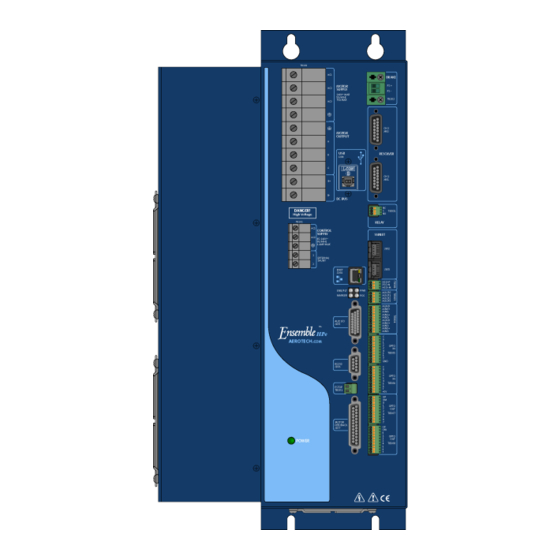
- Page 1 Ensemble HPe 150/200 Hardware Manual P/N: EDU198 Revision: 4.06.00...
- Page 2 This manual contains proprietary information and may not be reproduced, disclosed, or used in whole or in part without the express written permission of Aerotech, Inc. Product names mentioned herein are used for identification purposes only and may be trademarks of their respective companies.
-
Page 3: Table Of Contents
Table of Contents Ensemble HPe 150/200 Table of Contents Table of Contents List of Figures List of Tables EC Declaration of Conformity Agency Approvals Safety Procedures and Warnings Quick Installation Guide xiii Chapter 1: Introduction 1.1. Drive and Software Compatibility 1.2. - Page 4 Ensemble HPe 150/200 Table of Contents 2.6. Brake Power Supply (TB202) 2.6.1. Solid State Relay Specifications (TB202) 2.7. Aeronet Interface (J209/J210) 2.8. RS-232 Interface (J206) 2.9. -EXTSHUNT Option (TB101) 2.10. PC Configuration and Operation Information Chapter 3: -I/O Expansion Board 3.1.
-
Page 5: Table Of Contents
Table of Contents Ensemble HPe 150/200 List of Figures Figure 1-1: Ensemble HPe 150/200 Networked Digital Drive Figure 1-2: Functional Diagram Figure 1-3: Dimensions Figure 2-1: Control Supply Connections Figure 2-2: Motor Bus Input Connections Figure 2-3: Brushless Motor Configuration Figure 2-4:... -
Page 6: Table Of Contents
Ensemble HPe 150/200 Table of Contents Figure 3-10: Analog Output 1 Connector (TB303) Figure 3-11: Analog Input Typical Connection (TB304) Figure 3-12: Opto-Isolated Inputs Figure 3-13: Inputs Connected to a Current Sourcing Device Figure 3-14: Inputs Connected to a Current Sinking Device Figure 3-15: Opto-Isolated Outputs (-IO Board) -
Page 7: List Of Tables
Table 2-2: Motor Supply Input Wiring Table 2-3: Motor Power Output Connections Table 2-4: Wire Colors for Aerotech Supplied Cables (Brushless) Table 2-5: Wire Colors for Aerotech Supplied Cables (DC Brush) Table 2-6: Wire Colors for Aerotech Supplied Cables (Stepper) Table 2-7:... - Page 8 Ensemble HPe 150/200 Table of Contents Table 3-7: Brake / Mechanical Relay Connector Pin Assignment (J207) Table 3-8: PSO Output Interface Connector Pin Assignment (TB302) Table 3-9: PSO Output Mating Connector Table 3-10: PSO Output Polarity Settings for JP2 Table 3-11: Output Specifications ...
-
Page 9: Ec Declaration Of Conformity
Declaration of Conformity Ensemble HPe 150/200 EC Declaration of Conformity Manufacturer Aerotech, Inc. Address 101 Zeta Drive Pittsburgh, PA 15238-2897 Product Ensemble HPe 150/200 Model/Types This is to certify that the aforementioned product is in accordance with the applicable requirements of the... -
Page 10: Agency Approvals
Ensemble HPe 150/200 Declaration of Conformity Agency Approvals Aerotech, Inc. Model Ensemble HPe 150/200 Series Digital Drives have been tested and found to be in accordance to the following listed Agency Approvals: Approval / Certification: CUS NRTL Approving Agency: TUV SUD America Inc. -
Page 11: Safety Procedures And Warnings
7. Make sure the Ensemble HPe 150/200 and all components are properly grounded in accordance with local electrical safety requirements. 8. Operator safeguarding requirements must be addressed during final integration of the product. D A N G E R : The Ensemble HPe 150/200 case temperature may exceed 75°C in some applications. www.aerotech.com... - Page 12 Exceeding environmental or operating specifications can cause damage to the equipment. 5. If the Ensemble HPe 150/200 is used in a manner not specified by the manufacturer, the protection provided by the Ensemble HPe 150/200 can be impaired and result in damage, shock, injury, or death.
-
Page 13: Quick Installation Guide
This chapter describes the order in which connections and settings should typically be made to the Ensemble HPe 150/200. If a custom interconnection drawing was created for your system (look for a line item on your Sales Order under the heading “Integration”), that drawing can be found on your software DVD. - Page 14 Ensemble HPe 150/200 Quick Installation Guide This page intentionally left blank. www.aerotech.com...
-
Page 15: Chapter 1: Introduction
Aerotech’s Ensemble HPe 150/200 (High Power PWM) network digital drive is a high performance amplifier.The drive provides deterministic behavior, auto-identification, and easy software setup. The Ensemble HPe 150/200’s high performance double precision floating point DSP controls the digital PID and current loops. All system configuration is done using software-settable parameters, including control loop gains and system safety functions. -
Page 16: Table 1-1: Feature Summary
Ensemble HPe 150/200 Introduction Table 1-1: Feature Summary Standard Features Line driver square wave quadrature encoder input for position and velocity feedback Line driver square wave auxiliary quadrature encoder input or output for PSO Four opto-isolated user outputs Six opto-isolated user inputs (two high speed) One 16-bit differential analog input (± 10 V) -
Page 17: Table 1-2: Accessories
24 VDC, 1 A power supply for optional brake/relay output BRAKE24-2 24 VDC, 2 A power supply for optional brake Cables Interconnection A complete list of Aerotech cables can be found on the website at http://www.aerotechmotioncontrol.com/manuals/index.aspx Joystick/Handwheel Refer to Section 5.1. Section 5.2. -
Page 18: Figure
Ensemble HPe 150/200 Introduction The following block diagram shows a connection summary. For detailed connection information, refer to Chapter 2 and Chapter 3. Aeronet Input (J209) -IO Option J209/J210 AERONET Aeronet Output (J210) Relay TB301 (jumper configurable) RELAY J208 USB 2.0 Port... -
Page 19: Drive And Software Compatibility
Introduction Ensemble HPe 150/200 1.1. Drive and Software Compatibility The following table lists the available Ensemble drives and which version of the Ensemble software first provided support for a given drive. Drives that list a specific version number in the Last Software Version column will not be supported after the listed version. -
Page 20: Electrical Specifications
Ensemble HPe 150/200 Introduction 1.2. Electrical Specifications Table 1-4: Electrical Specifications Description HPe 150 HPe 200 Input Voltage 14-240 VAC Input Frequency 50-60 Hz Motor Maximum Continuous Input Supply 43.30 A 57.74 A Current Input Current Refer to Section 1.2.1. System Power Requirements... -
Page 21: System Power Requirements
Introduction Ensemble HPe 150/200 1.2.1. System Power Requirements The following equations can be used to determine total system power requirements. The actual power required from the mains supply will be the combination of actual motor power (work), motor resistance losses, and efficiency losses in the power electronics or power transformer. An EfficiencyFactor of approximately 90% should be used in the following equations. -
Page 22: Mechanical Design
Ensemble HPe 150/200 Introduction 1.3. Mechanical Design Install the unit into a construction compliant for unlimited circuits enclosure. Each unit should be separated from other drives and surrounded by 25 mm (1") of free air space. A space of 100 mm (4") should be allowed along the front of the unit for cable connections. -
Page 23: Table 1-5: Physical Specifications
Introduction Ensemble HPe 150/200 Table 1-5: Physical Specifications Weight Standard 11.06 kg (24.4 lb) w/ -IO option 11.46 kg (25.28 lb) w/ -RDP option 11.46 kg (25.28 lb) Table 1-6: Heat Sink Specifications Typical Size 167.9 mm x 90.1 mm x 393.8 mm (6.61 in x 3.55 in x 15.5 in) Maximum Temperature 65 °C... -
Page 24: Environmental Specifications
Ensemble HPe 150/200 Introduction 1.4. Environmental Specifications The environmental specifications for the Ensemble HPe 150/200 are listed below. Ambient Temperature Operating: 0° to 50°C (32° to 122° F) Storage: -30° to 85°C (-22° to 185° F) Humidity Maximum relative humidity is 80% for temperatures up to 31°C. -
Page 25: Chapter 2: Installation And Configuration
Installation and Configuration Ensemble HPe 150/200 Chapter 2: Installation and Configuration This chapter describes the switches, jumpers, and connections when used with a DC brush, brushless, or stepper motor. www.aerotech.com Chapter 2... -
Page 26: Power Connections
Ensemble HPe 150/200 Installation and Configuration 2.1. Power Connections The Ensemble HPe 150/200 has two AC input connectors; one for control power and a second for motor power. For a complete list of electrical specifications, refer to Section 1.2. N O T E : The machine integrator, OEM or end user is responsible for meeting the final protective ground- ing requirements of the system. -
Page 27: Control Supply Connections
The control power supply input allows the Ensemble HPe 150/200 to maintain communications if the motor power is removed, such as in an Emergency Stop condition. The control power supply requires a minimum of 85 VAC input to operate properly. -
Page 28: Motor Supply Connections
Power for the cooling fan is supplied through the motor supply connection. The fan connects between the AC1 and AC2 inputs and uses approximately 20W of power. W A R N I N G : Do not operate the Ensemble HPe 150/200 without the safety ground connection in place. -
Page 29: Minimizing Conducted, Radiated, And System Noise
The shield of the cables must be connected to the metal back shell in order for the product to conform to the radiated emission standards. The Ensemble HPe 150/200 is a component designed to be integrated with other electronics. EMC testing must be conducted on the final product configuration. -
Page 30: Motor Output Connections
Ensemble HPe 150/200 Installation and Configuration 2.2. Motor Output Connections The Ensemble HPe 150/200 is capable of controlling three motor types: Brushless (see Section 2.2.1.) DC Brush (see Section 2.2.2.) Stepper (see Section 2.2.3.) For a complete list of electrical specifications, refer to Section 1.2. -
Page 31: Brushless Motor Connections
Both methods will identify the A, B, and C Hall/motor lead sets and indicate the correct connections to the drive. N O T E : If using standard Aerotech motors and cables, motor and encoder connection adjustments are not required. -
Page 32: Powered Motor Phasing
Ensemble HPe 150/200 Installation and Configuration 2.2.1.1. Powered Motor Phasing To test the initial set of motor connections, run the MotorVerification.ab test program. The program will attempt to move the motor forward in a positive (CW) direction. Depending on the information that the program gathers during the test, you may be prompted to rearrange motor lead connections and run the test again. -
Page 33: Figure
Installation and Configuration Ensemble HPe 150/200 Figure 2-4: Encoder and Hall Signal Diagnostics www.aerotech.com Chapter 2... -
Page 34: Unpowered Motor And Feedback Phasing
1. Aerotech phasing configuration expects ØC to be the lead signal (in time), ØB to follow it, and ØA to follow ØB. This means that whichever signal has its sine wave peak farthest to the left should be designated as the ØC signal. -
Page 35: Figure
After the motor leads have been tested, the next step is to determine the phase of the Hall signals. The required (by an Aerotech system) relationship between motor and Hall leads is that the peak of a motor lead signal should correspond to the low voltage phase of the Hall signal (as shown in Figure 2-6). -
Page 36: Brushless Motor Phasing Goal
With the designations of the motor and Hall leads of a third party motor determined, the motor can now be connected to an Aerotech system. Connect motor lead A to motor connector A, motor lead B to motor connector B, and motor lead C to motor connector C. Connect Hall lead A to Pin 10 of the feedback connector. -
Page 37: Dc Brush Motor Connections
Red & Orange Yellow & Blue Black Yellow & Blue (1) Wire Color Set #1 is the typical Aerotech wire set used by Aerotech. (2) “&” (Red & Orange) indicates two wires; “ / ” (Green/White) indicates a single wire www.aerotech.com Chapter 2... -
Page 38: Dc Brush Motor Phasing
When the voltmeter indicates a positive value, the motor leads have been identified. 5. Connect the motor lead from the voltmeter to the ØA motor terminal on the Ensemble HPe 150/200. Connect the motor lead from the negative lead of the voltmeter to the ØC motor terminal on the Ensemble HPe 150/200. -
Page 39: Stepper Motor Connections
Green/Yellow & Shield Black Brown Yellow White White & Red (1) Wire Color Set #1 is the typical Aerotech wire set used by Aerotech. (2) “&” (Red & Orange) indicates two wires; “ / ” (Green/White) indicates a single wire www.aerotech.com Chapter 2... -
Page 40: Stepper Motor Phasing
POSITIVE MOTION Figure 2-11: Clockwise Motor Rotation N O T E : If using standard Aerotech motors and cables, motor and encoder connection adjustments are not required. N O T E : After the motor has been phased, use the ReverseMotionDirection parameter to change the dir- ection of “positive”... -
Page 41: Motor Feedback Connections (J207)
Installation and Configuration Ensemble HPe 150/200 2.3. Motor Feedback Connections (J207) The motor feedback connector (a 25-pin, D-style connector) has inputs for an encoder, limit switches, Hall- effect devices, motor over-temperature device, 5 Volt encoder and limit power, and optional brake connection. -
Page 42: Encoder Interface (J207)
Motor Feedback (J207) connector. The standard encoder interface will accept an RS-422 differential line driver signal. If the Ensemble HPe 150/200 has been purchased with the -MXH option, the standard encoder interface can optionally be configured for an analog encoder input via parameter settings. -
Page 43: Line Driver Encoder (Standard)
Installation and Configuration Ensemble HPe 150/200 2.3.1.1. RS-422 Line Driver Encoder (Standard) The standard encoder interface accepts an RS-422 differential quadrature line driver signal in the range of 0 to 5 Volts. It accepts a 10 MHz (max) encoder signal frequency (25 nsec minimum edge separation), producing 40 million counts per second after times four (x4) quadrature decoding. -
Page 44: Endat Encoder Interface (J207)
Ensemble HPe 150/200 Installation and Configuration 2.3.1.2. EnDat Encoder Interface (J207) The Ensemble HPe 150/200 retrieves absolute position data along with encoder fault information via a serial data stream from the absolute encoder. See Figure 2-13 for the serial data stream interface. Set up of this... -
Page 45: Resolute Encoder Interface (J207)
Installation and Configuration Ensemble HPe 150/200 2.3.1.3. Resolute Encoder Interface (J207) The Ensemble HPe 150/200 retrieves absolute position data along with encoder fault information via a serial data stream from the resolute encoder. See Figure 2-14 for the serial data stream interface. Set up of this interface requires setting parameters ResoluteEncoderResolution, ResoluteEncoderSetup, and ResoluteEncoderUserResolution. -
Page 46: Analog Encoder Interface
Ensemble HPe 150/200 Installation and Configuration 2.3.1.4. Analog Encoder Interface If the -MXH option has been purchased, the standard encoder channel will accept an analog encoder input signal. The multiplication (interpolation) factor is determined by the EncoderMultiplicationFactor parameter. Table 2-9:... -
Page 47: Analog Encoder Interface (J207)
Installation and Configuration Ensemble HPe 150/200 J207-17 SIN+ 82PF 82PF J207-18 SIN- AD822 82PF 82PF J207-14 COS+ 82PF 82PF J207-15 COS- AD822 82PF 82PF MRK+ J207-7 82PF 82PF MRK- J207-6 AD822 82PF 82PF Figure 2-16: Analog Encoder Interface (J207) www.aerotech.com... -
Page 48: Encoder Phasing
Ensemble HPe 150/200 Installation and Configuration 2.3.1.5. Encoder Phasing Incorrect encoder polarity will cause the system to fault when enabled or when a move command is issued. Figure 2-17 illustrates the proper encoder phasing for clockwise motor rotation (or positive forcer movement for linear motors). -
Page 49: Position Feedback In The Diagnostic Display
Installation and Configuration Ensemble HPe 150/200 Figure 2-18: Position Feedback in the Diagnostic Display www.aerotech.com Chapter 2... -
Page 50: Hall-Effect Interface (J207)
Ensemble HPe 150/200 Installation and Configuration 2.3.2. Hall-Effect Interface (J207) The Hall-effect switch inputs are recommended for AC brushless motor commutation but not absolutely required. The Hall-effect inputs accept 5-24 VDC level signals. Refer to Section 2.2.1.1. for Hall-effect device phasing. -
Page 51: Thermistor Interface (J207)
Installation and Configuration Ensemble HPe 150/200 2.3.3. Thermistor Interface (J207) The thermistor input is used to detect an over temperature condition in a motor using a positive temperature coefficient sensor. As the temperature of the sensor increases, so does the resistance. Under normal operating conditions, the resistance of the thermistor is low (i.e., 100 ohms) which will result in a low input... -
Page 52: Encoder Fault Interface (J207)
Ensemble HPe 150/200 Installation and Configuration 2.3.4. Encoder Fault Interface (J207) The encoder fault input is used with encoders having a fault output. Each manufacturer uses this signal to indicate different faults. Table 2-12: Encoder Fault Interface Pin Assignment (J207) -
Page 53: End Of Travel Limit Input Interface (J207)
Installation and Configuration Ensemble HPe 150/200 2.3.5. End Of Travel Limit Input Interface (J207) End of Travel (EOT) limits are required to define the end of the physical travel on linear axes. Positive or clockwise motion is stopped by the clockwise (CW) end of travel limit input. Negative or counterclockwise motion is stopped by the counterclockwise (CCW) end of travel limit input. -
Page 54: End Of Travel Limit Interface Input (J207)
Ensemble HPe 150/200 Installation and Configuration +3.3V 74AC16244 CW/+LMT J207-12 CCW/-LMT J207-24 HMLMT J207-22 Figure 2-23: End of Travel Limit Interface Input (J207) Chapter 2 www.aerotech.com... -
Page 55: End Of Travel Limit Phasing
Installation and Configuration Ensemble HPe 150/200 2.3.5.1. End Of Travel Limit Phasing If the EOT limits are reversed, you will be able to move further into a limit but be unable to move out. To correct this, swap the connections to the CW and CCW inputs at the J207 connector. The logic level of the EOT limit inputs may be viewed in the diagnostic display (shown in... -
Page 56: Brake Output (J207)
(refer to the Ensemble Help file for more information). Use either the solid state relay on the Ensemble HPe 150/200 or the mechanical relay on the -IO board when connecting a power supply to the brake outputs on J207. Do not use both relays at the same time. -
Page 57: Emergency Stop Sense Input (Tb201)
Installation and Configuration Ensemble HPe 150/200 2.4. Emergency Stop Sense Input (TB201) The ESTOP sense input (TB201) is used to monitor the state of an external safety circuit only. This state is indicated by the software and may be used to facilitate system restart. This ESTOP sense input is not intended to be a complete safety system. -
Page 58: Typical Estop Interface
This will remove power to the motor while maintaining control power, as shown in the Figure 2- The external relay must be sized based on the number of the Ensemble HPe 150/200s connected and the peak current rating of each drive. -
Page 59: Auxiliary I/O Connector (J205)
Installation and Configuration Ensemble HPe 150/200 2.5. Auxiliary I/O Connector (J205) The Auxiliary I/O connector (J205) provides 1 analog and 6 digital inputs, 1 analog and 4 digital outputs, and a secondary RS-422 line driver encoder input. Table 2-19: Auxiliary I/O Connector Pin Assignment (J205) -
Page 60: Auxiliary Encoder Channel (J205)
Ensemble HPe 150/200 Installation and Configuration 2.5.1. Auxiliary Encoder Channel (J205) The auxiliary encoder interface accepts a 5 VDC RS-422 differential quadrature line driver signal. It accepts a 10 MHz (max) encoder signal frequency (25 nsec minimum edge separation), producing 40 million counts per second, after times four (x4) quadrature decoding. -
Page 61: Auxiliary Encoder Channel (J205)
Installation and Configuration Ensemble HPe 150/200 AUX SIN- IN J205-2 AUX SIN+ IN J205-1 ADM1485 AUX COS- IN J205-11 AUX COS+ IN J205-10 ADM1485 AUX MRK- IN J205-19 AUX MRK+ IN J205-20 ADM1485 Figure 2-27: Auxiliary Encoder Channel (J205) www.aerotech.com... -
Page 62: Position Synchronized Output (Pso)/Laser Firing (J205)
Installation and Configuration 2.5.2. Position Synchronized Output (PSO)/Laser Firing (J205) The Ensemble HPe 150/200 includes a Position Synchronized Output (PSO) feature. The PSO output is available on the dual function AUXMRK± differential signal lines (use of an RS-422 line receiver or opto- isolator is recommended). -
Page 63: Pso Interface
Installation and Configuration Ensemble HPe 150/200 Differential +5 VDC 120 - 180 (typical) J205 Active Low Aux. Marker Output * Opto-Isolated +5 VDC Isolated Section J205 10 mA 180 Aux. Marker To Laser Active Low 1N4148 Output* HCPL-2601 or 6N136 * Active low output shown. -
Page 64: Opto-Isolated Outputs 0-3 (J205)
Ensemble HPe 150/200 Installation and Configuration 2.5.3. Opto-Isolated Outputs 0-3 (J205) All outputs are rated for 24 VDC and 80 mA per output. The outputs are software configurable as current sinking (see Figure 2-29) or current sourcing (see Figure 2-30) . -
Page 65: Outputs Connected In Current Sinking Mode (J205)
Installation and Configuration Ensemble HPe 150/200 J205 LOAD 5-24 VDC OUTPUT SWITCHES OPTOOUT0 J205-7 LOAD OPTOOUT1 J205-8 LOAD OPTOOUT2 J205-9 LOAD OPTOOUT3 J205-16 OPTOCOM J205-15 EACH OUTPUT 80 mA MAXIMUM DIODE REQUIRED ON EACH OUTPUT THAT DRIVES AN INDUCTIVE DEVICE (COIL), SUCH AS A RELAY. -
Page 66: Opto-Isolated Inputs 0-3 (J205)
Ensemble HPe 150/200 Installation and Configuration 2.5.4. Opto-Isolated Inputs 0-3 (J205) User inputs 0-3 are scaled for an input voltage of 5-24 VDC. Figure 2-31 Figure 2-32, respectively, illustrate how to connect a device in current sinking and sourcing current modes. -
Page 67: Inputs Connected In Current Sinking Mode (J205)
Installation and Configuration Ensemble HPe 150/200 J205 OPTOINCOM J205-24 OPTOIN0 J205-17 5-24VDC OPTOIN1 J205-18 OPTOIN2 J205-25 OPTOIN3 J205-26 INPUT SWITCHES Figure 2-31: Inputs Connected in Current Sinking Mode (J205) J205 INPUT SWITCHES OPTOIN0 J205-17 OPTOIN1 J205-18 OPTOIN2 J205-25 5-24VDC OPTOIN3... -
Page 68: High Speed User Inputs 4-5 (J205)
Ensemble HPe 150/200 Installation and Configuration 2.5.5. High Speed User Inputs 4-5 (J205) The high-speed inputs are scaled for 5 V or 24 V input voltages based on a jumper setting (Table 2-28). A higher input voltage requires adding external series resistors to limit the current to 10 mA. The high-speed inputs are isolated by an HCPL-0630 and have a typical delay of 50 nanoseconds. -
Page 69: Analog Output 0 (J205)
Installation and Configuration Ensemble HPe 150/200 2.5.6. Analog Output 0 (J205) Analog Output 0 produces a single ended output in the range of ±10 volts with a resolution of 305 µV (16-bit). The maximum recommended output current is 5 mA (2 k Ohm load). The analog output voltage is referenced to J205-23. -
Page 70: Analog Input 0 (J205)
Ensemble HPe 150/200 Installation and Configuration 2.5.7. Analog Input 0 (J205) Analog Input 0 is a 16-bit differential input that accepts a voltage in the range of ±10 V with a resolution of 305 µV. Signals outside of this range may damage the input. To interface to a single-ended (non-differential) voltage source, connect the signal common of the source to the negative input (pin 14, ANALOG_IN-) and the analog source signal to the positive input (pin 13, ANALOG_IN+). -
Page 71: Brake Power Supply (Tb202)
Installation and Configuration Ensemble HPe 150/200 2.6. Brake Power Supply (TB202) TB202 is the power supply connection to the onboard solid state brake control relay. The relay is typically used to automatically control a fail-safe brake on a vertical axis. It can also be used as a general purpose output. -
Page 72: Brake Connected To J207
Ensemble HPe 150/200 Installation and Configuration Figure 2-36 is an example of a +24 VDC Brake connected to J207, the Motor Feedback connector. In this example the external +24 VDC power source is connected to TB202. DRIVE BRAKE PS+ TB202-1... -
Page 73: Brake Connected To Tb202
Installation and Configuration Ensemble HPe 150/200 Figure 2-37 is an example of a 24 VDC Brake connected to TB202. The user must connect J207 pin 13 to J207 pin 25. In this case, J207 would function as an interlock to prevent the brake from releasing if the Motor Feedback connector is not connected. -
Page 74: Solid State Relay Specifications (Tb202)
The user must verify that the brake power requirements are within the specifications of the Brake control relay listed below. Table 2-34: Relay Specifications Solid State Relay Rating (M173 / PS710E-1A), Aerotech PN: ECS1079 Maximum Voltage 24 VDC Maximum Current 0.5 Amps... -
Page 75: Aeronet Interface (J209/J210)
PC to any of the secondary units will result in a connection failure. Any discrete unit is capable of acting as the primary Ensemble HPe 150/200. The unit acting as the primary is dictated by the connection of the Aeronet. A primary drive will only act as an output. A secondary drive (in a configuration with three or more drives) will act as an input and output. -
Page 76: Interface (J206)
Ensemble HPe 150/200 Installation and Configuration 2.8. RS-232 Interface (J206) Connecting the RS-232 port to a user’s PC requires a standard cable (not a null modem). Table 2-36: RS-232 Connector Pin Assignment (J206) Pin# Description In/Out/Bi Connector +5 Volt Power Output... -
Page 77: Extshunt Option (Tb101)
The Ensemble HPe 150/200 provides an external shunt option for high-energy systems. Internally, the shunt is fused with an 8A slow-blow type fuse. The purpose of the fuse is to protect the electronic switching device and the traces on the circuit board. -
Page 78: Table 2-39: Maximum Storage Energy
= turn on voltage for shunt circuit (V) (=380 V) = nominal Bus voltage (V) (160 V or 320 V Typical) For a standard Ensemble HPe 150/200, the maximum energy the internal bus capacitor can store without requiring a shunt resistor is indicated in Table 2-39. - Page 79 Installation and Configuration Ensemble HPe 150/200 Equation 5: − − (Watts) CYCLE = time between decelerations + time to deceleration (seconds) CYCLE = hysteresis point of regeneration circuit (=10 V) Additional useful equations: 1 lb-ft = 1.356 Nm ω (Useful as an estimate if the deceleration time is unknown) ω...
-
Page 80: Pc Configuration And Operation Information
Ensemble HPe 150/200 Installation and Configuration 2.10. PC Configuration and Operation Information For additional information about Ensemble HPe 150/200 and PC configuration, hardware requirements, programming, utilities and system operation refer to the Ensemble Help file. Chapter 2 www.aerotech.com... -
Page 81: Chapter 3: -I/O Expansion Board
ECK01294 ECK01294 ECK01294 TB302 TB303 TB304 Figure 3-1: Ensemble HPe 150/200 with -IO Option Board Table 3-1: -IO Expansion Board Jumper Configuration Jumper Setting Description PSO Output Active High, Low Z during reset PSO Output Active Low, High Z during reset... -
Page 82: Brake / Mechanical Relay (Tb301)
Ensemble HPe 150/200 -IO Expansion Board 3.1. Brake / Mechanical Relay (TB301) The relay output is typically used for automatic control of a fail-safe brake on a vertical axis. It can also be used as a general purpose relay. The brake output can be software configured; refer to the Ensemble Help file for more information (see topics for the EnableBrakeControl parameter and the BRAKE command). -
Page 83: Brake / Mechanical Relay Interface Connector
-IO Expansion Board Ensemble HPe 150/200 3.1.3. Brake / Mechanical Relay Interface Connector The normally-open relay contacts are accessible through TB301 and the Motor Feedback connector (J207). The normally-closed relay contact is only accessible through TB301 (see Figure 3-3). The Motor Feedback connector allows the brake wires to be included in the motor feedback cable and eliminate the need for a separate brake cable. -
Page 84: Brake Connected To Tb301
Ensemble HPe 150/200 -IO Expansion Board N O T E : The user is responsible for providing fuse protection for the brake circuit. Figure 3-3 is an example of a +24 VDC Brake connected to TB301. In this example, JP3 must be set 1-3 and all other jumpers removed. -
Page 85: Pso Output Interface (Tb302)
1881338 0.5 - 0.080 [20-28] N O T E : If your Ensemble HPe 150/200 was purchased after July 2013, refer to Section 3.2.1. N O T E : If your Ensemble HPe 150/200 was purchased before July 2013, refer to Section 3.2.3. -
Page 86: Pso Opto Output
JP2 is installed in the 1-2 position giving normally-closed operation. This mode should be used with caution since the Ensemble HPe 150/200 cannot maintain the closed state when its AC mains power is turned off. The PSO-NC (JP2 1-2 setting) should not be used when fail-safe operation is required. JP2 jumper settings... -
Page 87: Dualpso And -Triplepso Laser Firing Options
Figure 3-6) from J302 to J302 of each HPe (J302 to J302 or J303 to J303 of the other Ensemble HPe 150/200, both connectors have two bi- directional ports). Refer to the Ensemble Help File for programming information. Multi-axis PSO can track encoder signals with a maximum data rate of 8.33 MHz. Signals in excess of this rate will cause a loss of PSO accuracy. Software controlled PSO pre-scalars may be used to limit the data... -
Page 88: Two/Three Axis Laser Firing Interconnection
Ensemble HPe 150/200 -IO Expansion Board Z Axis Y Axis X Axis SSI 1 SSI 2 SSI 1 SSI 2 SSI 1 SSI 2 Input Primary Encoder Input Input Primary Encoder Input J302 J303 J302 J303 J302 J303 NOTES: Z axis is routing its primary encoder data to X axis (as well as Y axis) through SSI port 1. -
Page 89: Pso Opto Output (Archive)
-IO Expansion Board Ensemble HPe 150/200 3.2.3. PSO Opto Output (Archive) N O T E : If your Ensemble HPe 150/200 was purchased after July 2013, refer to Section 3.2.1. The PSO Opto Output is shown in Figure 3-7 Figure 3-8. -
Page 90: Pso Opto-Chip Installation
Ensemble HPe 150/200 -IO Expansion Board 8-PIN OPTO CHIP (Sink Only) 6-PIN OPTO CHIP (Sink or Source) NOTE: When installing the 6-pin opto-chip, Pin 1 on the chip matches to Pin 2 on the socket (Pin 1 and Pin 8 on the socket should be free). -
Page 91: Analog Outputs (Tb303)
-IO Expansion Board Ensemble HPe 150/200 3.3. Analog Outputs (TB303) The three 16-bit analog outputs produce a single-ended output voltage in the range of ±10 V with a resolution of 305 µV. The maximum recommended output current is 5 mA. Analog outputs are referenced to TB304-1. -
Page 92: Analog Inputs (Tb304)
Ensemble HPe 150/200 -IO Expansion Board 3.4. Analog Inputs (TB304) The three I/O board analog inputs are16-bit differential inputs that accept a voltage in the range of ±10 volts with a resolution of 305 µV. Signals outside of this range may damage the input. To interface to a single- ended (non-differential) voltage source, connect the signal common of the source to the negative input, and the analog source signal to the positive input. -
Page 93: User Power (Tb305, Tb306)
-IO Expansion Board Ensemble HPe 150/200 3.5. User Power (TB305, TB306) A user accessible power supply (+5V at 0.5 A) is available between the TB306 +5V terminal and TB305 GND terminal. Table 3-18: User Common Connector Pin Assignment (TB305) Pin#... -
Page 94: Opto-Isolated Inputs (Tb305, Tb306)
Ensemble HPe 150/200 -IO Expansion Board 3.6. Opto-Isolated Inputs (TB305, TB306) These opto-isolated inputs use a PS2806-4 device and are configured for 5-24 volt input levels. The inputs may be connected to current sourcing or current sinking devices, as shown in... - Page 95 -IO Expansion Board Ensemble HPe 150/200 W A R N I N G : Opto-isolated inputs and outputs should not be powered by the user output power. Doing so would compromise the isolation provided by the opto-isolator. N O T E : Each bank of 8 Inputs must be connected in the all sourcing or all sinking configuration.
- Page 96 Ensemble HPe 150/200 -IO Expansion Board TB306 INPUT SWITCH DEVICES TB306-2 TB306-3 5-24 VDC TB306-4 TB306-5 TB306-1 Applies to -IO and -IOH boards Figure 3-13: Inputs Connected to a Current Sourcing Device TB306 TB306-1 TB306-2 5-24VDC TB306-3 TB306-4 TB306-5 INPUT SWITCH DEVICES...
-
Page 97: Opto-Isolated Outputs (Tb307, Tb308)
-IO Expansion Board Ensemble HPe 150/200 3.7. Opto-Isolated Outputs (TB307, TB308) The outputs are software configurable as sourcing or sinking. The outputs are driven by PS2802-4 opto- isolators rated for 24 volts maximum and up to 80 mA/output @ 20°C. - Page 98 Ensemble HPe 150/200 -IO Expansion Board TB308-3 TB308-4 TB308-5 TB308-6 PS2802-4 TB308-2 PS2802-4 10UF 50V TB308-1 TB308-10 TB308-9 TB308-8 PS2802-4 Applies to the -IO board PS2802-4 Figure 3-15: Opto-Isolated Outputs (-IO Board) Chapter 3 www.aerotech.com...
-
Page 99: Table 3-27: Output Specifications (Tb307, Tb308)
-IO Expansion Board Ensemble HPe 150/200 Table 3-27: Output Specifications (TB307, TB308) PS2802-4 Opto Device Specifications Value Maximum Voltage 24 V maximum Maximum Sink/Source Current 80 mA/channel @ 20°C; 60 mA/channel @ 50°C Output Saturation Voltage 2.75 V at maximum current Output Resistance 33 Ω... - Page 100 Ensemble HPe 150/200 -IO Expansion Board TB308 TB308-1 OUTPUT SWITCHES LOAD 5-24 VDC TB308-6 LOAD TB308-5 LOAD TB308-4 LOAD TB308-3 TB308-2 CONNECTION REQUIRED EACH OUTPUT 80 mA MAXIMUM DIODE REQUIRED ON EACH OUTPUT THAT DRIVES AN INDUCTIVE DEVICE (COIL), SUCH AS A RELAY.
-
Page 101: Ssinet (J302/J303)
SSINet interface if used. Each of these two SSINet interfaces are both available on the J302 and J303 connectors, as illustrated in the following table. The SSINet is designed for daisy-chaining encoder signals from one Ensemble HPe 150/200 to another for two/three-axis PSO (laser firing). This allows one Ensemble HPe 150/200 containing the -DUALPSO or - TRIPLEPSO options to track the vectorial position change of two/three axes in real-time. - Page 102 Ensemble HPe 150/200 -IO Expansion Board RS422-1M J302-1 RS422-1P J302-2 ADM1485 RS422-2M J302-7 RS422-2P J302-8 ADM1485 RS422-3M J302-4 RS422-3P J302-5 ADM1485 RS422-4M J302-3 RS422-4P J302-6 ADM1485 Applies to the -IO and -IOH boards Figure 3-18: J302/J303 Chapter 3 www.aerotech.com...
-
Page 103: Chapter 4: -Rdp Expansion Board
-RDP Expansion Board Ensemble HPe 150/200 Chapter 4: -RDP Expansion Board The resolver to digital option (-RDP) provides up to two industry standard resolver or inductosyn channels that can be used as a feedback device. The standard reference frequency output is 5 kHz, with factory options for either 7.5 kHz or 10.0 kHz. -
Page 104: Table 4-2: -Rdp Connector Pin Assignment (J401/J402)
Ensemble HPe 150/200 -RDP Expansion Board Table 4-2: -RDP Connector Pin Assignment (J401/J402) Pin# Label Description In/Out/Bi Shell Shield Connecter shell for cable shield termination Input SIN+ Resolver Sine + Input SIN- Resolver Sine - Input Shield Resolver Sine Shield... - Page 105 -RDP Expansion Board Ensemble HPe 150/200 PRE-AMP RESOLVER TO RESOLVER/ (INDUCTOSYN ONLY) DIGITAL CONVERTER INDUCTOSYN SIN+ SIN- SHIELD N.C. COS+ COS- SHIELD N.C. OPTIONAL REF+ REF- SHIELD N.C. Individually shielded twisted-pair cables are recommended. Figure 4-2: Resolver/Inductosyn Recommended Wiring +12V...
-
Page 106: Table 4-4: Resolver Test Points
Ensemble HPe 150/200 -RDP Expansion Board ENC MRK1- J401-12 ENC MRK1+ 26LS31 J401-2 ENC SIN1- J401-11 ENC SIN1+ J401-7 26LS31 ENC COS1- J401-6 ENC COS1+ 26LS31 J401-1 Figure 4-4: Encoder Emulation Outputs The external power connector (J403) is a factory-select configuration and is not available on all drives. -
Page 107: Chapter 5: Standard Interconnection Cables
Accessories Ensemble HPe 150/200 Chapter 5: Standard Interconnection Cables N O T E : A complete list of Aerotech cables can be found on the website at http://www.aerotechmotioncontrol.com/manuals/index.aspx. Table 4-1: Standard Interconnection Cables Cable Part # Description Joystick Section 5.1. -
Page 108: Joystick Interface
Accessories 5.1. Joystick Interface Aerotech joysticks JI (NEMA12 (IP54) rated) and JBV are powered from 5V and have a nominal 2.5V output in the center detent position. Two switches are used to select axis pairs and speed ranges. An optional interlock signal is used to indicate to the controller that the joystick is present. -
Page 109: Two Axis Joystick Interface (To The Aux I/O And I/O
Accessories Ensemble HPe 150/200 Second Axis to cable shield AGND JOY-Y Analog Input 1+ Common Analog Input 1- Joystick J205 First Axis JOY-X Analog Input 0+ Common Analog Input 0- +5 Volts AGND Common Input Common IN914 Button A Input 1... -
Page 110: Handwheel Interface
Accessories 5.2. Handwheel Interface A handwheel (such as the Aerotech HW-xxx-xx) can be used to manually control axis position. The handwheel must provide 5V differential quadrature signals to the Ensemble HPe 150/200. A handwheel can be connected to the Aux I/O as shown in... -
Page 111: Chapter 6: Maintenance
Maintenance Ensemble HPe 150/200 Chapter 6: Maintenance This section covers the internal boards, important board components, and how to clean the drive. Troubleshooting is covered in-depth in the Ensemble Help file. D A N G E R : Always disconnect the Mains power connection before opening the Ensemble HPe 150/200 chassis. -
Page 112: Power Board
Ensemble HPe 150/200 Maintenance 6.1. Power Board The figure below highlights the important components located on the power board. D A N G E R : Always disconnect the Mains power connection before opening the Ensemble HPe 150/200 chassis. GREEN... -
Page 113: Control Board
Maintenance Ensemble HPe 150/200 6.2. Control Board The figure below highlights the important components located on the control board. Mate: ECK01250 TB201 J207 J205 J204 J206 J203A J203A J203A Mate: ECK01250 TB202 J208 F.S. F.S. J209 J210 Board Assembly Drawing Number: 690D1635, Rev. -... -
Page 114: Table 5-4: Control Board Fuse Information
Ensemble HPe 150/200 Maintenance Table 5-4: Control Board Fuse Information Fuse Description Size Aerotech P/N Manufacturer's P/N Radial Lead Resettable Fuse 3 A EIF01001 Raychem RGE300 Surface Mount Fuse .05 A EIF01028 Raychem MICROSMD005F-2 Surface Mount Fuse .05 A EIF01028 Raychem MICROSMD005F-2 Surface Mount Fuse .05 A... -
Page 115: Preventative Maintenance
Cleaning The Ensemble HPe 150/200 chassis can be wiped with a clean, dry, soft cloth. The cloth may be slightly moistened if required with water or isopropyl alcohol to aid in cleaning if necessary. In this case, be careful not to allow moisture to enter the Ensemble HPe 150/200 or onto exposed connectors / components. - Page 116 Ensemble HPe 150/200 Maintenance This page intentionally left blank. Chapter 6 www.aerotech.com...
-
Page 117: Appendix A: Warranty And Field Service
Aerotech makes no warranty that its products are fit for the use or purpose to which they may be put by the buyer, whether or not such use or purpose has been disclosed to Aerotech in specifications or drawings previously or subsequently provided, or whether or not Aerotech’s... - Page 118 Aerotech's approval. On-site Warranty Repair If an Aerotech product cannot be made functional by telephone assistance or by sending and having the customer install replacement parts, and cannot be returned to the Aerotech service center for repair, and if Aerotech determines the problem could be warranty-related, then the following policy applies:...
-
Page 119: Appendix B: Revision History
Revision History Ensemble HPe 150/200 Appendix B: Revision History Revision Date Description 4.06.00 May 11, 2015 Added TUV certification information: Agency Approvals Added RoHS statement to Declaration of Conformity HPe 200 added Updated the Electrical Specifications (Input Power and related equation): Section 1.2. - Page 120 Ensemble HPe 150/200 Revision History Revision Date Description 4.01.00 September 03, 2009 Updated -IO and -IOH Opto-Isolated Inputs schematic 4.00.00 October 23, 2008 Full Revision / New Manual Appendix B www.aerotech.com...
-
Page 121: Index
Index Ensemble HPe 150/200 Index Analog Output 1 Connector Analog Output 1 Connector Pin Assignment -DUALPSO and -TRIPLEPSO Laser Firing Analog Outputs (I/O Board) Options Auxiliary Encoder Channel 46-47 -EXTSHUNT Option Auxiliary Encoder Channel Pin Assignment 46,48 -I/O Expansion Board... - Page 122 Ensemble HPe 150/200 Index Control Supply Connections End of Travel Limit Interface Input Control Supply specifications End Of Travel Limit Phasing EnDat Encoder Interface DC Brush Motor Connections Environmental Specifications DC Brush Motor Phasing ESTOP sense input Declaration of Conformity...
- Page 123 Index Ensemble HPe 150/200 Installation and Configuration Multi-axis PSO 48,73 Isolation optional joysticks J205 45-46,48,50-56 Options J206 Opto-Isolated Input Connector Pin Assignment J207 18,27-31,33,36-37,37-40,42,57-59,68-70 Opto-Isolated Inputs 52,80-81 J209 Opto-Isolated Output Connector Pin Assignment 83 J210 Opto-Isolated Outputs 50,83 J302 Opto-Isolated Outputs (-IO Board)
- Page 124 Ensemble HPe 150/200 Index PSO Output Interface Stepper Motor Connections PSO Output Interface Connector Pin Assignment 71 Stepper Motor Phasing PSO Output Polarity Settings for JP1 PSO Output Sources TB101 PWM Switching Frequency specifications TB201 TB202 57-60,68 Quick Installation Guide...
- Page 125 Index Ensemble HPe 150/200 Wire Colors for Supplied Cables 17,23,25 Wiring Control Supply www.aerotech.com...
- Page 126 Ensemble HPe 150/200 Index This page intentionally left blank. www.aerotech.com...
Need help?
Do you have a question about the HPe 150 and is the answer not in the manual?
Questions and answers