Sign In
Upload
Download
Table of Contents
Contents
Add to my manuals
Delete from my manuals
Share
URL of this page:
HTML Link:
Bookmark this page
Add
Manual will be automatically added to "My Manuals"
Print this page
×
Bookmark added
×
Added to my manuals
Manuals
Brands
Aerotech Manuals
Controller
ADRS Series
Hardware manual
Aerotech ADRS Series Hardware Manual
Hide thumbs
1
2
Table Of Contents
3
4
5
6
7
8
9
10
11
12
13
14
15
16
17
18
19
20
21
22
23
24
25
26
27
28
29
30
31
32
33
34
35
36
37
38
39
40
41
42
43
44
page
of
44
Go
/
44
Contents
Table of Contents
Troubleshooting
Bookmarks
Table of Contents
ADRS Hardware Manual
Table of Contents
List of Figures
List of Tables
Safety Procedures and Warnings
EU Declaration of Incorporation
Chapter 1: Overview
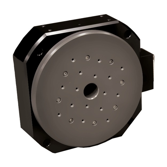
Figure 1-1: Typical ADRS Stage
Table 1-1: Model Options
Accuracy and Temperature Effects
Environmental Specifications
Table 1-2: Environmental Specifications
Basic Specifications
Table 1-3: ADRS Series Specifications
Chapter 2: Mechanical Specifications and Installation
Unpacking and Handling the Stage
Dimensions
Figure 2-1: ADRS100 Dimensions
Figure 2-2: ADRS150 Dimensions
Figure 2-3: ADRS200 Dimensions
Securing the Stage to the Mounting Surface
Table 2-1: Stage to Mounting Surface Hardware
Figure 2-4: ADRS Stage Standard Mounting Hole Locations
Attaching the Payload to the Stage
Figure 2-5: Load Orientations
Figure 2-6: ADRS Cantilevered Load Capabilities
Chapter 3: Electrical Specifications and Installation
Motor and Feedback Connectors
Table 3-1: 4-Pin Motor Connector Pinout
Table 3-2: 4-Pin Motor Connector Mating Connector
Table 3-3: 25-Pin Feedback Connector Pinout
Table 3-4: Feedback Connector Mating Connector
Motor and Feedback Wiring
Figure 3-1: Motor and Feedback Wiring
Motor and Feedback Specifications
Table 3-5: Feedback Specifications
Table 3-6: ADRS Series Resolution Information
Table 3-7: ADRS Series Maximum Encoder Frequency
Table 3-8: ADRS100 Motor Specifications [Aerotech Motor Model: S-76-35]
Table 3-9: ADRS150 Motor Specifications [Aerotech Motor Model: S-130-39]
Table 3-10: ADRS200 Motor Specifications [Aerotech Motor Model: S-180-44]
Marker and Machine Direction
Figure 3-2: Machine Direction
Motor and Feedback Phasing
Figure 3-3: Hall Phasing
Figure 3-4: Analog Encoder Phasing Reference Diagram
Figure 3-5: Encoder Phasing Reference Diagram (Standard)
Chapter 4: Maintenance
Service and Inspection Schedule
Cleaning and Lubrication
Rear Seal Change Procedure
Figure 4-1: Exploded View of Seal Assembly
Troubleshooting
Appendix A: Warranty and Field Service
Appendix B: Revision History
Index
Advertisement
Quick Links
Download this manual
ADRS Hardware Manual
Revision: 1.04.00
Table of
Contents
Previous
Page
Next
Page
1
2
3
4
5
Advertisement
Table of Contents
Need help?
Do you have a question about the ADRS Series and is the answer not in the manual?
Ask a question
Questions and answers
Related Manuals for Aerotech ADRS Series
Controller Aerotech A3200 Hardware Manual
Hex rc (70 pages)
Controller Aerotech A3200 Hardware Manual
Nmark cls (66 pages)
Controller Aerotech A3200 Hardware Manual
Automation controller (20 pages)
Controller Aerotech ADRS100 Hardware Manual
(44 pages)
Controller Aerotech AUTOMATION1-GL4 Hardware Manual
(66 pages)
Controller Aerotech Automation1 XL4s Hardware Manual
(58 pages)
Controller Aerotech ABL9000 Series User Manual
(36 pages)
Controller Aerotech Automation1 SI4 Series Hardware Manual
Stepper controller (62 pages)
Controller Aerotech Automation1 SI4-2P1 Hardware Manual
Stepper controller (60 pages)
Controller Aerotech Automation1 GI4 Galvo Hardware Manual
Scanner controller (58 pages)
Controller Aerotech APR200DR Series Hardware Manual
High-precision mechanical bearing rotary stage (54 pages)
Controller Aerotech APR100DR Series Hardware Manual
High-precision mechanical bearing rotary stage (54 pages)
Controller Aerotech Ensemble QLAB Hardware Manual
(52 pages)
Controller Aerotech HPe 150 Hardware Manual
Position controllers and drives (126 pages)
Controller Aerotech Ensemble HLe Hardware Manual
(112 pages)
Controller Aerotech UNIDEX U100i Operation & Technical Manual
Motion controller (442 pages)
This manual is also suitable for:
Adrs100
Adrs150
Adrs200
Table of Contents
Print
Rename the bookmark
Delete bookmark?
Delete from my manuals?
Login
Sign In
OR
Sign in with Facebook
Sign in with Google
Upload manual
Upload from disk
Upload from URL


Need help?
Do you have a question about the ADRS Series and is the answer not in the manual?
Questions and answers