Aerotech A3200 Hardware Manual
Hex rc
Hide thumbs
Also See for A3200:
- Hardware manual (66 pages) ,
- Hardware manual (60 pages) ,
- Hardware manual (20 pages)
Table of Contents

Related Manuals for Aerotech A3200


Summary of Contents for Aerotech A3200
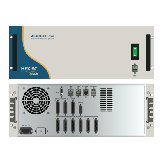
- Page 1 HEX RC Hardware Manual Revision: 1.00.00 AEROTECH. HEX RC Powered by USB2 USB3 ETHERNET FIREWIRE DIGITAL / ANALOG IO MPGA ESTOP MOTOR / FEEDBACK...
- Page 2 This manual contains proprietary information and may not be reproduced, disclosed, or used in whole or in part without the express written permission of Aerotech, Inc. Product names mentioned herein are used for identification purposes only and may be trademarks of their respective companies.
-
Page 3: Table Of Contents
2.4.2. Analog Output 1 2.4.3. Opto-Isolated Outputs 2.4.4. Opto-Isolated Inputs 2.5. DVI Connector 2.6. USB Connectors 2.7. Ethernet Connector 2.8. FireWire® Connector Chapter 3: Options 3.1. Emergency Stop (-EST3) 3.2. MPGA32 Connector Chapter 4: Maintenance 4.1. Power Board Assembly 4.2. Preventative Maintenance www.aerotech.com... -
Page 4: Table Of Contents
HEX RC Hardware Manual Table of Contents Appendix A: Warranty and Field Service Appendix B: Revision History Index www.aerotech.com... -
Page 5: List Of Figures
USB 2.0 Location Figure 2-29: USB 3.0 Location Figure 2-30: Ethernet Connection Figure 2-31: FireWire Location Figure 3-1: ESTOP Option Interface Figure 3-2: ESTOP (-EST3) Option Figure 3-3: ESTOP (-EST3) with MPGA32 Option Figure 3-4: MPGA32 Connector Location Figure 4-1: Power Board www.aerotech.com... -
Page 6: List Of Tables
Chassis Electrical Specifications Table 1-4: Servo Amplifier Electrical Specifications (MP) Table 1-5: Unit Weight Table 1-6: A3200 Drive and Software Compatibility Table 2-1: Main AC Power Input Voltages and Current Requirements Table 2-2: AC Power Cord Wiring Specifications Table 2-3: I/O and Signal Wiring Specifications... -
Page 7: Ec Declaration Of Conformity
Declaration of Conformity HEX RC Hardware Manual EC Declaration of Conformity Manufacturer Aerotech, Inc. Address 101 Zeta Drive Pittsburgh, PA 15238-2897 Product HEX RC Model/Types This is to certify that the aforementioned product is in accordance with the applicable requirements of the following Directive(s):... - Page 8 HEX RC Hardware Manual Declaration of Conformity This page intentionally left blank. viii www.aerotech.com...
-
Page 9: Safety Procedures And Warnings
7. All service and maintenance must be performed by qualified personnel. 8. This product is intended for light industrial manufacturing or laboratory use. Use of this product for unintended applications can result in injury and damage to the equipment. www.aerotech.com... - Page 10 HEX RC Hardware Manual Electrical Safety This page intentionally left blank. www.aerotech.com...
-
Page 11: Quick Installation Guide
The HEX RC is provided to the user fully configured for operation of a Hexapod, including servo tuning for the user's load requirements (if provided to Aerotech). For additional information about HEX RC , programming, utilities, and system operation see the A3200 Help file in the Aerotech folder of the Windows Start menu on the HEX RC. - Page 12 HEX RC Hardware Manual Quick Installation Guide This page intentionally left blank. www.aerotech.com...
-
Page 13: Chapter 1: Introduction
The HEX RC performs both current loop and servo loop closures digitally to ensure the highest level of positioning accuracy and performance. With the A3200 distributed control architecture, the HEX RC can connect and control up to 26 additional axes of servo, stepper, or piezo-driven stages. -
Page 14: Table 1-1: Feature Summary
Power Amplifier Bandwidth Selectable through software Minimum Load Inducatance 0.1 mH Operating Temperature 0 to 50°C Storage Temperature -30 to 85°C Weight 25 kg 1. Peak value of the sine wave; rms current for AC motors is 0.707* Apk Chapter 1 www.aerotech.com... -
Page 15: Table 1-2: Ordering Options
AC power source from motor (uses two relays for redundancy); contains one-second bus discharge resistors; operator risk assessment is the responsibility of the end user or integrator -SL1 Rack-mount slides Accessories (Ordered as a separate line item) MPGA32 Six-axis jog pendant www.aerotech.com Chapter 1... -
Page 16: Figure
(up to x6) Analog Input 0 ± ESTOP Encoder +5V / Common (optional) Motor (+, -, ) ESTOP Motor Power Heatsink Over Temperature Amplifier Control Amplifier AC Power Power Control Input Supply Power Figure 1-2: Functional Diagram Chapter 1 www.aerotech.com... -
Page 17: Electrical Specifications
+5 V is provided on all axis feedback connectors for encoder, Hall, and limit Auxiliary Power Outputs power. Power switch / breaker (10 A, Supplemental Protection only). Protection Fuses on motor bus supply transformer. Bus supply inrush current limit during power-on. Indicator (Power) Power switch contains a power-on indicator. www.aerotech.com Chapter 1... -
Page 18: Table 1-4: Servo Amplifier Electrical Specifications (Mp)
Modes of Operation Brushless; Brush; Stepper Output short circuit; Peak over current; RMS over current; Protective Features Over temperature; Control power supply under voltage; Power stage bias supply under voltage Optical and transformer isolation between control and power Isolation stages. Chapter 1 www.aerotech.com... -
Page 19: Mechanical Specifications
D A N G E R / H E A V Y : Refer to Table 1-5 for chassis mass specifications. The HEX RC exceeds 25 kg (55 lbs). Use both handles to carefully lift and carry the HEX RC. www.aerotech.com Chapter 1... -
Page 20: Table 1-5: Unit Weight
DIGITAL / ANALOG IO MPGA ESTOP MOTOR / FEEDBACK 447.6 [17.62] 444.5 [17.50] 482.6 [19.00] 476.2 [18.75] 8.3 [0.33] (TYP.) 466.0 [18.35] 463.5 [18.25] AEROTECH. HEX RC Powered by Drawing Number: 620E1422- Figure 1-3: Dimensions Table 1-5: Unit Weight Description Weight... -
Page 21: Environmental Specifications
Up to 2000 meters. Pollution Pollution degree 2 (normally only non-conductive pollution). Indoor use only. Audible Noise 71 db at 1 meter (rear fan and side fan) 77 db at 1 meter (rear fan and side fan) www.aerotech.com Chapter 1... -
Page 22: Drive And Software Compatibility
1.4. Drive and Software Compatibility The following table lists the available A3200 drives and which version of the A3200 software first supported the drive. Drives that list a specific version number in the Last Software Version column will not be supported after the listed version. -
Page 23: Chapter 2: Installation And Configuration
The system serial number label contains important information such as the: Customer order number (please provide this number when requesting product support) Drawing number System part number The AC power input label is located beside the AC power inlet and contains the factory configured AC power requirements. www.aerotech.com Chapter 2... -
Page 24: Electrical Installation
Digital / Analog I/O ESTOP MOTOR / FEEDBACK AC Power Input Motor / Feedback Figure 2-1: Power and Control Connections AEROTECH. Power Switch / Circuit Breaker HEX RC Powered by Figure 2-2: Power Switch All low voltage connections must be made using cables and wires sized for the maximum currents that will be carried. -
Page 25: Ac Power Connections
Table 2-2: AC Power Cord Wiring Specifications Specification Value Cord/Wire Rating 300 V Minimum Current Capacity 10 A Temperature Rating (Insulation) 80°C 1. The insulation rating for the AC power wiring must be appropriately rated for the operating environment. www.aerotech.com Chapter 2... -
Page 26: Minimizing Conducted, Radiated, And System Noise
2. Insulation rating will need to be rated for the higher voltage if the wiring is in proximity to wiring operating at voltages above 60 V. 3. Larger gauge wire may be required to minimize voltage drop due to voltage (IR) loss in the cable. Table 2-4: Recommended Wire Sizes Chapter 2 www.aerotech.com... -
Page 27: Motor Feedback Connections
Input Motor Thermistor Input Hall Effect sensor, phase B Input Frame ground Motor ØA Output Motor ØB Output Motor ØC Output Mating Connector Aerotech P/N Third Party P/N 25-Pin D-Connector ECK00101 FCI DB25P064TXLF Backshell ECK00656 Amphenol 17E-1726-2 www.aerotech.com Chapter 2... -
Page 28: Encoder Inputs
N O T E : Encoder wiring should be physically isolated from AC power and other high-voltage wiring. Table 2-6: Encoder Pin Assignment Pin# Description In/Out/Bi Cosine-N Input Sine-N Input Marker-N Input Common Cosine Input Sine Input Marker Input +5 V power supply Output Chapter 2 www.aerotech.com... -
Page 29: Square Wave (Rs-422) Encoder
10 MHz maximum (25 nsec minimum edge separation) x4 Quadrature Decoding 40 million counts/sec +3.3V COS+ PIN-14 COS- PIN-2 SIN+ PIN-15 SIN- PIN-3 ENCODER FAULT DS26LV32 DETECTION +3.3V MRK+ PIN-16 MRK- PIN-4 DS26LV32 Figure 2-3: Line Driver Encoder Interface www.aerotech.com Chapter 2... -
Page 30: Analog Encoder Interface
The HEX RC controller contains Ndrive MP10 drives with the MXU option. The drive is software-configured to accept analog encoder signals (refer to the A3200 Help file for information on the PositionFeedbackType and EncoderMultiplicationFactor parameters). The encoder interpolation factor is software-selectable (refer to the A3200 Help file). -
Page 31: Analog Encoder Signals
PIN-4 AD822 82PF 82PF 10UF 6.3V SIN+ PIN-15 82PF 82PF 82PF 82PF SIN- PIN-3 AD822 82PF 82PF 10UF 6.3V COS+ PIN-14 82PF 82PF 82PF 82PF COS- PIN-2 AD822 82PF 82PF 10UF 6.3V Figure 2-5: Analog Encoder Signals www.aerotech.com Chapter 2... -
Page 32: Encoder Phasing
N O T E : Encoder manufacturers may refer to the encoder signals as A, B, and Z. The proper phase rela- tionship between signals is shown in Figure 2-6. Figure 2-7: Position Feedback in the Diagnostic Display Chapter 2 www.aerotech.com... -
Page 33: Hall-Effect Inputs
Hall Effect sensor, phase A Input Hall Effect sensor, phase C Input Frame ground +5 V power supply Output Hall Effect sensor, phase B Input HALL A PIN-8 HALL B PIN-21 HALL C PIN-9 Figure 2-8: Hall-Effect Inputs www.aerotech.com Chapter 2... -
Page 34: Thermistor Input
The nominal trip value of the sensor is 1k Ohm. Table 2-10: Thermistor Interface Pin Assignment Pin# Description In/Out/Bi Motor Thermistor Input THERMISTOR PIN-20 Figure 2-9: Thermistor Input Chapter 2 www.aerotech.com... -
Page 35: End Of Travel Limit Inputs
End of Travel (EOT) limits are used to define the end of physical travel. The EOT limit inputs accept 5-24 VDC level signals. The active state of the EOT limits is software selectable (refer to the A3200 Help file). Limit directions are relative to the encoder polarity in the diagnostics display (refer to Figure 2-12). -
Page 36: End Of Travel Limit Phasing
CW and CCW inputs at the motor feedback connector. The logic level of the EOT limit inputs may be viewed in the Status Utility (shown in Figure 2-12). Figure 2-12: Limit Input Status Utility Chapter 2 www.aerotech.com... -
Page 37: Motor Output Interface
Section 2.3.5.2. Stepper Motors: refer to Section 2.3.5.3. Table 2-12: Motor Output Connections Pin# Description In/Out/Bi Frame ground Motor ØA Output Motor ØB Output Motor ØC Output Frame ground Motor ØA Output Motor ØB Output Motor ØC Output www.aerotech.com Chapter 2... -
Page 38: Brushless Motor Connections
Brushless Motor Phasing Brushless motors are commutated electronically by the controller, typically using Hall-effect devices. If you are using standard Aerotech motors and cables, motor phasing adjustments are not required and this section may be skipped. The controller requires that the Back-EMF of each motor phase be aligned with the corresponding Hall-effect signal. -
Page 39: Encoder And Hall Signal Diagnostics
The state of the encoder and Hall-effect device signals can be observed in the Status Utility. An “L” for the given Hall input indicates zero voltage or logic low, where a “H” indicates 5V or logic high. Figure 2-14: Encoder and Hall Signal Diagnostics www.aerotech.com Chapter 2... -
Page 40: Motor Phasing Oscilloscope Example
With the designations of the motor and Hall leads of a third party motor determined, the motor can now be connected to an Aerotech system. Connect motor lead A to motor connector A, motor lead B to motor connector B, and motor lead C to motor connector C. Hall leads should also be connected to their respective feedback connector pins (Hall A lead to the Hall A feedback pin, Hall B to Hall B, and Hall C to Hall C). -
Page 41: Dc Brush Motor Connections
5. Connect the motor lead from the voltmeter to the ØA motor terminal on the HEX RC. Connect the motor lead from the negative lead of the voltmeter to the ØC motor terminal on the HEX RC. N O T E : If using standard Aerotech motors and cables, motor and encoder connection adjustments are not required. -
Page 42: Stepper Motor Connections
Stepper Motor Configuration Stepper Motor Phasing N O T E : If using standard Aerotech motors and cables, motor and encoder connection adjustments are not required. A stepper motor can be run with or without an encoder. If an encoder is not being used, phasing is not necessary. -
Page 43: Digital And Analog I/O Connections
Input Output Common - Input Optically-Isolated Output 4 Output Optically-Isolated Output 5 Output Optically-Isolated Output 6 Output Optically-Isolated Output 7 Output Mating Connector Aerotech P/N Third Party P/N 25-Pin D-Connector ECK00101 FCI DB25P064TXLF Backshell ECK00656 Amphenol 17E-1726-2 www.aerotech.com Chapter 2... -
Page 44: Table 2-14: Differential Analog Input 1 Specifications
Differential Analog Inputs Connector Pin Assignment Pin# Description In/Out/Bi Analog Input 1+ (Differential) Input Analog Input 1- (Differential) Input Ground ANALOG IN1+ PIN-1 Shielded 64.9K .001 Cable Signal Source 16.2K ANALOG IN1- PIN-2 PIN-15 Figure 2-21: Analog Input 1 Chapter 2 www.aerotech.com... -
Page 45: Analog Output
-5 V to +5 V Output Current 5 mA Resolution (bits) 16 bits Resolution (volts) 153 µV Table 2-17: Analog Output Connector Pin Assignment Pin# Description In/Out/Bi Analog Output 1 Output Ground AOUT PIN-14 PIN-15 Figure 2-22: Analog Output 1 www.aerotech.com Chapter 2... -
Page 46: Opto-Isolated Outputs
It is important that the diode be installed correctly (normally reversed biased). Refer to Figure 2-24 for an example of a current sinking output with diode suppression and Figure 2- for an example of a current sourcing output with diode suppression. Chapter 2 www.aerotech.com... -
Page 47: Outputs Connected In Current Sourcing Mode
LOAD – OPTOOUT3 PIN-13 PIN-21 Opto-Outputs 4-7 not shown. Diode required on each output that drives an inductive device (coil), such as a relay. Connection required to minimize glitching. Figure 2-24: Outputs Connected in Current Sinking Mode www.aerotech.com Chapter 2... -
Page 48: Opto-Isolated Inputs
Input Optically-Isolated Input 1 Input Optically-Isolated Input 2 Input Optically-Isolated Input 3 Input Input Common for Opto-Inputs 4 - 7 Input Optically-Isolated Input 4 Input Optically-Isolated Input 5 Input Optically-Isolated Input 6 Input Optically-Isolated Input 7 Input Chapter 2 www.aerotech.com... -
Page 49: Inputs Connected To A Current Sourcing Device
Figure 2-25: Inputs Connected to a Current Sourcing Device OPTOIN COMMON 1 PIN-4 Input Switches OPTOIN0 5-24 VDC PIN-5 CONTROLLER OPTOIN1 PIN-6 OPTOIN2 PIN-7 OPTOIN3 PIN-8 Opto-Inputs 4-7 not shown. Figure 2-26: Inputs Connected to a Current Sinking Device www.aerotech.com Chapter 2... -
Page 50: Dvi Connector
HEX RC Hardware Manual Installation and Configuration 2.5. DVI Connector The DVI connector is a video display interface. USB2 USB3 ETHERNET FIREWIRE DIGITAL / ANALOG IO MPGA ESTOP MOTOR / FEEDBACK Figure 2-27: DVI Connector Location Chapter 2 www.aerotech.com... -
Page 51: Usb Connectors
Installation and Configuration HEX RC Hardware Manual 2.6. USB Connectors The HEX RC supplies three USB ports for peripheral device connection. AEROTECH. HEX RC Powered by Figure 2-28: USB 2.0 Location USB2 USB3 USB2 USB3 ETHERNET FIREWIRE DIGITAL / ANALOG IO MPGA ESTOP... -
Page 52: Ethernet Connector
MPGA ESTOP MOTOR / FEEDBACK Ethernet I/O Module or PC Ethernet HUB or Switch USB2 USB3 ETHERNET FIREWIRE DIGITAL / ANALOG IO MPGA ESTOP standard standard MOTOR / FEEDBACK CAT5 cable CAT5 cable Figure 2-30: Ethernet Connection Chapter 2 www.aerotech.com... -
Page 53: Firewire® Connector
Installation and Configuration HEX RC Hardware Manual 2.8. FireWire® Connector The FireWire interface allows the user to control up to 26 additional A3200 drives. Table 2-23: FireWire Repeaters (for cables exceeding 4.5 m (15 ft) specification) Part Number Description NFIRE-RPTR-1394A-1394A Extender for copper cable lengths greater than 4.5 m (15 feet). - Page 54 HEX RC Hardware Manual Installation and Configuration This page intentionally left blank. Chapter 2 www.aerotech.com...
-
Page 55: Chapter 3: Options
HEX RC options. Table 3-1: Options and Capabilities Option Section Description / Capabilities -SL1 Section 1.2. Rack mount slides -EST3 Section 3.1. ESTOP Sense Input EN ISO 13849-1, Category 2, Category 3 -JP1 and Section 3.2. Six-Axis Jog Pendant. MPGA32 www.aerotech.com Chapter 3... -
Page 56: Emergency Stop (-Est3)
ETHERNET FIREWIRE DIGITAL / ANALOG IO MPGA ESTOP MOTOR / FEEDBACK Figure 3-1: ESTOP Option Interface Table 3-2: ESTOP Option Mating Connector Mating Connector Aerotech P/N Third Party P/N 15-Pin D-Connector ECK00100 FCI DA15P064TXLF Backshell ECK01022 Amphenol 17E-1725-2 Chapter 3 www.aerotech.com... -
Page 57: Table 3-3: Estop Safety Ratings
Category 3, PL d Table 3-4: Relay Specifications ESTOP3 CR1 and CR2 Relay Part Number Aerotech: ECW01107 Sprecher & Schuh: CA7-16E-M31-24E AC-1 (resistive load) Rating of 32 A Turn On The coil requires 17.0 W to turn on (which is equal to 700 mA @ 24 V) On / Holding The coil requires 1.7 W on (holding) current (which is equal to 70 mA @ 24 V) -
Page 58: Estop (-Est3) With Mpga32 Option
N.C. ESTOP N.C. MOTORS DRIVE ASSEMBLY SAFETY MONITOR ESTOP OPTO RESET 15-PIN MALE "D" 15-PIN FEMALE "D" (ECK00100) (ECK00326) Motor BACKSHELL JACKSOCKET Power (ECK01022) (ECK00328) Supply User-Supplied Circuitry Shown for Reference. Figure 3-3: ESTOP (-EST3) with MPGA32 Option Chapter 3 www.aerotech.com... -
Page 59: Mpga32 Connector
The MPGA32 is the connector interface for a six-axis jog pendant. The MPGA32 input device provides the capability to manually fine-position up to six axes. Refer to the MPG hardware manual for more information (Aerotech P/N: EDO120). The ESTOP switch on the MPGA32 will have no functionality without the -EST3 option (refer to Figure 3-3). -
Page 60: Table 3-5: Mpga Connector Pin Assignments
4 Axis Switch 6 Axis Switch x10 Mult Switch Reserved Reserved ESTOP NC1 ESTOP NC2 Reserved 5 V Input Reserved X Axis Switch Z Axis Switch x1 Mult Switch x100 Mult Switch Reserved ESTOP NC1 ESTOP NC2 Chapter 3 www.aerotech.com... -
Page 61: Chapter 4: Maintenance
HEX RC Hardware Manual Chapter 4: Maintenance Aerotech does not recommend opening the HEX RC to access internal boards, fuses, or components. Contact the factory for more details. D A N G E R : Always disconnect the Mains power connection before opening the HEX RC chassis. -
Page 62: Power Board Assembly
ECK00213 ECK00213 MATE: ECK01577 Board Assembly MATE: ECK01577 Drawing Number: 690D1645, Rev. -1 Figure 4-1: Power Board Table 4-1: Component Select Component 100/115 VAC 200/230VAC Bipolar Unipolar SW1, SW2 BW4, BW6 Factory Select Installed Installed Factory Select Chapter 4 www.aerotech.com... -
Page 63: Preventative Maintenance
The electrical power must be disconnected from the HEX RC while cleaning. Do not allow cleaning substances or other fluids to enter the HEX RC or to get on to any of the connectors. Avoid cleaning labels to prevent removing the label information. www.aerotech.com Chapter 4... - Page 64 HEX RC Hardware Manual Maintenance This page intentionally left blank. Chapter 4 www.aerotech.com...
-
Page 65: Appendix A: Warranty And Field Service
Aerotech makes no warranty that its products are fit for the use or purpose to which they may be put by the buyer, whether or not such use or purpose has been disclosed to Aerotech in specifications or drawings previously or subsequently provided, or whether or not Aerotech’s... - Page 66 Aerotech's approval. On-site Warranty Repair If an Aerotech product cannot be made functional by telephone assistance or by sending and having the customer install replacement parts, and cannot be returned to the Aerotech service center for repair, and if Aerotech determines the problem could be warranty-related, then the following policy applies:...
-
Page 67: Appendix B: Revision History
Revision History HEX RC Hardware Manual Appendix B: Revision History Revision Description 1.00.00 New manual www.aerotech.com Appendix B... - Page 68 HEX RC Hardware Manual Revision History This page intentionally left blank. Appendix B www.aerotech.com...
-
Page 69: Index
Humidity Continuous Output Current specifications I/O and Signal Wiring Requirements DC Brush Motor Connections Inrush Current DC Brush Motor Phasing inspect Declaration of Conformity inspect all cables and connections dimensions Inspect cooling vents Drive and Software Compatibility www.aerotech.com... - Page 70 Noise User Power Supply specifications Output Voltage specifications utilities Peak Output Current specifications video display pendant Pollution Warnings Position Feedback in the Diagnostic Display Warranty and Field Service Power Amplifier Bandwidth specifications Powered Motor Phasing Preventative Maintenance programming Protection www.aerotech.com...
Need help?
Do you have a question about the A3200 and is the answer not in the manual?
Questions and answers