Sign In
Upload
Manuals
Brands
Aerotech Manuals
Controller
HPe 200
Aerotech HPe 200 Motion Controller Manuals
Manuals and User Guides for Aerotech HPe 200 Motion Controller. We have
2
Aerotech HPe 200 Motion Controller manuals available for free PDF download: Hardware Manual
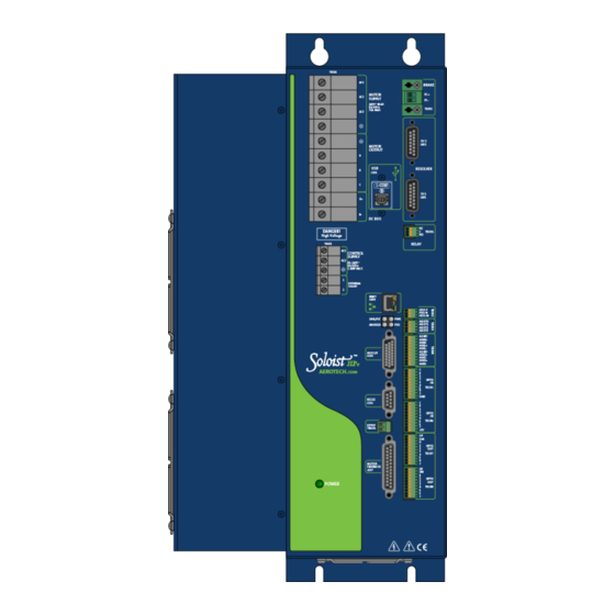
Aerotech HPe 200 Hardware Manual (126 pages)
Position Controllers and Drives
Brand:
Aerotech
| Category:
Controller
| Size: 1.98 MB
Table of Contents
Table of Contents
3
List of Figures
5
Table of Contents
5
Table of Contents
6
List of Tables
7
EC Declaration of Conformity
9
Ensemble Hpe
9
Agency Approvals
10
Safety Procedures and Warnings
11
Figure
13
Quick Installation Guide
13
Chapter 1: Introduction
15
Table 1-1: Feature Summary
16
Table 1-2: Accessories
17
Figure
18
Drive and Software Compatibility
19
Table 1-3: Ensemble Drive and Software Compatibility
19
Electrical Specifications
20
Table 1-4: Electrical Specifications
20
System Power Requirements
21
Mechanical Design
22
Table 1-5: Physical Specifications
23
Table 1-6: Heat Sink Specifications
23
Environmental Specifications
24
Chapter 2: Installation and Configuration
25
Power Connections
26
Control Supply Connections
27
Table 2-1: Control Supply AC Input Wiring
27
Figure
27
Motor Supply Connections
28
Figure
28
Minimizing Conducted, Radiated, and System Noise
29
Table 2-2: Motor Supply Input Wiring
29
Motor Output Connections
30
Table 2-3: Motor Power Output Connections
30
Brushless Motor Connections
31
Figure
31
Table 2-4: Wire Colors for Aerotech Supplied Cables (Brushless)
31
Powered Motor Phasing
32
Figure
33
Figure
34
Unpowered Motor and Feedback Phasing
34
Figure
35
Brushless Motor Phasing Goal
36
DC Brush Motor Connections
37
Table 2-5: Wire Colors for Aerotech Supplied Cables (DC Brush)
37
DC Brush Motor Phasing
38
Stepper Motor Connections
39
Table 2-6: Wire Colors for Aerotech Supplied Cables (Stepper)
39
Stepper Motor Phasing
40
Motor Feedback Connections (J207)
41
Table 2-7: Motor Feedback Connector Pin Assignment (J207)
41
Encoder Interface (J207)
42
Table 2-8: Encoder Interface Pin Assignment
42
Line Driver Encoder (Standard)
43
Endat Encoder Interface (J207)
44
Resolute Encoder Interface (J207)
45
Analog Encoder Interface
46
Table 2-9: Analog Encoder Specifications
46
Analog Encoder Interface (J207)
47
Encoder Phasing
48
Position Feedback in the Diagnostic Display
49
Hall-Effect Interface (J207)
50
Table 2-10: Hall-Effect Feedback Interface Pin Assignment (J207)
50
Table 2-11: Hall-Effect Feedback Interface Pin Assignment (J207)
51
Thermistor Interface (J207)
51
Encoder Fault Interface (J207)
52
Table 2-12: Encoder Fault Interface Pin Assignment (J207)
52
End of Travel Limit Input Interface (J207)
53
Table 2-13: End of Travel Limit Input Interface Pin Assignment (J207)
53
End of Travel Limit Interface Input (J207)
54
End of Travel Limit Phasing
55
Brake Output (J207)
56
Table 2-14: Brake Output Pin Assignment (J207)
56
Emergency Stop Sense Input (TB201)
57
Table 2-15: Electrical Noise Suppression Devices
57
Table 2-16: Electrical Noise Suppression Devices
57
Table 2-17: TB201 Mating Connector
57
Table 2-18: Typical ESTOP Relay Ratings
58
Typical ESTOP Interface
58
Auxiliary I/O Connector (J205)
59
Table 2-19: Auxiliary I/O Connector Pin Assignment (J205)
59
Auxiliary Encoder Channel (J205)
60
Table 2-20: Auxiliary Encoder Channel Pin Assignment (J205)
60
Auxiliary Encoder Channel (J205)
61
Position Synchronized Output (Pso)/Laser Firing (J205)
62
Table 2-21: PSO Output Pin Assignment (J205)
62
Table 2-22: PSO Output Sources
62
PSO Interface
63
Opto-Isolated Outputs 0-3 (J205)
64
Table 2-23: Port 0 Digital Output Connector Pin Assignment (J205)
64
Table 2-24: Digital Output Specifications
64
Outputs Connected in Current Sinking Mode (J205)
65
Opto-Isolated Inputs 0-3 (J205)
66
Table 2-25: Port 0 Digital Input Connector Pin Assignment (J205)
66
Table 2-26: PS2806-4 Opto-Device Specifications
66
Inputs Connected in Current Sinking Mode (J205)
67
High Speed User Inputs 4-5 (J205)
68
Table 2-27: Port 0 High Speed Digital Input Connector Pin Assignment (J205)
68
Table 2-28: Input Voltage Jumper Configuration
68
Analog Output 0 (J205)
69
Table 2-29: Analog Output Connector Pin Assignment (J205)
69
Analog Input 0 (J205)
70
Table 2-30: Analog Input Connector Pin Assignment (J205)
70
Brake Power Supply (TB202)
71
Table 2-31: Brake Output Connector Pin Assignment (TB202)
71
Table 2-32: Mating Connector (TB202)
71
Table 2-33: Brake Output Connector Pin Assignment (J207)
71
Brake Connected to J207
72
Brake Connected to TB202
73
Solid State Relay Specifications (TB202)
74
Table 2-34: Relay Specifications
74
Aeronet Interface (J209/J210)
75
Table 2-35: Aeronet Cable Part Numbers
75
Interface (J206)
76
Connector Pin Assignment (J206)
76
Port Connector Mating Connector (J206)
76
EXTSHUNT Option (TB101)
77
Table 2-38: Recommended Shunt Resistors and Wire Gauge
77
Table 2-39: Maximum Storage Energy
78
PC Configuration and Operation Information
80
Chapter 3: -I/O Expansion Board
81
Table 3-1: -IO Expansion Board Jumper Configuration
81
Table 3-2: -IO Option Board Fuse Information
81
Brake / Mechanical Relay (TB301)
82
Brake Configuration Jumpers
82
Mechanical Relay Specifications
82
Table 3-3: -IO Expansion Board Brake Jumper Configuration
82
Table 3-4: Voltage and Current Specifications (TB301)
82
Brake / Mechanical Relay Interface Connector
83
Table 3-5: Brake / Mechanical Relay Connector Pin Assignment (TB301)
83
Table 3-6: Mating Connector
83
Brake Connected to TB301
84
PSO Output Interface (TB302)
85
PSO Opto Output
86
DUALPSO and -TRIPLEPSO Laser Firing Options
87
Multi-Axis Firing
87
Two/Three Axis Laser Firing Interconnection
88
PSO Opto Output (Archive)
89
PSO Opto-Chip Installation
90
Analog Outputs (TB303)
91
Analog Inputs (TB304)
92
User Power (TB305, TB306)
93
Opto-Isolated Inputs (TB305, TB306)
94
Opto-Isolated Outputs (TB307, TB308)
97
Table 3-27: Output Specifications (TB307, TB308)
99
Ssinet (J302/J303)
101
Chapter 4: -RDP Expansion Board
103
Table 4-2: -RDP Connector Pin Assignment (J401/J402)
104
Table 4-4: Resolver Test Points
106
Chapter 5: Standard Interconnection Cables
107
Joystick Interface
108
Two Axis Joystick Interface (to the aux I/O and I/O
109
Handwheel Interface
110
Chapter 6: Maintenance
111
Power Board
112
Control Board
113
Table 5-4: Control Board Fuse Information
114
Preventative Maintenance
115
Appendix A: Warranty and Field Service
117
Appendix B: Revision History
119
Index
121
Advertisement
Aerotech HPe 200 Hardware Manual (108 pages)
Brand:
Aerotech
| Category:
DC Drives
| Size: 3.38 MB
Table of Contents
Soloist Hpe 150/200 Hardware Manual
1
Table of Contents
3
List of Figures
5
List of Tables
7
EU Declaration of Conformity
9
Agency Approvals
10
Safety Procedures and Warnings
11
Quick Installation Guide
13
Chapter 1: Introduction
15
Figure 1-1: Soloist Hpe 150/200 Networked Digital Drive
15
Table 1-1: Feature Summary
16
Table 1-2: Ordering Options
16
Table 1-3: Ordering Options (Continued)
17
Table 1-4: Accessories
17
Figure 1-2: Functional Diagram
18
Drive and Software Compatibility
19
Table 1-5: Drive and Software Compatibility
19
Electrical Specifications
20
Table 1-6: Electrical Specifications
20
System Power Requirements
21
Mechanical Design
22
Figure 1-3: Dimensions
22
Table 1-7: Physical Specifications
22
Environmental Specifications
23
Chapter 2: Installation and Configuration
25
Power Connections
25
Control Supply Connections
25
Figure 2-1: Control Supply Connections
25
Table 2-1: Control Supply AC Input Wiring
25
Motor Supply Connections
26
Figure 2-2: Motor Bus Input Connections
26
Minimizing Conducted, Radiated, and System Noise
27
Table 2-2: Ferrite Noise Suppression Part Numbers
27
Motor Output Connections
28
Table 2-3: Motor Power Output Connections
28
Brushless Motor Connections
29
Figure 2-3: Brushless Motor Configuration
29
Table 2-4: Wire Colors for Aerotech Supplied Cables (Brushless)
29
Powered Motor Phasing
30
Figure 2-4: Encoder and Hall Signal Diagnostics
30
Unpowered Motor and Feedback Phasing
31
Figure 2-5: Motor Phasing Oscilloscope Example
31
Figure 2-6: Brushless Motor Phasing Goal
31
DC Brush Motor Connections
32
Figure 2-7: DC Brush Motor Configuration
32
Table 2-5: Wire Colors for Aerotech Supplied Cables (DC Brush)
32
DC Brush Motor Phasing
33
Figure 2-8: Clockwise Motor Rotation
33
Stepper Motor Connections
34
Figure 2-9: Stepper Motor Configuration
34
Table 2-6: Wire Colors for Aerotech Supplied Cables (Stepper)
34
Stepper Motor Phasing
35
Figure 2-10: Clockwise Motor Rotation
35
Motor Feedback Connections (J207)
36
Table 2-7: Motor Feedback Connector Pinout (J207)
36
Table 2-8: Mating Connector Part Numbers for the Motor Feedback Connector (J207)
36
Encoder Interface (J207)
37
Table 2-9: Encoder Interface Pins on the Motor Feedback Connector (J207)
37
Line Driver Encoder (Standard)
38
Figure 2-11: Line Driver Encoder Interface (J207)
38
Table 2-10: Encoder Specifications
38
Absolute Encoder Interface (J207)
39
Figure 2-12: Serial Data Stream Interface
39
Analog Encoder Interface
40
Figure 2-13: Analog Encoder Phasing Reference Diagram
40
Table 2-11: Analog Encoder Specifications
40
Figure 2-14: Analog Encoder Interface (J207)
41
Encoder Phasing
42
Figure 2-15: Encoder Phasing Reference Diagram (Standard)
42
Figure 2-16: Position Feedback in the Diagnostic Display
43
Hall-Effect Interface (J207)
44
Figure 2-17: Hall-Effect Inputs (J207)
44
Table 2-12: Hall-Effect Feedback Interface Pins on the Motor Feedback Connector (J207)
44
Thermistor Interface (J207)
45
Figure 2-18: Thermistor Interface Input (J207)
45
Table 2-13: Thermistor Interface Pin on the Motor Feedback Connector (J207)
45
Encoder Fault Interface (J207)
46
Figure 2-19: Encoder Fault Interface Input (J207)
46
Table 2-14: Encoder Fault Interface Pin on the Motor Feedback Connector (J207)
46
End of Travel Limit Input Interface (J207)
47
Figure 2-20: End of Travel Limit Input Connections
47
Table 2-15: End of Travel Limit Input Interface Pins on the Motor Feedback Connector (J207)
47
Figure 2-21: End of Travel Limit Interface Input (J207)
48
End of Travel Limit Phasing
49
Figure 2-22: Limit Input Diagnostic Display
49
Brake Output (J207)
50
Table 2-16: Brake Output Pins on the Motor Feedback Connector (J207)
50
Emergency Stop Sense Input (TB201)
51
Figure 2-23: ESTOP Sense Input (TB201)
51
Table 2-17: Electrical Noise Suppression Devices
51
Table 2-18: Mating Connector Part Numbers for the ESTOP Connector (TB201)
51
Typical ESTOP Interface
52
Figure 2-24: Typical Emergency Stop Circuit
52
Table 2-19: Typical ESTOP Relay Ratings
52
Auxiliary I/O Connector (J205)
53
Table 2-20: Auxiliary I/O Connector Pinout (J205)
53
Table 2-21: Mating Connector Part Numbers for the Auxiliary I/O Connector (J205)
53
Auxiliary Encoder Channel (J205)
54
Table 2-22: Auxiliary Encoder Specifications
54
Table 2-23: Auxiliary Encoder Channel Pins on the Auxiliary I/O Connector (J205)
54
Figure 2-25: Auxiliary Encoder Channel (J205)
55
Position Synchronized Output (Pso)/Laser Firing (J205)
56
Table 2-24: PSO Specifications
56
Table 2-25: PSO Output Pins on the Auxiliary I/O Connector (J205)
56
Figure 2-26: PSO Interface
57
Digital Outputs 0-3 (J205)
58
Table 2-26: Digital Output Specifications
58
Table 2-27: Port 0 Digital Output Pins on the Auxiliary I/O Connector (J205)
58
Figure 2-27: Digital Outputs Connected in Current Sourcing Mode (J205)
59
Figure 2-28: Digital Outputs Connected in Current Sinking Mode (J205)
59
Digital Inputs 0-3 (J205)
60
Table 2-28: Digital Input Specifications
60
Table 2-29: Port 0 Digital Input Pins on the Auxiliary I/O Connector (J205)
60
Figure 2-29: Digital Inputs Connected in Current Sourcing Mode (J205)
61
Figure 2-30: Digital Inputs Connected in Current Sinking Mode (J205)
61
High-Speed Digital Inputs 4-5 (J205)
62
Figure 2-31: High-Speed User Inputs (J205)
62
Table 2-30: High-Speed Input Specifications
62
Table 2-31: Port 0 High-Speed Digital Input Pins on the Auxiliary I/O Connector (J205)
62
Table 2-32: Input Voltage Jumper Configuration
62
Analog Output 0 (J205)
63
Figure 2-32: Analog Output 0 (J205)
63
Table 2-33: Analog Output 0 Specifications (J205)
63
Table 2-34: Analog Output Pins on the Auxiliary I/O Connector (J205)
63
Differential Analog Input 0 (J205)
64
Figure 2-33: Analog Input 0 (J205)
64
Table 2-35: Differential Analog Input 0 Specifications
64
Table 2-36: Analog Input Pins on the Auxiliary I/O Connector (J205)
64
Brake Power Supply (TB202)
65
Table 2-37: Relay Specifications
65
Table 2-38: Brake Output Connector Pinout (TB202)
65
Table 2-39: Mating Connector Part Numbers for the Brake Power Supply Connector (TB202)
65
Figure 2-34: Brake Connected to J207
66
Figure 2-35: Brake Connected to TB202
66
Interface (J206)
67
EXTSHUNT Option (TB101)
68
Table 2-42: -EXTSHUNT Component Information
68
Table 2-43: Maximum Additional Storage Energy
69
PC Configuration and Operation Information
70
Chapter 3: -I/O Expansion Board
71
Figure 3-1: Soloist Hpe 150/200 with -IO Option Board
71
Table 3-1: -IO Expansion Board Jumper Configuration
71
Relay Connector (TB301)
72
Figure 3-2: Brake Connected to J207
73
Figure 3-3: Brake Connected to TB301
73
PSO Output Interface (TB302)
74
Figure 3-4: PSO Output Sources Current
74
Figure 3-5: PSO Output Sinks Current
74
Analog Outputs (TB303)
75
Figure 3-6: Analog Output Connector (TB303)
75
Analog Inputs (TB304)
76
Figure 3-7: Analog Input Typical Connection (TB304)
76
User Power (TB305, TB306)
77
Opto in Connecter (Digital Inputs) (TB305, TB306)
78
Figure 3-8: Digital Opto-Isolated Inputs
79
Figure 3-9: Digital Inputs Connected to a Current Sourcing Device
80
Figure 3-10: Digital Inputs Connected to a Current Sinking Device
80
Opto out Connector (Digital Outputs) (TB307, TB308)
81
Figure 3-11: Digital Opto-Isolated Outputs (-IO Board)
83
Figure 3-12: Digital Outputs Connected in Current Sourcing Mode
84
Chapter 4: -RDP Expansion Board
85
Chapter 5: Standard Interconnection Cables
89
Joystick Interface
90
Handwheel Interface
93
Chapter 6: Maintenance
95
Power Board
96
Control Board
97
Preventative Maintenance
99
Appendix A: Warranty and Field Service
101
Appendix B: Revision History
103
Index
105
Advertisement
Related Products
Aerotech HPe 150
Aerotech Ensemble HPe 10
Aerotech Ensemble HPe 20
Aerotech Ensemble HPe 30
Aerotech PLANAR HD-350-500
Aerotech PLANAR HD-350-650
Aerotech PLANAR HD-500-350
Aerotech PLANAR HD-500-500
Aerotech PLANAR HD-650-350
Aerotech PLANAR HD-650-650
Aerotech Categories
Industrial Equipment
DC Drives
Controller
Engine
Amplifier
More Aerotech Manuals
Login
Sign In
OR
Sign in with Facebook
Sign in with Google
Upload manual
Upload from disk
Upload from URL