Aerotech A3200 Hardware Manual
Nmark cls
Hide thumbs
Also See for A3200:
- Hardware manual (70 pages) ,
- Hardware manual (132 pages) ,
- Hardware manual (20 pages)
Table of Contents
Advertisement
Quick Links
Nmark CLS Hardware Manual
FIREWIRE
A
3
2 00
J101
Nmark CLS
AEROTECH.
J102
J103
AXIS 1
J201
PWR
STAT
TB101
C0-3
OP
O0
I0
I1
O1
O2
I2
O3
I3
C4-7
O4
O5
I4
O6
I5
I6
O7
OM
I7
TB102
O1-
+5
LP
O1+
O1
O2-
O2
O2+
O3
O3-
OC
O3+
OC
ES+
ES-
TB103
I3+
I0+
I0-
I3-
AXIS 2
I1+
O0
J202
I1-
O1
I2+
O2
I2-
+5
TB201
MOTOR SUPPLY
DC+
RET
DC-
ENCODER
OUTPUT
+/- 40V
J104
20A MAX
Patent Number: US 8,426,768 B2
Revision: 1.03.00
TM
COM
P/N: EDU217
Advertisement
Table of Contents

Related Manuals for Aerotech A3200


Summary of Contents for Aerotech A3200
-
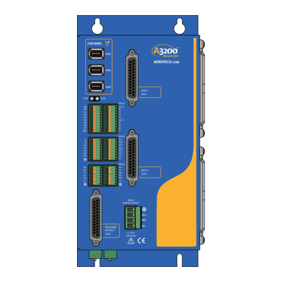
Page 1: Nmark Cls Hardware Manual
Nmark CLS Hardware Manual P/N: EDU217 Revision: 1.03.00 FIREWIRE 2 00 J101 Nmark CLS AEROTECH. J102 J103 AXIS 1 J201 STAT TB101 C0-3 C4-7 TB102 TB103 AXIS 2 J202 TB201 MOTOR SUPPLY ENCODER OUTPUT +/- 40V J104 20A MAX Patent Number: US 8,426,768 B2... - Page 2 This manual contains proprietary information and may not be reproduced, disclosed, or used in whole or in part without the express written permission of Aerotech, Inc. Product names mentioned herein are used for identification purposes only and may be trademarks of their respective companies.
-
Page 3: Table Of Contents
2.10. Digital I/O Connector Interface (TB107 A/B) 2.11. Auxiliary Encoder Interface (TB108) 2.12. Switch S1 (Laser Output Polarity/Configuration) 2.13. PC Configuration and Operation Information Chapter 3: Maintenance 3.1. Board Assembly 3.2. Preventative Maintenance Appendix A: Warranty and Field Service Appendix B: Revision History Index www.aerotech.com... -
Page 4: List Of Figures
Analog Outputs (TB103 B) Figure 2-22: Analog Inputs (TB103) Figure 2-23: Digital Inputs (TB107) Figure 2-24: Digital Outputs (TB107) Figure 2-25: Encoder Connections (TB108 A/B) Figure 2-26: Switch S1 (Laser Output Polarity/Configuration) Figure 3-1: Control Board Assembly Figure 3-2: Power Board Assembly www.aerotech.com... -
Page 5: List Of Tables
Axis 2 Auxiliary Encoder Interface Pin Assignment (TB108B) Table 2-40: Auxiliary Encoder Interface Mating Connector (TB108 A/B) Table 3-1: LED Description Table 3-2: Control Board Jumper Selections Table 3-3: Control Board Fuse Specifications Table 3-4: Power Board Fuses Table 3-5: Preventative Maintenance www.aerotech.com... - Page 6 Table of Contents Nmark CLS Hardware Manual This page intentionally left blank. www.aerotech.com...
-
Page 7: Eu Declaration Of Conformity
Nmark CLS Hardware Manual Declaration of Conformity EU Declaration of Conformity Manufacturer Aerotech, Inc. Address 101 Zeta Drive Pittsburgh, PA 15238-2897 Product Nmark CLS Model/Types This is to certify that the aforementioned product is in accordance with the applicable requirements of the... -
Page 8: Agency Approvals
Declaration of Conformity Nmark CLS Hardware Manual Agency Approvals Aerotech, Inc. Model Nmark CLS Drives have been tested and found to be in accordance to the following listed Agency Approvals: Approval / Certification: CUS NRTL Approving Agency: TUV SUD America Inc. -
Page 9: Safety Procedures And Warnings
N O T E : Aerotech continually improves its product offerings; listed options may be superseded at any time. All drawings and illustrations are for reference only and were complete and accurate as of this manual’s release. - Page 10 Nmark CLS Hardware Manual Electrical Safety This page intentionally left blank. www.aerotech.com...
-
Page 11: Quick Installation Guide
Nmark CLS. If a custom interconnection drawing was created for your system (look for a line item on your Sales Order under the heading “Integration”), that drawing can be found on your installation device. BOTTOM FIREWIRE 2 00 J101 Nmark CLS AEROTECH. J102 LASER OUTPUT POLARITY J103 AXIS 1 J201... - Page 12 Quick Installation Guide Nmark CLS Hardware Manual This page intentionally left blank. www.aerotech.com...
-
Page 13: Chapter 1: Introduction
Introduction Chapter 1: Introduction Aerotech’s Nmark CLS, part of the A3200 product family, is a closed-loop scanner module that allows direct control of galvo scanner servo motion for marking parts of unlimited size and complexity. The Nmark CLS has support for CO2 and YAG lasers and includes Position Synchronized Output (PSO) laser firing based on real-time scanner positional feedback. -
Page 14: Table 1-1: Feature Summary
Configure laser outputs as sourcing outputs (factory configuration, jumper settings cannot be changed in the field) -SINK Configure laser outputs as sinking outputs (factory configuration, jumper settings cannot be changed in the field) Table 1-2: Accessories Cables FireWire Section 2.3. FireWire Interface. Chapter 1 www.aerotech.com... -
Page 15: Figure 1-2: Functional Diagram
2 Auxiliary SIN +/- TB108 SIN+/- COS+/- (Axis 2) Output 2 Auxiliary COS +/- Auxiliary 2 Auxiliary MRK +/- Encoder +5V / Common TB201 Isolated TB109 Power Motor Power Supply Control Stages Supply Supply Figure 1-2: Functional Diagram www.aerotech.com Chapter 1... -
Page 16: 1.1. Electrical Specifications
±35 V @ 20 A Peak Output Current 20 A Continuous Output Current Minimum Load Resistance 0.5 Ω Output Impedance 0.25 Ω User Power Supply Output 5 VDC (@ 500 mA) Mode of Operation Galvo (1) Load Dependent Chapter 1 www.aerotech.com... -
Page 17: 1.2. Mechanical Design
The following figure shows the Nmark CLS package dimension as well as the typical mounting orientation. 113.4 [4.47] 18.6 [0.73] 76.2 [3.00] Ø4.7 [Ø0.19] (TYP) Ø10.3 [Ø0.41] (TYP) FIREWIRE 2 00 J101 Nmark CLS AEROTECH. J102 J103 AXIS 1 J201 STAT TB101 C0-3 C4-7 TB102... -
Page 18: 1.3. Environmental Specifications
Decreasing linearly to 50% relative humidity at 40°C. Non condensing. Operating: 0 m to 2,000 m (0 ft to 6,562 ft) above sea level Altitude Contact Aerotech if your specific application involves use above 2,000 m or below sea level. Pollution Pollution degree 2 (normally only non-conductive pollution). -
Page 19: 1.4. Drive And Software Compatibility
Nmark CLS 4.06.001 Current Nmark GCL 5.04.000 Current 2.21 Current Nmark SSaM 4.06.001 Current 1.07 2.55 Npaq 2.09 Current Npaq MR with ML drives 3.00 Current Npaq MR with MP drives 2.14 Current Nservo 2.08 Current Nstep 2.14 Current www.aerotech.com Chapter 1... - Page 20 Introduction Nmark CLS Hardware Manual This page intentionally left blank. Chapter 1 www.aerotech.com...
-
Page 21: Chapter 2: Installation And Configuration
Device Number Switch Settings (S2) Switch Settings (Off is indicated by "-") Device # Switch Location DEVICE NUMBER LASER OUTPUT POLARITY CONFIG DEVICE NUMBER WARNING: DISCONNECT POWER BEFORE SERVICING SEE MANUAL FOR SWITCH SETTINGS S/N - P/N - www.aerotech.com Chapter 2... -
Page 22: 2.2. Power Connections
Neutral if an external 2 A time-delay fuse is used. Although the control power supply contains an internal filter, an additional external filter located as close as possible to the Nmark CLS may be required for CE compliance (Aerotech recommends Schaffner FN2080). Line (L) -
Page 23: Motor Supply Connections (Tb201)
2.1 mm (#14 AWG) N O T E : Wire insulation rated for 300 V. Table 2-5: Motor Supply Mating Connector (TB201) Screw Torque Wire Size: Type Aerotech P/N Phoenix P/N Value: Nm [AWG] 4-Pin Terminal Block ECK01581 1757035 0.5 - 0.6 3.3 - 0.0516 [12-30]... -
Page 24: 2.2.3. External Power Supply Options
115~ 115~ 2nd CLS 4th CLS 24VDC 1A MAX – Transformer Module AEROTECH. DA N G E R ! High Voltage FOLLOW ALL APPLICABLE WIRING CONNECT ALL WIRING BEFORE HAZARDOUS VOLTAGES PRESENT AND SAFETY CODES. POWERING TRANSFORMER 1. The TM3 must be configured for a bipolar bus (-40B AUX AC). -
Page 25: 2.2.4. Minimizing Conducted Radiated And System Noise
The shield of the cables must be connected to the metal back shell in order for the product to conform to radiated emission standards. The Nmark CLS is a component designed to be integrated with other electronics. EMC testing must be conducted on the final product configuration. www.aerotech.com Chapter 2... -
Page 26: Firewire Interface
228 mm (9 in) long, 6 pin to 6 pin NCONNECT-10000-GOF 10 m (32.8 ft), glass fiber Optical cable NCONNECT-15000-GOF 15 m (49.2 ft), glass fiber Optical cable NCONNECT-20000-GOF 20 m (65.6 ft), glass fiber Optical cable NCONNECT-30000-GOF 30 m (101.7 ft), glass fiber Optical cable Chapter 2 www.aerotech.com... -
Page 27: Laser Interface (Tb102)
RS-422 differential signals. The open drain / open source setting is a factory configured option. N O T E : The three laser outputs are configured in the software; refer to the A3200 Help file for more information. -
Page 28: Figure 2-5: Laser Interface Outputs (Tb102)
Installation and Configuration Nmark CLS Hardware Manual Table 2-11: Laser Interface Connector Mating Connector (TB102) Wire Size: mm [AWG] Mating Connector Aerotech P/N Phoenix P/N 8-Pin Terminal Block ECK01386 1881383 0.5 - 0.080 [20-28] Table 2-12: Output Specifications (TB102) Specification... -
Page 29: Figure 2-6: Current Sinking Configuration (With Isolation)
Figure 2-6: Current Sinking Configuration (with Isolation) TB102 (A) Laser Input +3.3-24V no connection no connection ≥470 Ω S1-x OFF = Active Low S1-x ON = Active High -SINK Configuration Figure 2-7: Current Sinking Configuration (without Isolation) www.aerotech.com Chapter 2... -
Page 30: Figure 2-8: Current Sourcing Configuration (With Isolation)
-SRC Configuration Figure 2-8: Current Sourcing Configuration (with Isolation) TB102 (A) Laser Input +3.3-24V no connection ≥470 Ω S1-x OFF = Active High S1-x ON = Active Low -SRC Configuration Figure 2-9: Current Sourcing Configuration (without Isolation) Chapter 2 www.aerotech.com... -
Page 31: Emergency Stop Sense Input (Tb102)
Table 2-14. These devices are applied across the switched coil to suppress transient voltages. Table 2-14: Electrical Noise Suppression Devices Device Aerotech P/N Third Party P/N RC (.1uf / 200 ohm) Network EIC240 Electrocube RG1782-8 Varistor EID160 Littelfuse V250LA40A www.aerotech.com... -
Page 32: Position Synchronized Output (Pso)
Connect to laser common for sinking mode Input Connect to laser common for sinking mode Input Table 2-17: PSO Output Pin Assignment TB102 (B) Pin # Label Description In/Out/Bi Laser Output 1- / PSO Output Output Laser Output 1+ / PSO Output Output Chapter 2 www.aerotech.com... -
Page 33: Encoder Output (J104)
Output Axis 2 Cosine + Output PSO External Sync Input No Connection No Connection No Connection No Connection No Connection Signal Common Mating Connector Aerotech P/N Third Party P/N 25-Pin D-Connector ECK00101 FCI DB25P064TXLF Backshell ECK00656 Amphenol 17E-1726-2 www.aerotech.com Chapter 2... -
Page 34: Figure 2-11: Encoder Outputs
AXIS 1 COS- J104-3 AXIS 2 SIN+ J104-17 AXIS 2 SIN- J104-4 AXIS 2 COS+ J104-18 AXIS 2 COS- J104-5 DS26LV31T Figure 2-11: Encoder Outputs +3.3V +3.3V 100Ω J104-19 100Ω 100Ω J104-25 DS26LV32AT Figure 2-12: PSO External Sync Input Chapter 2 www.aerotech.com... -
Page 35: Galvo Connections (J201 And J202)
Cosine 2- / Position Detector B- Input Reserved Marker 1- Input Encoder Ground Fan Power - Shield Motor - Output Motor - Output Mating Connector Aerotech P/N Third Party P/N 25-Pin D-Connector ECK00101 FCI DB25P064TXLF Backshell ECK00656 Amphenol 17E-1726-2 www.aerotech.com Chapter 2... -
Page 36: Analog Encoder Inputs (J201 And J202)
Encoder signals for each channel should be adjusted using the Feedback Tuning tab of the Digital Scope utility, which will automatically adjust the encoder parameters for optimum performance (refer to the A3200 Help file for more information). Table 2-20:... -
Page 37: Figure 2-13: Analog Encoder Input Schematic
J201-17 10PF 220PF 4.7K COS2- J201-18 COS1- J201-15 2.43K AD8656 .0018 .0018 4.7K 33PF +2.4V REF 10UF 6.3V MRK1+ J201-7 8.06K 82PF MRK1- J201-20 10PF MAX991 AD8656 +2.4V REF 82PF 10PF Figure 2-13: Analog Encoder Input Schematic www.aerotech.com Chapter 2... -
Page 38: Position Detector Inputs (J201 And J202)
The difference between the positive sense and the negative sense inputs determines the absolute position. When interfacing to an Aerotech AGV Galvo, the feedback sensitivity is 5255.4888 counts / degree. 100PF CH1 PD A-... -
Page 39: Fan Power Supply (J201 And J202)
2.6.3. Fan Power Supply (J201 and J202) A user accessible power supply (+24V, 500mA) is available to provide power for a fan. 2.6.4. Galvo Motor Connection (J201 and J202) The Nmark CLS is capable of controlling a DC Brush motor only. www.aerotech.com Chapter 2... -
Page 40: Opto-Isolated Outputs (Tb101 A)
Output Output 7 (Optically-Isolated) Output Output Common Minus Input Table 2-22: Opto-Isolated Output Connector Mating Connector (TB101 A/B) Wire Size: AWG [mm Aerotech P/N Phoenix P/N 10-Pin Terminal Block ECK01294 1881406 20-28 [0.5-0.080] Table 2-23: Opto-Isolated Output Specifications (TB101) Opto Device Specifications... -
Page 41: Figure 2-15: Opto-Isolated Outputs (Tb101 A)
OUTPUT6 TB101-A8 SMD005F OUTPUT5 TB101-A7 SMD005F OUTPUT4 TB101-A6 SMD005F PS2802-4 10UF 35V OUTPUT3 TB101-A5 SMD005F OUTPUT2 TB101-A4 SMD005F OUTPUT1 TB101-A3 SMD005F OUTPUT0 TB101-A2 SMD005F PS2802-4 Negative Power Supply TB101-A10 PS2802-4 PS2802-4 Figure 2-15: Opto-Isolated Outputs (TB101 A) www.aerotech.com Chapter 2... -
Page 42: Figure 2-16: Outputs Connected In Current Sourcing Mode
OUTPUT 0 TB101-A2 OUTPUT COMMON - TB101-A10 CONNECTION REQUIRED EACH OUTPUT 60 mA MAXIMUM DIODE REQUIRED ON EACH OUTPUT THAT DRIVES AN INDUCTIVE DEVICE (COIL), SUCH AS A RELAY. Figure 2-17: Outputs Connected in Current Sinking Mode Chapter 2 www.aerotech.com... -
Page 43: Opto-Isolated Inputs (Tb101 B)
Input Common for Inputs 4-7 Input Input 4 Input Input 5 Input Input 6 Input Input 7 Input Table 2-26: Opto-Isolated I/O Connector Mating Connector (TB101 A/B) Wire Size: AWG [mm Aerotech P/N Phoenix P/N 10-Pin Terminal Block ECK01294 1881406 20-28 [0.5-0.080] www.aerotech.com Chapter 2... -
Page 44: Figure 2-18: Opto-Isolated Inputs (Tb101 B)
TB101-B1 OPTOIN0 TB101-B2 4.02K OPTOIN1 TB101-B3 4.02K OPTOIN2 TB101-B4 4.02K OPTOIN3 TB101-B5 4.02K PS2806-4 +3.3V COMMON (4-7) TB101-B6 OPTOIN4 TB101-B7 4.02K OPTOIN5 TB101-B8 4.02K OPTOIN6 TB101-B9 4.02K OPTOIN7 TB101-B10 4.02K PS2806-4 Figure 2-18: Opto-Isolated Inputs (TB101 B) Chapter 2 www.aerotech.com... -
Page 45: Figure 2-19: Inputs Connected To A Current Sourcing Device
5-24 VDC TB101-B2 INPUT 1 TB101-B3 INPUT 2 TB101-B4 INPUT 3 TB101-B5 COMMON (4-7) TB101-B6 INPUT 4 5-24 VDC TB101-B7 INPUT 5 TB101-B8 INPUT 6 TB101-B9 INPUT 7 TB101-B10 Figure 2-20: Inputs Connected to a Current Sinking Device www.aerotech.com Chapter 2... -
Page 46: Analog I/O Interface (Tb103 A/B)
Analog Output 2 Output +5V Output Power Output Analog Common Table 2-29: Analog I/O Connector Mating Connector (TB103 A/B) Wire Size: mm [AWG] Type Aerotech P/N Phoenix P/N 7-Pin Terminal Block ECK01631 1881370 0.5 - 0.080 [20-28] Chapter 2 www.aerotech.com... -
Page 47: Analog Outputs (Tb103 B)
Output Voltage -10 V to +10 V Output Current 5 mA Resolution (bits) 16 bits Resolution (volts) 305 µV .001 4.99K ANALOG OUTPUT 0 AD5441 TB103-B3 AD8512 AOUT0 TB103-B3 AOUT1 TB103-B4 AOUT2 TB103-B5 Figure 2-21: Analog Outputs (TB103 B) www.aerotech.com Chapter 2... -
Page 48: Differential Analog Inputs (Tb103 A/B)
ANALOG INPUT 0+ TB103-A1 SHIELDED CABLE SIGNAL SOURCE ANALOG INPUT 0- AD622 TB103-A2 -12VA AIN0+ TB103-A1 AIN2+ TB103-A5 AIN0- TB103-A2 AIN2- TB103-A6 AIN1+ TB103-A3 AIN3+ TB103-B1 AIN1- TB103-A4 AIN3- TB103-B2 TB103-A7 ANALOG COMMON Figure 2-22: Analog Inputs (TB103) Chapter 2 www.aerotech.com... -
Page 49: Digital I/O Connector Interface (Tb107 A/B)
Digital Input 9 Input No Connection Digital Output 9 Output Table 2-36: Digital I/O Connector Mating Connector (TB107 A/B) Wire Size: mm [AWG] Mating Connector Aerotech P/N Phoenix P/N 8-Pin Terminal Block ECK01386 1881383 0.5 - 0.080 [20-28] www.aerotech.com Chapter 2... -
Page 50: Figure 2-23: Digital Inputs (Tb107)
74LCX16244 TB107-A6 DIN10 TB107-A5 DIN12 TB107-A4 DIN14 TB107-A3 +5V Output Power TB107-A1 +5V Output Power TB107-B1 GROUND TB107-A2 GROUND TB107-B2 Figure 2-23: Digital Inputs (TB107) DOUT8 TB107-A8 74AHCT1G14 FPGA DOUT9 TB107-B8 74AHCT1G14 Figure 2-24: Digital Outputs (TB107) Chapter 2 www.aerotech.com... -
Page 51: Auxiliary Encoder Interface (Tb108)
MRK+ Encoder MRK+ Input Input MRK- Encoder MRK- Input Input Table 2-40: Auxiliary Encoder Interface Mating Connector (TB108 A/B) Wire Size: mm [AWG] Mating Connector Aerotech P/N Phoenix P/N 8-Pin Terminal Block ECK01386 1881383 0.5 - 0.080 [20-28] www.aerotech.com Chapter 2... -
Page 52: Figure 2-25: Encoder Connections (Tb108 A/B)
MRK1 MRK1- TB108-A8 DS26LV32AT +3.3V +3.3V SIN2+ TB108-B3 SIN2 SIN2- TB108-B4 COS2+ TB108-B5 COS2 COS2- TB108-B6 MRK2+ TB108-B7 MRK2 MRK2- TB108-B8 DS26LV32AT TB108-A1 TB108-B1 Encoder Fault Detection GROUND TB108-A2 GROUND TB108-B2 Figure 2-25: Encoder Connections (TB108 A/B) Chapter 2 www.aerotech.com... -
Page 53: Switch S1 (Laser Output Polarity/Configuration)
Define the active laser output polarity using the Laser Output Polarity switches of S1 (see Section 2.4.). LASER OUTPUT POLARITY CONFIG LASER OUTPUT POLARITY CONFIG DEVICE NUMBER WARNING: DISCONNECT POWER BEFORE SERVICING SEE MANUAL FOR SWITCH SETTINGS S/N - P/N - Figure 2-26: Switch S1 (Laser Output Polarity/Configuration) www.aerotech.com Chapter 2... -
Page 54: 2.13. Pc Configuration And Operation Information
Installation and Configuration Nmark CLS Hardware Manual 2.13. PC Configuration and Operation Information For additional information about PC configuration, hardware requirements, programming, utilities, and system operation refer to the A3200 Help file. Chapter 2 www.aerotech.com... -
Page 55: Chapter 3: Maintenance
Turns green to indicate the laser output is firing. Turns red to indicate a fault condition on any axis. * If the power light flashes continuously and the unit does not operate, there is too much current draw from the 5V power supply or the control supply voltage level is low. www.aerotech.com Chapter 5... -
Page 56: 3.1. Board Assembly
TP45 TP52 TP51 TP50 TP49 TP48 TP36 TP35 TP34 TP33 TP32 TP31 TP30 TP29 0 OHM 2ASB TR5 TP15 TP19 SOCKET EIF01025 TP14 TP18 TP13 TP17 TP12 TP16 PAD1 Drawing Number: 690D1634 Figure 3-1: Control Board Assembly Chapter 5 www.aerotech.com... -
Page 57: Table 3-2: Control Board Jumper Selections
Laser Output 1 (O1) Sinking Laser Output 1 (O1) Sourcing (1) Default Table 3-3: Control Board Fuse Specifications Fuse Description Size Aerotech P/N Manufacturer's P/N Control Power at TB109-1 2 A S.B. EIF01029 Littelfuse 3721200041 FireWire power at J101-103 EIF01001 Raychem RGE300 NOTE: F3 is a resettable fuse (turn off power and remove the short. -
Page 58: Figure 3-2: Power Board Assembly
TP28 Drawing Number: 690D1681 Figure 3-2: Power Board Assembly Table 3-4: Power Board Fuses Fuse Description Size Aerotech P/N Manufacturer's P/N Motor Output (Channel 2) 10 A S.B. EIF01035 Littelfuse 374210 Motor Output (Channel 1) 10 A S.B. EIF01035 Littelfuse 374210 Motor Bus Supply (B-) 20 A S.B. -
Page 59: 3.2. Preventative Maintenance
The electrical power must be disconnected from the Nmark CLS while cleaning. Do not allow cleaning substances or other fluids to enter the Nmark CLS or to get on to any of the connectors. Avoid cleaning labels to prevent removing the label information. www.aerotech.com Chapter 5... - Page 60 Troubleshooting Nmark CLS Hardware Manual This page intentionally left blank. Chapter 5 www.aerotech.com...
-
Page 61: Appendix A: Warranty And Field Service
Aerotech makes no warranty that its products are fit for the use or purpose to which they may be put by the buyer, whether or not such use or purpose has been disclosed to Aerotech in specifications or drawings previously or subsequently provided, or whether or not Aerotech’s... - Page 62 Aerotech's approval. On-site Warranty Repair If an Aerotech product cannot be made functional by telephone assistance or by sending and having the customer install replacement parts, and cannot be returned to the Aerotech service center for repair, and if Aerotech determines the problem could be warranty-related, then the following policy applies:...
-
Page 63: Appendix B: Revision History
Added Input Power equation: Section 1.1. 1.01.00 Added Torque Tightening specifications: Table 2-3 Table 2-5 Updated documentation for J104: Section 2.5. Updated Control Supply Connection section: Section 2.2.1. Updated FireWire cables: Section 2.3. Updated Output Specifications: Table 2-12 1.00.00 New Manual www.aerotech.com Appendix B... - Page 64 Revision History Nmark CLS Hardware Manual This page intentionally left blank. Appendix B www.aerotech.com...
-
Page 65: Index
Drive and Software Compatibility Pollution Electrical Specifications Power Connections Encoder Interface (TB108) Preventative Maintenance Environmental Specifications PSO Output Sources ESTOP Quick Installation Guide Feature Summary Quick Start Connections FireWire Cables FireWire Card Part Numbers FireWire Interface FireWire Repeaters www.aerotech.com Index... - Page 66 Index Nmark CLS Hardware Manual Standard Features Support TB101 B TB102 27,31 TB103 46,48 TB107 TB108 TB109 TB201 Technical Support Index www.aerotech.com...
Need help?
Do you have a question about the A3200 and is the answer not in the manual?
Questions and answers