Table of Contents
Advertisement
Quick Links
Advertisement
Chapters
Table of Contents
Troubleshooting

Related Manuals for Aerotech UNIDEX 511


Summary of Contents for Aerotech UNIDEX 511
- Page 1 Artisan Technology Group is your source for quality new and certified-used/pre-owned equipment SERVICE CENTER REPAIRS WE BUY USED EQUIPMENT • FAST SHIPPING AND DELIVERY Experienced engineers and technicians on staff Sell your excess, underutilized, and idle used equipment at our full-service, in-house repair center We also offer credit for buy-backs and trade-ins •...
- Page 2 OTION ONTROLLER USER’S MANUAL P/N: EDU162 (V1.1) AEROTECH, Inc. • 101 Zeta Drive • Pittsburgh, PA. 15238-2897 • USA Phone (412) 963-7470 • Fax (412) 963-7459 Product Service: (412) 967-6440; (412) 967-6870 (Fax) www.aerotechinc.com Artisan Technology Group - Quality Instrumentation ... Guaranteed | (888) 88-SOURCE | www.artisantg.com...
- Page 3 If you should have any questions about the UNIDEX 511 Motion Controller or comments regarding the documentation, please refer to Aerotech online at: http://www.aerotechinc.com. For your convenience, a product registration form is available at our web site. Our web site is continually updated with new product information, free downloadable software and special pricing on selected products.
-
Page 4: Table Of Contents
U511 User’s Manual Table of Contents TABLE OF CONTENTS CHAPTER 1: INTRODUCTION ................1-1 1.1. Overview of the UNIDEX 511 System..........1-1 1.2. Ordering Information................1-3 1.3. Options and Accessories..............1-4 1.4. Safety Procedures and Warnings ............1-5 CHAPTER 2: GETTING STARTED.............. - Page 5 “In position deadband” (machine steps) ......4-25 4.5.9. “Backlash correction amount” (machine steps) ....4-26 4.5.10. “Joystick high speed” (machine steps/sec) ......4-27 Aerotech, Inc. Version 1.1 Artisan Technology Group - Quality Instrumentation ... Guaranteed | (888) 88-SOURCE | www.artisantg.com...
- Page 6 “Commutation cycles/rev” (AC brushless motors only)..4-61 4.8.8. “Feedback steps/rev” (AC brushless motors only) ..... 4-62 4.8.9. “Commutation phase offset” (0-359 degrees) ....4-62 Aerotech, Inc. Version 1.1 Artisan Technology Group - Quality Instrumentation ... Guaranteed | (888) 88-SOURCE | www.artisantg.com...
- Page 7 4.11.13. “Clamp feedrate” (program steps/ms) ........4-98 4.11.14. “Corner rounding time” (1-32,000 ms) ........4-98 4.11.15. “Metric digits” (1-8)..............4-101 4.11.16. “English digits” (1-8) .............. 4-102 Aerotech, Inc. Version 1.1 Artisan Technology Group - Quality Instrumentation ... Guaranteed | (888) 88-SOURCE | www.artisantg.com...
- Page 8 5.5.23. DS (Display Servo Loop Data) .......... 5-37 5.5.24. DWELL................5-38 5.5.25. DY (Dynamic Gain) ............5-38 5.5.26. ENABLE................5-39 5.5.27. ERROR ................5-40 Aerotech, Inc. Version 1.1 Artisan Technology Group - Quality Instrumentation ... Guaranteed | (888) 88-SOURCE | www.artisantg.com...
- Page 9 5.5.70. SEGMENT................. 5-79 5.5.71. SKEY (Soft Keys) .............. 5-80 5.5.72. SLEW................. 5-81 5.5.73. SOFTWARE ..............5-83 5.5.74. SPLINE ................5-84 5.5.75. START ................5-85 Aerotech, Inc. viii Version 1.1 Artisan Technology Group - Quality Instrumentation ... Guaranteed | (888) 88-SOURCE | www.artisantg.com...
- Page 10 6.4.18. RVn: Read Variable ............6-23 6.4.19. DFfilename: Delete File ............. 6-24 6.4.20. HE [cmd]: Help Menu............6-24 6.4.21. GV: Software Version ............6-25 6.5. UNIDEX 511 Remote Timing............6-26 6.6. C Program Example................6-27 Aerotech, Inc. Version 1.1 Artisan Technology Group - Quality Instrumentation ... Guaranteed | (888) 88-SOURCE | www.artisantg.com...
- Page 11 7.6.3. Loading DOS or BIOS ............7-10 7.6.4. Erasing B Drive..............7-10 7.6.5. Uploading a File (to UNIDEX 511) ........7-10 7.6.6. Downloading a file (from UNIDEX 511)......7-11 CHAPTER 8: TUNING SERVO LOOPS ............... 8-1 8.1. Introduction ..................8-1 8.2.
- Page 12 Control Board Jumpers..............10-17 10.3. Interface Board Jumpers..............10-19 10.4. Encoder Specifications ..............10-21 10.5. UNIDEX 511 Control Board Test Points (TP1-TP25)....10-22 10.6. “PSO Encoder Bus” Connector (P6) ..........10-23 10.7. UNIDEX 511 Mechanical Specifications........10-24 10.7.1. UNIDEX 511 Desktop Specifications......10-24 10.7.2.
- Page 13 APPENDIX G: THE RDP-PC RESOLVER-TO-DIGITAL BOARD ....G-1 G.1. Introduction ..................G-1 G.2. RDP Board Hardware Setup.............. G-1 G.3. Installing the RDP Board into the UNIDEX 511....... G-6 G.4. UNIDEX 511 Software Setup............G-7 G.5. Connecting the Device to the RDP Board ......... G-8 G.6.
- Page 14 List of Figures LIST OF FIGURES Figure 1-1. UNIDEX 511..................1-1 Figure 1-2. The UNIDEX 511 System Diagram ........... 1-2 Figure 2-1. Flowchart Overviewing the Installation/Configuration Process ..2-2 Figure 2-2. Rear Panel Connectors of the U511............ 2-3 Figure 3-1.
- Page 15 Illustration of No Corner Rounding (G24) ........5-76 Figure 5-9. Illustration of Corner Rounding (G23) ..........5-76 Figure 5-10. Optional UNIDEX 511 Joystick, JI Model Left, JBV Model Right ....................5-81 Figure 5-11. Plot of Velocity Without Velocity Profiling ........5-93 Figure 5-12.
- Page 16 U511 User’s Manual List of Figures Figure 7-5. The Diagnostics Window ..............7-5 Figure 8-1. UNIDEX 511 Servo Loop ..............8-2 Figure 8-2. Axis Scope Window ................8-3 Figure 8-3. Cursors Toolbar of the Axis Scope Window ........8-8 Figure 8-4.
- Page 17 Pinouts on the PB24 I/O Card ........D-4 Figure G-1. RDP-PC Board .................. G-2 Figure G-2. RDP Board Connection to UNIDEX 511 Board ....... G-6 Figure G-3. Mating DB37 Connector..............G-8 Figure G-4. Suggested Cabling from RDP Board to Resolver or Inductosyn ..G-9 Figure G-5.
- Page 18 LIST OF TABLES Table 1-1. Basic Motion Controllers ..............1-3 Table 1-2. Available Motor Drivers compatible with UNIDEX 511 ....1-4 Table 1-3. Options and Accessories Available for the UNIDEX 511....1-4 Table 2-1. Servo Loop Tuning Parameters ............2-6 Table 3-1.
- Page 19 Motor Feedback Parameters ............. 4-49 Table 4-40. Commutation Factors for 4, 6, and 8 Poles........4-53 Table 4-41. Factory Configuration for UNIDEX 511 RDP ......... 4-54 Table 4-42. RDP Resolution and Setup Codes ............ 4-55 Table 4-43. Settings for Parameter x38..............4-56 Table 4-44.
- Page 20 Real Time Feedback Position Registers ..........5-6 Table 5-8. Real Time Commanded Position Registers ........5-7 Table 5-9. A/D Channel Registers ............... 5-8 Table 5-10. UNIDEX 511 Programming Commands ..........5-9 Table 5-11. Optional Arguments................5-16 Table 5-12. Comparison Operators..............5-49 Table 5-13.
- Page 21 COM2 Interface Connector Pin Connections ........10-4 Table 10-4. 16 IN/8 OUT Connector ..............10-5 Table 10-5. UNIDEX 511/Opto 22 Connection Information....... 10-6 Table 10-6. 8 X 3 I/O Bus Connector Pinouts (J12) .......... 10-10 Table 10-7. Control Board Current Limiting Resistor Locations for Opto- isolated Inputs.................
- Page 22 Setting “Primary feedback setup code” (x40) for the RDP Board..G-7 Table G-10. RDP Board Pinouts ................G-8 Table G-11. RDP Board Test Points..............G-10 ∇ ∇ ∇ Aerotech, Inc. Version 1.1 Artisan Technology Group - Quality Instrumentation ... Guaranteed | (888) 88-SOURCE | www.artisantg.com...
- Page 23 List of Tables U500 User’s Manual Aerotech, Inc. xxii Version 1.1 Artisan Technology Group - Quality Instrumentation ... Guaranteed | (888) 88-SOURCE | www.artisantg.com...
-
Page 24: Chapter 1: Introduction
This manual contains information on the following topics: CHAPTER 1: INTRODUCTION Chapter 1 contains an overview of the UNIDEX 511 motion control system, as well as a sample system diagram. This chapter also contains precautionary notes about installing and using the UNIDEX 511 motion control system. - Page 25 This chapter contains sample applications highlighting UNIDEX 511 features, parameter settings, and sample programs. CHAPTER 10: HARDWARE DETAILS Chapter 10 supplies a variety of technical specifications for the UNIDEX 511. These specifications include test points, jumper configurations, encoder signal specifications, pinouts, outputs, bus specifications, and others.
- Page 26 When mixed with small letters, capitalized letters within a command indicate the minimum entry for that command (e.g., DIsable). Most commands are given in capital letters. • The terms UNIDEX 511 and U511 are used interchangeably throughout this manual. • Italic font is used to illustrate syntax and arguments for programming commands.
- Page 27 Protection ground connection symbol “ ” WARNING • This manual uses the symbol “∇ ∇ ∇” to indicate the end of a chapter. ∇ ∇ ∇ Aerotech, Inc. xxvi Version 1.1 Artisan Technology Group - Quality Instrumentation ... Guaranteed | (888) 88-SOURCE | www.artisantg.com...
-
Page 28: Overview Of The Unidex 511 System
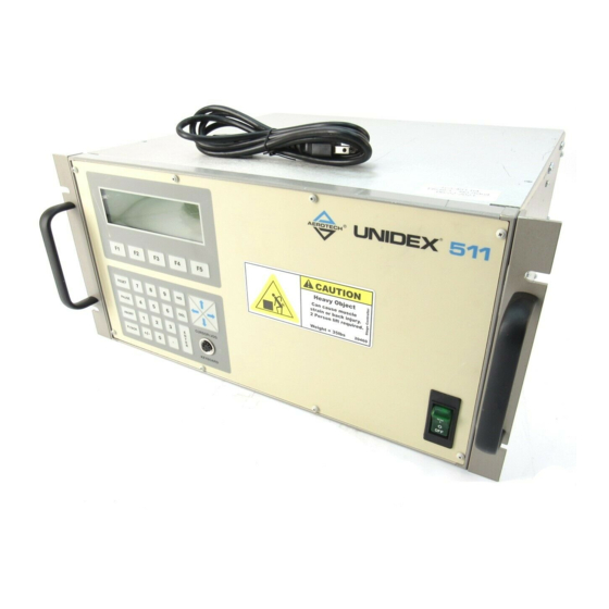
1.1. Overview of the UNIDEX 511 System The UNIDEX 511 (or U511) system is a stand-alone multiaxis motion controller (refer to Figure 1-1). The U511 controller contains up to four integral amplifiers and all the circuitry necessary to interface with up to four positioning stages. The UNIDEX 511 contains 48 digital I/O lines, two serial ports, an IEEE-488 parallel port, joystick interface, and the ability to support ISA expansion boards. -
Page 29: Figure 1-2. The Unidex 511 System Diagram
Introduction U511 User’s Manual Figure 1-2. The UNIDEX 511 System Diagram Aerotech, Inc. Version 1.1 Artisan Technology Group - Quality Instrumentation ... Guaranteed | (888) 88-SOURCE | www.artisantg.com... -
Page 30: Ordering Information
40 = 40 VDC 80 = 80 VDC 160 = 160 VDC Table 1-2 lists the Aerotech motor drivers that can be used with the UNIDEX 511. Aerotech, Inc. Version 1.1 Artisan Technology Group - Quality Instrumentation ... Guaranteed | (888) 88-SOURCE | www.artisantg.com... -
Page 31: Options And Accessories
1.3. Options and Accessories A variety of options and accessories may be purchased with the UNIDEX 511 to enhance its standard operation. Table 1-3 lists the Aerotech options and accessories that can be used with the UNIDEX 511 Series motion controllers. Brief descriptions of each option follow. -
Page 32: Safety Procedures And Warnings
To minimize the possibility of bodily injury, make certain that all electrical power switches are in the off position prior to making any mechanical adjustments. ∇ ∇ ∇ Aerotech, Inc. Version 1.1 Artisan Technology Group - Quality Instrumentation ... Guaranteed | (888) 88-SOURCE | www.artisantg.com... - Page 33 Introduction U511 User’s Manual Aerotech, Inc. Version 1.1 Artisan Technology Group - Quality Instrumentation ... Guaranteed | (888) 88-SOURCE | www.artisantg.com...
-
Page 34: Introduction
If any such damage exists, notify the shipping carrier immediately. Remove the packing list from the UNIDEX 511 container. Make certain that the items listed on the packing slip are contained within the package. The following items should be found in every UNIDEX 511 system: •... -
Page 35: Unidex 511 Setup Flowchart
Getting Started U511 User’s Manual 2.3. UNIDEX 511 Setup Flowchart Figure 2-1 illustrates a flowchart providing an overview of the installation process from connecting the cables to jogging an axis. Connect Cables and Wiring Verify Feedback Verify Limits Configure Servo Loop Move Axes Figure 2-1. -
Page 36: Installing Cables And Wiring
The 25-pin “D” type connectors are for connecting to the encoder and limits Aerotech positioning systems have two cables, one for the motor and one for the encoder. The encoder cable and motor cable must be connected to corresponding channels. -
Page 37: Software Configuration Considerations
2.5. Software Configuration Considerations The UNIDEX 511 can be configured for a variety of motor and feedback devices. Modification of this configuration can be accomplished from the Setup menu screen. The configuration information is saved internally as a parameter file “*.PRM.”... -
Page 38: Limit Verification
“looking into” the shaft end of the motor. For linear motors, the positive direction is defined as movement away from the motor forcer’s integral wiring. Make certain that the UNIDEX 511 is appropriately configured for the type of motor being driven. IMPORTANT 2.6.2. -
Page 39: Preliminary Servo Loop Setup
These gains must be individually tailored to every unique application. The process of manipulating these servo gains to provide the most desirable response is called servo tuning. In UNIDEX 511 systems, servo loops are tuned using the servo gain parameters. -
Page 40: Enabling And Moving An Axis
(required when calling customer service), system drawing number, and system part number. The AC power tag includes AC power requirements, line voltage, and current requirements. ∇ ∇ ∇ Aerotech, Inc. Version 1.1 Artisan Technology Group - Quality Instrumentation ... Guaranteed | (888) 88-SOURCE | www.artisantg.com... - Page 41 Getting Started U511 User’s Manual Aerotech, Inc. Version 1.1 Artisan Technology Group - Quality Instrumentation ... Guaranteed | (888) 88-SOURCE | www.artisantg.com...
-
Page 42: Chapter 3: The User Interface
The keypad allows users to access all the utilities of the U511. Figure 3-1. Control Panel Aerotech, Inc. Version 1.1 Artisan Technology Group - Quality Instrumentation ... Guaranteed | (888) 88-SOURCE | www.artisantg.com... - Page 43 In addition to the keypad, there is a QWERTY compatible keyboard port on the front panel so an optional keyboard can be used to type commands in directly. Aerotech, Inc. Version 1.1 Artisan Technology Group - Quality Instrumentation ... Guaranteed | (888) 88-SOURCE | www.artisantg.com...
-
Page 44: Power-Up Screen
In addition, this screen lists a Main menu of five major U511 functions, any of which can be activated by pressing one of the function keys (F1-F5) below the screen. The Power-up screen is shown in Figure 3-2. Unidex 511 - Software Version 1.01 Free Memory 48226 (bytes) Program Setup... -
Page 45: Figure 3-3. U511 Menus Activated By The Function Keys
The User Interface U511 User’s Manual Figure 3-3. U511 Menus Activated by the Function Keys Aerotech, Inc. Version 1.1 Artisan Technology Group - Quality Instrumentation ... Guaranteed | (888) 88-SOURCE | www.artisantg.com... -
Page 46: Program Menu
If the U511 is currently running a program, this screen will not be displayed–the Running Program screen is displayed instead. Aerotech, Inc. Version 1.1 Artisan Technology Group - Quality Instrumentation ... Guaranteed | (888) 88-SOURCE | www.artisantg.com... -
Page 47: Figure 3-5. Load Program Screen
Running Program: TEST1.PRG Line:1 0.000 mm Enabled 0.000 mm Enabled 0.000 mm Enabled 0.000 mm Enabled Auto Cycle Stop Display Quit Figure 3-6. Running Program Screen Aerotech, Inc. Version 1.1 Artisan Technology Group - Quality Instrumentation ... Guaranteed | (888) 88-SOURCE | www.artisantg.com... -
Page 48: Program Menu: The Edit Submenu
This function recalls the last selected file or program. F4 New New generates a new program. F5 Quit The Quit function exits or quits this operation. Aerotech, Inc. Version 1.1 Artisan Technology Group - Quality Instrumentation ... Guaranteed | (888) 88-SOURCE | www.artisantg.com... - Page 49 The Quit function is used to exit or quit this operation. It summons the “Save As:” screen so the program can be saved. Aerotech, Inc. Version 1.1 Artisan Technology Group - Quality Instrumentation ... Guaranteed | (888) 88-SOURCE | www.artisantg.com...
-
Page 50: Figure 3-9. Edit Command Screen
Editor, the user must press ENTER after the command has been built. When this is done, the program returns to the Program Editor screen with the new command displayed in it. Aerotech, Inc. Version 1.1 Artisan Technology Group - Quality Instrumentation ... Guaranteed | (888) 88-SOURCE | www.artisantg.com... -
Page 51: Figure 3-10. Specialized Command Edit Screen
Save File As: TEST1.PRG ASCII Return Save NoSave Figure 3-11. “Save File As:” Screen Aerotech, Inc. 3-10 Version 1.1 Artisan Technology Group - Quality Instrumentation ... Guaranteed | (888) 88-SOURCE | www.artisantg.com... -
Page 52: The Ascii Utility
This can be repeated until the command or filename is built. Save File As: TEST1.PRG !"#$%&’()*+,-./0123456789:;<=>? @ABCDEFGHIJKLMNOPQRSTUVWXYZ[\]^_ TabLeft TabRight HOME QUIT Figure 3-12. The ASCII Utility Aerotech, Inc. Version 1.1 3-11 Artisan Technology Group - Quality Instrumentation ... Guaranteed | (888) 88-SOURCE | www.artisantg.com... -
Page 53: Program Menu: The File Submenu
Program Editor screen of the Edit submenu except that the Copy/Paste function is replaced with a “Digit” function. This function enables the joystick and allows the user to select the type of command generated. Aerotech, Inc. 3-12 Version 1.1... -
Page 54: Figure 3-14. Program Editor Screen, Digitize Menu
Command screen in the Digitize submenu is the same routine as in the Edit submenu. F5 Quit The Quit function is used to exit or quit this operation. Aerotech, Inc. Version 1.1 3-13 Artisan Technology Group - Quality Instrumentation ... Guaranteed | (888) 88-SOURCE | www.artisantg.com... -
Page 55: Figure 3-15. Joysticks Showing The "C" Button
Any number of moves may be incorporated before quitting the screen. To see the commands, press Quit (F5), which returns the user to the Program Editor screen with the commands inserted. Aerotech, Inc. 3-14 Version 1.1 Artisan Technology Group - Quality Instrumentation ... Guaranteed | (888) 88-SOURCE | www.artisantg.com... -
Page 56: Figure 3-16. Linear Digitizing Screen
0.000 mm Enabled 0.000 mm Enabled 0.000 mm Disabled Move to first circle point Mode Haxis Vaxis Quit Figure 3-17. Circular Digitizing Screen Aerotech, Inc. Version 1.1 3-15 Artisan Technology Group - Quality Instrumentation ... Guaranteed | (888) 88-SOURCE | www.artisantg.com... -
Page 57: Figure 3-18. Spline Command Screen
The functions (F1-F5) at the bottom of the screen are described below: F1 Mode Mode selects type of digitizing command. F5 Quit Quit returns the program to the Program Editor. Aerotech, Inc. 3-16 Version 1.1 Artisan Technology Group - Quality Instrumentation ... Guaranteed | (888) 88-SOURCE | www.artisantg.com... -
Page 58: Setup Menu: Parameters
“default” value. Otherwise, a general default value will be returned (see Appendix E: Backup Utility). Additional information concerning the setup parameters can be found in Chapter 4: Parameters. Aerotech, Inc. Version 1.1 3-17 Artisan Technology Group - Quality Instrumentation ... Guaranteed | (888) 88-SOURCE | www.artisantg.com... -
Page 59: Figure 3-19. System Configuration Page (General Parameters)
This screen gives the user the opportunity to save the parameter changes to the current file, save the changes as another file name, or quit and return to the Main menu without recording the changes. Aerotech, Inc. 3-18 Version 1.1... -
Page 60: Setup Menu: The Fault Masks Page
The complete fault mask spans several pages. Use the up and down arrow keys to scroll through the list of faults. The Back key (F5) returns the user to the original Fault Masks page. To toggle between a 0 and a 1, press the left and right arrow keys. Aerotech, Inc. Version 1.1 3-19... -
Page 61: Diagnostics Menu
Encoder sine fault Y Y Y Y Encoder cosine fault Y Y Y Y Back Next Quit Figure 3-23. The Hardware Status Page Aerotech, Inc. 3-20 Version 1.1 Artisan Technology Group - Quality Instrumentation ... Guaranteed | (888) 88-SOURCE | www.artisantg.com... -
Page 62: Diagnostics Menu: Primary I/O Page
A/D input 1 0.00 A/D input 2 0.00 A/D input 3 0.00 A/D input 4 0.00 Back Next Quit Figure 3-24. Primary I/O Page Aerotech, Inc. Version 1.1 3-21 Artisan Technology Group - Quality Instrumentation ... Guaranteed | (888) 88-SOURCE | www.artisantg.com... -
Page 63: Diagnostics Menu: System Status Page
Page 3 System Status 100.0% Emergency Stop Brake Pause Joystick ABC Status Word 00000F Back Next Quit Figure 3-25. System Status Page Aerotech, Inc. 3-22 Version 1.1 Artisan Technology Group - Quality Instrumentation ... Guaranteed | (888) 88-SOURCE | www.artisantg.com... -
Page 64: Diagnostics Menu: Position Page
Axis 1 Position [0000] Axis 2 Position [2000] Axis 3 Position [0000] Axis 4 Position [0000] Back Next Quit Figure 3-26. The Position Page Aerotech, Inc. Version 1.1 3-23 Artisan Technology Group - Quality Instrumentation ... Guaranteed | (888) 88-SOURCE | www.artisantg.com... -
Page 65: Diagnostics Menu: Active Limits Page
(“*” = active, “-” = inactive”). CCW software limit Indicates if the software CCW travel limit is active (“*” = active, “-” = inactive”). Aerotech, Inc. 3-24 Version 1.1 Artisan Technology Group - Quality Instrumentation ... Guaranteed | (888) 88-SOURCE | www.artisantg.com... -
Page 66: Diagnostics Menu: Servo Faults Page
Indicates whether RMS torque (drive current command) exceeds the parameter x48 value (“*” = RMS torque > x48, “-” = no RMS torque fault). Aerotech, Inc. Version 1.1 3-25 Artisan Technology Group - Quality Instrumentation ... Guaranteed | (888) 88-SOURCE | www.artisantg.com... -
Page 67: Diagnostics Menu: Secondary I/O Page
These characters will be transmitted to the host system. An “*” beside the port indicates that remote communications are active on that port. The active components of the Terminal page are shown in Table 3-8. Aerotech, Inc. 3-26 Version 1.1... -
Page 68: Figure 3-30. Terminal Page
Pressing ENTER will send the EOS (end of string) character. Rec: Displays characters received from any/all ports. Nonprintable characters will be displayed in hexadecimal format and in brackets. Aerotech, Inc. Version 1.1 3-27 Artisan Technology Group - Quality Instrumentation ... Guaranteed | (888) 88-SOURCE | www.artisantg.com... -
Page 69: Tune Menu
This screen can also be used to automatically calculate gains. The process is called autotuning. The UNIDEX 511 does this by moving the motor in a progressively faster back and forth motion and recording the current required for the move. This data is used along with the user-specified Bandwidth and Damping parameters to calculate servo loop gains. - Page 70 Autotuning cannot be run on stepper motors, motors with tachometer feedback, or dual loop systems. See the autotuning portion of the Chapter 8 for additional information on autotuning. Aerotech, Inc. Version 1.1 3-29 Artisan Technology Group - Quality Instrumentation ... Guaranteed | (888) 88-SOURCE | www.artisantg.com...
-
Page 71: Troubleshooting Autotuning
Motor is not enabled. Motor does not move at Motor is disconnected. Amplifier has faulted. Shut system off for 30 seconds and retry. Aerotech, Inc. 3-30 Version 1.1 Artisan Technology Group - Quality Instrumentation ... Guaranteed | (888) 88-SOURCE | www.artisantg.com... -
Page 72: Mdi Menu
This is the same routine as in the Program: Edit submenu. F5 Quit Quit exits the MDI screen and returns to the Main menu. Aerotech, Inc. Version 1.1 3-31 Artisan Technology Group - Quality Instrumentation ... Guaranteed | (888) 88-SOURCE | www.artisantg.com... -
Page 73: Mdi Menu: Joystick Submenu
-33.608 mm Enabled 4.900 mm Enabled 4.275 mm Enabled Arrows: UP/DN Select Axis, LF/RT Jog High Index Disable Home Quit Figure 3-34. Jog Screen Aerotech, Inc. 3-32 Version 1.1 Artisan Technology Group - Quality Instrumentation ... Guaranteed | (888) 88-SOURCE | www.artisantg.com... -
Page 74: Mdi Menu: Commands Submenu
Command Edit screen under the Program: Edit submenu. Refer to Section 3.4.2: Program: Menu: the Edit Submenu to receive instructions on using the Commands screen. ∇ ∇ ∇ Aerotech, Inc. Version 1.1 3-33 Artisan Technology Group - Quality Instrumentation ... Guaranteed | (888) 88-SOURCE | www.artisantg.com... - Page 75 The User Interface U511 User’s Manual Aerotech, Inc. 3-34 Version 1.1 Artisan Technology Group - Quality Instrumentation ... Guaranteed | (888) 88-SOURCE | www.artisantg.com...
-
Page 76: Chapter 4: Parameters
4.1. Introduction This chapter describes all of the parameters of the UNIDEX 511 system. Parameters are assembled into 11 groups based on their appearance on “pages” in the Setup menu (F2). Each page of the menu represents a group of related parameters. The sections in this chapter are arranged according to these groups under a subtitle that has the name of the page to which the parameters belong. - Page 77 4-15 “Default configuration” 4-15 Page 5: Axis Configuration 4-16 “Metric conversion factor” (mach. steps/program step) 4-16 “English conversion factor” (mach. steps/program step) 4-16 Aerotech, Inc. Version 1.1 Artisan Technology Group - Quality Instrumentation ... Guaranteed | (888) 88-SOURCE | www.artisantg.com...
- Page 78 “Notch filter N1” 0.00000000 4-35 “Notch filter N2” 0.00000000 4-35 “Notch filter D1” 0.00000000 4-35 “Notch filter D2” 0.00000000 4-35 “Servo loop type” 4-35 Aerotech, Inc. Version 1.1 Artisan Technology Group - Quality Instrumentation ... Guaranteed | (888) 88-SOURCE | www.artisantg.com...
- Page 79 4000 4-63 “Stepper correction” (y/n) 4-63 “Stepper correction speed” (microstep/ms) 1.00000000 4-64 “Base speed” (machine steps/ms) 4-64 “Base speed advance” (0-359 degrees) 4-65 Aerotech, Inc. Version 1.1 Artisan Technology Group - Quality Instrumentation ... Guaranteed | (888) 88-SOURCE | www.artisantg.com...
- Page 80 “MFO pot offset” (0-255) 4-87 “Axis 1 plane 1-4 as XYZU” 4-88 “Axis 2 plane 1-4 as XYZU” 4-88 “Axis 3 plane 1-4 as XYZU” 4-88 Aerotech, Inc. Version 1.1 Artisan Technology Group - Quality Instrumentation ... Guaranteed | (888) 88-SOURCE | www.artisantg.com...
- Page 81 29, 47, 65, 83 “Metric digits” (1-8) 4-101 30, 48, 66, 84 “English digits” (1-8) 4-102 31, 49, 67, 85 “Contouring mode” 4-103 Aerotech, Inc. Version 1.1 Artisan Technology Group - Quality Instrumentation ... Guaranteed | (888) 88-SOURCE | www.artisantg.com...
-
Page 82: System Configuration
Parameter 603 specifies the file containing parameters 0-99 and axis parameters 100-199, 200-299, 300-399, and 400-499. The default file is U511.PRM. If the UNIDEX 511 is factory configured by Aerotech, this field will contain a file name of the form 123456.PRM. -
Page 83: Global Subroutine File
One such option is the PSO-PC card. If the PSO option is used with the UNIDEX 511 system, then parameters 015 and 016 must be configured to permit proper communications between the PSO-PC board and the U511. System parameter 015 specifies (in hexadecimal) the base address of the dual-ported RAM. -
Page 84: Pso-Pc I/O Address" (Hex Address 0Xnnn)
4.2.11. “Safe zone output bit 0,1-8” Parameter 098 specifies which UNIDEX 511 output to turn on (low) when all axes are in their specified Safe Zones. See parameters x75 and x76 under Homing and Limits for an explanation of Safe Zone. -
Page 85: User Interrupt Setup Code
The A/D converter is 8 bits scaled so that 0 V gives an output of 0 and +5 V gives an output of 255. An A/D output of 128 corresponds to an input of +2.5 V. Aerotech, Inc. 4-10 Version 1.1... -
Page 86: A/D Channel N Center" Position Parameters
With this parameter set to “no,” no beeps will be heard. However, even with the speaker disabled, the U511 will beep once upon power up. The default condition is “no.” Aerotech, Inc. Version 1.1 4-11 Artisan Technology Group - Quality Instrumentation ... Guaranteed | (888) 88-SOURCE | www.artisantg.com... -
Page 87: Password
4.2.17. “Password” If a password is entered in parameter number 648, the UNIDEX 511 will prompt the user for a password when turned on. An incorrect password will prohibit the user from modifying system parameters and programs. A blank entry in parameter 648 will defeat the password function. -
Page 88: Pages 2 And 3: Serial Port #N Setup
0x0A (line feed [LF] character). 4.3.6. “Fast output?” (y/n) The UNIDEX 511 will output characters as fast as possible if parameter 613 or 622 is set 613, 622 to yes. If set to no, a slight delay will be inserted between characters transmitted. The default value is yes. -
Page 89: Command Ack Character
0 to 8,388,607 and the default value is 0. Any communication parameter can be entered in hexadecimal format, as in 0x123, or decimal format, as in 163. Aerotech, Inc. 4-14 Version 1.1 Artisan Technology Group - Quality Instrumentation ... Guaranteed | (888) 88-SOURCE | www.artisantg.com... -
Page 90: Gpib/Ieee-488 Setup
0 to 8,388,607 and the default value is 0. Any communication parameter can be entered in hexadecimal format as in 0x123 or in decimal format as in 163. Aerotech, Inc. Version 1.1 4-15 Artisan Technology Group - Quality Instrumentation ... Guaranteed | (888) 88-SOURCE | www.artisantg.com... -
Page 91: Axis Configuration
074). The scaling mode set by these parameters may be overridden by use of the G70 (English) or G71 (Metric) commands. Conversion Factor Formula The UNIDEX 511 uses an internal formula to derive conversion factors. This formula is shown below. Machine Steps... -
Page 92: Table 4-8. Relationship Between Number Of Decimal Digits Parameters And The Number Of Programming Steps Per Programming Unit
Consider the example of a system that has a 4 mm pitch ball screw (i.e., 4 mm/rev) and a Example 2 1,000 (x 4) line encoder. From this information, the English and Metric conversions are accomplished as follows: Aerotech, Inc. Version 1.1 4-17 Artisan Technology Group - Quality Instrumentation ... Guaranteed | (888) 88-SOURCE | www.artisantg.com... - Page 93 The conversion factor parameters each default to the value 1.0. Set the scale factor to 1.0 Default and the number of decimal places to 0 if you want to program in machine steps. Aerotech, Inc. 4-18 Version 1.1 Artisan Technology Group - Quality Instrumentation ... Guaranteed | (888) 88-SOURCE | www.artisantg.com...
-
Page 94: Max Accel/Decel" (Machine Steps/Ms/Ms)
4.5.3. “Positive (+) move is CW” (y/n) Each axis of the UNIDEX 511 may be configured so that either a positive or negative command results in clockwise motor rotation. The direction of motor rotation is specified relative to "looking into" the shaft end of the motor. -
Page 95: Positive (+) Jog Same As + Move" (Y/N)
4.5.4. “Positive (+) jog same as + move” (y/n) Each axis of the UNIDEX 511 may be configured such that either a positive or negative jog command results in motion in the same or opposite direction as the “Positive (+) move is CW”... -
Page 96: Enable Mfo In Freerun" (Y/N)
4.5.7. “Enable axis calibration” (y/n) Axis calibration is an option available to the UNIDEX 511 user. A maximum of 2,047 points of correction data is available. These points are loaded to the DSP during initialization from a calibration (.CAL) file. Subsequent axis positioning is then adjusted based on the .CAL file data. -
Page 97: Table 4-14. Settings For Parameter X15
1 1 1 2 4 2 5 10 8 8 7 6 6 2 1 1 ;absolute machine step correction ;data :END ;end axis call block Figure 4-1. Sample ASCII Calibration File Aerotech, Inc. 4-22 Version 1.1 Artisan Technology Group - Quality Instrumentation ... Guaranteed | (888) 88-SOURCE | www.artisantg.com... -
Page 98: Table 4-15. Sample Calibration Table
The corrected axis position (in machine steps) can be observed in the Diagnostics window. Aerotech, Inc. Version 1.1 4-23 Artisan Technology Group - Quality Instrumentation ... Guaranteed | (888) 88-SOURCE | www.artisantg.com... - Page 99 1 2 3 5 7 9 12 14 16 14 10 8 5 2 1 0 ; absolute machine step corr. data :END ;end axis call block Figure 4-2. Sample Calibration File with Orthogonality Data Aerotech, Inc. 4-24 Version 1.1 Artisan Technology Group - Quality Instrumentation ... Guaranteed | (888) 88-SOURCE | www.artisantg.com...
-
Page 100: In Position Deadband" (Machine Steps)
The in-position dead-band parameter value is given in machine steps and can range from 0 to 65,536. The default value is 10 machine steps. Refer to Table 4-16. The UNIDEX 511 continues to drive the position error to zero even after it is within the established dead-band. -
Page 101: Backlash Correction Amount" (Machine Steps)
Large amounts of mechanical backlash will limit the usable band width of the servo system. This function will not satisfactorily compensate for a poor mechanical system. IMPORTANT Aerotech, Inc. 4-26 Version 1.1 Artisan Technology Group - Quality Instrumentation ... Guaranteed | (888) 88-SOURCE | www.artisantg.com... -
Page 102: Joystick High Speed" (Machine Steps/Sec)
0-8,388,607 machine steps/ sec 2,560 machine steps/ sec 0-8,388,607 machine steps/ sec 2,560 machine steps/ sec 0-8,388,607 machine steps/ sec 2,560 machine steps/ sec Aerotech, Inc. Version 1.1 4-27 Artisan Technology Group - Quality Instrumentation ... Guaranteed | (888) 88-SOURCE | www.artisantg.com... - Page 103 The output from the 8-bit A/D converter is from 0-255. Some of these “counts” are used internally by the UNIDEX 511. As a result, the usable portion of the A/D output is approximately 200 counts. This provides a ±100 count (approximate) axis movement window prior to multiplication by parameter x52.
-
Page 104: Table 4-21. Settings For Parameter X71
Parameter x72 is used to enable and disable 2-dimensional error mapping of a pair of axes. When this parameter is enabled (set to “yes”), the UNIDEX 511 uses the contents of a .MAP file (usually provided by Aerotech) to perform 2-dimensional calibration of selected axes. - Page 105 1 to (2 - 1) Modulo rollover specified in machine steps 360 degrees 0 degrees Figure 4-3. Modulo Rollover in Rotary Stage Application Aerotech, Inc. 4-30 Version 1.1 Artisan Technology Group - Quality Instrumentation ... Guaranteed | (888) 88-SOURCE | www.artisantg.com...
-
Page 106: Table 4-23. Settings For Parameter X83
Parameters 639, 640, 641, and 642 are for axes 1-4 respectively. They specify the 639-642 distance the axis will move when in jog index mode. The default is 4000 machine steps. Aerotech, Inc. Version 1.1 4-31 Artisan Technology Group - Quality Instrumentation ... Guaranteed | (888) 88-SOURCE | www.artisantg.com... -
Page 107: Servo Loop
4.6. Page 6: Servo Loop The servo loops parameters are used to configure and tune the servo control loops of the UNIDEX 511 system. These parameters are explained in detail in this section. 4.6.1. “Kpos” (position loop gain, 0-8,388,607) The “Kpos” value represents the position loop gain segment of the servo loop. This gain setting produces an output directly proportional to the position error, thus producing a constant counteracting force to the error. - Page 108 Parameter x29 has a range from 0 to 8,388,607. The default setting is 0. This parameter helps to eliminate errors during acceleration/deceleration only. Aerotech, Inc. Version 1.1 4-33 Artisan Technology Group - Quality Instrumentation ... Guaranteed | (888) 88-SOURCE | www.artisantg.com...
- Page 109 Parameter x62 is the servo loop update rate parameter. This parameter specifies how often the servo control loop is to be updated by the UNIDEX 511. This parameter specifies a multiplier (1-32,000) that corresponds to update rates of 0.25 ms (1 * 0.25 ms) and 8 sec (32,000 * 0.25 ms = 8000 ms = 8 sec).
- Page 110 These parameters have a range from -2.0 to 2.0. The system default setting is 0 for no notch filtering. 4.6.8.1. The Notch Filter The UNIDEX 511 implements a second order discrete time filter. The filter has a sample time specified by axis parameter no. x62. The general format of this equation is shown below. −...
- Page 111 We assume that this parameter is set to 0 or 1, which gives a 0.25 ms update time. Although not required, the width of the notch can be calculated using the following equation: Aerotech, Inc. 4-36 Version 1.1 Artisan Technology Group - Quality Instrumentation ... Guaranteed | (888) 88-SOURCE | www.artisantg.com...
- Page 112 − 2 022 = − 1 955323 1 0341 0 967024 1 034 Notch filter calculations are done in radians (not degrees). Aerotech, Inc. Version 1.1 4-37 Artisan Technology Group - Quality Instrumentation ... Guaranteed | (888) 88-SOURCE | www.artisantg.com...
- Page 113 Parameters U511 User’s Manual 4.6.8.3. The Second Order, Low Pass Filter The UNIDEX 511 may also implement a second order, low pass filter. The coefficients for a low pass filter are defined below. ω ω ω π − tan ( f Ts −...
-
Page 114: Table 4-27. Bits Of Parameter X78 And Pid Loop Configuration
4.6.9. “Servo loop type” The UNIDEX 511 PID loop configuration can be changed. The configuration is determined by the status of the first 3 bits of parameter x78. See Table 4-27. Entering an appropriate decimal value for Parameter x78 can change the configuration. See Table 4-28. - Page 115 K (K *K ) To Amplifier s K (K ) ()- Indicates U511 Names Pos Fbk Figure 4-4. Parallel Control Loop Block Diagram Aerotech, Inc. 4-40 Version 1.1 Artisan Technology Group - Quality Instrumentation ... Guaranteed | (888) 88-SOURCE | www.artisantg.com...
-
Page 116: Homing And Limits
4.7. Page 7: Homing and Limits The homing and limits parameters are used to configure the UNIDEX 511’s home cycle and the accompanying limit switches. The home cycle is the process in which an axis is commanded to a known reference position (e.g., a zero position). -
Page 117: Figure 4-6. Typical Stage Showing Cw And Ccw Motor Rotation
4.7.2. “Home direction CCW” (y/n) Each axis of the UNIDEX 511 needs to be configured for the direction that the axis motor will turn when going to the home position (refer to Figure 4-5 on page 4-41). This parameter must be configured to reflect the motor direction that causes the axis to move toward the home limit switch. -
Page 118: Table 4-30. Settings For Parameter X03
Yes (Y) Home limit switch is normally open (default) No (N) Home limit switch is normally closed The limit inputs are pulled to logic high on the UNIDEX 511 control board. Aerotech, Inc. Version 1.1 4-43 Artisan Technology Group - Quality Instrumentation ... Guaranteed | (888) 88-SOURCE | www.artisantg.com... - Page 119 0 (no home offset) The polarity of the “Home offset” is not affected by axis parameter x11 “Positive (+) move is CW” (y/n). Aerotech, Inc. 4-44 Version 1.1 Artisan Technology Group - Quality Instrumentation ... Guaranteed | (888) 88-SOURCE | www.artisantg.com...
-
Page 120: Table 4-33. Settings For Parameter X09
The default value for parameter x10 is 2000 machine steps. Setting this parameter to zero forces the deceleration rate to take on the value specified in axis parameter x16. Aerotech, Inc. Version 1.1 4-45 Artisan Technology Group - Quality Instrumentation ... Guaranteed | (888) 88-SOURCE | www.artisantg.com... - Page 121 (+2) (+2) machine steps The "Fault Mask" default setting enables the software limits. Refer to Section 4.10: Traps for more information. Aerotech, Inc. 4-46 Version 1.1 Artisan Technology Group - Quality Instrumentation ... Guaranteed | (888) 88-SOURCE | www.artisantg.com...
- Page 122 4.7.10. “Use home limit during home” (y/n) The UNIDEX 511 has three limit inputs, “CW,” “CCW,” and “HOME.” If parameter x74 is set to “yes,” the home cycle will move in the specified direction until the home limit is activated. If set to “no,” the home cycle will ignore the home limit input. Instead, it will reference the limit switch that is in the home direction.
-
Page 123: Table 4-38. Settings For Parameter X77
0 - 8388607 mach. steps 750 mach. steps 0 - 8388607 mach. steps 750 mach. steps 0 - 8388607 mach. steps 750 mach. steps Aerotech, Inc. 4-48 Version 1.1 Artisan Technology Group - Quality Instrumentation ... Guaranteed | (888) 88-SOURCE | www.artisantg.com... -
Page 124: Table 4-39. Motor Feedback Parameters
4.8. Page 8: Motors and Feedback The UNIDEX 511 utilizes several parameter settings for configuration based on the motor and drive type being used. This section provides an introduction to motor and feedback configuration. The motor and feedback configuration parameters are explained in detail in the sections that follow. - Page 125 For all other applications, these parameters should be set to zero. Multiple axes must not be configured for feedback from the same channel, otherwise improper operation will result. Aerotech, Inc. 4-50 Version 1.1 Artisan Technology Group - Quality Instrumentation ... Guaranteed | (888) 88-SOURCE | www.artisantg.com...
- Page 126 Motor and Encoder Rotation Encoder feedback channels are RS-422 differential quadrature signals. Channels 1-4 are located on the UNIDEX 511 main board. The U511 automatically multiplies the fundamental encoder line count by four. Conversion to user units is done using axis parameters x00 (“Metric conversion factor”) and x01 (“English conversion factor”).
- Page 127 Stepping Motors The UNIDEX 511 can drive up to four stepping motors. To drive the motors, two current command phases are output, separated by 90 electrical degrees. For typical open-loop operation, the UNIDEX 511 generates 2048 micro-machine steps per pole of the motor.
-
Page 128: Table 4-40. Commutation Factors For 4, 6, And 8 Poles
The UNIDEX 511 provides a feature called dynamic current scaling in applications using stepper motors. The UNIDEX 511 changes the stepper motor current level based on the commanded velocity. If the commanded velocity is zero for a duration of 500 ms, the current level goes to a programmable low value (axis parameter x46 - the “Stepper low... - Page 129 65,536 16/14 Dynamic 65,536 The UNIDEX 511 uses the resolver to determine the initial rotor position and all subsequent commutation. Parameters x43 (“Commutation cycle/rev”) and x44 (“Feedback steps/rev” [x 4]) must be configured appropriately. The phase currents may be offset from the reference position by setting parameter x45 (“Commutation phase offset”...
-
Page 130: Table 4-42. Rdp Resolution And Setup Codes
(9-16). Parameter x40 (“Position setup code”) must specify the proper resolution of the RDP (The UNIDEX 511 RDP must be installed). The UNIDEX 511 RDP board must be factory configured for the proper system resolution. Configuration information is shown in the following table. -
Page 131: Table 4-43. Settings For Parameter X38
Feedback Additional Hardware Required Channel Type Open Loop None (for stepper motors only) 1 - 4 Encoder None (UNIDEX 511 main board only) (defaults for axes 1-4) 5 - 8 Reserved Reserved 9 - 12 Resolver Requires RDP-PC board #1... -
Page 132: Table 4-44. Settings For Parameter X39
4.8.3. “Velocity channel” This parameter is used to configure the secondary feedback channel of UNIDEX 511. The parameter value is a code that corresponds to a particular feedback device for each axis (1-4). This parameter has a range from 0-24. Feedback channels, their respective feedback types, and additional hardware requirements are summarized in Table 4-44. - Page 133 65,536 Resolver dynamic 16/14 bits dynamic 65,536/ resolution mode 16,384 The UNIDEX 511’s RDP hardware must be configured for the same resolution. Aerotech, Inc. 4-58 Version 1.1 Artisan Technology Group - Quality Instrumentation ... Guaranteed | (888) 88-SOURCE | www.artisantg.com...
-
Page 134: Table 4-46. Settings For Parameter X41
65,536 Resolver dynamic 16/14 bits dynamic 65,536/ resolution mode 16,384 The UNIDEX 511’s RDP hardware must be configured for the same resolution. Aerotech, Inc. Version 1.1 4-59 Artisan Technology Group - Quality Instrumentation ... Guaranteed | (888) 88-SOURCE | www.artisantg.com... - Page 135 “Amplifier type” (0-DC Brush, 1-AC Brushless, 2-Step, 3- Recirc) This parameter is used to configure the UNIDEX 511 for the type of motor being used. The amplifier is commanded to the recirculation mode (mode 3) when in position and when in low current mode. When configured for the recirculation mode of operation (x42 = 3), the ripple current is reduced to almost zero, thereby causing the motor to run cooler.
-
Page 136: Table 4-48. Sample Commutation Factors For Ac Brushless Motors
4.8.7. “Commutation cycles/rev” (AC brushless motors only) Parameter x43 is used to configure the UNIDEX 511 for the number of electrical cycles per motor revolution of the feedback device. The value of this parameter, in conjunction with the value of axis parameter x44 (“Feedback steps/rev” [x 4]), is used to generate the proper sinusoidal phase currents. -
Page 137: Stepper High Current %" (0-100%) (Stepper Drives Only)
The UNIDEX 511 utilizes dynamic current scaling based on the motor’s commanded velocity. If an axis is setup as a stepper and a motion is commanded, the UNIDEX 511 will output the percentage (set by this parameter) of the maximum output voltage (+/- 10 volts). -
Page 138: Stepper Low Current %" (0-100%) (Stepper Drives Only)
If the commanded velocity is zero for 500 ms, the current level will go to the value set by this parameter, reducing motor heating. This parameter sets the percentage of the maximum output voltage that the UNIDEX 511 can generate (+/-10 volts). This value is taken from the peak of the sinusoidal current command while in position. -
Page 139: Stepper Correction Speed" (Microsteps/Ms)
0 to 8,388,608. The system default is zero (0). The phase advance does not work with DC or stepping motors. Also, the function will not increase torque at low speeds. The UNIDEX 511 clamps the maximum allowed phase advance at 40°. Aerotech, Inc. 4-64 Version 1.1... -
Page 140: Base Speed Advance" (0-359 Degrees) (Ac Brushless Only)
Range Default (mV) Value Primary current command offset -10,000 to 10,000 0 mV Secondary current command offset -10,000 to 10,000 0 mV Aerotech, Inc. Version 1.1 4-65 Artisan Technology Group - Quality Instrumentation ... Guaranteed | (888) 88-SOURCE | www.artisantg.com... -
Page 141: Encoder Factor
0 will not change the resolution. Settings for parameter x82 are given in Table 4-51. Table 4-51. Settings for Parameter x82 Parameter # Range Default Value -8388607 - 8388607 Aerotech, Inc. 4-66 Version 1.1 Artisan Technology Group - Quality Instrumentation ... Guaranteed | (888) 88-SOURCE | www.artisantg.com... -
Page 142: Fault Masks
0 disables detection of the error condition for all tasks. The UNIDEX 511 allows bitwise manipulation of these masks. It is not necessary to enter these numbers in hexadecimal format. On the Fault Masks page, simply move the cursor to the parameter you want to modify and hit . -
Page 143: Table 4-52. Fault Mask Bit Descriptions
Axis 4 any fault Linkage to other axis 20-23 Reserved 24-27 Reserved 28-31 Reserved 32-35 Reserved 36-39 Reserved 40-43 Reserved 44-47 Reserved Aerotech, Inc. 4-68 Version 1.1 Artisan Technology Group - Quality Instrumentation ... Guaranteed | (888) 88-SOURCE | www.artisantg.com... -
Page 144: Global Fault Mask
257 is set to 1, then an emergency stop error fault on axis 2 will cause the UNIDEX 511 to generate a hardware bus interrupt. If multiple bits are set to 1 in parameter x57, then a hardware bus interrupt is generated if any of the faults associated with those bits occur. -
Page 145: Halt Queue
Parameter x60 specifies a fault mask pattern (corresponding to the faults in Table 4-52 on page 4-68) that causes the corresponding axis of the UNIDEX 511 to ramp to a stop and wait for an acknowledgment if any of the selected conditions are true (i.e., if any of the selected faults occur). -
Page 146: Traps
4.10. Page 10: Traps Trap parameters are a part of the UNIDEX 511’s error checking and safety system. They are used to define the limits for fault conditions. These parameters are explained in the sections that follow. For additional information, refer to Section 4.9: Faults page. -
Page 147: Maximum Velocity Error" (0-8,388,607)
(in machine steps/qms) (in machine steps/qms) 0 to 8,388,607 1000 0 to 8,388,607 1000 0 to 8,388,607 1000 0 to 8,388,607 1000 Aerotech, Inc. 4-72 Version 1.1 Artisan Technology Group - Quality Instrumentation ... Guaranteed | (888) 88-SOURCE | www.artisantg.com... -
Page 148: Maximum Position Error" (0-8,388,607)
4000 0 to 8,388,607 4000 This value may need to be significantly higher when tuning the servo loop for the first time. Aerotech, Inc. Version 1.1 4-73 Artisan Technology Group - Quality Instrumentation ... Guaranteed | (888) 88-SOURCE | www.artisantg.com... -
Page 149: Maximum Integral Error" (0-8,388,607)
0 to 8,388,607 655,360 0 to 8,388,607 655,360 0 to 8,388,607 655,360 This type of error generally indicates and amplifier or motor failure. Aerotech, Inc. 4-74 Version 1.1 Artisan Technology Group - Quality Instrumentation ... Guaranteed | (888) 88-SOURCE | www.artisantg.com... -
Page 150: Rms Current Trap" (0-100%)
The “RMS current trap” parameter specifies a percentage (0% to 100%) of the maximum output voltage (+/- 10 volts nominal) commanded by the UNIDEX 511 that corresponds to the desired RMS current limit. An “RMS Current Level Exceeded” fault condition occurs if the RMS current exceeds the RMS limit for the specified “RMS current sample... - Page 151 If the value of parameter x48 is set to 100%, an RMS current trap will never be generated for the associated axis. This parameter is used in conjunction with parameter x49 to determine RMS current level faults. Aerotech, Inc. 4-76 Version 1.1 Artisan Technology Group - Quality Instrumentation ... Guaranteed | (888) 88-SOURCE | www.artisantg.com...
-
Page 152: Rms Current Sample Time" (1-16,383 Ms)
10,000 ms 1 to 16,383 ms 10,000 ms This parameter is used in conjunction with parameter x48 to determine RMS current level faults. Aerotech, Inc. Version 1.1 4-77 Artisan Technology Group - Quality Instrumentation ... Guaranteed | (888) 88-SOURCE | www.artisantg.com... -
Page 153: Clamp Current Output" (0-100%)
The actual motor current depends on amplifier scaling. This parameter should be set such that the maximum peak current of the motor is not exceeded. A fault condition is not generated if the UNIDEX 511 tries to exceed the maximum current output level, however, position errors or integral error faults may occur. -
Page 154: Aux Fault Output Bit" (0, 1-8)
"AUX output” fault condition (see x58) is met. Deactivate this feature by entering 0. Refer to Hardware Details chapter for technical details about the eight TTL outputs of the UNIDEX 511 including output lines, pin numbers, and electrical characteristics. -
Page 155: Amplifier Fault Active Low" (Y/N)
“Amplifier fault active low” (y/n) Parameter x70 specifies the polarity of the drive amplifier fault signal input to the UNIDEX 511. This parameter must be configured to correspond to the input signal in its inactive state. In a normally open (active low) configuration (x70 = yes), a 5 volt signal represents a normal (non-fault) condition and a 0 volt signal indicates a drive fault condition. -
Page 156: Planes And Mapping
4.11.1. Overview of Planes The UNIDEX 511 system can control up to four axes of motion as well as miscellaneous inputs and outputs. Typically, these inputs, outputs, and/or axes are controlled from a program that is written for the particular application. A UNIDEX 511 program consists of a series of instructions that are executed sequentially to perform the desired functions. -
Page 157: Figure 4-11. Programming Control Using Four Planes
The UNIDEX 511 executes the first (and then subsequent) lines in each plane in a round-robin fashion called multitasking. The multitasking is performed so quickly that the planes appear to be executing simultaneously. -
Page 158: Figure 4-12. Sample Programming Segment Showing The Use Of Planes
Figure 4-12. Sample Programming Segment Showing the Use of Planes Using the parameter settings shown above, the UNIDEX 511 assigns two internal buffers for plane commands. The 8 Kbyte program buffer is therefore divided into two equal buffers of 4 Kbytes each. Next, the operator loads the program into hardware memory. -
Page 159: Number Of Contour Planes" (1, 2, Or 4)
(in plane 2). This is followed by a linear X axis move of 10000 units (in plane 1). By using planes and multitasking, the UNIDEX 511 is able to carry out the request in plane 1 before the request in plane 2 is finished (i.e., before the Y axis completes its 50000-unit linear move). - Page 160 Following configuration of this parameter, the system must be reinitialized so that the new number of planes is recognized. IMPORTANT Aerotech, Inc. Version 1.1 4-85 Artisan Technology Group - Quality Instrumentation ... Guaranteed | (888) 88-SOURCE | www.artisantg.com...
-
Page 161: Keep Position After Reset?" (Y/N)
U511 User’s Manual 4.11.3. “Keep position after reset?” (y/n) This parameter configures the UNIDEX 511 to either clear (that is, set to 0) all absolute, relative and machine positions following a reset (no) or to retain the current axis values (yes). -
Page 162: Mfo Pot Offset" (0-255)
(pot). The MFO pot, if used, is attached to the auxiliary I/O connector on the rear of the chassis of the UNIDEX 511. The “MFO pot offset” parameter has a range from 0 to 255. A value of 0 should be used if the MFO option is not used. -
Page 163: Axis {1, 2, 3, 4} Plane 1-4 As X, Y, Z, U
“Axis {1, 2, 3, 4} plane 1-4 as X, Y, Z, U” The UNIDEX 511 is capable of multitasking at such high speeds, that it appears as though tasks are being performed simultaneously. The execution of these tasks, as well as how the tasks relate to each other is programmable by the operator. - Page 164 Axis one is always assigned to amplifier/drive channel one, axis two to amplifier/ drive channel two, etc. An axis must not be assigned to more than one contour plane. If the UNIDEX 511 system is inadvertently configured this way, a feedback error is generated.
-
Page 165: Axis {1,2,3,4} Gantry Yes/None Slave {1,2,3,4
Axis 4 is a gantry master having y,-1 axis b as the slave axis, where: y,-2 b = {1, 2, or 3}. y,-3 Aerotech, Inc. 4-90 Version 1.1 Artisan Technology Group - Quality Instrumentation ... Guaranteed | (888) 88-SOURCE | www.artisantg.com... - Page 166 "null" position.) The alignment of the axes can be adjusted by changing the master’s "Home offset" parameter value to reflect the distance “d.” The slave axis should have an offset setting of "0.” Refer to Figure 4-14. Aerotech, Inc. Version 1.1 4-91...
-
Page 167: Figure 4-14. Using "Home Offset" Parameter To Keep Gantry Aligned After Homing
- “Home direction is CCW” (y/n) IMPORTANT x04 - “Home feedrate” (machine steps/ms) x16 - “Max accel/decel” (machine steps/ms/ms). Aerotech, Inc. 4-92 Version 1.1 Artisan Technology Group - Quality Instrumentation ... Guaranteed | (888) 88-SOURCE | www.artisantg.com... -
Page 168: Segment Time" (1-20 Ms)
4.11.7. “Segment time” (1-20 ms) During trajectory generation, the UNIDEX 511 divides the motion into segments. These parameters represent the motion time for each segment (in milliseconds [ms]). The default setting of 10 ms is sufficient for most applications. If the application requires many short moves with short ramp times, you may wish to reduce the value of this setting. -
Page 169: Ramp Time" (1-32,000 Ms)
Contour Ramping (Acceleration/Deceleration) Time Systems with high mass or inertia will require longer ramping times. Contour Ramping Time does not apply to Index, Home, and Freerun moves. Aerotech, Inc. 4-94 Version 1.1 Artisan Technology Group - Quality Instrumentation ... Guaranteed | (888) 88-SOURCE | www.artisantg.com... -
Page 170: Default To Metric" (Yes/No)
For information on determining an appropriate conversion factor, refer to parameter x00 (the “Metric conversion factor”) or parameter x01 (the “English conversion factor”). Aerotech, Inc. Version 1.1 4-95 Artisan Technology Group - Quality Instrumentation ... Guaranteed | (888) 88-SOURCE | www.artisantg.com... -
Page 171: Linear Accel/Decel" (Y/N)
U511 User’s Manual 4.11.10. “Linear accel/decel” (y/n) The UNIDEX 511 supports two types of acceleration/deceleration ramping trajectories: linear and inverse sine. Each contour plane must be delineated as either linear or inverse sine for this ramping. The strict form of linear ramping may be replaced by the smoother sine ramping option to reduce "jerky”... -
Page 172: Contour Feedrate" (Program Steps/Ms)
0.004 to 32,767 16.0 prog steps/ms 0.004 to 32,767 16.0 prog steps/ms 0.004 to 32,767 16.0 prog steps/ms 0.004 to 32,767 16.0 prog steps/ms Aerotech, Inc. Version 1.1 4-97 Artisan Technology Group - Quality Instrumentation ... Guaranteed | (888) 88-SOURCE | www.artisantg.com... -
Page 173: Clamp Feedrate" (Program Steps/Ms)
0.0004 to 32,767 program steps/ms (default = 256.0) If a contour feedrate (programmed or derived after MFO adjustment) is larger than the setting of this parameter, then the UNIDEX 511 will automatically clamp it to the appropriate “Clamp feedrate” value. - Page 174 When corner rounding is not used (e.g., G24 or ROUNDING OFF programming command), each contour path decelerates to its target position before the next block of motion begins. Refer to Figure 4-19. Aerotech, Inc. Version 1.1 4-99 Artisan Technology Group - Quality Instrumentation ... Guaranteed | (888) 88-SOURCE | www.artisantg.com...
- Page 175 Programming a non-ramp time (using the ROUNDING time command) overrides (but does not change) the settings of parameters 028, 046, 064, or 082. Make certain the non-ramp time is less than or equal to the ramp time. Aerotech, Inc. 4-100 Version 1.1...
- Page 176 Allots 8 decimal places after the decimal point For information on determining an appropriate Metric conversion factor, refer to parameter x00 (the “Metric conversion factor”). Aerotech, Inc. Version 1.1 4-101 Artisan Technology Group - Quality Instrumentation ... Guaranteed | (888) 88-SOURCE | www.artisantg.com...
- Page 177 Allots 8 decimal places after the decimal point For information on determining an appropriate “English conversion factor,” refer to parameter x01 (the “English conversion factor”). Aerotech, Inc. 4-102 Version 1.1 Artisan Technology Group - Quality Instrumentation ... Guaranteed | (888) 88-SOURCE | www.artisantg.com...
-
Page 178: Contouring Mode
Parameter # Plane # Range Default Value 0 - 100 0 - 100 0 - 100 0 - 100 ∇ ∇ ∇ Aerotech, Inc. Version 1.1 4-103 Artisan Technology Group - Quality Instrumentation ... Guaranteed | (888) 88-SOURCE | www.artisantg.com... - Page 179 Parameters U511 User’s Manual Aerotech, Inc. 4-104 Version 1.1 Artisan Technology Group - Quality Instrumentation ... Guaranteed | (888) 88-SOURCE | www.artisantg.com...
- Page 180 5.1. Introduction The UNIDEX 511 decodes most programming commands by the first two characters, although the user may include more as desired for clarification. Other commands require a specific subset of letters or the entire command to be specified. The commands are not case sensitive.
-
Page 181: Mathematical Function Commands
U511 programming. 5.2.1. Direct Variables (V0 through V255) The UNIDEX 511 permits the use of direct variables throughout a program and within functions. The format for these variables is: Vn, where 0 ≤ n ≤ 255 There are 256 general purpose double precision direct variables available, labeled V0 through V255. -
Page 182: Functions
Calculates the sine of the term angle V56=SIN(5) SIN(angle) (where angle is in radians and the result is ;V56= -0.958924 dimensionless) V71=SIN(RAD(30)) ;V71=0.5 Aerotech, Inc. Version 1.1 Artisan Technology Group - Quality Instrumentation ... Guaranteed | (888) 88-SOURCE | www.artisantg.com... -
Page 183: Operators And Evaluation Hierarchy
Respectively-Equate or Assignment, Less Lowest , >= than, Greater than, Not equal to, Less than or equal to, Greater than or equal to Aerotech, Inc. Version 1.1 Artisan Technology Group - Quality Instrumentation ... Guaranteed | (888) 88-SOURCE | www.artisantg.com... -
Page 184: System Registers
Y axis relative position, in program steps $ZRP Z axis relative position, in program steps $URP U axis relative position, in program steps Aerotech, Inc. Version 1.1 Artisan Technology Group - Quality Instrumentation ... Guaranteed | (888) 88-SOURCE | www.artisantg.com... -
Page 185: Absolute Position Registers
Z axis real time feedback position referenced from the SOFTWARE HOME $UFP U axis real time feedback position referenced from the SOFTWARE HOME Aerotech, Inc. Version 1.1 Artisan Technology Group - Quality Instrumentation ... Guaranteed | (888) 88-SOURCE | www.artisantg.com... -
Page 186: Real Time Command Position Registers
Real time commanded position registers represent the axis position that is commanded by the UNIDEX 511 with respect to the software home position. This is the real time position command input to the servo loop. The difference between the Real Time Feedback Position and Real Time Commanded Position is position error. -
Page 187: A/D Channel Registers
Returns an individual bit value (0 or 1) that corresponds to the state of a particular input. The UNIDEX 511 normally has 16 input lines. The state of the inputs may be read using the $INP command. The value returned by $INP will be between 0 (all inputs low) and 65,535 (all inputs high). -
Page 188: Programming Commands
The status of the inputs may be ascertained from the Primary I/O screen under the Diagnostics menu. Refer to Chapter 3: The User Interface. Aerotech, Inc. Version 1.1 Artisan Technology Group - Quality Instrumentation ... Guaranteed | (888) 88-SOURCE | www.artisantg.com... - Page 189 U511 User’s Manual 5.5. Programming Commands The UNIDEX 511 supports many programming commands. These commands are listed in Table 5-10 and explained in detail in the sections that follow. Table 5-10 also lists command abbreviations and supported RS-274 (“G” and “M”) codes.
-
Page 190: Table 5-10. Unidex 511 Programming Commands
U511 User’s Manual Programming Commands Table 5-10. UNIDEX 511 Programming Commands (Continued) Command Abbreviation RS-274 Code FREERUN GAIN GEAR GOTO HALT HOME INDEX INn (Read Inputs)* INTERRUPT IO (Set/Read 8 X 3 I/O)* IOSET (Setup 8 X 3 I/O Port)*... - Page 191 Programming Commands U511 User’s Manual Table 5-10. UNIDEX 511 Programming Commands (Continued) Command Abbreviation RS-274 Code QUEUE AGAIN QU AG QUEUE CANCEL QU CA QUEUE INPUT QU IN RAMP REFERENCE RETURN ROTATE (Part Rotation) ROUNDING (On/Off) G23/G24 SCF (Scale Factor)*...
-
Page 192: Abort
;The acceleration rate for axis X is 1 steps/msec AC Z25 ;The acceleration rate for axis Z is 25 steps/msec Related commands INDEX, FREERUN Aerotech, Inc. Version 1.1 5-13 Artisan Technology Group - Quality Instrumentation ... Guaranteed | (888) 88-SOURCE | www.artisantg.com... -
Page 193: Ac Pl (Accel Plane)
EXAMPLE: PR UN ; assume units are millimeters AC PL=1000 ; set acceleration at 1000 millimeters/sec/sec for current plane Related Commands: G25/G26/G27/Rounding Aerotech, Inc. 5-14 Version 1.1 Artisan Technology Group - Quality Instrumentation ... Guaranteed | (888) 88-SOURCE | www.artisantg.com... -
Page 194: Afco (Auto Focus)
[dead-band] dead band A/D counts [max] maximum motor movement in positive direction units [min] minimum motor movement in negative direction units [flags] see text Aerotech, Inc. Version 1.1 5-15 Artisan Technology Group - Quality Instrumentation ... Guaranteed | (888) 88-SOURCE | www.artisantg.com... -
Page 195: Table 5-11. Optional Arguments
The range of this input is –10V to +10V that gives a digital value of –2048 to +2047 respectively for the 12 bit A/D converter. Aerotech, Inc. 5-16 Version 1.1 Artisan Technology Group - Quality Instrumentation ... Guaranteed | (888) 88-SOURCE | www.artisantg.com... - Page 196 This can be done even if a AFCO command is currently active. It is highly recommended that a dead-band of at least one A/D count is used for applications where the user is monitoring the completion of the cycle. Aerotech, Inc. Version 1.1 5-17...
-
Page 197: Again
;Linear move of X and Y at the designated feed rate OUTPUT 2,0 ;Clear output bit 2 AGAIN ;Rerun program Related commands QUEUE, LOOP, NEXT Aerotech, Inc. 5-18 Version 1.1 Artisan Technology Group - Quality Instrumentation ... Guaranteed | (888) 88-SOURCE | www.artisantg.com... -
Page 198: At (Autotune)
; This command generates 10 cycles of a sinusoidal ; velocity command to axis 1 with a maximum ; displacement of 100 mm and a frequency of 1.2 Hz Aerotech, Inc. Version 1.1 5-19 Artisan Technology Group - Quality Instrumentation ... Guaranteed | (888) 88-SOURCE | www.artisantg.com... -
Page 199: Beep
U511 User’s Manual 5.5.7. BEEP This command will turn on the UNIDEX 511 beeper a designated number of times. It can be used to signify the end of a program or important points in a program. The default is one beep. -
Page 200: Brake
The BR command manually engages or disengages the UNIDEX 511 brake output. The additional circuitry for the brake is a factory wired option on the UNIDEX 511. This command can be used to manually turn the brake on for an axis just before disabling it. -
Page 201: Cal (Load Calibration File)
The UNIDEX 511 uses the contour plane's ramp time to ramp both of the axes up to steady speed and then down to the target distance (the ramp can be linear or inverse_sine type). - Page 202 2 15 machine steps/msec. If a feedrate subcommand is missing, the UNIDEX 511 will use a previously programmed feedrate or the feedrate established by general parameter numbers 022, 040, 058, and 076.
- Page 203 CW end1 end2 Cc1,c2 {Ffeedrate | FTfeedrate_time} LI d3 {Ffeedrate | FTfeedrate_time} G2 end1 end2 Cc1,c2 {Ffeedrate | FTfeedrate_time} G1 d3 {Ffeedrate | FTfeedrate_time} Aerotech, Inc. 5-24 Version 1.1 Artisan Technology Group - Quality Instrumentation ... Guaranteed | (888) 88-SOURCE | www.artisantg.com...
- Page 204 CW end1end2 Cc1,c2 {Ffeedrate | FTfeedrate_time} G2 end1end2 Cc1,c2 {Ffeedrate | FTfeedrate_time} G2end1end2 Cc1,c2 {Ffeedrate | FTfeedrate_time} Related commands LINEAR, RAMP, ROUNDING, VELOCITY, TRAJECTORY, PROGRAM, G70/G71, G90/G91 Aerotech, Inc. Version 1.1 5-25 Artisan Technology Group - Quality Instrumentation ... Guaranteed | (888) 88-SOURCE | www.artisantg.com...
-
Page 205: Clrscr (Clear Screen)
1-8 = output bits 0-7 This command should only be used in custom software applications that require the use of hardware bus interrupts. IMPORTANT Aerotech, Inc. 5-26 Version 1.1 Artisan Technology Group - Quality Instrumentation ... Guaranteed | (888) 88-SOURCE | www.artisantg.com... -
Page 206: Cm (Contouring Mode)
SYNTAX: CM # 0 for normal contouring mode. 1 for enhanced contouring mode. EXAMPLE: CM 1 ;Set new contouring mode Related commands Aerotech, Inc. Version 1.1 5-27 Artisan Technology Group - Quality Instrumentation ... Guaranteed | (888) 88-SOURCE | www.artisantg.com... -
Page 207: Comrec (Strings In Port)
V0 = COMVAR (1) ;Store result in variable ME DI “Received %fV0” ;Display value received ENDIF GOTO :LOOP ;Continue Related commands: COMVAR Aerotech, Inc. 5-28 Version 1.1 Artisan Technology Group - Quality Instrumentation ... Guaranteed | (888) 88-SOURCE | www.artisantg.com... -
Page 208: Comvar (String To Variable)
V0 = COMVAR (1) ;Store result in variable ME DI “Received %fV0” ;Display value received ENDIF GOTO :LOOP ;Continue Related commands: COMREC Aerotech, Inc. Version 1.1 5-29 Artisan Technology Group - Quality Instrumentation ... Guaranteed | (888) 88-SOURCE | www.artisantg.com... -
Page 209: Cs (Command Scope)
;Collect data :here V0=CS 0xd0000 ;Return number of points collected, returns zero when all ;points collected if v0>0 :here Related commands (none) Aerotech, Inc. 5-30 Version 1.1 Artisan Technology Group - Quality Instrumentation ... Guaranteed | (888) 88-SOURCE | www.artisantg.com... -
Page 210: Cutter Compensation Commands
Programming Commands 5.5.18. Cutter Compensation Commands Cutter compensation offsets programmed moves to compensate for the size of the cutting tool. The UNIDEX 511 implements cutter compensation with the following G code commands: G40 - cutter comp. off G41 - cutter comp. on, LEFT G42 - cutter comp. -
Page 211: Figure 5-2. Ending Moves
The following example program demonstrates the cutter compensation commands. See Figure 5-3. ; ##### CUTCOMP1.PRG ##### ; - demonstrates cutter compensation while doing a square Aerotech, Inc. 5-32 Version 1.1 Artisan Technology Group - Quality Instrumentation ... Guaranteed | (888) 88-SOURCE | www.artisantg.com... - Page 212 ; Cutter comp off G1 X-1 Y-1 ; Move off 1inch squares Cutter Compensation ON Cutter Compensation OFF Figure 5-3. Cutter Compensation Example Aerotech, Inc. Version 1.1 5-33 Artisan Technology Group - Quality Instrumentation ... Guaranteed | (888) 88-SOURCE | www.artisantg.com...
-
Page 213: Cvi (Convert To Integer)
Bit value to send cycle start, either 1 or 0. EXAMPLE: CYCLE ON, 4,1 ;Checks input bit 4 for a logical 1. If the value is present, ;calls cycle start Aerotech, Inc. 5-34 Version 1.1 Artisan Technology Group - Quality Instrumentation ... Guaranteed | (888) 88-SOURCE | www.artisantg.com... -
Page 214: Dac (D/A Output)
TP14 ICMD2B TP11 ICMD2A TP15 ICMD3B TP12 ICMD3A TP16 ICMD4B TP13 ICMD4A TP17 EXAMPLE: DA 1,2.5 ;Sets D/A #1 to 2.5 volts Aerotech, Inc. Version 1.1 5-35 Artisan Technology Group - Quality Instrumentation ... Guaranteed | (888) 88-SOURCE | www.artisantg.com... -
Page 215: Disable
;Read the value at A/D channel #3, convert to volts DISABLE AD ;Disengage the reading of the A/D channels Related commands ENABLE Aerotech, Inc. 5-36 Version 1.1 Artisan Technology Group - Quality Instrumentation ... Guaranteed | (888) 88-SOURCE | www.artisantg.com... -
Page 216: Ds (Display Servo Loop Data)
EXAMPLE: DS 1,TQ,10,5 ;Displays torque output information of axis 1’s servo loop, ;to D/A 5 (ICMD1A) within the range of 0-10 volts Aerotech, Inc. Version 1.1 5-37 Artisan Technology Group - Quality Instrumentation ... Guaranteed | (888) 88-SOURCE | www.artisantg.com... -
Page 217: Dwell
; set Kpos for the X axis to 20 when moving, return to ; previous value after 1 msec. Related Commands: GAIN Aerotech, Inc. 5-38 Version 1.1 Artisan Technology Group - Quality Instrumentation ... Guaranteed | (888) 88-SOURCE | www.artisantg.com... -
Page 218: Enable
;Disengage the reading of the A/D channels An axis should not be enabled until the initial system checks (described in Chapter 2), have been completed. IMPORTANT Aerotech, Inc. Version 1.1 5-39 Artisan Technology Group - Quality Instrumentation ... Guaranteed | (888) 88-SOURCE | www.artisantg.com... -
Page 219: Error
Bits 9, 10, 11, and 15 are reserved and cannot be changed. EXAMPLE: ER 0,0,071FF ;Set drive #1 error mask as hex data 071FF Aerotech, Inc. 5-40 Version 1.1 Artisan Technology Group - Quality Instrumentation ... Guaranteed | (888) 88-SOURCE | www.artisantg.com... -
Page 220: Exit
;End of Main Program (Don’t fall through to subroutines) :SUB1 ;Subroutine SUB1 ;Additional commands RETURN ;Return to main program :SUB2 ;Subroutine SUB2 ;Additional commands RETURN ;Return to main program Aerotech, Inc. Version 1.1 5-41 Artisan Technology Group - Quality Instrumentation ... Guaranteed | (888) 88-SOURCE | www.artisantg.com... -
Page 221: Fault Acknowledge
If an axis is in a limit, the FA command will cause the UNIDEX 511 to move out of the limit. This command is designed for remote mode use in immediate mode (e.g., “IFA”) (see Chapter 6: Remote Mode Operations). -
Page 222: Freerun
;with a feedrate of 100. Freerun will stop at 2000 FR X0 ;Stops X axis freerun Related commands INDEX, LINEAR, CW_CIRCLE, CCW_CIRCLE, ACCELERATION, SOFTWARE POSITION, PROGRAM, G70, G71, G91, G92 Aerotech, Inc. Version 1.1 5-43 Artisan Technology Group - Quality Instrumentation ... Guaranteed | (888) 88-SOURCE | www.artisantg.com... -
Page 223: Gain
;Sets “Kpos” servo loop gain for the X axis to 1000 GAIN Y VFF0 ;Sets Velocity feedforward of Y axis to zero Aerotech, Inc. 5-44 Version 1.1 Artisan Technology Group - Quality Instrumentation ... Guaranteed | (888) 88-SOURCE | www.artisantg.com... -
Page 224: Gear
(1, 2, 3, 4, S1). After using the GEAR command, the position registers need updated with the SOFTWARE POSITION command. See the section on System Registers. Aerotech, Inc. Version 1.1 5-45 Artisan Technology Group - Quality Instrumentation ... Guaranteed | (888) 88-SOURCE | www.artisantg.com... -
Page 225: Goto
;When finished, program control returns here and ;continues v25 = 700 GO :%v25 ;Program execution will jump to label :700 :700 ME DI “program jumped to here” Aerotech, Inc. 5-46 Version 1.1 Artisan Technology Group - Quality Instrumentation ... Guaranteed | (888) 88-SOURCE | www.artisantg.com... -
Page 226: Halt
The HALT command is used to stop all activity on the current contour plane. When a HALT command is initiated, the UNIDEX 511 retains all commands in an internal queue buffer. These commands are not processed until the other plane removes the halt. -
Page 227: Home
Second value of comparison. The value may be in the form of an integer or variable. operator Comparison operator. Refer to Table 5-12. Aerotech, Inc. 5-48 Version 1.1 Artisan Technology Group - Quality Instrumentation ... Guaranteed | (888) 88-SOURCE | www.artisantg.com... - Page 228 IF $IN4 = 0 SU :CUTHOLE ;If input #4 is low, then execute subroutine called ;CUTHOLE Related commands SUBROUTINE, GOTO, LABEL MARKER “:” Aerotech, Inc. Version 1.1 5-49 Artisan Technology Group - Quality Instrumentation ... Guaranteed | (888) 88-SOURCE | www.artisantg.com...
-
Page 229: Index
The maximum feedrate that can be specified by the INDEX command is 2 If an indexing feedrate subcommand is missing for an axis, the UNIDEX 511 will use a previously programmed feedrate or the feedrate established by general parameters 023-026, 041-044, 059-062, and 077-080 (“X, Y, Z, and U axis index feedrate”). -
Page 230: Inn (Read Inputs)
3: 4EN option board (16 in, 8 out) 4: 4EN option board (12 in, 8 out) 0-23 for bit number to read EXAMPLES: V0=IN0 ;Read UNIDEX 511 input bits V0=IN2,0,1 ;Read bits 0 and 1 of 4EN option board P8 connector Related commands OU, OUn, $INP, OEn Aerotech, Inc. -
Page 231: Interrupt
EXAMPLE: IO0 0,1,1,1,2,0 ;Set bits 0 and 1 to 1, bit 2 to 0 of port 0 V0=IO1 ;Read 8 bit inputs Aerotech, Inc. 5-52 Version 1.1 Artisan Technology Group - Quality Instrumentation ... Guaranteed | (888) 88-SOURCE | www.artisantg.com... -
Page 232: Ioset (Setup 8 X 3 I/O)
8 X 3 I/O Connector Bit #7-0 24-17 Bit #7-0 16-9 Bit #7-0 EXAMPLE: IOSET 0,1,1,0,2,0 ;Set 8 out and 16 in Aerotech, Inc. Version 1.1 5-53 Artisan Technology Group - Quality Instrumentation ... Guaranteed | (888) 88-SOURCE | www.artisantg.com... -
Page 233: Jog
;are arbitrary. Label markers may be used as an entry ;point for a GOTO or SUBROUTINE command Related commands GOTO, SUBROUTINE, IF Aerotech, Inc. 5-54 Version 1.1 Artisan Technology Group - Quality Instrumentation ... Guaranteed | (888) 88-SOURCE | www.artisantg.com... -
Page 234: Linear
All specified axes start and stop at the same time. The UNIDEX 511 uses this contour plane’s ramp time to produce either a linear or inverse-sine type ramp to get all axes to steady speed. -
Page 235: Loop
;Signifies the start of the command block ; ; Command block X-10 ; NEXT ;End of command block. Repeat 5 times Related commands NEXT Aerotech, Inc. 5-56 Version 1.1 Artisan Technology Group - Quality Instrumentation ... Guaranteed | (888) 88-SOURCE | www.artisantg.com... -
Page 236: Lvdt
Position Position Search Direction Axis Motion (CW or CCW) LVDT Minimum Position LVDT Null Position LVDT Maximum Position Figure 5-6. LVDT Sensor Aerotech, Inc. Version 1.1 5-57 Artisan Technology Group - Quality Instrumentation ... Guaranteed | (888) 88-SOURCE | www.artisantg.com... -
Page 237: M0 (M Zero)
EXAMPLES: MAP 1,1,X,2,1,Y,3,1,Z,4,1,U ;All drives assigned to plane 1, drive 1 as X, drive 2 ;as Y, drive 3 as Z, drive 4 as U Aerotech, Inc. 5-58 Version 1.1 Artisan Technology Group - Quality Instrumentation ... Guaranteed | (888) 88-SOURCE | www.artisantg.com... -
Page 238: Mcomm (Motor Commutation)
5.5.50. MCOMM (Motor Commutation) The MCOMM (motor commutation) command is used to setup AC brushless or brush motors for commutation with the UNIDEX 511. This command automatically disables position, velocity, and integral traps and outputs a current (torque) vector that is 90 degrees advanced from the rotor vector. -
Page 239: Message
ME DI+V0 "V0 = %V0, ENTER NEW VALUE " ;Displays current value of V0 in a dialog window, and ;prompts for a new value Aerotech, Inc. 5-60 Version 1.1 Artisan Technology Group - Quality Instrumentation ... Guaranteed | (888) 88-SOURCE | www.artisantg.com... -
Page 240: Mr (Memory Read)
;and places the value in v0 (this is the location of the 16 ;inputs) This command is for special applications and is not intended for general use. Related commands Aerotech, Inc. Version 1.1 5-61 Artisan Technology Group - Quality Instrumentation ... Guaranteed | (888) 88-SOURCE | www.artisantg.com... -
Page 241: Mset (Motor Setup)
“Commutation phase offset” parameter is set to 0. EXAMPLES: MS 1,2.5 ;Sets drive #1 to 2.5 volts to line up the resolver MS 1,0 ;Cancels previous command, disables drive Aerotech, Inc. 5-62 Version 1.1 Artisan Technology Group - Quality Instrumentation ... Guaranteed | (888) 88-SOURCE | www.artisantg.com... -
Page 242: Table 5-14. Motor Phase Labels And Hall States
Phase Labels on the Motor Commanded Vector 330-30 degrees 30-90 degrees 90-150 degrees 150-210 degrees 210-270 degrees 270-330 degrees Related commands MC (Motor Commutation) Aerotech, Inc. Version 1.1 5-63 Artisan Technology Group - Quality Instrumentation ... Guaranteed | (888) 88-SOURCE | www.artisantg.com... -
Page 243: Mw (Memory Write)
;Set bit 0 of the outputs and does not affect the other bits This command is for special applications and is not intended for general use. Related commands Aerotech, Inc. 5-64 Version 1.1 Artisan Technology Group - Quality Instrumentation ... Guaranteed | (888) 88-SOURCE | www.artisantg.com... -
Page 244: Next
4: 4EN option board - P10 ( 12 in, 8 out ) Value of output. Bit number to set. highlow 0 sets bit low, 1 sets bit high. Aerotech, Inc. Version 1.1 5-65 Artisan Technology Group - Quality Instrumentation ... Guaranteed | (888) 88-SOURCE | www.artisantg.com... -
Page 245: Output
;Individual output bits (e.g., 0 and 3) affected. All others ;remain unchanged OUTPUT V0 ;Output condition is specified using a variable Related commands: OEn, $INP, $IN, INn, IO Aerotech, Inc. 5-66 Version 1.1 Artisan Technology Group - Quality Instrumentation ... Guaranteed | (888) 88-SOURCE | www.artisantg.com... -
Page 246: Parallel
= PRM (xxx) ## = a variable number xxx = parameter number EXAMPLE: v0=PRM(100) ; reads parameter #100 value into v0 Aerotech, Inc. Version 1.1 5-67 Artisan Technology Group - Quality Instrumentation ... Guaranteed | (888) 88-SOURCE | www.artisantg.com... -
Page 247: Pause
This command is identical to the “PAUSE” button on the UNIDEX 511 front panel. See Figure 5-7 for an example. PAUSE OFF stops the scanning of the input bit. This command also can be used with the iSBX-IO48 board. -
Page 248: Plane
Programming Commands 5.5.61. PLANE The PLANE command is used to select the contour plane to receive a command. The UNIDEX 511 is able to execute one to four axes of motion control. Normally the user programs axes with: Synchronous motion... -
Page 249: Program
UNit Motion distance is in user units (e.g., inches/millimeters, etc.). STep Motion distance is in program steps. unit/min_or_unit/sec_ or_step/min_ or_step/sec Aerotech, Inc. 5-70 Version 1.1 Artisan Technology Group - Quality Instrumentation ... Guaranteed | (888) 88-SOURCE | www.artisantg.com... - Page 250 PLANE A "programming step" is the simplest programming increment. Programming units and steps are related by the parameters 029, 030, 047, 048, 065, 066, 083, and 084. Aerotech, Inc. Version 1.1 5-71 Artisan Technology Group - Quality Instrumentation ... Guaranteed | (888) 88-SOURCE | www.artisantg.com...
-
Page 251: Queue
U511 User’s Manual 5.5.63. QUEUE The UNIDEX 511 reserves an 8,000 word internal memory space for storage of command sets, referred to as the queue buffer. Each time a new command set is received, it is stored in the queue buffer until ready for processing. When the command has been processed, the buffer space it occupied is freed for reuse. - Page 252 ;Waits until input bits 0 and 1 are "1" before control ;continues with the next command in the queue Related commands ABORT, HALT, PLANE Aerotech, Inc. Version 1.1 5-73 Artisan Technology Group - Quality Instrumentation ... Guaranteed | (888) 88-SOURCE | www.artisantg.com...
-
Page 253: Ramp
Related commands TRAJECTORY, LINEAR, CW_CIRCLE, CCW_CIRCLE, G2, G3 To ensure smooth motion make certain that (steady velocity)/(ramp time) <= (“Max accel/decel” rate). IMPORTANT Aerotech, Inc. 5-74 Version 1.1 Artisan Technology Group - Quality Instrumentation ... Guaranteed | (888) 88-SOURCE | www.artisantg.com... -
Page 254: Reference
Part rotation begins when the "ROT" command is given with a non-zero rotation angle. All moves are rotated with respect to the point when rotation was turned on. Rotation continues until the ROT command is given with a zero rotation angle. Aerotech, Inc. Version 1.1 5-75... -
Page 255: Rounding
"rounded corner" at the end of the path. Refer to Figure 5-9. Block 1 Block 2 Non Ramp Time Figure 5-9. Illustration of Corner Rounding (G23) Aerotech, Inc. 5-76 Version 1.1 Artisan Technology Group - Quality Instrumentation ... Guaranteed | (888) 88-SOURCE | www.artisantg.com... -
Page 256: Scf (Overriding Scale Factor)
When using the G2 or G3 commands, the scale value for each of the two axes must be identical, however, the signs may differ. SYNTAX: SCF XxScaleFactor YyScaleFactor ZzScaleFactor UuScaleFactor Aerotech, Inc. Version 1.1 5-77 Artisan Technology Group - Quality Instrumentation ... Guaranteed | (888) 88-SOURCE | www.artisantg.com... - Page 257 ;Sets scaling of X to twice programmed distance, and Y to ;half of programmed distance SCF X1 Y1 ;Turns off scaling for X and Y axes SCF Z-1 U1 ;Produces mirror image Aerotech, Inc. 5-78 Version 1.1 Artisan Technology Group - Quality Instrumentation ... Guaranteed | (888) 88-SOURCE | www.artisantg.com...
-
Page 258: Segment
Programming Commands 5.5.70. SEGMENT The UNIDEX 511 divides each motion into "segments" then cubic splines those segments into 1/4 millisecond velocity commands to the servo loop. The larger the segment size, the fewer number of steps are required for internal calculation. -
Page 259: Skey (Soft Keys)
;Set key F3 to jump to :cut when hit, button text = ;“Cut Part” SKey UN 3 ;Undefined F3, returns F3 back to original function Aerotech, Inc. 5-80 Version 1.1 Artisan Technology Group - Quality Instrumentation ... Guaranteed | (888) 88-SOURCE | www.artisantg.com... -
Page 260: Slew
C command. If more than one contour plane is enabled when the SLEW command is issued, the UNIDEX 511 processes them one at a time. Refer to PLANE for information concerning contour planes. When SLEW mode is canceled, the absolute and relative position registers will not reflect the axis positions. - Page 261 Make certain a drive assigned to joystick slew motion has no other motion assigned to it. Related commands WAIT, SOFTWARE POSITION X Y Z U Aerotech, Inc. 5-82 Version 1.1 Artisan Technology Group - Quality Instrumentation ... Guaranteed | (888) 88-SOURCE | www.artisantg.com...
-
Page 262: Software
;Sets the X axis counterclockwise limit at -10 program ;units from the hardware home ;Sets the X axis clockwise limit at 5 program units from ;the hardware home Aerotech, Inc. Version 1.1 5-83 Artisan Technology Group - Quality Instrumentation ... Guaranteed | (888) 88-SOURCE | www.artisantg.com... -
Page 263: Spline
The target positions are specified in command lines that follow the SPLINE ON command. These target position specifications look very much like INDEX commands. The UNIDEX 511 looks ahead two positions to assure path smoothing, so at minimum, two target position specifications are needed to begin proper splining motion. -
Page 264: Start
;of them. If either or both planes 1 and 2 are not yet in the ;HALT state, WAIT will continue indefinitely Related commands: WAIT, HALT, MAP Aerotech, Inc. Version 1.1 5-85 Artisan Technology Group - Quality Instrumentation ... Guaranteed | (888) 88-SOURCE | www.artisantg.com... -
Page 265: Subroutine
ME DI “program jumped to here” RETURN Related commands RETURN The command blocks making up the subroutine must be located after the main program's EXIT command. IMPORTANT Aerotech, Inc. 5-86 Version 1.1 Artisan Technology Group - Quality Instrumentation ... Guaranteed | (888) 88-SOURCE | www.artisantg.com... -
Page 266: Sync
; Set target position–axis will move here ; Add real time desired position commands here TD 1 ; Disable target tracking for drive 1 Aerotech, Inc. Version 1.1 5-87 Artisan Technology Group - Quality Instrumentation ... Guaranteed | (888) 88-SOURCE | www.artisantg.com... -
Page 267: Trajectory
EXAMPLE: TRAJECTORY LINEAR ; Accel/decel ramp trajectory type is linear TRAJECTORY SINE ; Accel/decel ramp trajectory type is inverse-sine Related commands RAMP Aerotech, Inc. 5-88 Version 1.1 Artisan Technology Group - Quality Instrumentation ... Guaranteed | (888) 88-SOURCE | www.artisantg.com... -
Page 268: Trigger
G1 Z.1 U.2 … ; More commands for plane 2 TRIGGER 1,2 ; Start planes 1 and 2 Related Commands: WAIT, HALT Aerotech, Inc. Version 1.1 5-89 Artisan Technology Group - Quality Instrumentation ... Guaranteed | (888) 88-SOURCE | www.artisantg.com... -
Page 269: Umfo (Manual Feed Override)
0-199% of the programmed feedrate. EXAMPLES: UMFO ON,100 ;Disables the MFO potentiometer and sets feedrate at ;100% of programmed value UMFO OF ;Enables the MFO potentiometer Aerotech, Inc. 5-90 Version 1.1 Artisan Technology Group - Quality Instrumentation ... Guaranteed | (888) 88-SOURCE | www.artisantg.com... -
Page 270: Var (Read/Write Variables)
VAR READ 45 ;Reads value of v45 from var.txt ;and sets v45 to this value on the card VAR CLOSE ;Closes var.txt Aerotech, Inc. Version 1.1 5-91 Artisan Technology Group - Quality Instrumentation ... Guaranteed | (888) 88-SOURCE | www.artisantg.com... -
Page 271: Velocity
It is a modal command and as such will remain in effect until turned OFF. The UNIDEX 511 has two methods of blending moves together (contour modes). Contour mode 0 (CM0) blends the deceleration of one move with the acceleration of the next move. -
Page 272: Correct Usage And Limitations Of The Velocity Profiling Algorithm
The time of this shortest move is twice the ramp time, and doing the calculations assuming linear acceleration, the acceleration equals the feedrate divided by the ramp time: Aerotech, Inc. Version 1.1 5-93 Artisan Technology Group - Quality Instrumentation ... Guaranteed | (888) 88-SOURCE | www.artisantg.com... -
Page 273: Figure 5-13. Short Middle Move With No Velocity Profiling
Figure 5-13. Short Middle Move With No Velocity Profiling Figure 5-14. Short Middle Move With Velocity Profiling Aerotech, Inc. 5-94 Version 1.1 Artisan Technology Group - Quality Instrumentation ... Guaranteed | (888) 88-SOURCE | www.artisantg.com... -
Page 274: Figure 5-15. Same Motion With Ramping Time Reduced
Circular Profiling With Short Ramp Time There are advantages to generating the profile by adding the velocity of the deceleration of the current move to the acceleration of the next move. In some controllers, velocity Aerotech, Inc. Version 1.1 5-95... -
Page 275: Cm1 Contouring Mode
Programming Commands U511 User’s Manual profiling only works with smooth curves. The UNIDEX 511 allows for profiling of “corners” within the move. Consider the following three moves in G8 mode, G1 X10, G1 X5 Y5, G1 X10. The following plot shows the plot of the two axis velocities. - Page 276 Figure 5-19 show how the U511 generates the velocity profile for nontangential vectors. Note that there is no ramping of individual axis velocities between vectors. Figure 5-19. Velocity Profile for Nontangential Vectors Aerotech, Inc. Version 1.1 5-97 Artisan Technology Group - Quality Instrumentation ... Guaranteed | (888) 88-SOURCE | www.artisantg.com...
- Page 277 ;; G9 X10 ; Commented-out to show effects of CM1 velocity ; profiling A plot of the velocity command is shown in Figure 5-21. Aerotech, Inc. 5-98 Version 1.1 Artisan Technology Group - Quality Instrumentation ... Guaranteed | (888) 88-SOURCE | www.artisantg.com...
-
Page 278: Figure 5-21. Velocity Profile Without A G9 Command At The End Of The Sequence
This type of transition can be smoothed by the use of the Filter command (see FL) but the best way is to terminate a sequence of G8 moves with a G9 move. Aerotech, Inc. Version 1.1 5-99... -
Page 279: Wait
Programming Commands U511 User’s Manual 5.5.84. WAIT The WAIT command is used to instruct the UNIDEX 511 to wait until all previous commands in the current contour plane’s queue buffer are completed before executing the next line of the program. -
Page 280: While/Endwhile
ENDWHILE ;Return to WHILE as long as V0 less than 10. Otherwise ;quit Related commands: LOOP, NEXT, IF, GOTO ∇ ∇ ∇ Aerotech, Inc. Version 1.1 5-101 Artisan Technology Group - Quality Instrumentation ... Guaranteed | (888) 88-SOURCE | www.artisantg.com... - Page 281 Programming Commands U511 User’s Manual Aerotech, Inc. 5-102 Version 1.1 Artisan Technology Group - Quality Instrumentation ... Guaranteed | (888) 88-SOURCE | www.artisantg.com...
-
Page 282: Chapter 6: Remote Mode Operations
C Program Example ......... 6-27 6.1. Introduction The UNIDEX 511 can be completely controlled remotely from a PC. The U511 has three communications ports, COM1, COM2 and an optional General Purpose Interface Bus (GPIB) interface. Remote commands can be sent from both serial ports and the GPIB port at the same time. -
Page 283: Troubleshooting Remote Communications
This command should also be used to resynchronize the serial communications buffer in the event of a time out. Table 6-1 shows the communications sequence for the enable RS- 232 remote mode command. Aerotech, Inc. Version 1.1 Artisan Technology Group - Quality Instrumentation ... Guaranteed | (888) 88-SOURCE | www.artisantg.com... -
Page 284: Program Execution
Note: SRQ will only be See SRQ section request mode is active sent if SRQ mode is active Perform service request procedure Example: ARtest1.prg <EOS character> Aerotech, Inc. Version 1.1 Artisan Technology Group - Quality Instrumentation ... Guaranteed | (888) 88-SOURCE | www.artisantg.com... -
Page 285: Pa: Program Abort
EOS character End of string character (LF) Host→U511 Program or command will terminate. ACK/NAK character Acknowledge character (0x06) U511→Host Example: PA <EOS character> Aerotech, Inc. Version 1.1 Artisan Technology Group - Quality Instrumentation ... Guaranteed | (888) 88-SOURCE | www.artisantg.com... -
Page 286: Service Request Mode (Srq)
SR0: Turn OFF SRc: Set Service Request Character to “c” UNIDEX 511 can be put into service request mode (SRQ). SRQ mode sends a character to the host when an event has occurred. The host should then pol the U511 to determine its status. - Page 287 Acknowledge character (0x06) U511→Host Serial Pol reply Serial Pol reply code characters U511→Host EOS character End of string character (LF) U511→Host Example: Q <EOS character> Aerotech, Inc. Version 1.1 Artisan Technology Group - Quality Instrumentation ... Guaranteed | (888) 88-SOURCE | www.artisantg.com...
-
Page 288: Hold/Trigger/Cancel
2. Start execution of a program loaded in AUTO mode (AR) when in hold mode. 3. Single step a program loaded in the BLOCK mode (BR). Repeat the last Immediate command sent to the controller. Aerotech, Inc. Version 1.1 Artisan Technology Group - Quality Instrumentation ... Guaranteed | (888) 88-SOURCE | www.artisantg.com... -
Page 289: Pe: Print Error Message String
Acknowledge character (0x06) U511→Host Error message string Error message character string U511→Host EOS character End of string character (LF) U511→Host Example: PE <EOS character> Aerotech, Inc. Version 1.1 Artisan Technology Group - Quality Instrumentation ... Guaranteed | (888) 88-SOURCE | www.artisantg.com... -
Page 290: I: Execute Immediate Command
Note: SRQ will only be service request mode is active sent if SRQ mode Perform service request is active procedure Example: IX100. <EOS character> Aerotech, Inc. Version 1.1 Artisan Technology Group - Quality Instrumentation ... Guaranteed | (888) 88-SOURCE | www.artisantg.com... -
Page 291: Fmn: Format Of Returned Data
This command specifies the format of returned data where n = : 0 = decimal ASCII format: The UNIDEX 511 prints data as a decimal number followed by the <EOS> character. Data should be converted to binary format by the C conversion function “atol()”... -
Page 292: Pxn, Pyn, Pzn, Pun: Axis Positions
EOS character End of string character (LF) U511→Host Example: PX8 <EOS character> In binary mode, this command will return 4 bytes LSB (first)...MSB. Aerotech, Inc. Version 1.1 6-11 Artisan Technology Group - Quality Instrumentation ... Guaranteed | (888) 88-SOURCE | www.artisantg.com... -
Page 293: Q: Serial Pol Command
This is the Serial Pol status byte initiated by a “Q” command in RS-232 mode or a Serial Pol GPIB function. UNIDEX 511 is requesting service if bit number 6 is set. Reading the Serial Pol byte clears this bit. Bit assignments are as shown in Table 6-17. -
Page 294: Psn: Print Status
Commands in queue for plane 1 Commands in queue for plane 2 Commands in queue for plane 3 Commands in queue for plane 4 Aerotech, Inc. Version 1.1 6-13 Artisan Technology Group - Quality Instrumentation ... Guaranteed | (888) 88-SOURCE | www.artisantg.com... - Page 295 21 1 = feedhold active bit 22 1 = DSP interrupt generated bit 23 1 = command in DSP buffer Aerotech, Inc. 6-14 Version 1.1 Artisan Technology Group - Quality Instrumentation ... Guaranteed | (888) 88-SOURCE | www.artisantg.com...
- Page 296 1-4. This data is meaningless when used with the PLC or QUEUE commands. Aerotech, Inc. Version 1.1 6-15 Artisan Technology Group - Quality Instrumentation ... Guaranteed | (888) 88-SOURCE | www.artisantg.com...
-
Page 297: Rrn/Wrn,Val: Read / Write Register
Example: PS0 <EOS character> 6.4.12. RRn/WRn,val: Read / Write Register UNIDEX 511 registers contain remote configuration and status information. Each register is a 32 bit number, which can be read using the RR command, and written to using the WR command. Table 6-21 shows the communication sequence for the Read Register command. -
Page 298: Table 6-22. Write Register Sequence
0x100 DO NOT send command ACK/NAK handshake character 0x200 10-31: Reserved In binary mode, the RR commands returns 4 bytes, LSB first. Aerotech, Inc. Version 1.1 6-17 Artisan Technology Group - Quality Instrumentation ... Guaranteed | (888) 88-SOURCE | www.artisantg.com... -
Page 299: Parameter Editing
Acknowledge character (0x06) U511→Host Parameter value Parameter value string U511→Host EOS character End of string character (LF) U511→Host Example: RP0 <EOS character> Aerotech, Inc. 6-18 Version 1.1 Artisan Technology Group - Quality Instrumentation ... Guaranteed | (888) 88-SOURCE | www.artisantg.com... -
Page 300: Re: Hardware Reset
During this time, serial communications are blocked. It is recommended that service request mode be enabled and used with this command to detect the completion of this action. The UNIDEX 511 will send a service request when finished. Table 6-26 shows the communications sequence for the Save Parameters command. -
Page 301: File Transfers
U511 will return an ASCII string with the 16 bit checksum. The checksum is calculated by accumulating each byte of the file data to a 16 bit signed integer (short data type). UNIDEX 511 will return either a checksum of 0 or 1 if a file write error has occurred. -
Page 302: Table 6-28. Upload File Sequence
ASCII characters if the GPIB interface is used. The ACK and NAK characters are programmable. See Chapter 4:Parameters. 5. The U511 will transmit the file data to the host. Aerotech, Inc. Version 1.1 6-21 Artisan Technology Group - Quality Instrumentation ... Guaranteed | (888) 88-SOURCE | www.artisantg.com... -
Page 303: Pd: Print Directory
Acknowledge character (0x06) U511→Host Directory string Directory character string U511→Host EOS character End of string character (LF) U511→Host Example: PD <EOS character> Aerotech, Inc. 6-22 Version 1.1 Artisan Technology Group - Quality Instrumentation ... Guaranteed | (888) 88-SOURCE | www.artisantg.com... -
Page 304: Ppfile: Print Program "File" To Port
Acknowledge character (0x06) U511→Host Variable value Variable value string (ASCII) U511→Host EOS character End of string character (LF) U511→Host Example: RV0 <EOS character> Aerotech, Inc. Version 1.1 6-23 Artisan Technology Group - Quality Instrumentation ... Guaranteed | (888) 88-SOURCE | www.artisantg.com... -
Page 305: Dffilename: Delete File
Help Menu command Host→U511 EOS character End of string character (LF) Host→U511 ACK/NAK character Acknowledge character (0x06) U511→Host Example: HE<EOS character>; HE LI<EOS character> Aerotech, Inc. 6-24 Version 1.1 Artisan Technology Group - Quality Instrumentation ... Guaranteed | (888) 88-SOURCE | www.artisantg.com... -
Page 306: Gv: Software Version
Host→U511 EOS character End of string character (LF) Host→U511 ACK/NAK character Acknowledge character (0x06) U511→Host Example: GV<EOS character>; U511 returns 5.00<EOS character> Aerotech, Inc. Version 1.1 6-25 Artisan Technology Group - Quality Instrumentation ... Guaranteed | (888) 88-SOURCE | www.artisantg.com... -
Page 307: Unidex 511 Remote Timing
Remote Mode Operations U511 User’s Manual 6.5. UNIDEX 511 Remote Timing The oscilloscope output plot shown in Figure 6-1, shows the timing of the U511 for a GPIB command. The command, “PX8<CR><LF>,” was sent to read the real-time position of the X-axis encoder. The top waveform is the interrupt on the U511 generated by the GPIB chip. -
Page 308: C Program Example
In order to simplify and minimize the length of this example, only portions relating directly to the U511 operation will be shown. Aerotech, Inc. Version 1.1 6-27... - Page 309 Remote Mode Operations U511 User’s Manual Immediate Command C Program Example Aerotech, Inc. 6-28 Version 1.1 Artisan Technology Group - Quality Instrumentation ... Guaranteed | (888) 88-SOURCE | www.artisantg.com...
- Page 310 “wait_DATA();” function to check for a received character. com_read(); This function will read and return one character from the serial port. ∇ ∇ ∇ Aerotech, Inc. Version 1.1 6-29 Artisan Technology Group - Quality Instrumentation ... Guaranteed | (888) 88-SOURCE | www.artisantg.com...
- Page 311 Remote Mode Operations U511 User’s Manual Aerotech, Inc. 6-30 Version 1.1 Artisan Technology Group - Quality Instrumentation ... Guaranteed | (888) 88-SOURCE | www.artisantg.com...
-
Page 312: Introduction
• a file transfer utility A UNIDEX 511 folder is created in the Program folder of the Start menu. This folder contains icons for each of the four utility packages. To start a utility, left-click on the corresponding icon. -
Page 313: Unidex 511 Parameter Editor
Windows Interface and Utilities U511 User’s Manual 7.3. UNIDEX 511 Parameter Editor On startup of the Parameter Editor, the U511 will send the current parameter file to the Edit Parameter screen. The parameters are organized in the same manner as the parameters displayed by the U511 when entering the Setup menu from the U511 front panel. -
Page 314: Figure 7-2. The Cascaded Transfer Menu
The transfer popup is closed after the selected transfer is completed. The CANCEL button can be used to close the transfer popup without performing any transfer functions. Aerotech, Inc. Version 1.1 Artisan Technology Group - Quality Instrumentation ... Guaranteed | (888) 88-SOURCE | www.artisantg.com... -
Page 315: Edit Parameters: The Number, Value, And Axis Fields
“d” in value field box and hitting ENTER. The Select Axis and Plane radio buttons are used to specify the desired axis and plane to be viewed or edited. Aerotech, Inc. Version 1.1 Artisan Technology Group - Quality Instrumentation ... Guaranteed | (888) 88-SOURCE | www.artisantg.com... -
Page 316: Unidex 511 Axis Scope Utility
Windows Interface and Utilities 7.4. UNIDEX 511 Axis Scope Utility The Axis Scope window is a data display and axis tuning feature. The window contains a menu bar with loop tuning and display options. Information about the Axis Scope window and servo loop tuning is discussed in the Chapter 8: Tuning Servo Loops. - Page 317 Position Trap Indicates that the position error exceeds the maximum allowable position error (* = current position is > value in x19) Aerotech, Inc. Version 1.1 Artisan Technology Group - Quality Instrumentation ... Guaranteed | (888) 88-SOURCE | www.artisantg.com...
-
Page 318: Table 7-1. Software Status Diagnostics
(H = “high” signal, L = “low” signal) Home Limit Indicates the current hardware input level of the Home input (H = “high” signal, L = “low” signal) Aerotech, Inc. Version 1.1 Artisan Technology Group - Quality Instrumentation ... Guaranteed | (888) 88-SOURCE | www.artisantg.com... - Page 319 Indicates the direct analog/digital converter voltage (0-5 V) for input 3 A/D Input 4 Indicates the direct analog/digital converter voltage (0-5 V) for input 4 Aerotech, Inc. Version 1.1 Artisan Technology Group - Quality Instrumentation ... Guaranteed | (888) 88-SOURCE | www.artisantg.com...
-
Page 320: Unidex 511 File Transfer Utility
7.6. UNIDEX 511 File Transfer Utility The UNIDEX 511 File Transfer Utility is a software utility that transfers files between the U511 and a host PC using an RS-232 connection. This utility can be used to upload the UNIDEX 511 system software, in the case of software upgrades. To run the software, select “U511 File Transfer Utility”... -
Page 321: Loading Dos Or Bios
B drive. WARNING 7.6.5. Uploading a File (to UNIDEX 511) To upload a file, the U511 must be in normal operating mode with the U511 software running. Connect a one-to-one RS-232 cable between the U511 and the host PC. The COM port settings must be selected for both the U511 and the host PC. -
Page 322: Downloading A File (From Unidex 511)
U511 User’s Manual Windows Interface and Utilities 7.6.6. Downloading a file (from UNIDEX 511) To download a file, follow the instructions on uploading a file (see section 7.6.4): put the U511 in normal operating mode, connect an RS-232 cable, and choose the COM port settings for both the U511 and the host PC. - Page 323 Windows Interface and Utilities U511 User’s Manual Aerotech, Inc. 7-12 Version 1.1 Artisan Technology Group - Quality Instrumentation ... Guaranteed | (888) 88-SOURCE | www.artisantg.com...
- Page 324 Chapter 10 – Technical Details Appendix C – Setting Up an AC Brushless Motor with the UNIDEX 511 The host PC must be connected to the UNIDEX 511 through an RS-232 port. Aerotech, Inc. Version 1.1 Artisan Technology Group - Quality Instrumentation ... Guaranteed | (888) 88-SOURCE | www.artisantg.com...
-
Page 325: Chapter 8: Tuning Servo Loops
Integral Error Velocity Feedback from Primary (or Secondary) Feedback Device POSITION LOOP Position Feedback from Primary Feedback Device Figure 8-1. UNIDEX 511 Servo Loop Aerotech, Inc. Version 1.1 Artisan Technology Group - Quality Instrumentation ... Guaranteed | (888) 88-SOURCE | www.artisantg.com... -
Page 326: Axis Scope Tuning Window
The underscored letters in the Table are “short cut keys.” Typing one of these keys with the Axis Tuning pull-down menu activated will activate the command. Aerotech, Inc. Version 1.1 Artisan Technology Group - Quality Instrumentation ... Guaranteed | (888) 88-SOURCE | www.artisantg.com... -
Page 327: The File Menu
The Remote pull-down menu allows the user to setup the serial communications parameters. These setting must agree with the settings loaded into the UNIDEX 511 from the front panel. A baud rate of 57,600 is recommended when using the Axis Scope utility. -
Page 328: The Plot Menu
Timebase popup window. From this popup the operator enters the frequency at which samples are to be taken. This value is given in milliseconds (ms) and defaults to a value of 1 ms. Aerotech, Inc. Version 1.1 Artisan Technology Group - Quality Instrumentation ... Guaranteed | (888) 88-SOURCE | www.artisantg.com... -
Page 329: The Collect Menu
Display menu contains five data set sizes: 100, 250, 500, 1000 and 2500 points. Only one data set can be selected at a given time. Aerotech, Inc. Version 1.1 Artisan Technology Group - Quality Instrumentation ... Guaranteed | (888) 88-SOURCE | www.artisantg.com... -
Page 330: The Axis Menu
Selecting an option from this menu toggles the display of the associated toolbar. When a toolbar is being displayed, a check mark appears to the left of the associated option in the Tools menu. Aerotech, Inc. Version 1.1 Artisan Technology Group - Quality Instrumentation ... Guaranteed | (888) 88-SOURCE | www.artisantg.com... -
Page 331: The Axis Scope Toolbars
Abort a Motion Auto Step Through Forward Stop the Auto Step and Reverse Motion Motion Command Being Executed Figure 8-4. Gains, Status, and Control Toolbars Aerotech, Inc. Version 1.1 Artisan Technology Group - Quality Instrumentation ... Guaranteed | (888) 88-SOURCE | www.artisantg.com... -
Page 332: Kp" Proportional Gain
8.3.3. “Kpos” Position Gain This is the Position Gain. It is the only gain in the Position Loop in the UNIDEX 511’s Servo Loop. This gain reduces the amount of position error and decreases the settling time. This is the third gain to adjust. -
Page 333: Autotuning
U511 User’s Manual 8.4. Autotuning Autotuning is used to automatically calculate gains. The UNIDEX 511 does this by moving the motor in a progressively faster back and forth motion and recording the current required for the move. This data is used along with the user specified “BW”... - Page 334 There may also be some overshoot at the end of the move. A value of .7 will ensure that there is minimal overshoot. A typical value of Damping is .5. An RS-232 cable must be connected between the host PC and the U511. Aerotech, Inc. Version 1.1 8-11...
-
Page 335: Autotuning Procedure
“Dist” was set too low. The torque output is generally less than a volt and the commanded velocity plot is not sinusoidal. This stage should be retuned with the “Dist” increased. Aerotech, Inc. 8-12 Version 1.1 Artisan Technology Group - Quality Instrumentation ... Guaranteed | (888) 88-SOURCE | www.artisantg.com... -
Page 336: Figure 8-6. Autotune Plot Where "Dist" Has Been Set Too Low
A resulting plot similar to this should identify the parameters of the motor/stage and produce gains that will allow the stage to be run adequately. Aerotech, Inc. Version 1.1 8-13... -
Page 337: Dual Loop Systems
.25 - .5Hz. For small systems, it may be necessary to increase the frequency to 2Hz. • Autotuning can be run on unconnected motors and linear motors. Aerotech, Inc. 8-14 Version 1.1 Artisan Technology Group - Quality Instrumentation ... Guaranteed | (888) 88-SOURCE | www.artisantg.com... -
Page 338: Troubleshooting Autotuning
Motor does not move at all Motor is not enabled. Motor is disconnected. Amplifier has faulted. Shut system off for 30 seconds and retry. Aerotech, Inc. Version 1.1 8-15 Artisan Technology Group - Quality Instrumentation ... Guaranteed | (888) 88-SOURCE | www.artisantg.com... -
Page 339: Tuning Procedure For Servo Loops
U511 User’s Manual 8.5. Tuning Procedure for Servo Loops The following procedure can be used as a guide when tuning the UNIDEX 511 servo loop. This procedure does not apply to motors with tachometers. Figure 8-9 shows the overall tuning process with the Axis Scope window. The tuning process discussed in this section was performed using the “X”... -
Page 340: Figure 8-10. The Faults Tab Of The Parameter Editor
Please read each step thoroughly before performing the task. Turn off the “Position Error,” “Integral Error,” and “Velocity Error” traps. In IMPORTANT the UNIDEX 511 Parameter Editor, deselect the Position Error, Integral Error and Velocity Error in the “Faults” parameter tab. Refer to Figure 8-10. Figure 8-10. -
Page 341: Figure 8-11. Servo Loop Tab Of The Parameter Editor
Press the MAXIMIZE button on the Axis Scope window, shown in Figure 8-12 so the Axis Scope window fills the entire screen. Aerotech, Inc. 8-18 Version 1.1 Artisan Technology Group - Quality Instrumentation ... Guaranteed | (888) 88-SOURCE | www.artisantg.com... -
Page 342: Figure 8-12. Maximize Button On The Axis Scope Window
SINGLE button, the operator should observe no screeching and howling from the motor. Noise means “Kp” is set too high causing it to oscillate. It may screech a little during the move, but not when at a standstill. Aerotech, Inc. Version 1.1 8-19... -
Page 343: Figure 8-13. Unacceptable Velocity Error
If the motor doesn’t move, “Kp” is too low. Increase the value of “Kp” and try again by pressing the SINGLE button. If you are adjusting the gains that Aerotech has setup for your system, use the existing “Kp” as your starting point. -
Page 344: Figure 8-14. Acceptable Velocity Error (When Adjusting "Kp")
However, a very large “Ki” will introduce a high frequency oscillation (Refer to Figure 8-16). Figure 8-15. Proper Adjustment of “KI” Aerotech, Inc. Version 1.1 8-21 Artisan Technology Group - Quality Instrumentation ... Guaranteed | (888) 88-SOURCE | www.artisantg.com... -
Page 345: Figure 8-16. Oscillation In Position Error When "Ki" Is Too High
As previously mentioned, if “Kpos” is too high, the user will encounter a low frequency oscillation (stage vibrates strongly). This will cause the UNIDEX 511 to generate a RMS current trap, which essentially means that too much current is being sent to the motor (the “RMS current trap”... -
Page 346: Figure 8-17. Plot Showing An Appropriate Value For "Kpos
Adjust Acceleration Feedforward Loop using “Aff.” The Acceleration Feedforward gain (“Aff”) attempts to remove position error during the acceleration and deceleration of a move. Aerotech, Inc. Version 1.1 8-23 Artisan Technology Group - Quality Instrumentation ... Guaranteed | (888) 88-SOURCE | www.artisantg.com... -
Page 347: Tuning Tips
4 cycles per motor revolution (8 pole motor). Aerotech linear motors have a pitch of 2.4 in and will generate a cyclic error with a period of 2.4 in. These errors are due to gain or offset differences in the amplifier phases. -
Page 348: Tuning With Tachometer Feedback
The servo system's Velocity Loop then needs compensated by the tachometer/amplifier combination. When configured this way, the analog outputs of the UNIDEX 511, which normally deliver current commands to amplifiers, will now deliver velocity commands to amplifiers accepting tachometer feedback. -
Page 349: Servo Parameter Setup For Tachometer Feedback
8.7.4.1. “Kpos” Position Gain The Position Gain is the only gain in the Position Loop in the UNIDEX 511’s Servo Loop. This gain reduces the amount of position error and decreases the settling time. It is the first gain to adjust. - Page 350 “Kp” is the proportional gain used in systems with tachometers. It is always set to zero (0). 8.7.4.5. “Aff” Acceleration Feedforward Gain The Acceleration Feedforward Gain is the only gain in the Acceleration Feedforward Loop in the UNIDEX 511’s Servo Loop. For systems with tachometers, it is always zero (0). Aerotech, Inc. Version 1.1 8-27...
- Page 351 Turn back Position, Integral, and Velocity Error Rough Adjust the Position Loop (Kpos) FINISHED Figure 8-19. Flowchart of Overall Tach Tuning Process Aerotech, Inc. 8-28 Version 1.1 Artisan Technology Group - Quality Instrumentation ... Guaranteed | (888) 88-SOURCE | www.artisantg.com...
-
Page 352: Figure 8-20. Faults Tab Of The Parameter Editor
Please read each step thoroughly before performing the task. Turn off the “Position Error,” “Integral Error” and “Velocity Error” traps. In the IMPORTANT UNIDEX 511 Parameter Editor, deselect the Position Error, Integral Error and Velocity Error in the “Faults” parameter tab. Refer to Figure 8-20 Figure 8-20. -
Page 353: Figure 8-21. Servo Loop Tab Of The Parameter Editor
“Vff” “Aff” Always 0 Save the values set in the Parameter Editor window and then exit this window. Reinitialize the UNIDEX 511 by pressing the RESET button. Aerotech, Inc. 8-30 Version 1.1 Artisan Technology Group - Quality Instrumentation ... Guaranteed | (888) 88-SOURCE | www.artisantg.com... - Page 354 Velocity Command and explain how to optimize the Velocity Loop. If the user has a DS16020/DS16030 Aerotech amplifier, the Velocity Loop is adjusted the following way: Select a fuse to protect the motor for the continuous current rating of the motor and insert it in the appropriate fuse holder of the amplifier.
- Page 355 In the Display menu select “2500 points.” In the Axis menu select axis number 1 (X axis) or the axis that will be tuned. In the Plot menu select Velocity Command and Position Error. Aerotech, Inc. 8-32 Version 1.1 Artisan Technology Group - Quality Instrumentation ... Guaranteed | (888) 88-SOURCE | www.artisantg.com...
-
Page 356: Figure 8-24. Axis Scope Window Showing "Kpos" Too Low
Figure 8-24. This graph illustrates that “Kpos” is too low. The stage moves slowly in the positive direction and then in the negative direction. Figure 8-24. Axis Scope Window Showing “Kpos” Too Low Aerotech, Inc. Version 1.1 8-33 Artisan Technology Group - Quality Instrumentation ... Guaranteed | (888) 88-SOURCE | www.artisantg.com... -
Page 357: Figure 8-25. Plot Showing A Roughly Tuned Axis (When Adjusting "Kpos")
The stage may want to drift away on its own when it is enabled. Increasing “Kpos” will stop this. If the user is adjusting the gains that Aerotech has provided for the system, use the existing “Kpos” as the starting point. -
Page 358: Figure 8-26. Plot Showing The Removal Of Dc Offsets In The Position Error
U511 User’s Manual Tuning Servo Loops Second, the user will fine tune the Current Limit pot on the Aerotech DS16020/16030 amplifiers after commanding the motor to move short, fast moves and observing the current feedback from TP1 on the amplifier with an oscilloscope (O-scope). -
Page 359: Figure 8-27. O-Scope Showing Current Feedback For One Move
Velocity Command ends. After repeating the process of starting and stopping the axis and adjusting “Kpos” the graph should look like Figure 8-28. Aerotech, Inc. 8-36 Version 1.1 Artisan Technology Group - Quality Instrumentation ... Guaranteed | (888) 88-SOURCE | www.artisantg.com... -
Page 360: Figure 8-28. Plot Illustrating Smoothness In The Position Error
Velocity Command. Figure 8-29 is a plot that displays a case where “Ki” is too high and Figure 8-30 shows a plot of the position error with the appropriate “Ki” value. Aerotech, Inc. Version 1.1 8-37... -
Page 361: Figure 8-29. Plot Showing Effects On Position Error (When "Ki" Is Too High)
Notice that we have no overlap and the settling time is short. Figure 8-30. Plot of the Position Error With Appropriate “Ki” Value Aerotech, Inc. 8-38 Version 1.1 Artisan Technology Group - Quality Instrumentation ... Guaranteed | (888) 88-SOURCE | www.artisantg.com... -
Page 362: Figure 8-31. Position Error After Increasing "Vff
Figure 8-31. Position Error After Increasing “Vff” Figure 8-32. Position Error Reduced to Within 10 Counts of Error Using “Vff” Aerotech, Inc. Version 1.1 8-39 Artisan Technology Group - Quality Instrumentation ... Guaranteed | (888) 88-SOURCE | www.artisantg.com... -
Page 363: Figure 8-33. Plot Of Position Error When "Vff" Is Too High
“Faults.” Turn the “Position Error,” the “Integral Error,” and the “Velocity Error” back on by checking the boxes. This will reactivate these traps. Save and exit the Parameter Editor window. Reinitialize the UNIDEX 511. ∇ ∇ ∇ Aerotech, Inc. 8-40 Version 1.1... - Page 364 The application examples and associated programs in this section are intended to give the reader only a general overview of just some of the capabilities of the UNIDEX 511 system. These samples provide some basic fundamentals on which more advanced (and virtually unlimited) applications may be realized.
-
Page 365: Figure 9-1. Sample Path For Incremental (Relative) Motion Demonstration
Incremental (Relative) Motion with Velocity Profiling In this application, the UNIDEX 511 is used to outline (that is, etch or cut the shape of) a part using two axes (X and Y). The part is outlined using a program consisting of some setup statements and 15 individual movements. - Page 366 ;we’re pausing again... HOME X Y ;15th move - Return to home position. EXIT ;End of program ;***************************************************************************************** End of Program VELOCTY1.PRG ;***************************************************************************************** Aerotech, Inc. Version 1.1 Artisan Technology Group - Quality Instrumentation ... Guaranteed | (888) 88-SOURCE | www.artisantg.com...
- Page 367 G4 5000 ;we’re pausing again... HOME X Y ;15th move - Return to home position. ;End of program ;***************************************************************************************** End of Program VELOCTYG.PRG ;***************************************************************************************** Aerotech, Inc. Version 1.1 Artisan Technology Group - Quality Instrumentation ... Guaranteed | (888) 88-SOURCE | www.artisantg.com...
-
Page 368: Figure 9-2. Sample Path For Absolute Motion Example Using Velocity Profiling
Absolute Motion with Velocity Profiling In this application, the UNIDEX 511 is used to outline (that is, etch or cut the shape of) a part using two axes (X and Y). The part is outlined using a program consisting of some setup statements and 15 individual movements. - Page 369 ;we’re pausing again... HOME X Y ;15th move - Return to home position. EXIT ;End of program ;***************************************************************************************** End of Program VELOCTY2.PRG ;***************************************************************************************** Aerotech, Inc. Version 1.1 Artisan Technology Group - Quality Instrumentation ... Guaranteed | (888) 88-SOURCE | www.artisantg.com...
-
Page 370: Cnc Demonstration Using Velocity Profiling, Linear, And Circular Interpolation
G2 X0 Y-10 I0 J-5 F200 G1 X-10 Y10 F100 G3 X0 Y-10 C0,-5 F300 ;Wait until cycle key is hit AGAIN ;Repeat program EXIT Aerotech, Inc. Version 1.1 Artisan Technology Group - Quality Instrumentation ... Guaranteed | (888) 88-SOURCE | www.artisantg.com... -
Page 371: Figure 9-3. Sample Path Of Square With And Without The Rounding Feature
9.5. Corner Rounding In this application, the UNIDEX 511 is used to outline a square using two axes (X and Y). The part is outlined using a program consisting of some setup statements and 4 linear absolute movements. The outline shape and the individual movements are illustrated in Figure 9-3. - Page 372 Since other factors such as acceleration/deceleration times, feedrate, etc. determine the extent of rounding, it may be necessary to experiment several times before the desired amount of rounding is achieved. Aerotech, Inc. Version 1.1 Artisan Technology Group - Quality Instrumentation ... Guaranteed | (888) 88-SOURCE | www.artisantg.com...
-
Page 373: Gear Demonstration Of A Master Axis With Two Slave Axes
MESSAGE DISPLAY " - Type ’GEAR 1,0,0’ to disable X axis" MESSAGE DISPLAY " - Type ’GEAR 2,0,0’ to disable Y axis" MESSAGE DISPLAY " " Aerotech, Inc. 9-10 Version 1.1 Artisan Technology Group - Quality Instrumentation ... Guaranteed | (888) 88-SOURCE | www.artisantg.com... - Page 374 ;Wait until move 3 is finished ;to begin 3 axis move 4 START 1 ;Start motion of plane 1 G0 X-25 ;Move 4, plane 2 motion EXIT Aerotech, Inc. Version 1.1 9-11 Artisan Technology Group - Quality Instrumentation ... Guaranteed | (888) 88-SOURCE | www.artisantg.com...
-
Page 375: Figure 9-4. Output From Splining Example
;Position 17 X-0.09 Y0.2 ;Position 18 X0.02 Y0.1 ;Position 19 SPLINE OFF ;Turn off spline EXIT Start Figure 9-4. Output from Splining Example Aerotech, Inc. 9-12 Version 1.1 Artisan Technology Group - Quality Instrumentation ... Guaranteed | (888) 88-SOURCE | www.artisantg.com... - Page 376 G0 Y2 MESSAGE DISPLAY "Motion is finished" DWELL 3000 ;Wait 3 seconds GOTO :start ;Loop back, wait until bit 0=0 to run again Aerotech, Inc. Version 1.1 9-13 Artisan Technology Group - Quality Instrumentation ... Guaranteed | (888) 88-SOURCE | www.artisantg.com...
-
Page 377: Part Rotation
; Flag ; Absolute mode G2 X25 Y0 C-14,-22.5 ; Sail G3 X12.5 Y0 C-6.25,-17.5 ; Sail G3 X12.5 Y22.5 C-25,11.25 ; Sail Aerotech, Inc. 9-14 Version 1.1 Artisan Technology Group - Quality Instrumentation ... Guaranteed | (888) 88-SOURCE | www.artisantg.com... - Page 378 End of BOAT2.PRG ;******************************************************************************************** ° ° ° ° ° ° ° ° ° ° ° ° Figure 9-5. Output from Parts Rotation Example Program Aerotech, Inc. Version 1.1 9-15 Artisan Technology Group - Quality Instrumentation ... Guaranteed | (888) 88-SOURCE | www.artisantg.com...
- Page 379 ; (Mirror Image) SUBROUTINE :BOAT SCF X1 Y1 ; Turn Scale Factor Override OFF for x & y ; axes DISABLE X Y EXIT Aerotech, Inc. 9-16 Version 1.1 Artisan Technology Group - Quality Instrumentation ... Guaranteed | (888) 88-SOURCE | www.artisantg.com...
- Page 380 ; Sail G1 X0 Y0 ;Return to 0,0 G1 Y40 ; Get ready for next boat RETURN ;******************************************************************************************** End of program BOAT_SCF.PRG ;******************************************************************************************* Aerotech, Inc. Version 1.1 9-17 Artisan Technology Group - Quality Instrumentation ... Guaranteed | (888) 88-SOURCE | www.artisantg.com...
-
Page 381: Figure 9-6. Output From Overriding Scale Factor Example Program
Mirror Image 215.3 % 100 % 64.5 % -100 33.3333 % -110 -120 Figure 9-6. Output from Overriding Scale Factor Example Program Aerotech, Inc. 9-18 Version 1.1 Artisan Technology Group - Quality Instrumentation ... Guaranteed | (888) 88-SOURCE | www.artisantg.com... -
Page 382: Softkey Use
SKEY DISABLE 4 GOTO :START :QUIT ;;EXIT PROGRAM SKEY UNDEF 1 SKEY UNDEF 2 SKEY UNDEF 3 SKEY UNDEF 4 SKEY UNDEF 5 ;;EXIT Aerotech, Inc. Version 1.1 9-19 Artisan Technology Group - Quality Instrumentation ... Guaranteed | (888) 88-SOURCE | www.artisantg.com... -
Page 383: I/O Bus Program
LOOP 8 IO0 V1 ;SET OUTPUT DATA V1=V1*2 DWELL V2 SUB :DISPLAYINPUTS NEXT GOTO :START :DISPLAYINPUTS V10=IO1 V11=IO2 ME DI”%0.FV10 %0.FV11” RETURN Aerotech, Inc. 9-20 Version 1.1 Artisan Technology Group - Quality Instrumentation ... Guaranteed | (888) 88-SOURCE | www.artisantg.com... -
Page 384: Power On Subroutine/Global Subroutine File
RETURN ;; Executed when ABORT key is pressed :ABORT ;OE0 0 RETURN ;; Executed when PAUSE state activated :PAUSEON ;OE0 0 RETURN Aerotech, Inc. Version 1.1 9-21 Artisan Technology Group - Quality Instrumentation ... Guaranteed | (888) 88-SOURCE | www.artisantg.com... - Page 385 ;; Executed when PAUSE state deactivated :PAUSEOFF ;OE0 255 RETURN ;; executed when abort FLTACK is pressed :FAULTACK ;OE0 0 RETURN ∇ ∇ ∇ Aerotech, Inc. 9-22 Version 1.1 Artisan Technology Group - Quality Instrumentation ... Guaranteed | (888) 88-SOURCE | www.artisantg.com...
-
Page 386: Figure 10-1. Typical Input For Cw Limit, Ccw Limit, Home Limit, And Hall Effect Inputs Ha, Hb, Hc
Encoder Input on the chassis and AXIS1, AXIS2, AXIS3, and AXIS4 on the interface board. They are designed to interface directly to standard Aerotech cables. The mating connector is a Cinch #DB-25P (Aerotech # ECK00101). Table 10-1 shows the pinouts for the encoder input connectors. Specifications for the encoder can be found in Section 10.4: Encoder Specifications. -
Page 387: Figure 10-2. Rear View Showing Various Connectors
8 X 3 I/O BUS 8 x 3 I/O Bus to OPTO 22 PB8, PB16, PB24 AC TAG Figure 10-2. Rear View Showing Various Connectors Aerotech, Inc. 10-2 Version 1.1 Artisan Technology Group - Quality Instrumentation ... Guaranteed | (888) 88-SOURCE | www.artisantg.com... -
Page 388: Table 10-1. Encoder Connector Pinouts For Axis 1 Through 4 (J2 - J5)
10.1.2. Serial Port Connections The UNIDEX 511 has two serial ports labeled COM1 and COM2 on the interface board. Either or both ports can be used for remote communications. Refer to Table 10-2 and Table 10-3. See the Setup page of the Parameters chapter for related parameters. The mating connector is a Cinch # DE-9P (Aerotech # ECK00137). -
Page 389: Table 10-3. Com2 Interface Connector Pin Connections
10.1.3. Interfacing to the U511 Digital I/O The UNIDEX 511 has two digital I/O ports. The first port consists of 16 inputs and 8 outputs and is labeled “16 IN/8 OUT” on the interface board. The second port consist of three 8 bit banks. -
Page 390: Table 10-4. 16 In/8 Out Connector
U511 User’s Manual Technical Details Table 10-4 shows the pinouts for the 16 IN/8 OUT connector. The mating connector is a 3M #3564-1001 (Aerotech # ECK00353). 16 IN/8 OUT Specifications: Signal format Input voltage range 0 to +5 V Input current .5 mA... -
Page 391: Table 10-5. Unidex 511/Opto 22 Connection Information
Technical Details U511 User’s Manual Table 10-5. UNIDEX 511/Opto 22 Connection Information Interface Cable Assembly PB8, PB16A, PB16C and PB24 Board (model OPC) Opto Control Module Connection Type of Field Connection Interface Connection (edge Position Description Module (barrier strip) (P5) - Page 392 U511 User’s Manual Technical Details Table 10-5. UNIDEX 511/Opto 22 Connection Information (continued) Opto Control Module Connection Type of Field Connection Interface Connection (edge Position Description Module (barrier strip) (P5) connector on Opto board) In 12 input 41 and 42 ...
-
Page 393: Figure 10-3. Electrical Characteristics Of The Unidex 511 Opto 22 Connections
Pin Card Edge Connector (3M P/N 3415-0001, Aerotech P/N ECK 310) Ribbon Cable terminated at UNIDEX 500 with a 50 Pin Header (3M P/N 3425-6050, Aerotech P/N ECK 332) Figure 10-3. Electrical Characteristics of the UNIDEX 511 Opto 22 Connections Aerotech, Inc. 10-8 Version 1.1... - Page 394 NEGATIVE TRUE LOGIC * MUST BE USED ON INDUCTIVE LOADS Figure 10-3. Electrical Characteristics of the UNIDEX 511 Opto 22 Connections (continued) 10.1.3.3. 8 X 3 I/O Bus The 8 X 3 I/O bus consists of three banks of 8 bit ports, bank A, B, and C. Each port can be configured as outputs or inputs.
-
Page 395: Table 10-6. 8 X 3 I/O Bus Connector Pinouts (J12)
Figure 10-4 shows the opto-isolated inputs. Input diode specifications: Isolation voltage 5000 V rms Diode forward current 10 mA Diode forward voltage 1.1 V at 10 mA Aerotech, Inc. 10-10 Version 1.1 Artisan Technology Group - Quality Instrumentation ... Guaranteed | (888) 88-SOURCE | www.artisantg.com... -
Page 396: Figure 10-4. Opto-Isolated Inputs
BOARD IINO IIN1 IIN2 IIN3 UNIDEX 511 Figure 10-4. Opto-isolated Inputs Outputs The U511 also contains 4 opto-isolated outputs. These are open collector outputs without pull-up resistors capable of sinking 10 mA. When an output is programmed as logic “0,”... -
Page 397: Figure 10-5. Opto-Isolated Outputs
Table 10-9 shows the pinouts for the AUX I/O connector. The mating connector is a Cinch # DC-37P (Aerotech # ECK00119). DAC channels are used as current commands to the internal amplifiers. Unused DAC channels are available for general purpose use. AC brushless and Stepper motors require two DAC channels;... -
Page 398: Table 10-9. Aux I/O Connector Pinouts (J10)
DAC7 (+/- 10 V @1 mA) Reserved DAC8 (+/- 10 V @1 mA) DSPTX (Serial Output) Reserved Common DSPRX (Serial Input) Reserved IOUT0 (Output 0) Aerotech, Inc. Version 1.1 10-13 Artisan Technology Group - Quality Instrumentation ... Guaranteed | (888) 88-SOURCE | www.artisantg.com... -
Page 399: Figure 10-6. The Uint Opto-Isolated Input
– ESTOP – External Resistance Figure 10-7. Electrical Characteristics of the UNIDEX 511 Emergency Stop Interface Once the emergency stop input is connected, the software must be set to look for an emergency stop condition. This is set by system parameter x55–“Global fault mask.” For any axis, select the Emergency Stop bit for this parameter. -
Page 400: Table 10-10. External Voltages And Resistances For The Emergency Stop Input
Joystick Connector The following table shows the pin connections for the Joystick connector. The mating connector is a Cinch # DA-15P (Aerotech # ECK00100). This connector is designed to connect directly to an Aerotech joystick PN JBV or JI. Table 10-11. - Page 401 The standard motor interface connector is a 14 pin AMP circular plastic connector. The mating connector is an AMP # 206044-1 (Aerotech # ECK00131). The back shell is an AMP # 206070-1 (Aerotech # ECK00134). The pins for the connector are AMP #66098- 7 (Aerotech # EIK00194).
-
Page 402: Table 10-14. Control Board Jumper "Jp" Description (Jp1-Jp15)
3-4 removed Display/front panel disabled 1-2 installed* No operation 1-2 removed Reset COM1, COM2 parameters to default 13-15 Reserved * Default Setting Aerotech, Inc. Version 1.1 10-17 Artisan Technology Group - Quality Instrumentation ... Guaranteed | (888) 88-SOURCE | www.artisantg.com... -
Page 403: Figure 10-8. Control Board Showing Locations Of User Configurable Jumpers
To minimize the possibility of electrical shock and bodily injury, make certain that the mains power supply is disconnected before opening the chassis. Figure 10-8. Control Board Showing Locations of User Configurable Jumpers Aerotech, Inc. 10-18 Version 1.1 Artisan Technology Group - Quality Instrumentation ... Guaranteed | (888) 88-SOURCE | www.artisantg.com... -
Page 404: Table 10-15. Interface Board Jumper "Jp" Description (Jp1-Jp46)
COM 2: RTS (J8-7) not connected to CTS (J8-8) 7-46 Reserved - factory configured ( refer to Engineering Specification ) * Default Setting Aerotech, Inc. Version 1.1 10-19 Artisan Technology Group - Quality Instrumentation ... Guaranteed | (888) 88-SOURCE | www.artisantg.com... -
Page 405: Figure 10-9. Interface Board Showing Locations Of User Configurable Jumpers
To minimize the possibility of electrical shock and bodily injury, make certain that the mains power supply is disconnected before opening the chassis. Figure 10-9. Interface Board Showing Locations of User Configurable Jumpers Aerotech, Inc. 10-20 Version 1.1 Artisan Technology Group - Quality Instrumentation ... Guaranteed | (888) 88-SOURCE | www.artisantg.com... - Page 406 RN5-4 RN5-6 RN5-8 Use a 180 ohm termination resistor for standard differential encoders. When using Aerotech stepper motors with the home marker wheel option, you must replace the termination resistor with a .01 µF capacitor. Encoder input specifications: Data format...
- Page 407 Figure 10-10. Electrical Characteristics of a Single Ended Encoder Interface 10.5. UNIDEX 511 Control Board Test Points (TP1-TP25) Table 10-17 describes the U511 Control Board test points (TP). These are generally not needed by the user and are included here for reference.
-
Page 408: Table 10-18. U511 Control Board 'Pso Encoder Bus' Connector Pinouts (P6)
Axis 1 Cosine Axis 2 Sine Axis 2 Cosine Axis 3 Sine Axis 3 Cosine Axis 4 Sine Axis 4 Cosine INTBUS Aerotech, Inc. Version 1.1 10-23 Artisan Technology Group - Quality Instrumentation ... Guaranteed | (888) 88-SOURCE | www.artisantg.com... - Page 409 Technical Details U511 User’s Manual 10.7. UNIDEX 511 Mechanical Specifications The U511 is available in a Desktop or a Rack mount package. The following sections will describe each of these packages. 10.7.1. UNIDEX 511 Desktop Specifications The U511 Desktop package is a standard U511 Chassis with tiltable feet mounted on bottom of chassis.
-
Page 410: Table 10-19. Electrical Specifications
Technical Details 10.8. UNIDEX 511 Electrical Specifications Aerotech configures each U511 to fit your particular power requirements. The Possible input voltages are 115 VAC, 230 VAC, 100 VAC, and 208 VAC. The system also has the capability of 50 or 60 hertz operation. Refer to Table 10-19. - Page 411 Technical Details U511 User’s Manual 10.9. UNIDEX 511 Environmental Specifications • Temperature: Ambient • Operating: 0-35°C (32-95°F) • Storage: -20-70°C (4-158°F) • Humidity: Maximum operating humidity is 80% for temperatures up to 31°C, non-condensing (decreasing linearly to 50% relative humidity at 40°C).
- Page 412 Hazardous voltages may be present at the Mains inlet and motor connectors. DANGER Voltages up to 24 Volts may be present at I/O and Brake connectors. DANGER Aerotech, Inc. Version 1.1 11-1 Artisan Technology Group - Quality Instrumentation ... Guaranteed | (888) 88-SOURCE | www.artisantg.com...
-
Page 413: Table 11-1. Troubleshooting For Stepper Motors (And Related) Problems
The amplifier fuse is blown. The amplifier LED is Check for a blown amplifier fuse. on, but the motor will not move (even though previously)... Aerotech, Inc. 11-2 Version 1.1 Artisan Technology Group - Quality Instrumentation ... Guaranteed | (888) 88-SOURCE | www.artisantg.com... - Page 414 10, 12, and 15 amp fuses are not user replaceable. An open fuse usually indicates that the unit should be returned for service. Aerotech, Inc. Version 1.1 11-3 Artisan Technology Group - Quality Instrumentation ... Guaranteed | (888) 88-SOURCE | www.artisantg.com...
-
Page 415: Servo Related Problems
Documents The amplifier is faulty. Appendix B Always disconnect main power connection before opening the U511 chassis. WARNING Aerotech, Inc. 11-4 Version 1.1 Artisan Technology Group - Quality Instrumentation ... Guaranteed | (888) 88-SOURCE | www.artisantg.com... -
Page 416: Table 11-3. Troubleshooting For Problems Involving Fault Conditions
The emergency stop input is in the active state. Set the fault condition occurs ... mask parameter if an emergency stop is not desired. A clockwise (CW) or Limits are not connected to the UNIDEX 511. 2.5, 2.6, 4.7 counter-clockwise diagnostics. - Page 417 Single ended encoders are connected. Set the fault mask to ignore encoder faults. A sinusoidal encoder is connected. The UNIDEX 511 accepts square wave encoders only. One or more encoder connections are broken. The encoder is faulty.
-
Page 418: Table 11-4. Troubleshooting For Homing Related Problems
Check cabling. U511 requires a one to one connection to a PC. Always disconnect main power connection before opening the U511 chassis. WARNING Aerotech, Inc. Version 1.1 11-7 Artisan Technology Group - Quality Instrumentation ... Guaranteed | (888) 88-SOURCE | www.artisantg.com... -
Page 419: Table 11-6. Troubleshooting For Ieee-488/Gpib Related Problems
Always disconnect main power connection before opening the U511 chassis. WARNING 11.7. Fuse Replacement The following table lists the manufacturer and Aerotech’s part number for typical replacement fuses. Additional fuse information can be found on the System Drawing supplied with the unit. -
Page 420: Table 11-8. Preventative Maintenance
The U511 contains a lithium battery used to supply power to program RAM. The battery is located on the U511 control board (labeled B1). Battery Type: BCX723B50 Manufacturer: Electrochem Aerotech Part #: ECZ00126 ∇ ∇ ∇ Aerotech, Inc. Version 1.1 11-9 Artisan Technology Group - Quality Instrumentation ... Guaranteed | (888) 88-SOURCE | www.artisantg.com... - Page 421 Troubleshooting U511 User’s Manual Aerotech, Inc. 11-10 Version 1.1 Artisan Technology Group - Quality Instrumentation ... Guaranteed | (888) 88-SOURCE | www.artisantg.com...
- Page 422 - A batch file is a file that contains a series of commands (e.g., the AUTOEXEC.BAT file is a batch file). Aerotech, Inc. Version 1.1 Artisan Technology Group - Quality Instrumentation ... Guaranteed | (888) 88-SOURCE | www.artisantg.com...
- Page 423 [binary]) or binary numbers from 00000000 to 11111111 (from 0 to 255 decimal), depending on how it is used. circular interpolation - Circular interpolation refers to the UNIDEX 511's ability to coordinate two axes to produce accurate circular motion using minimal reference information (e.g., the center point and a radius).
- Page 424 RMS over current faults, amplifier faults, and feedback faults. feedrate error - A feedrate error is a type of fault that is generated by the UNIDEX 511 if the current speed of an axis exceeds a programmable maximum speed (called the Top Feedrate parameter [x17]).
- Page 425 - The home marker option is a type of encoder that can be used with stepper motors. This option provides an inexpensive way of establishing a very accurate home reference (usually within 0.1 microns, in most Aerotech equipment). The home marker is protected in a rugged housing that also provides terminal connections for the encoder, the motor and the limit switch.
- Page 426 - Jumpers are hardware ties that you manually position onto different posts to configure the hardware platform. Jumpers on the UNIDEX 511 board are used to configure the COM2 format, the front panel display, the operating mode, and other features.
- Page 427 - A program is a set of instructions that are carried out in some predefined logical order. A UNIDEX 511 program is a sequential list of UNIDEX 511 programming commands (see Chapter 5) which tell the U511 control board how to perform specific motions for a particular application.
- Page 428 One obvious advantage is that a “software fuse” does not have to be replaced like a physical fuse. Aerotech, Inc. Version 1.1 Artisan Technology Group - Quality Instrumentation ... Guaranteed | (888) 88-SOURCE | www.artisantg.com...
- Page 429 (e.g., the center point and a radius of the sphere). task - A UNIDEX 511 task is one of four sets of instructions that are executed sequentially at such a high speed that each task has the impression that it alone has full access to all of the microprocessor’s time.
- Page 430 - A word is a number of bytes that are processed as a single unit by a computer. In the U511, a word consists of two bytes or 16 bits. ∇ ∇ ∇ Aerotech, Inc. Version 1.1 Artisan Technology Group - Quality Instrumentation ... Guaranteed | (888) 88-SOURCE | www.artisantg.com...
- Page 431 Appendix A U511 User’s Manual Aerotech, Inc. A-10 Version 1.1 Artisan Technology Group - Quality Instrumentation ... Guaranteed | (888) 88-SOURCE | www.artisantg.com...
- Page 432 Aerotech makes no warranty that its products are fit for the use or purpose to which they may be put by the buyer, whether or not such use or purpose has been disclosed to Aerotech in specifications or drawings previously or subsequently provided, or whether or not Aerotech’s products are specifically designed and/or manufactured for...
- Page 433 Appendix B U511 User’s Manual After Aerotech’s examination, the buyer shall be notified of the repair cost. At such time the buyer must issue a valid purchase order to cover the cost of the repair and freight, or Returned Product Non- authorize the product(s) to be shipped back as is, at the buyer’s expense.
- Page 434 The servo loop output is multiplied by these phases and sent to the amplifier. A third phase may be generated by adding the first two and inverting its polarity. Aerotech amplifiers do this automatically on the amplifier. The phases are as follows:...
- Page 435 MSET V0,V1,V2 ; send vector DWELL V3 ; delay between vectors V2=V2+10 ; angle of next vector NEXT QUEUE AGAIN ; run program continuously Aerotech, Inc. Version 1.1 Artisan Technology Group - Quality Instrumentation ... Guaranteed | (888) 88-SOURCE | www.artisantg.com...
-
Page 436: Figure C-1. Page 7-U511 Diagnostics Window
Diagnostics window. See Figure C-1. As the motor is moved in the positive direction, the Hall signals should cycle through the proper states. Swap Hall signals until the proper sequence is obtained. See Table C-1. Aerotech linear and rotary AC brushless motors require Hall effect feedback except for rotary AC brushless motors with resolvers. - Page 437 2, 3, or 4 for rotary motors. Also make sure that axis parameter x44, “Feedback,” is set properly. For linear motors, enter the number of steps per electrical cycle. UNIDEX 511 will now commutate in sinusoidal mode. The above commutation checks can be repeated if desired. The motor torque output should feel “smoother”...
-
Page 438: Figure D-1. An Isbx-Io48 Card Connected To Two I/O Cards
Control Board -IO48 Figure D-1. An iSBX-IO48 Card Connected to Two I/O Cards Always disconnect main power connection before opening the U511 chassis. WARNING Aerotech, Inc. Version 1.1 Artisan Technology Group - Quality Instrumentation ... Guaranteed | (888) 88-SOURCE | www.artisantg.com... -
Page 439: Figure D-2. The Isbx-Io48 Card
Pinouts Port Address Slot on PB24A Pinout on J1 & J2 $x00 $x01 $x02 $x03 $x04 $x05 $x06 $x07 $x10 $x11 $x12 $x13 Aerotech, Inc. Version 1.1 Artisan Technology Group - Quality Instrumentation ... Guaranteed | (888) 88-SOURCE | www.artisantg.com... - Page 440 All even pins on J1 and J2 are common. Also, pin 49 on both J1 and J2 is jumper selectable (J3 and J5) to provide +5 volts. Aerotech, Inc. Version 1.1 Artisan Technology Group - Quality Instrumentation ... Guaranteed | (888) 88-SOURCE | www.artisantg.com...
-
Page 441: Figure D-3. Isbx-Io48 Pinouts On The Pb24 I/O Card
$x11 $x10 $x07 $x06 $x05 $x04 PORT A $x03 slots #16-23 $x02 $x01 $x00 Figure D-3. iSBX-IO48 Pinouts on the PB24 I/O Card Aerotech, Inc. Version 1.1 Artisan Technology Group - Quality Instrumentation ... Guaranteed | (888) 88-SOURCE | www.artisantg.com... -
Page 442: Table D-2. Isbx-Io48 Control Words
(e.g., $03=144), the iSBX-IO48 configures the ports as inputs or outputs. The 16 possible control words are shown in Table D-2. Table D-2. iSBX-IO48 Control Words Control Word Inputs Outputs (decimal) Aerotech, Inc. Version 1.1 Artisan Technology Group - Quality Instrumentation ... Guaranteed | (888) 88-SOURCE | www.artisantg.com... - Page 443 0 for low impedance. Inputs are read by assigning them to the UNIDEX 511’s variables. For example, if bit 4 of port B on bank #0 is configured as input, its status can be read by the statement V4=$014. The contents of variable V4 can then be examined to see if it is the bit value or 0.
- Page 444 "bit 7 = %v0" ; v0 = 0 or 128 Other UNIDEX 511 programming commands use the iSBX-IO48. These include the INT, PLC, CYCLE, PAUSE, and QUEUE INPUT commands. See Chapter 5, Programming Commands for more information on these commands that can use iSBX-IO48 I/O.
- Page 445 Appendix D U511 User’s Manual Aerotech, Inc. Version 1.1 Artisan Technology Group - Quality Instrumentation ... Guaranteed | (888) 88-SOURCE | www.artisantg.com...
- Page 446 • Backing-up Files..........E-1 E.1. Introduction The UNIDEX 511 backup utility is a DOS utility used to store and retrieve parameter files, configuration files, and user programs. This utility is used before system release to store a copy of the U511 parameter file and configuration file. The user may also use this utility to backup programs or modified files.
- Page 447 The backup memory is allocated in the flash memory sector containing DOS. Reloading DOS on the UNIDEX 511, will overwrite all files in backup memory. It may be necessary to restore all important files to the “B” drive before reloading DOS.
-
Page 448: Table F-1. System Commands Supported By The U511
Differences Between the U511 and the U11 ..F-4 F.1. Introduction The UNIDEX 511 can emulate the UNIDEX 11’s remote interface and motion commands. However, the user interface, front panel keys, and rear panels are not the same. This special emulation software is identified by “U11 EMULATION” displayed on the power up screen. -
Page 449: Table F-2. Motion/Flow Commands Supported By The U511
Conditional goto Output BCD Output decimal DI XYUV Disable axes (enhanced command) DW n or a.b Dwell n .1 msec or a.b seconds Aerotech, Inc. Version 1.1 Artisan Technology Group - Quality Instrumentation ... Guaranteed | (888) 88-SOURCE | www.artisantg.com... - Page 450 “1” (+5V), “0” (0V), or “X” don’t care. See Chapter 10: Technical Details for more information. 2) Feedrates are in steps/second. Distances are in steps. Aerotech, Inc. Version 1.1 Artisan Technology Group - Quality Instrumentation ... Guaranteed | (888) 88-SOURCE | www.artisantg.com...
- Page 451 The <CR> character is ignored if present. The UNIDEX 511 has the ability to program in user defined units. These units are specified by two parameters, an axis scale factor, and number of decimal places. For compatibility with the U11, the axis scale factor should be set to 1.0, and the number of decimal places should be set to 0.
- Page 452 G.2. RDP Board Hardware Setup The RDP board connects between the UNIDEX 511 and a feedback device, such as an Inductosyn or resolver. Before the RDP board can be installed into the UNIDEX 511, it must be properly configured. The following steps will configure the board for installation into the UNIDEX 511.
- Page 453 Remove JP3 (default) Install JP4 Remove JP4 (default) These jumpers should only be enabled when adjusting the phase offset pot (R1) for a rotary Inductosyn. Aerotech, Inc. Version 1.1 Artisan Technology Group - Quality Instrumentation ... Guaranteed | (888) 88-SOURCE | www.artisantg.com...
- Page 454 Set JP12 to 2-3 Configure resistor network RCN5 (see Figure G-1) for the oscillator frequency that will be used. Refer to Table G-5. Aerotech, Inc. Version 1.1 Artisan Technology Group - Quality Instrumentation ... Guaranteed | (888) 88-SOURCE | www.artisantg.com...
- Page 455 (default) capacitor capacitor Axis #4: C4, C5 Install a 270 pF Install a 390 pF Install a 560 pF capacitor (default) capacitor capacitor Aerotech, Inc. Version 1.1 Artisan Technology Group - Quality Instrumentation ... Guaranteed | (888) 88-SOURCE | www.artisantg.com...
-
Page 456: Table G-7. Bit Resolution Configuration; Rcn1 Through Rcn4 On Rdp Board
360 kΩ 62 kΩ 1K BW 12 Bit Resolution 680 pF 3300 pF OPEN OPEN 130 kΩ 270 kΩ 62 kΩ 750 BW Aerotech, Inc. Version 1.1 Artisan Technology Group - Quality Instrumentation ... Guaranteed | (888) 88-SOURCE | www.artisantg.com... -
Page 457: Figure G-2. Rdp Board Connection To Unidex 511 Board
To connect the RDP board to the UNIDEX 511 board, connect the 50-pin ribbon cable from P3 of the RDP board to P3 of the UNIDEX 511 board. Refer to Figure G-2. Make sure pin #1 of the ribbon cable mates with pin #1 of the P3 connectors. -
Page 458: Table G-8. Setting "Position Channel" (X38) For The Rdp Board
If using an RDP board to incorporate a secondary feedback device, the same settings would apply, but the parameter called “Velocity setup code” (x41) would be changed. Otherwise, the “Velocity setup code” parameter should be zero. Save the parameter changes and reinitialize the UNIDEX 511 to make them take effect. Aerotech, Inc. -
Page 459: Figure G-3. Mating Db37 Connector
SIN - Over-temp thermistor input –– Ground REF + Ground Shield COS - COS + SIN - SIN + Figure G-3. Mating DB37 Connector Aerotech, Inc. Version 1.1 Artisan Technology Group - Quality Instrumentation ... Guaranteed | (888) 88-SOURCE | www.artisantg.com... -
Page 460: Figure G-4. Suggested Cabling From Rdp Board To Resolver Or Inductosyn
Figure G-4. Suggested Cabling from RDP Board to Resolver or Inductosyn Hazardous voltages are present inside open chassis when main power is connected. DANGER Aerotech, Inc. Version 1.1 Artisan Technology Group - Quality Instrumentation ... Guaranteed | (888) 88-SOURCE | www.artisantg.com... - Page 461 The maximum should be 2 V RMS, which is ≈2.8284 V peak or ≈5.6568 V peak to peak. If it is not 2 volts RMS, then adjust the R2 potentiometer until it is. Aerotech, Inc. G-10 Version 1.1 Artisan Technology Group - Quality Instrumentation ... Guaranteed | (888) 88-SOURCE | www.artisantg.com...
-
Page 462: Figure G-5. Rectified Signals With The Most Ideal Signal
Return the previously set jumper (JP1 through JP4) to the “disabled” configuration. Figure G-5. Rectified Signals with the Most Ideal Signal Aerotech, Inc. Version 1.1 G-11 Artisan Technology Group - Quality Instrumentation ... Guaranteed | (888) 88-SOURCE | www.artisantg.com... - Page 463 To verify that the resolver or Inductosyn works after properly adjusting the gain, perform the following. Motor Mounting Motor Mounting From the UNIDEX 511 Diagnostics Display (Page 4), with the axis disabled, turn the Plate (Front View) Plate (Front View) motor shaft clockwise. The Position Display should count positively. Turning the motor shaft counterclockwise should make the Position Display count negatively.
- Page 464 4-86 ACCELERATION Command, 5-10, 5-13 inaccuracies after a reset, 4-86 Acceleration feedforward gain - Aff, 8-26 number of decimal digits, 4-101 Accessories Aerotech, Inc. Version 1.1 Artisan Technology Group - Quality Instrumentation ... Guaranteed | (888) 88-SOURCE | www.artisantg.com...
- Page 465 COMVAR Command, 5-10, 5-29 DS (Display Servo) Command, 5-10, 5-37 Concept of programming steps, 5-7 Dual Loop Operation, 4-51 Conditional Statement IF, 5-48 Configuration Aerotech, Inc. Version 1.1 Artisan Technology Group - Quality Instrumentation ... Guaranteed | (888) 88-SOURCE | www.artisantg.com...
- Page 466 GEAR Command, 5-11, 5-45, 9-10 Exponentiation Function, 5-4 Glbsub.prg, 9-21 Global fault mask, 3-29, 8-12 Global Subroutine, 3-2, 9-21 poweron, 9-21 abort, 9-21 Factory Configuration for UNIDEX 511 pauseon, 9-21 RDP, 4-54 pauseoff, 9-21 FAULT ACKNOWLEDGE Command, 5-42 faultack, 9-21 Fault Conditions, 11-5...
- Page 467 9-10 Metric Measurement System, 4-16 Motion non-synchronized using INDEX JBV Joystick Option, 1-4 command, 5-50 JOG Command, 5-54 motor and encoder rotation, 4-51 Aerotech, Inc. Version 1.1 Artisan Technology Group - Quality Instrumentation ... Guaranteed | (888) 88-SOURCE | www.artisantg.com...
- Page 468 5-21 Parameter x26, 4-32 Overriding Scale Factor, 5-77, 9-16 Parameter x27, 4-32 Overview of planes, 4-81 Parameter x28, 4-33 Overview of the UNIDEX 511 System, 1-1 Parameter x29, 4-33 Parameter x35, 4-25 Parameter x37, 4-26 Parameter x38, 4-56 Aerotech, Inc.
- Page 469 Jog high speed, 4-31 U), 4-88 Jog low speed, 4-31 Backlash correction amount, 4-26 Joystick absolute scale, 4-28 Base speed, 4-64 Joystick center position, 4-11 Aerotech, Inc. Version 1.1 Artisan Technology Group - Quality Instrumentation ... Guaranteed | (888) 88-SOURCE | www.artisantg.com...
- Page 470 Vff (velocity feed forward), 4-33 Position Error Trap, 8-17, 8-29 X, Y, Z, and U axes index feedrates, 4-97 Position Gain - Kpos, 8-26 Aerotech, Inc. Version 1.1 Artisan Technology Group - Quality Instrumentation ... Guaranteed | (888) 88-SOURCE | www.artisantg.com...
- Page 471 ARprog-Auto run a program, 6-3 Secondary Feedback Setup Code, 4-59 BRprog-Block run a program, 6-3 Secondary I/O, 3-20, 3-26 C program example, 6-27 Aerotech, Inc. viii Version 1.1 Artisan Technology Group - Quality Instrumentation ... Guaranteed | (888) 88-SOURCE | www.artisantg.com...
- Page 472 Square Root Function, 5-4 rear panel connections, 2-3 SRQ, 6-5 Units submenu - Axis Scope window, 8-7 START Command, 5-12, 5-85, 9-11 Unpacking the UNIDEX 511, 2-1 Status option, 8-9 Unused Inputs, 5-8 Stepping Motors, 4-52 Uploading a file (to U511), 7-10...
- Page 473 COM port settings, 7-1 ZCP Register, 5-7 Diagnostic screen, 7-5 ZFP Register, 5-6 editing and saving parameters, 7-2 File transfer utility, 7-9 ∇ ∇ ∇ Aerotech, Inc. Version 1.1 Artisan Technology Group - Quality Instrumentation ... Guaranteed | (888) 88-SOURCE | www.artisantg.com...
- Page 474 Company name ________________ Address ________________ ________________ Remove this page from the document and fax or mail your comments to the technical writing department of Aerotech. AEROTECH, INC. Technical Writing Department 101 Zeta Drive Pittsburgh, PA. 15238-2897 U.S.A. Fax number (412) 963-7009...
- Page 475 Artisan Technology Group - Quality Instrumentation ... Guaranteed | (888) 88-SOURCE | www.artisantg.com...
- Page 476 Artisan Technology Group is your source for quality new and certified-used/pre-owned equipment SERVICE CENTER REPAIRS WE BUY USED EQUIPMENT • FAST SHIPPING AND DELIVERY Experienced engineers and technicians on staff Sell your excess, underutilized, and idle used equipment at our full-service, in-house repair center We also offer credit for buy-backs and trade-ins •...
Need help?
Do you have a question about the UNIDEX 511 and is the answer not in the manual?
Questions and answers