Table of Contents

Related Manuals for Aerotech SOLOIST


Summary of Contents for Aerotech SOLOIST
- Page 1 OLOIST HARDWARE MANUAL P/N: EDU180 (Ver. 1.4) AEROTECH, Inc. 101 Zeta Drive Pittsburgh, PA. 15238-2897 USA Phone (412) 963-7470 Fax (412) 963-7459 Product Service: (412) 967-6440; (412) 967-6870 (Fax) http://www.aerotech.com/...
- Page 2 Product Registration To register your Soloist, use the product registration form that is available online at: http://www.aerotech.com/prodreg.cfm Technical Support For technical support, contact one of the following: United States (Headquarters): Phone: (412) 967-6440 Fax: (412) 967-6870 Email: service@aerotech.com United Kingdom:...
-
Page 3: Table Of Contents
Dual Encoder Feedback Channels ........1-2 1.2.3 Inputs and Outputs ............... 1-2 1.2.4 -IO Option Feature Summary..........1-2 Soloist Connections................1-3 Soloist Power Features................1-4 Soloist Voltage Configurations ............1-5 Electrical Specifications..............1-6 Physical Dimensions ................1-8 Environmental Specifications..............1-9 CHAPTER 2: INSTALLATION AND CONFIGURATION .........2-1 Introduction..................2-1 Safety Procedures and Warnings............2-2... - Page 4 3.3.2. Brake / Relay Interface (J103, TB103) ......3-18 3.4. RS-232 Serial Port (TB103)..............3-19 3.5. USB Port (J101)* ................3-20 CHAPTER 4: SOLOIST OPTIONS ............... 4-1 4.1. Introduction ..................4-1 4.2. -IO Option Board ................4-2 4.2.1. Analog Input 1 (TB201)............4-2 4.2.2.
- Page 5 DC Brush Motor (Torque Mode) Connections .........2-12 Figure 2-9 Brushless Motor Connections ............2-13 Figure 2-10 Hall Effect Feedback Connections ............2-15 Figure 2-11 Hall Effect Feedback Inputs in the Soloist HMI Program....2-15 Figure 2-12 Motor Phasing ...................2-17 Figure 2-13 Stepper Motor Connections...............2-18 Figure 2-14 Encoder Feedback Connections ............2-19...
- Page 6 Suppression for DC Brake Systems...........4-13 Figure 5-1. Joystick Interface.................5-5 Figure 5-2. Single Axis Joystick Interface to J104 of the Soloist ......5-6 Figure 5-3. Single Axis Joystick Interconnect to J104 of the Soloist.....5-6 Figure 5-4. Handwheel Interconnection to J104 of the Soloist ......5-7 Figure 5-5.
- Page 7 Table 5-1. Standard Interconnection Cables .............5-1 Table 5-2. Combined Motor & Feedback Cables............5-2 Table 5-3. Individual Motor Cables ................5-3 Table 5-4. Individual Feedback Cables ..............5-4 Table 6-1. Amplifier Faults, Causes, and Solutions ..........6-2 Table 6-2. Soloist Control Board Test Points............6-3 www.aerotech.com...
- Page 8 List of Tables Soloist Hardware Manual Table 6-3. -IO Option Board Test Points ..............6-3 Table 6-4. Soloist Fuse Information ................6-4 Table 6-5. -IO Board Fuse Information..............6-4 Table 6-6. Soloist Jumper Selections ................6-6 Table 6-7. Preventative Maintenance ................6-7 Table C-1. Current Changes..................C-1 ...
- Page 9 End user is responsible for meeting final protective ground requirements. AC power disconnect is AC power cord located on front panel of Soloist. End user is responsible for determining and providing supply disconnect for system. End user is responsible for preventing unexpected startup.
- Page 10 Regulatory Information Soloist Hardware Manual Voltages greater than 60 Volts may be present inside Soloist after a discharge time of 5 seconds. End user must provide protection concerning power interruption / restoration if required. End user must provide earth fault current protection if required.
-
Page 11: Introduction
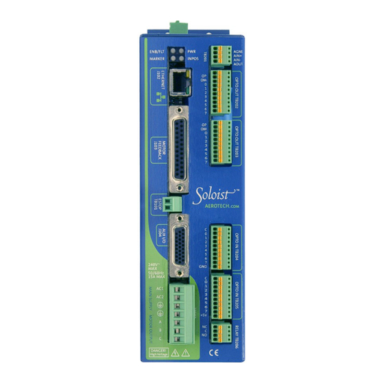
Electrical Specifications ..........1.6 Physical Dimensions ..........1.8 Environmental Specifications ........1.9 Chapter Overview Use this chapter to become familiar with the features on your Soloist™. This chapter includes electrical, mechanical, and environmental specifications. Figure 1-1 Both Versions of the Soloist... -
Page 12: Feature Summary
Introduction Soloist Hardware Manual Feature Summary Review the following summary of the standard and optional features of the Soloist. 1.2.1 Power Amplifier Configure for brush, brushless, and stepper motor operation Standard 100 VDC – 320 VDC, optional 10 VDC – 320 VDC bus operation ... -
Page 13: Soloist Connections
Soloist Hardware Manual Introduction Soloist Connections The Soloist AC power, motor power, feedback, and communications connections are detailed in Figure 1-2. Figure 1-2 Soloist Hardware www.aerotech.com... -
Page 14: Soloist Power Features
Soloist Hardware Manual Soloist Power Features If you purchased the Soloist with the standard set of features, it includes the bus power supply that operates from 70-240 VAC (100 – 340 VDC). The power supply provides off-line operation without the need for an isolation transformer. A soft start circuit is included to prevent high inrush currents. -
Page 15: Soloist Voltage Configurations
Soloist Hardware Manual Introduction Soloist Voltage Configurations The Soloist is available in three models with continuous power, ranging from 1,100 to 2,300 watts. The available voltage configurations and power options for these models are shown in Table 1-1. Table 1-1... -
Page 16: Electrical Specifications
Introduction Soloist Hardware Manual Electrical Specifications The electrical specifications for the Soloist are listed in Table 1-2. Table 1-2 Electrical Specifications Description Units Soloist10 Soloist20 Soloist30 Main Supply 70 - 240 VAC Input Volts -AUXPWR Input Frequency Main Supply 50-60... - Page 17 Soloist Hardware Manual Introduction Table 1-2 Electrical Specifications Feature Description - Brush (torque mode) Modes of Operation - Brushless - Stepper Hall A-Pin 10, Hall B-Pin 5, Hall C-Pin 11: Hall effect device inputs for commutation, 0 to 5 VDC, internal pull-up, 10K input.
-
Page 18: Physical Dimensions
Introduction Soloist Hardware Manual Physical Dimensions The physical dimensions for the Soloist are shown in Figure 1-4. Separate Soloist’s from each other and provide 25 mm (1 inch) of free air space. 65.7 [2.59] 63.5 [2.50] 63.5 [2.50] Each unit should be surrounded by 15.9 [0.63]... -
Page 19: Environmental Specifications
Soloist Hardware Manual Introduction Environmental Specifications The environmental specifications for the Soloist are listed in the following table. Temperature: Ambient Operating: 5" - 50" C (41" - 122" F) " " Storage: -20 - 70 C (-4 - 158 Humidity: Maximum relative humidity is 80% for temperatures up to 31"... - Page 20 Introduction Soloist Hardware Manual 1-10 www.aerotech.com...
- Page 21 Emergency Stop Sense Input (TB101)......2-10 Motor Connections............2-12 Communication Channel Settings ........2-22 Soloist Help Information........... 2-24 Introduction This chapter describes hardware configurations, including switches, jumpers, connectors, and power connections used with a brush, brushless, or stepper motors. Wiring, grounding, shielding techniques, and motor phasing are also described.
-
Page 22: Installation And Configuration
Installation and Configuration Soloist Hardware Manual Safety Procedures and Warnings The following statements define the Warning and Danger symbols that appear in this manual. If you fail to observe these precautions, serious personal injury or damage to the equipment results. -
Page 23: Motor And Ac Power Connections
External fuses or circuit breakers (15 Amps maximum, time delay type) are required for the AC1 and AC2 AC inputs for protection and must be located near the Soloist. For optimum protection, use 10 Amp protection devices (15 Amp devices are required in applications requiring maximum power). -
Page 24: Wiring, Grounding, And Shielding Techniques
Installation and Configuration Soloist Hardware Manual Wiring, Grounding, and Shielding Techniques To reduce electrical noise in the Soloist, follow the motor and input power wiring techniques explained in the following section. 2.4.1 Minimizing EMI Interference " Use shielded cable to carry the motor current and tie the shield to earth ground. -
Page 25: Auxpwr (Auxiliary Power) Option
The -AUXPWR option provides keep alive power for the Soloist to remain operational when motor power is removed (for example, when an external emergency stop circuit is required, as illustrated in Section 2.6.1 This option also allows the Soloist to operate at bus voltages less than 120 VDC (85 VAC). -
Page 26: Typical Ac Wiring With The -Auxpwr Option And An External Transformer
Typical AC Wiring with the -AUXPWR Option and an External Transformer To generate a 40, 80 160 VDC Bus for the motor power, connect your Soloist to a 115/230 VAC source. The following three figures illustrate the six combinations available for both AC input voltages and all three DC bus voltages when the -AUXPWR option is used. -
Page 27: Figure 2-3 80 Volt Dc Bus From 115 And 230 Vac Source
Soloist Hardware Manual Installation and Configuration Soloist PRIMARY FUSE 4A SLO-BLO AUXPWR OPTION #18 WHT TRANSFORMER AC HI INTERNAL 115VAC THERMAL splice AC LO 50/60 HZ SWITCH #18 WHT INPUT RED 56v 115v BLK SAFTEY 100v ORN GRN 0v NOTES: 0v GRAY 1. - Page 28 Installation and Configuration Soloist Hardware Manual NOTES: Soloist PRIMARY FUSE 1. THE AUXPWR OPTION IS USED WHEN THE MAIN SUPPLY POWER IS BELOW 4A SLO-BLO AUXPWR OPTION #18 WHT 100VAC. TYPICALLY 28-56VAC INPUT. THIS COREESPONDS TO A BUS TRANSFORMER AC HI INTERNAL VOLTAGE OF 40-80VDC.
-
Page 29: Minimizing 50/60 Hz Line Interference
Ground Protective TB102 Ground This configuration is especially important if the Soloist is operating at DC bus voltages of 100 VDC or 340 VDC (e.g., 115 VAC to 230 VAC input power). Figure 2-5 Back-Propagation Line Filter Connection 2.5.2 I/O and Signal Wiring Requirements The I/O, communication, and encoder feedback connections are low power connections. -
Page 30: Emergency Stop Sense Input (Tb101)
JP6 as shown in the following table. Using a higher input voltage requires adding an external series resistor to limit the current. If the ESTOP bit is enabled in the FaultMaskGlobal axis parameter (see the Soloist Help), the ESTOP input must be driven to prevent the ESTOP fault condition. -
Page 31: Typical Estop Interface
Installation and Configuration 2.6.1 Typical ESTOP Interface By connecting an emergency stop circuit to the Soloist, you disable power to the motor by removing power to the power stage of the drive while maintaining power to the control section (Figure 2-7). This is accomplished by the use of an external relay (CR1. The ESTOP sense input (TB101) notifies you of the setting of the ESTOP fault. -
Page 32: Motor Connections
2.7.1 DC Brush Motor Connections in Torque Mode When you connect a DC brush motor in torque mode, use the configuration shown in Figure 2-8. Note: No connection is made to the Soloist ØB terminal, as shown in Figure Clockwise 2-8. -
Page 33: Brushless Motor Connections
When you connect a brushless motor that is an Aerotech motor with Aerotech cabling, no motor phasing process is required. If you are using an Aerotech brushless motor with the Soloist, see the system interconnection drawing in Figure 2-9 to determine the motor phase and Hall connections. -
Page 34: Brushless Motor Phasing
Installation and Configuration Soloist Hardware Manual 2.7.2.1 Brushless Motor Phasing When configuring the Soloist to run a non-Aerotech brushless motor, the motor leads (A, Clockwise (CW) B, and C on TB102) must be correctly connected for proper operation. (Positive Direction) -
Page 35: Brushless Motor Hall Effect Feedback Connections
12. A value of 0 for the given Hall input indicates zero voltage or logic low and a value of Motor Shaft 1 indicates five volts or logic high. You can view these logic levels in the Soloist HMI in the Axis I/O section of the Diagnostic panel of the screen, as shown in Figure 2-11. -
Page 36: Hall Effect Phasing
Soloist Hardware Manual 2.7.2.3 Hall Effect Phasing For an AC brushless motor with an unknown Hall sequence, one of two methods can be CW Rotation used to determine the proper motor connections to the Soloist. (Positive Direction) Motor Shaft ... -
Page 37: Figure 2-12 Motor Phasing
Soloist Hardware Manual Installation and Configuration Test Setup Brushless Motor 10K OHM Power Supply 10K OHM Clockwise Rotation or Plus Motion 0 120 180 360 6O 240 Hall A Hall B Hall C ØC ØB ØA ØC ØB +20V Motor... -
Page 38: Stepper Motor Connections
PosScaleFactor parameter. To correct the phasing, reverse the connections to the A and B terminals on the Soloist. This is important because the inputs for the end of travel (EOT) limit are determined by motor rotation. After correctly phasing the motor, you can reverse the motor direction when commanding a positive move from a user task by changing the PosScaleFactor parameter to a negative value. -
Page 39: Encoder Feedback Connections
The same encoder feedback device is used for brush and brushless motor types. Each of the encoder channels in the Soloist accepts a differential line driver encoder. DC Brush and brushless motors may have a separate position and a velocity feedback device. Use an... -
Page 40: Encoder Phasing
Soloist HMI, as shown in Figure 2-16. The program causes the encoder to produce a more positive position. If it counts negative, swap the connections to the controllers SIN and... -
Page 41: End Of Travel Limit Connections
If the EOT limits are reversed, swap the connections to the CW and CCW inputs at the Soloist J103 connector. View the EOT limit inputs in the Soloist HMI in the Diagnostic panel’s Axis I/O section, as shown in Figure 2-17. -
Page 42: Communication Channel Settings
2.10 Communication Channel Settings You must assign a unique device number (the drive number) to each Soloist in your system, which is determined by the communication connection to the Soloist HMI or library interface. If a USB communication connection is used, the drive number is assigned with the S1 switch located on the side of the Soloist. -
Page 43: Table 2-6 Soloist Switch Settings (S1)
Soloist Hardware Manual Installation and Configuration Table 2-6 Soloist Switch Settings (S1) Switch Settings * Soloist # Switches 9 - 5 ** 10th 11th 12th 13th 14th 15th 16th 17th 18th 19th 20th 21st 22nd 23rd 24th 25th 26th 27th... -
Page 44: Soloist Help Information
2.11 Soloist Help Information For additional information about the Soloist and PC configuration, hardware requirements, programming, utilities and system operation, and the Soloist HMI application, see the “ Getting Started” topic in the Soloist Help. # # # 2-24 www.aerotech.com... -
Page 45: Technical Details
Brake / Relay Interface (J103, TB103) ......3-18 RS-232 Serial Port (TB103) ..........3-19 USB Port (J101)*.............. 3-20 * Planned Option, Consult Aerotech Inc. for availability 3.1. Port 0 I/O and the Secondary Encoder Channel (J104) The J104 connector provides six user inputs and four outputs as well as a secondary line driver encoder interface. -
Page 46: Chapter 3: Technical Details
Technical Details Soloist Hardware Manual A re-settable fuse protects the external power provided by the Soloist to the user. Should an over-current condition occur, the fusing device would open to protect against the overload. To reset the device, remove the overload condition. -
Page 47: Secondary Encoder Channel (J104)
Soloist Hardware Manual Technical Details 3.1.1. Secondary Encoder Channel (J104) This encoder channel may be used as an input for master/slave operation (handwheel) or for dual loop systems. This encoder must be a 5-volt RS-422 line driver encoder. It allows up to an 8 MHz encoder signal (31 nanosecond minimum edge separation), producing 32 million counts per second, after times four (x4) quadrature decoding. -
Page 48: Figure 3-2. Primary / Secondary Encoder Channels (J103, J104)
Technical Details Soloist Hardware Manual Figure 3-2. Primary / Secondary Encoder Channels (J103, J104) www.aerotech.com... -
Page 49: Port 0 User Digital Outputs (J104)
Soloist Hardware Manual Technical Details 3.1.2. Port 0 User Digital Outputs (J104) The digital outputs (see Figure 3-3) are software configurable by the DriveIOConfig axis parameter as sourcing or sinking and are driven by a PS2802-4 opto-isolator. See Table 3-4 for the pin numbers and Table 3-5 for the PS2802-4 device specifications. See Figure 3-4 and Figure 3-5 for user connections to the outputs in current sourcing and current sinking modes. -
Page 50: Figure 3-3. User Outputs (J104)
Technical Details Soloist Hardware Manual Figure 3-3. User Outputs (J104) www.aerotech.com... -
Page 51: Figure 3-4. Outputs Connected As Current Sinking
Soloist Hardware Manual Technical Details Figure 3-4. Outputs Connected as Current Sinking Be sure to set the DriveIOConfig axis parameter, to configure the outputs as current sinking or current sourcing! All outputs on a port (0, 1 or 2), must be connected as all sourcing, or all sinking outputs. -
Page 52: Port 0 User Digital Inputs (J104)
Technical Details Soloist Hardware Manual 3.1.3. Port 0 User Digital Inputs (J104) The high-speed inputs 12 and 13 (Figure 3-8), are scaled for a 5 volt input voltage. Using a higher input voltage requires adding external series resistors to limit the current to 20 milliamps. -
Page 53: Figure 3-6. Connecting Current Sinking Inputs
Soloist Hardware Manual Technical Details Figure 3-6. Connecting Current Sinking Inputs Figure 3-7. Connecting Current Sourcing Inputs www.aerotech.com... -
Page 54: Figure 3-8. Low Speed And High Speed User Inputs (J104)
Technical Details Soloist Hardware Manual Figure 3-8. Low Speed and High Speed User Inputs (J104) 3-10 www.aerotech.com... -
Page 55: User Analog Output 0 (J104)
Soloist Hardware Manual Technical Details 3.1.4. User Analog Output 0 (J104) Analog output 0 is driven by a 16-bit DAC8531 digital to analog converter and buffered by TL082 op-amps, producing a single-ended output voltage in the range of +/- 10 volts. -
Page 56: User Analog Input 0 (J104)
Technical Details Soloist Hardware Manual 3.1.5. User Analog Input 0 (J104) Analog input 0 is differential, buffered by a TL082 op-amp and converted to digital by 12-bit ADS7816 analog to digital converter allowing an input voltage in the range of +/- 10 volts. -
Page 57: Position Synchronized Output (Pso)
The Soloist provides only single-axis tracking of one of the two encoder input channel. Encoder signals may come from the primary or secondary encoder channels. - Page 58 Data Update mode allows analog or digital outputs to be set by the same trigger. The capture and update modes are defined in Figure 3-12. For a full description of these modes, refer to the Soloist HMI help. PSO Output...
-
Page 59: Motor Feedback (J103)
(x 4) quadrature decoding. See Figure 3-2 for typical input circuitry of the encoder signals. The Soloist standardly accepts a line driver encoder, or with the – MXU option, an analog sine wave encoder (see Section 3.3.1). See Section 2.8.1. -
Page 60: Figure 3-13. Limit, Thermistor And Hall-Effect Inputs (J103)
* Total user +5 V power is limited to 500 mA, by an internal re-settable fuse. All external power provided by the Soloist to the user is protected by a re-settable fuse. Should an over-current condition occur, the fusing device would open to provide protection against the overload. -
Page 61: Mxu Option
CfgFbkEncSineGain, CfgFbkEncSineOffset, CfgFbkEncMultFactorMXU axis parameters. This can be done automatically using the “ Encoder Feedback Configuration” utility. See the Soloist HMI help for more information. The – MXU option is not compatible with PSO firing capabilities because it does not generate a serial pulse stream as required by the PSO (Position Synchronized Output) option. -
Page 62: Brake / Relay Interface (J103, Tb103)
The design also allows the brake to be powered through the existing encoder feedback cable without the need for additional wiring, as indicated in Figure 3-15. Failsafe brakes used by Aerotech require a 24 VDC supply capable of supplying 1 ampere of current. -
Page 63: Serial Port (Tb103)
Soloist Hardware Manual Technical Details 3.4. RS-232 Serial Port (TB103) The RS-232C port is shown in Figure 3-16. Connecting the RS-232 port to a user’s PC requires only a standard 9-pin cable (not a null modem). Table 3-14. TB103 RS-232 Connector Pin-out... -
Page 64: Usb Port (J101)
Soloist Hardware Manual 3.5. USB Port (J101)* The USB port has all of the same functionality as the Ethernet interface for Aerotech’s utilities. The Ethernet port however, does have some additional features for non-Aerotech devices. * Planned Feature, Consult Aerotech Inc. for availability. -
Page 65: Table 4-1. Soloist Options
Port 1 and Port 2 Opto-Isolated Outputs (TB202, TB203) ...4-4 Port 1 and Port 2 Opto-Isolated Inputs (TB204, TB205)..4-6 User Power (TB204, TB205)..........4-9 Brake / Relay (TB206)............4-9 4.1. Introduction The following options are available for the Soloist. Table 4-1. Soloist Options Option Capabilities – AUXPWR Separate control power input for the 20-80VDC bus as described in Chapter 2, section 2.4.2. -
Page 66: Chapter 4: Soloist Options
Soloist Options Soloist Hardware Manual 4.2. -IO Option Board See the following sections for details on the connector Pin-out and technical information for the -IO options. – IO Option Board (690D1611 Rev. 0) Figure 4-1. 4.2.1. Analog Input 1 (TB201) -
Page 67: Analog Output 1 (Tb201)
Soloist Hardware Manual Soloist Options 4.2.2. Analog Output 1 (TB201) Analog output 1 is driven by a 16-bit DAC8531 digital to analog converter and buffered by a TL084 op-amp, producing a single-ended output voltage in the range of +/- 10 volts. -
Page 68: Port 1 And Port 2 Opto-Isolated Outputs (Tb202, Tb203)
Soloist Options Soloist Hardware Manual 4.2.3. Port 1 and Port 2 Opto-Isolated Outputs (TB202, TB203) The digital outputs are software configurable by the DriveIOConfig axis parameter as sourcing or sinking. All outputs must all be connected as sourcing, or all as sinking. The outputs are driven by PS2802-4 opto-isolators that are rated for 40 volts maximum and up to 80 mA/channel, not to exceed 90 mW per channel. -
Page 69: Figure 4-4. Connecting Outputs In Current Sinking Mode
Soloist Hardware Manual Soloist Options Figure 4-4. Connecting Outputs in Current Sinking Mode Be sure to set the DriveIOConfig axis parameter, to configure the outputs as current sinking or current sourcing ! All outputs on a single port (0, 1 or 2) must be connected as all sourcing, or as all sinking outputs. -
Page 70: Port 1 And Port 2 Opto-Isolated Inputs (Tb204, Tb205)
Soloist Options Soloist Hardware Manual Suppression diodes must be installed on outputs that are used to drive relays or other inductive devices to protect the output devices from being damaged by the inductive spikes that occur when the device is turned off. Suppressor diodes can be installed on all outputs to provide greater protection. -
Page 71: Table 4-10. Table
Soloist Hardware Manual Soloist Options Table 4-8. Port 2 Opto-Isolated Input Connector Pin-out (TB205) Pin # Label Description In/Out/Bi Input Common for inputs 0-7 (TB205) Input Input 0 (Optically-Isolated) – See pin 1 Input 0 Input Input 1 (Optically-Isolated) – See pin 1... -
Page 72: Figure 4-7. Inputs Connected In Current Sinking Mode
Soloist Options Soloist Hardware Manual Figure 4-7. Inputs Connected in Current Sinking Mode www.aerotech.com... -
Page 73: User Power (Tb204, Tb205)
Description In/Out/Bi User Common (for user +5 VDC power) Pin 10 of TB205 provides +5 VDC power to the user from the Soloist’s internal power supply, which may be used to power external devices (3 Amps maximum). Table 4-10. +5 Volt Power Connector Pin out (TB205) -
Page 74: Brake Configuration Jumpers
Soloist Options Soloist Hardware Manual 4.2.6.1. Brake Configuration Jumpers The configuration of JP1, as shown in the table above allows either the Brake + or the Brake - output to be switched by the relay and connected at the J103 motor feedback connector, or for the brake to be connected at TB206. -
Page 75: Figure 4-8. Brake Connected To Tb206
Soloist Hardware Manual Soloist Options Figure 4-8. Brake Connected to TB206 Figure 4-9 is an example of a +24 VDC Brake connected to J103, the Motor Feedback connector. In this example the external +24 power source is connected to TB206. Also note that JP1 is set 1-2 and 3-4, with all others removed. - Page 76 Soloist Options Soloist Hardware Manual Step #3 Suppression and Snubber requirements Due to the inductive effects of the load (brake) suppression and/or snubber, components are needed to reduce arching and prevent damage to the Brake Relay contacts. Suppression can also reduce the electrical noise that is emitted when a circuit is turned off.
-
Page 77: Figure 4-10. Suppression For Dc Brake Systems
Soloist Hardware Manual Soloist Options Figure 4-10. Suppression for DC Brake Systems www.aerotech.com 4-13... - Page 78 Soloist Options Soloist Hardware Manual " " " 4-14 www.aerotech.com...
-
Page 79: Chapter 5: Accessories
The following three tables show a summary of the standard cables used for interconnecting various items to the Soloist. The “ -xx” , in the tables below, is used to specify the length in decimeters; “ -yy” specifies the length in feet. -
Page 80: Table 5-2. Combined Motor & Feedback Cables
Accessories Soloist Hardware Manual Table 5-2. Combined Motor & Feedback Cables Soloist Part Number (s) Description Stage/Motor BL MTR & FB-25DU FL-25DU- C18982-xx* MAX107DM BFMCDNT-yy* Obsolete Used On: Any brushless motor stage having a single 25 pin “ D” style Motor Output connector for motor power, encoder, limits and halls. -
Page 81: Table 5-3. Individual Motor Cables
Soloist Hardware Manual Accessories Table 5-3. Individual Motor Cables Soloist Part Number (s) Description Stage/Motor C15805-xx* BL MTR-FL-4MS-MAX450DM PMCNT-yy* Obsolete Used On: Any brushless motor stage having a 4 pin “ MS” style connector for motor power. Motor Output BM/BMS motors (with -MS option) -
Page 82: Table 5-4. Individual Feedback Cables
Accessories Soloist Hardware Manual Table 5-4. Individual Feedback Cables Part Number (s) Description Soloist Stage/Motor C16501-xx* BL FB-25DU-25DU-MAX120DM C16505-xx* BL FB-25DU-25DU-MAX240DM BFCMX-yy * Obsolete Used On: Any brushless motor stage having a 25 pin “ D” style connector for encoder, limits, halls and brake. -
Page 83: Joystick Interface
The user may connect an Aerotech JI (not JBV, or JP4) joystick or their own joystick and switches to the Soloist (Refer to Figure 5-1). The joystick interlock input in the logic low state may be used to detect the presence of the joystick. - Page 84 Accessories Soloist Hardware Manual A standard Aerotech JI joystick may be connected to J104 of the Soloist as a single axis joystick through the following cable, shown below (Figure 5-2 and Figure 5-3). Figure 5-2 indicates the required cable and Figure 5-3 indicates the interconnection of the joystick to the Soloist.
-
Page 85: Handwheel Interface
The user may connect a handwheel or any device producing differential quadrature signals for manual positioning of the axes. See the Soloist Help for information on the Gear command to enable the handwheel. The handwheel may be connected to J104 of the Soloist as shown in Figure 5-4, below. - Page 86 Accessories Soloist Hardware Manual 10 FT. OR AR. LENGTH 1. INSTALL LABEL TO BACK OF HANDWHEEL Soloist J104 HANDWHEEL BBA32 MODEL: HWA32-FLY-XX XX = CABLE LENGTH IN DECIMETERS 630B1983-1 REV. - SUMTAK S/N: XXXXXX XXXXXX = WORK ORDER NUMBER LGF-043-100...
-
Page 87: Figure 5-6. Bba32 Interface Used To Connect A Handwheel With Flying Leads (No Connector)
Soloist Hardware Manual Accessories NOTES: Soloist THE BBA32 CONSISTS OF THE FOLLOWING PARTS: BBA32 AUX I/O INTERFACE 1 - ECZ01230 (PHOENIX BREAK-OUT MODULE) 1 - ECZ01231 (26 PIN HD M/F CABLE 2.5FT.) 26 PIN HD J104 M/F CABLE ECZ01231 2.5FT. - Page 88 Accessories Soloist Hardware Manual " " " 5-10 www.aerotech.com...
-
Page 89: Chapter 6: Troubleshooting
Table 6-1 lists the most common symptoms of irregular operation and the possible causes and solutions for these faults. More information can be found in the Soloist HMI help. Before performing the tests described in Table 6-1, be aware of lethal voltages inside the controller and at the input and output power connections. -
Page 90: Table 6-1. Amplifier Faults, Causes, And Solutions
Troubleshooting Soloist Hardware Manual Table 6-1. Amplifier Faults, Causes, and Solutions Symptom Possible Cause and Solution Encoder (sine and cosine) signals are improperly Motor rotates connected. See Section 2.8. for motor phasing uncontrollably information. Brushless motor will not Motor phases A, B, and C connected incorrectly relative rotate. -
Page 91: Soloist Test Points
Troubleshooting 6.2. Soloist Test Points The following test points are available internally to the Soloist, refer to Section 6.4. for their locations. All test points not shown are for Aerotech internal use only. Table 6-2. Soloist Control Board Test Points... -
Page 92: Fuse Replacement
Soloist Hardware Manual 6.3. Fuse Replacement Table 6-4 lists the manufacturer and Aerotech’s part number for typical replacement fuses. Additional fuse information can be found on the system drawing supplied with the unit. See Section 6.4. for fuse location information. -
Page 93: Soloist Board Assembly
6.4. Soloist Board Assembly Figure 6-1 highlights the important components located on the control board. The Soloist has a few jumper selectable items, none of which normally need to be changed by the user, since all of the important configurable items are software selectable. Table 6-6 lists the jumpers and the default configurations for the Soloist board. - Page 94 Troubleshooting Soloist Hardware Manual Table 6-6. Soloist Jumper Selections Jumpers Positions Function 1-2 * No Shunt Option Present (Standard, Soloist10, 20) Shunt Option Present (Optional, except Soloist30) 1-2 * Watch dog enabled (Standard) Watch dog disabled 1-2 * 24 Volt Emergency Stop (Standard)
-
Page 95: Preventative Maintenance
6.5.1. Cleaning The Soloist chassis can be wiped with a clean, dry, soft cloth. The cloth may be slightly moistened if required with water or isopropyl alcohol to aid in cleaning if necessary. In this case, be careful not to allow moisture to enter the Soloist or onto exposed connectors/components. - Page 96 Troubleshooting Soloist Hardware Manual " " " www.aerotech.com...
-
Page 97: Appendix A: Glossary Of Terms
Soloist Hardware Manual Glossary of Terms APPENDIX A: GLOSSARY OF TERMS In This Section: Glossary .............A-1 The positioning error resulting from angular motion and Abbe Error an offset between the measuring device and the point of interest. Abbe Offset The value of the offset between the measuring device and the point of interest. - Page 98 Glossary of Terms Soloist Hardware Manual Ball Screw A precision device for translating rotary motion into linear motion. A lead screw is a low-cost lower performance device performing the same function. Unit consists of an externally threaded screw and an internally threaded ball nut.
- Page 99 0 electrical degrees. This method is slightly more difficult to implement than standard 6-step, but more closely approximates the motor’s back emf. The result is smoother control and less ripple. Aerotech’s BA series self-commutate using this method. Commutation, Sinusoidal The process of switching motor phase current based on motor position information, usually from an encoder.
- Page 100 Glossary of Terms Soloist Hardware Manual Cycle When motion is repeated (move and dwell) such as repetitive back-and-forth motion. DC Brushless Servo A servomotor with stationary windings in the stator assembly and permanent magnet rotor. (See AC Brushless Servo) Deceleration The change in velocity as a function of time.
- Page 101 Soloist Hardware Manual Glossary of Terms G.P.I.B. A standard protocol, analogous to RS-232, for transmitting digital information. The G.P.I.B. interface (IEEE-488) transmits data in parallel instead of serial format. (See IEEE-488) Gain Comparison or ratio of the output signal and the input signal.
- Page 102 Glossary of Terms Soloist Hardware Manual Life The minimum rated lifetime of a stage at maximum payload while maintaining positioning specifications. Limit Switch A sensor used to determine the end of travel on a linear motion assembly. Limits Sensors called limits that alert the control electronics that the physical end of travel is being approached and motion should stop.
- Page 103 (Proportional Integral Derivative) used in compensation of a closed-loop system. The terms are optimally adjusted to have the output response equal the input command. Aerotech controllers utilize the more sophisticated PID FVFA loop which incorporates additional terms for greater system performance.
- Page 104 Glossary of Terms Soloist Hardware Manual Range The maximum allowable travel of a positioning stage. Resolver to Digital Converter. Electronic component that converts the analog signals from a resolver (transmitter type) into a digital word representing angular position. The maximum deviation from the mean (each side) when Repeatability repeatedly approaching a position.
- Page 105 Soloist Hardware Manual Glossary of Terms Settling Time Time required for a motion system to cease motion once the command for motion has ended. Shaft Radial Load Maximum radial load that can be applied to the end of the motor shaft at maximum motor speed.
- Page 106 Glossary of Terms Soloist Hardware Manual Wobble An irregular, non-repeatable rocking or staggering motion of the table top of a rotary stage. Wobble is defined as an angular error between the actual axis of rotation and the theoretical axis of rotation.
- Page 107 Aerotech makes no warranty that its products are fit for the use or purpose to which they may be put by the buyer, where or not such use or purpose has been disclosed...
-
Page 108: Appendix B: Warranty And Field Service
Soloist Hardware Manual Returned Product Non- After Aerotech's examination, the buyer shall be notified of the repair cost. At such time, warranty Determination the buyer must issue a valid purchase order to cover the cost of the repair and freight, or authorize the product(s) to be shipped back as is, at the buyer's expense. -
Page 109: Appendix C: Technical Changes
Soloist Hardware Manual Technical Changes APPENDIX C: TECHNICAL CHANGES In This Section: Current Changes..............C-1 Archive of Changes..............C-2 C.1. Current Changes Table C-1. Current Changes Version Section(s) Affected General Information Corrected Input and Output power Specifications in 1.6. - Page 110 Technical Changes Soloist Hardware Manual C.2. Archive of Changes Version Section(s) Affected General Information All New First release of the manual. Formatting changes, non-technical. Digital I/O renumbered from 0-n, to Port 0, 0-7, Port Chap. 3, 4 1, 0-7 and Port 2, 0-7. Chap. 4 Picture updated.
-
Page 111: Index
Soloist Hardware Manual Index INDEX RS-232/RS-422, 3-19 Continuous Output Current, 1-5 Control Board, 6-5 Assembly, 6-5 < 85 VAC AC Bus Input Power, 2-3 Jumpers, 6-5, 6-6 40/80 VDC Power Transformer, 2-5 DC Brush Motor Configuration, 2-12 AC Power Connections, 2-3... - Page 112 Index Soloist Hardware Manual AC1, AC2, 2-3 Connector, 4-10 Main Supply, 2-3 Motor Feedback Connector Location, 1-3 Motor Frame Connections, 2-3 Motor Frame Connection, 2-3 Shield Connection, 2-3 Motor Output Terminals Three-Phase Power Input, 2-3 A, B, and C, 2-3...
- Page 113 Soloist Hardware Manual Index TB4, 4-2 TB7, 4-6 Test Points, 6-3 -S, 1-5 -S Option, 4-1 Three-Phase Motor Terminal Connections, 2-3 Safety Procedures, 2-2 Three-Phase Power Input (optional), 2-3 Troubleshooting, 6-1 Shield Connection, 2-3 Shielding Techniques, 2-4 TV0.3-28 power transformer (optional), 2-5 Signal Wiring Requirements, 2-9 TV0.3-56 power transformer (optional), 2-5...
- Page 114 Index Soloist Hardware Manual www.aerotech.com...
- Page 115 READER’S COMMENTS AEROTECH Soloist User’s Manual P/N EDU180, April 2005 Please answer the questions below and add any suggestions for improving this document. Is the information: Adequate to the subject? ____ ____ Well organized? ____ ____ Clearly presented? ____ ____...
- Page 117 Automation Aerotech’s Soloist™ is a single-axis servo controller that combines a power supply, amplifier, Solutions for Engineering and position controller in a single package. The Soloist can control up to four tasks Reference Electronic simultaneously, as well as handle variables...
- Page 118 Automation Solutions for Laser Engineered System Processing, Aerotech has over 30 years of experience manufacturing turnkey and complete motion Medical Device subsystems for some of the largest companies in the world. Our engineers and technicians Manufacturing, and Life have developed an array of systems for...
Need help?
Do you have a question about the SOLOIST and is the answer not in the manual?
Questions and answers