Table of Contents
Advertisement
Quick Links
Download this manual
See also:
Manual
Advertisement
Table of Contents

Related Manuals for GRAUPNER S1005


Summary of Contents for GRAUPNER S1005
- Page 1 S1005/S1006.mz-18/24 HoTT.2.en WARNING Programming manual CHOKING HAZARD Sma l parts Not for ch ld en under 3 years For age 3 and up...
-
Page 2: Table Of Contents
Table of contents Restoring the transmitter software ....... 30 Wireless HoTT system ........... 111 General instructions Starting up the receiver ........... 32 Telemetry ..............114 Before use ..............3 Receiver firmware updates ........33 Introduction ..............3 Fixed-wing models Backing up the receiver settings ......33 Warning and advisory symbols and their meaning .. -
Page 3: Before Use
Programming example Before use Warning and advisory symbols and their meaning We are glad that you have chosen a Graupner mz-18 Sequencer ..............218 WARNING: HoTT or mz-24 HoTT 2.4 GHz remote control system. This symbol indicates subsequent information This system is extremely versatile and can be used by Appendix that is essential for the user to observe. -
Page 4: Safety Instructions
Only use the components and recommended spare This operating manual is considered part of parts. Always use matching, original Graupner plug-in the product. It contains important instructions Installing the receiver antennas on how to operate and handle your remote connectors of the same design and material. - Page 5 diversity antennas (two antennas), the active end of the throttle control stick is at stop/idle. personal injury. second antenna should be at a 90° angle from the end Always switch on the transmitter before the receiver. Operating models: Airplane, helicopter, ship and of the first antenna, and the distance between the active automobile Always switch off the receiver before...
- Page 6 Additional details on noise filters can be found in the • To satisfy the high-frequency transmission explosion hazard exists. main Graupner FS catalogue or on the Internet at www. requirements of the FCC for mobile trans- graupner.de. All batteries must be charged before each use. To...
- Page 7 Graupner|SJ GmbH directly involved in the event leading to the loss. This does not apply in the event of unlimited liability on the part of Graupner|SJ GmbH due to intent or gross negligence according to binding law. Furthermore, only those claims can be reimbursed which are supported by a log file (see "Collecting/saving data"...
-
Page 8: Nickel Metal Hydride Rechargeable Batteries
The cell voltage should not fall below 1.2 V All of the batteries that are sold by Graupner and GM- • If the battery heats up above 60°C while it is being when stored for a long time. - Page 9 programs unnecessarily shorten the life of batteries and are only suitable for checking the battery quality or restoring old cells. It is likewise not recommendable to charge and discharge a battery before a single use unless you want to check the battery's quality.
-
Page 10: Lithium-Ion And Lithium Polymer Rechargeable Batteries
Before each use, make sure that the batteries are in by more than 0.05 V, or if the differences in voltage Graupner, see page 16 or listed at www.graupner. a satisfactory condition. Defective or damaged cells are monitored and equalized by a balancer connec- or batteries may not be used. - Page 11 This • A continuous current of approximately 1 C holds true particularly for the plus connector. The does not pose a problem for Graupner connectors can easily break. lithium-ion/lithium polymer batteries. If the Cell connector...
-
Page 12: Disposal Of Used Single-Use And Rechargeable Batteries
Graupner|SJ GmbH Any batteries (including rechargeable batteries) must be Service: Used batteries removed from the device and disposed of separately at Henriettenstrasse 96 an appropriate collection point. -
Page 13: And Mz-24
Computer systems for the mz-18 and mz-24 series two remote control sets with a 2.4 GHz Graupner HoTT system (hopping telemetry transmission) mz-18 remote control set, order No. S1005 mz-24 remote control set, order No. S1006 Common features • Microcomputer remote control system using the •... -
Page 14: Technical Data
Modulation FHSS For additional accessories, see the Annex or the 9 functions of which 4 can be Internet at www.graupner.de You can also contact your Antenna 1 x approx. 145 mm long, trimmed dealer. He would be glad to assist you. -
Page 15: Transmitter Power Supply
For rechargeable NiMH battery with 2000 mAh capacity, and been set in the submenu "Etc.Set" of the this reason, you should only use original Graupner the mz-24 HoTT transmitter comes standard with a system menu, page 202! charging cables with order No. -
Page 16: Recommended Chargers (Accessories)
Other chargers as well as details on the listed chargers can be pulling the supply cable. Then lift the battery and pull it NORMAL found in the main Graupner FS catalogue or on the Internet at MODEL NAME 1 gently off of the velcro. -
Page 17: Adjusting The Control Sticks
General charging instructions Adjusting the control sticks • 3 and 6 To change the standard setting of the left and right • Follow the charging instructions of the Both the left and right control sticks can optionally be control sticks, turn the screw toward the inside of the charger manufacturer and battery set from neutralizing to non-neutralizing and vice versa. -
Page 18: Control Elements On The Mz-24 Hott Transmitter
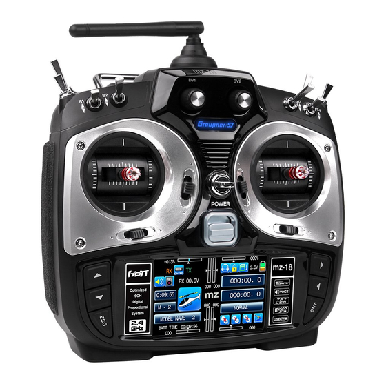
Transmitter description Front side Control elements on the mz-24 HoTT transmitter Rotatable and foldable antenna proportional dial DV3 proportional dial DV2 proportional dial DV4 proportional dial DV1 Switch SW 8 Switch SW 6 Switch SW 5 Switch SW 7 Switch SW 4 Switch SW 1 Switch SW 3 Switch SW 2... -
Page 19: Button Lock
Button lock Buttons as well as ESC and Digital trim With an optical and acoustic display Although the two mz-18 HoTT and mz-24 HoTT Access to adjustments can be blocked in the basic The two control sticks come with digital trim. Briefly transmitter display by simultaneously pressing the transmitters are primarily operated by touching the touch the trim switch to move the neutral position of the... -
Page 20: Display
Display Graphic display of the position of the standard, left INC/DEC button DT 1 with a numeric position and direction display that only comes with the mz-24 HoTT transmitter. Graphic display of the position of the standard, right INC/DEC button DT 2 with a numeric position and direction display that only comes with the mz-24 HoTT transmitter. -
Page 21: Operating The Displays
Operating the displays The display is basically operated by touching the identified with"B", "F", and "S", special selection menus The pink SYSTEM menu that can be opened by desired field with a finger or the provided stylus: open on the bottom right from which you can switch to pressing "S"... -
Page 22: Warnings
Warnings Depending on the context, different warning windows "acute warning" display BACK MODEL NAME 1 appear in the display for the mz-18 HoTT transmitter You can open this display by touching mz in the middle and the mz-24 HoTT transmitter. These can be divided of the transmitter's basic display: into two groups: BIND ON/OFF... - Page 23 At the same time, the display contrast is reduced to 05 to save power. This warning can be kept from reappearing by touching button at the top right then deleted by touching button at the top left in the display. (In specific BACK cases, stop operating the model as soon as possible and charge the transmitter).
-
Page 24: Backside Of The Transmitter
• Given the numerous flight simulators on the market, it is possible that the contacts on the jack plug or DSC module may have to be adapted by Graupner Service. NOTE: • When your transmitter is directly connected to a desktop computer or laptop by a... -
Page 25: Data Socket
Further information on the Smart Box can be found in earbuds or headphones with a 3.5 mm stereo jack (not the main Graupner FS catalogue and on the Internet at included in the set). When headphones are plugged in, www.graupner.de for the respective product. -
Page 26: Card Slot
If the transmitter is switched on after service/product_registration.aspx. This will allow the memory card is inserted, the stylized memory card you to automatically receive updates by e-mail. -
Page 27: Mini-Usb Connector
The software that the computer needs as well as the appropriate USB driver can be found on the download page at www.graupner.de for the respective product. After the required driver and software are installed, the transmitter can be updated as needed using this connector, or the date and time can be set. -
Page 28: Starting Up The Transmitter
Thr.CUT this switch symbol mean that the currently active model STRENGTH 00 STRENGTH ALARM Thr.POS QLink memory has once been linked to a Graupner-HoTT 000% F/S setup t.b.d receiver but is presently not linked. ESC CUR. ESC VOLT BIND is not setup 000.0A... - Page 29 Important instructions: fail safe mode (see page 84). That is, due to the loss of reception, the servos remain in the last • The transmitter which comes with the correctly received or fail safe positions until a set comes with the correct operating new valid signal is received.
-
Page 30: Updating The Transmitter Software
Firmware updates for the mz-18 HoTT and mz-24 If a firmware update for the transmitter is unsuccessful can be found at: www.graupner.de => Service HoTT transmitters can be obtained via the mini-USB or the transmitter program freezes and the transmitter &... - Page 31 Personal notes...
-
Page 32: Starting Up The Receiver
To establish a connection with the transmitter, first connectors. top of the receiver while turning on the power. Hold the Graupner HoTT receiver must be "bound" to its down the SET button of the receiver until, after about With the GR-24 receiver, the two outermost vertical model memory in its Graupner HoTT transmitter. -
Page 33: Receiver Firmware Updates
(order No. 7168.S) that come standard with the makes it easy to keep settings which do not match be found in the instructions that come in the software mz-18 HoTT (order No. S1005) and mz-24 HoTT from being transferred. package. -
Page 34: Installation Instructions
Installing the receiver programming using the "Telemetry" menu. It is however servo connecting cable to the receiver as follows: Whatever Graupner receiver system you use, the recommended to do this on the transmitter using the procedure is the same. "Output swap" option, see page 96. -
Page 35: Receiver Power Supply
For safety's sake, In such cases for safety reasons, insert voltage stabiliz- Furthermore, even small servos such as a Graupner/ disconnect the drive battery or the fuel supply. ing elements such as PRX-5A receiver power supplies JR DS-281 draw a stall current up to 0.75 A when you... - Page 36 6.6 V of two cell LiFe battery packs do not pose any regularly. Do not wait to charge the battery Polarity of the receiver problems to Graupner HoTT receivers or the servos, until the voltage decreases enough for a battery plug speed controllers, gyros, etc.
-
Page 37: Definition Of Terms
Definition of terms Control, function input, control channel, mixer, switch, control switch To make it easier to use the mz-18/24 HoTT manual, With the type DV and SL proportional controls as well This signal is only influenced by the settings made in the we offer a few definitions of terms that appear as the INC/DEC buttons, the servos directly follow the submenus "E.P.A"... -
Page 38: Control, Switch And Control Switch Assignment
Control, switch and control switch assignment Basic procedure In many places in the program, you can actuate a Switch and control switch assignment T:CO SERVO BACK Graubele control function with a freely selectable control (ST1 … The places in the program where a switch or control Throttle ST 1 Aux 2... - Page 39 In this display, you can determine the switch position Control switch assignment • Automatically turning the stopwatch on and off to in which the selected switch is "ON" by touching the measure the actual flight time of a helicopter by Actuate the desired control such as the elevator control corresponding button, for example: means of a control switch on the throttle limiter.
-
Page 40: Fixed-Wing Models
Receiver assignment Fixed-wing models Due to the different installation of the servos and rudder Installation instructions … and a V-tail linkages, the operating direction for certain servos may The servos must be connected to the Free or right flap 2 or aux. function be reversed. -
Page 41: Helicopter Models
Advice to pilots switching from some older Receiver assignment for helicopter models … identified with a helicopter icon in the "Program Graupner systems: … with 1 to 3 swashplate servos description section … In comparison to the receiver configuration of Free or aux. -
Page 42: Program Description
Program description Whoever has worked his way through this manual up (green base menu) (blue function menu) "B" "F" to this point will have probably tried out some form of Touch the gear icon labelled "B" with a finger or the Touch the gear icon labelled "F"... - Page 43 "Various settings" Idle LOW "Idle setting"* THR.HOLD "Throttle autorot" Etc.Set "Swashplate mixer" "Display settings" Prog.MIX "programmable mixer" Swash Display "Stick calibration" Snap roll "Snap role setting"* S.Limit " Swashplate limiter" Stick Cali "MP3" (only mz-24 HoTT) "Heli mixer" AILE diff "AILE differentiation"* S.MIX "Throttle mixer"...
-
Page 44: Model Selection
Model selection Edit model memories 1 … 30 Switch on the transmitter, and then in the basic display (next page) (change model) NEXT of the transmitter, touch the value field on the Touch the button in the display at the top right Touch the selection field for the desired model memory NEXT left in the display with a finger or the provided stylus to... -
Page 45: Model Name
(create new model) BACK MODEL NAME 1 NEXT BACK MODEL NAME 1 NEXT MODEL NAME 1 MODEL NAME 1 Note: MODEL NAME 2 • Select Switch between model memories IMP.M MODEL NAME 3 IMP.M MAN. WIZ. with MODE NAME 4 EXP.M MODEL NAME 4 EXP.M... - Page 46 All other characters can be entered in the same • "Wing type" MAN. manner. A maximum of 15 characters can be entered … in which you can specify the number of aileron Current Model Name for a model name. and flap servos by touching the corresponding MODEL NAME 2 By touching [DELETE] in the bottom row of red...
- Page 47 • "Tail type" Entering the basic settings of a new model with an …, in which you can specify the type of your tail: wizzard M/TYPE W/TYPE P/TYPE NORMAL The previous section described the basic manual ACRO ELEC programming of a fixed-wing model. In the following, the 2AILE assistant-controlled programming of a helicopter model T/TYPE...
- Page 48 As previously described with reference to manual model Cobra WIZ. WIZ. programming, basic programming is started by entering Current Model Name Curr t Model Name a model name when programming a model with an Touch wizzard. MODEL NAME 2 AME 2 New Model Name New Model Name •...
- Page 49 • "1SERVO NOR" Swashplate type: 1 servo Swashplate type: 4 servos (90°) 2 elevation/ 2 roll You are using a flybar system, or the swashplate is tilted by a roll and elevator servo. A separate servo is used for the pitch control. (Since helicopter models with only one pitch servo that have three swashplate servos for pitch, elevation and roll also operate without a mix of...
- Page 50 (servo reverse/delay) • "REV/SLOW" NORMAL NORMAL WIZ. REV/SLOW WIZ. REV/SLOW NORMAL WIZ. REV/SLOW 0.0s 0.0s 0.0s 0.0s 0.0s 0.0s 0.0s 0.0s 0.0s 0.0s 0.0s 0.0s 0.0s 0.0s 0.0s 0.0s 0.0s 0.0s 0.0s 0.0s 0.0s 0.0s 0.0s 0.0s 0.0s 0.0s 0.0s 0.0s 0.0s 0.0s...
- Page 51 (servo travel/limit) • "E.P.A" NORMAL WIZ. E.P.A WIZ. D/R EXP WIZ. E.P.A CH 1. 150% 100% 100% 150% AILE CH 1. 150% 100% 100% 150% CH 2. 150% 100% 100% 150% NEXT Touch CH 2. 150% 100% 100% 150% NEXT CH 3.
- Page 52 In addition, a switch or a control switch can be 3. Display "Offset setting" CH5 … 9 and 5 … 12 NORMAL WIZ. assigned in the line "CTL" as described in section The last display in this series makes it possible to CH5-12 CTL "Control, switch and control switch assignment"...
- Page 53 procedure which changes the direction of travel of • button NORMAL WIZ. Pit.CRV the pitch control stick. Touch the button at the bottom right of the display Pitch min. BACK TRIM with a finger or the provided stylus to set up to Note: five additional points between the two endpoints Curve...
- Page 54 pressing the button, for example: Changing the support point value NORMAL WIZ. (X-axis) • X-axis button NORMAL WIZ. Pitch min. BACK TRIM Activate this function by touching the button at Pitch min. BACK TRIM Curve the bottom edge of the display with a finger or the provided stylus.
- Page 55 You can change the current value in the Basic operating steps WIZ. blue (active) value field by touching the • "CTL" column: MIXER POINT Q.LINK buttons at the right edge of the In in the first column of the menu with the NONE display the desired number of times, for heading "Control", select a control that...
- Page 56 You may change the current value in the WIZ. WIZ. blue (active) value field by touching the MIXER POINT Q.LINK MIXER POINT Q.LINK buttons at the right edge of the Touch THR.CRV THR.CRV display the desired number of times, for example: NONE NONE...
- Page 57 NORMAL WIZ. GYRO NONE NONE transmitter using an additional channel, channel 7 NONE NONE in the Graupner remote-control system. The gyro 000% Gyro Suppression NONE NONE suppression reduces the gyro's effect in a linear NONE NONE manner in proportion to the deflection of the tail...
- Page 58 • Governor ACT Note: NORMAL WIZ. GYRO In contrast to speed controllers that only regulate With the "Thr.CUT" option in the "BASE" performance like a carburettor, governors menu, there is an alternative emergency maintain a constant the speed in the system 000% Gyro Suppression off function.
- Page 59 (import from SD card) IMP.M BACK BASE FUNCTION SYSTEM BACK MODEL NAME 1 NEXT Once a memory card is in an operational transmitter, a MODEL NAME 1 blue memory card icon appears at the top right of the Touch MODEL NAME 2 basic display: Model Sel Model Type...
- Page 60 (Export to SD card) EXP.M BACK SD card data BACK Graubele NEXT Use this option to export models saved in the transmitter Graubele NEXT Graubele to a memory card inserted into the transmitter's card Soarmaster Soarmaster slot. Extra 330 IMP.M Once a memory card is in an operational transmitter, a MODEL NAME 3 IMP.M...
- Page 61 (reset model memory) BACK Graubele NEXT BACK Graubele NEXT In the "Model Sel" menu described here … Graubele Graubele Soarmaster BACK Graubele NEXT Soarmaster MODEL NAME 3 IMP.M MODEL NAME 3 IMP M Graubele Touch MODEL NAME 4 SD CARD EXP.M Soarmaster MODEL NAME 4...
- Page 62 (copy model model) BACK Graubele NEXT BACK Graubele NEXT In the "Model Sel" menu described here … Graubele Graubele Soarmaster BACK Graubele NEXT MODEL NAME 2 MODEL NAME 3 IMP.M MODEL NAME 3 IMP.M Graubele MODEL NAME 4 EXP.M MODEL NAME 2 MODEL NAME 4 EXP M...
- Page 63 Note: BACK Graubele NEXT When copying a model memory, the binding Graubele data are also copied along with the model MODEL NAME 2 data. For this reason, the receiving system MODEL NAME 3 IMP.M associated with the original model memory can be operated with the copy of the model memory in the MODEL NAME 4 EXP.M...
-
Page 64: Model Type
Model Type Change the model type Touch the icon for the model type in the basic transmit- ter display with a finger or the provided stylus to directly M/TYPE W/TYPE P/TYPE display the submenu "Model Type", or alternately touch NORMAL the gear icon labelled "B"... - Page 65 finger or the provided stylus to touch the value field "W/ Type" … M/TYPE W/TYPE P/TYPE NORMAL ACRO ELEC 2AILE T T PE AIRPLANE ELE.POWER Touch Normal … and change the wing type in the display "W/Type" that appears … Wing Type NORMAL 1A1F...
-
Page 66: E.p.a
E.P.A End Point Adjustmen In the basic transmitter display, use a finger or the Note: SERVO BACK Graubele provided stylus to touch the gear icon labelled "B": In order to reach control channels with CH 1. 150% 104% 097% 150% 000% 000% numbers higher than CH5, touch... - Page 67 BACK Graubele NORMAL 10 11 12 VIEW –100% –061% +100% 000% 000% 000% +100% +061% 000% 000% 000% 000% To go to the "base menu", leave the "Servo display" by touching the button at the top left: BACK Important: In contrast to the "CH Set" menu, all the settings of this menu refer to the relevant servo independent of where the control signal for the servo comes from , i.e., either directly from the...
-
Page 68: Reverse/Slow
Reverse/Slow Setting the servo rotational direction and delay In the basic transmitter display, use a finger or the Note: NORMAL BACK Graubele provided stylus to touch the gear icon labelled "B": • In contrast to the display of the 12-channel 0.0s 0.0s mz-24 HoTT transmitter in this section,... - Page 69 • Setting a transmitter-side symmetrical delay NORMAL NORMAL BACK Graubele BACK Graubele depending on the Quick Link 0.0s 0.0s 0.0s 0.0s Touch Important: 0.0s 0.0s 0.0s 4.5s In contrast to the left column, numbers 0.0s 0.0s 0.0s 0.0s CH1 … CH9 for the mz-18 HoTT 0.0s 0.0s 0.0s...
-
Page 70: Sub-Trim
Sub-Trim Setting the neutral position of servos In the basic transmitter display, use a finger or the Note that if the neutral position is adjusted SERVO BACK Graubele provided stylus to touch the gear icon labelled "B": strongly, servo travel on one side may be CH 1. - Page 71 Personal notes...
-
Page 72: Motor (Electric Motor)
Motor (electric motor) Throttle Cut (gas engine) Switchable throttle cut or motor limiter is switched. The throttle servo or speed controller is Note: BACK BASE FUNCTION SYSTEM then moved beyond the preprogrammed switching This menu is hidden when selecting a model threshold with the Throttle/brake control stick. - Page 73 Set a value with on the right to the NORMAL BACK Graubele outside at which the motor runs comfortably at your desired idle speed or is for example definitely "off": NORMAL BACK Graubele SW 6 –123% Touch the button in the top right of the display SERVO –123%...
-
Page 74: Transmitter Control
During subsequent operation, only the provided stylus to touch the gear icon labelled "B": receiver establishes a telemetry link to the Graupner-HoTT receivers must be instructed to com- transmitter that was either last bound to municate exclusively with a specific model (memory) of... - Page 75 If the red receiver LED continues to flash for more BACK Graubele BACK Graubele than 10 seconds, the binding process was unsuc- cessful. At the same time, appears again in the line "BIND ON/OFF". Change the positions of 12CH BIND ON/OFF BIND ON/OFF the associated antennas and try the entire proce- TX OUT SET...
- Page 76 transmitting, and touch the button at the top left BACK RF ON/OFF NORMAL SERVO BACK Graubele of the display to return to the "Transmitter setting" menu. In this line, you can manually turn the transmitter's RF OUT1 OUT7 transmission off and back on while the transmitter is Examples: OUT2 OUT8...
- Page 77 100 m. NORMAL RF ON/OFF range test is finished. If the model does not react to Perform the range test for the Graupner-HoTT system RANGE TEST 99sek all the control commands, do not use the system, according to the following instructions. It is useful to...
- Page 78 DSC OUTPUT BACK Graubele To set the modulation of your transmitter at the DNC output, touch the button with the current setting in the Touch 12CH BIND ON/OFF "DSC Output" line (repeatedly if necessary) until the desired modulation appears. Four types of modulation TX OUT SET are available in this sequence: "PPM10", "PPM16", RF ON/OFF...
- Page 79 Personal notes...
-
Page 80: Timers
Timers Setting TIMER 1 and TIMER 2 as well as the date and time The basic transmitter display comes with four timers NOTE: Alarm function (see the display below). Next to the green transmitter An alarm function can be activated for a forward- The recording of telemetry data on an SD operating time and the model time on the left side of the counting and backward-counting timer by setting the... - Page 81 The color of the field switches from red to blue: (start switch) "START SW" line BACK Graubele In this line, assign a switch to the timer, as described in BACK Graubele detail in the section "Control, switch and control switch TIMER1 T.RES NEXT...
- Page 82 In this display, you can make any required settings Option field >> BACK Graubele for "TIMER2" analogous to "TIMER1". In contrast to Touch this button to switch to the list of lap times, "TIMER1", the time is not recorded on the memory card i.e., the first 20 of a total of 100 possible lap times.
- Page 83 BACK Graubele BACK Graubele DATE 2014 NEXT DATE 2014 NEXT TIME TIME B.RES B.RES BATT TIME BATT TIME M.RES M.RES MODEL TIME MODEL TIME All value field are red, and the current date and time After you have finished making your settings, touch have been transferred to the memory.
-
Page 84: Fail Safe
Fail Safe What to do in case of a malfunction In the basic transmitter display, use a finger or the When a receiver is delivered, all outputs are BACK Graubele provided stylus to touch the gear icon labelled "B": set to "hold" by default. This default can be MODE individually changed for all receiver outputs 000%... - Page 85 Touch the button at the top left of the display to BACK BACK Graubele BACK Graubele leave this menu and return to the base menu. MODE MODE BACK Graubele CH 1. -111% NEXT CH 1. -111% NEXT MODE CH 2. HOLD STO1 CH 2.
-
Page 86: Trim Settings
Trim settings Trim settings In the basic transmitter display, use a finger or the exception of trim the throttle/brake control stick, also NORMAL BACK Graubele provided stylus to touch the gear icon labelled "B": generally termed control function "THR" (channel 1)). VIEW (common) or (single) is specified at the... - Page 87 "common" or "single" setting in the header of the Note: NORMAL BACK Graubele submenu "Channel set" of the base menu, page 92, The numbering of the trim controls T1 … T4 VIEW once you have defined the Quick Links in the "Q.Link" refers exclusively to the assignment of control submenu, page 132 and 168.
- Page 88 Digital Trim 1 or 2 NORMAL BACK Graubele Independent from the above, you can assign the INC/ VIEW DEC buttons "DT1" and "DT2" only installed in the STEP mz-24 HoTT transmitter in the lines "Digital Trim 1" and "Digital Trim 2" to any desired control channel, see POS.
- Page 89 Personal notes...
-
Page 90: Servo
Servo Display of servo positions and servo test function In the basic transmitter display, use a finger or the testing all the program steps on the model before first Speed controller / free channel provided stylus to touch the gear icon labelled "B": use to make sure there are no errors. - Page 91 The "Servo test" function automatically controls the Servo test BACK Graubele NORMAL servos operating under the assumption that the 10 11 12 TEST associated controls (starting from the neutral position) Note: will be simultaneously and continuously moved back +0.5s Only start a servo test in a model memory and forth between -100% and +100% during the set created for this purpose without any mixer.
-
Page 92: Channel Set
Channel Set Control and switch assignment mz-24 HoTT In the basic transmitter display, use a finger or the • Note: provided stylus to touch the gear icon labelled "B": • 1 two-position switch with long handle (S6) • In contrast to setting servo travel, setting •... - Page 93 Control assignment T:CO SERVO T:CO SERVO BACK Graubele BACK Graubele With a finger or the provided stylus, touch the value field Throttle ST 1 Aux 2 NONE Throttle ST 1 Aux 2 NONE in the line of the desired control channel, for example: Aileron 1 ST 2 Aux 3...
-
Page 94: Gas Limit Function
Gas limit function With helicopter models, input 9 is assigned to propor- Meaning and use of gas limit NORMAL BACK Starlet tional dial DV1 with the mz-18 HoTT transmitter, and In contrast to fixed-wing models, the performance of the CH5-12 input 12 is assigned to the proportional dial DV1 with the power unit for helicopters cannot be directly controlled mz-24 HoTT transmitter:... - Page 95 Basic idle settings Note: Note: First turn the gas limiter (the proportional dial DV1 on The position of the throttle/pitch control stick is View the "Servo" menu to monitor the the front left or top left of the transmitter) clockwise irrelevant when the gas limiter is closed.
-
Page 96: Output Swap
>> OUT3 >> OUT9 >> OUT4 >> OUT10 changed in comparison to a few previous Graupner/JR >> OUT4 >> OUT10 transmitters. The throttle servo is assigned to transmitter >> OUT5 >> OUT11 output 6, and the pitch servo is assigned to output 1. -
Page 97: Function Menu
Common function menus Note: By using the receiver-side channel assign- ment function called channel mapping which is integrated in the "Telemetry" menu of the mz-18 HoTT and mz-24 HoTT transmitters, the maximum 9 or 12 control channels of these transmitters can be distributed as desired within one receiver as well as to several receivers. -
Page 98: What Is A Mixer
What is a mixer? Basic functions In many models, it is frequently desirable to mix func- tions within the model, for example to couple ailerons and rudders, or to couple two servos when you want two rudders with the same function to be controlled by a sin- gle servo. - Page 99 General information about programmable mixers This manual has described numerous preprogrammed numerous switchable functions, make sure that you do coupling functions. The basic meaning of mixers and not unintentionally assign a switch two functions. their functions are explained on the page to the left. The The two essential parameters of the mixers are …...
-
Page 100: Mixers
Prog.MIX freely programmable linear and curve mixers In the basic transmitter display, use a finger or the NORMAL NORMAL BACK Graubele BACK Graubele provided stylus to touch the gear icon labelled "F": NONE NONE >> 000% 000% NONE NONE NEXT >>... - Page 101 Select one of the control functions 1 … 9 or 1 … 12, NORMAL NORMAL BACK Graubele BACK Graubele see "Definition of terms" on page 37, with a finger or the provided stylus, for example: NONE >> >> NORMAL BACK Graubele Touch NONE...
- Page 102 Deleting mixers NORMAL NORMAL BACK Graubele BACK Graubele To delete a mixer which has been defined, touch the >> "MST" or "SLV" button of the mixer to be deleted with a >> NEXT >> finger or the provided stylus, for example: NONE NONE >>...
- Page 103 Setting linear mixers 1 … 5 Mixing levels NORMAL BACK Graubele … above and below the mixer neutral point proceeding To set one of linear mixers 1 … 5, use a finger or the >> from its momentary position. provided stylus to touch the button in the "SET" column in the line of the mixer to be set, for example, To set the mixing level under the neutral point, touch the value field on the right next to "A"...
- Page 104 Mixer switch NORMAL NORMAL BACK Graubele BACK Graubele Once a mixer is activated as described in the section >> >> "Activating and deactivating mixers" on page 102, the value fields to the right of "ACT" and "CTL" are also . This activates the relevant mixer and turns it +050% +125% +050%...
- Page 105 After you have finished making your settings, touch In the following example, the control at input 8 is at NORMAL BACK Graubele button at the top left of the display to return -45% of the control travel. The output signal remains 0% BACK >>...
- Page 106 Touch the button to deactivate the function. menu selection: X-axis NORMAL BACK Graubele Note: >> CH10 BACK BASE FUNCTION SYSTEM • If you move the red point horizontally away from the current control position, –085% the point soon becomes green and a D/R,EXP THR.CRV Q.Link...
-
Page 107: Trainer
Trainer Connection between two transmitters with a DSC cable In the basic transmitter display, use a finger or the PUPIL, for example: SERVO BACK Graubele provided stylus to touch the gear icon labelled "F": CH 1. TEACH CH 7. TEACH BACK Graubele SERVO... - Page 108 If in addition PUPIL mode is to be The model to be controlled by the PUPIL must be More information can be found in the main Graupner FS used with an existing model memory instead of a newly programmed with all its functions including trim and any catalogue and on the Internet at www.graupner.de.
- Page 109 (see the overview on the next page). instructions in the main Graupner FS catalogue, and on Insert the plug identified as "M" (master) in the socket the Internet at www.graupner.de.
-
Page 110: Connecting Scheme
Connecting scheme mz-18 and mz-24 HoTT PUPIL transmitters mz-18 and mz-24 HoTT TEACH transmitters Trainer cable Trainer cable order No. 4179.1 order No. 4179.1 Trainer cable Trainer cable order No. 3290.8 order No. 3290.7 TEACH transmitter with TEACH PUPIL transmitter with PUPIL PUPIL transmitter TEACH transmitter module Order No. -
Page 111: Wireless Hott System
(see left column), also switch on the TEACH transmitter Motor/airbrake or pitch transmitter. and open the "Trainer" display on the two transmitters: PUPIL transmitter Aileron or roll With Graupner HoTT transmitters of the series " ", BACK Graubele SERVO Elevator or elevation "mx"... - Page 112 Binding the PUPIL transmitter to the TEACH SERVO SERVO BACK Graubele BACK PUPIL transmitter CH 1. PUPIL CH 7. TEACH CH 1. TEACH CH 7. TEACH Note: CH 2. PUPIL CH 8. TEACH NULL CH 2. TEACH CH 8. TEACH NULL During the binding process, the distance CH 3.
- Page 113 During this mode, the basic display of the TEACH transmitter can have the following appearance … 000% 000% 4.1V RX 05.2V 000:00.0 000:00.0 0:01:23 NORMAL Graubele BATT TIME 00: 01: 23 … and the PUPIL transmitter has the following appearance: 000% 000% 4.2V...
-
Page 114: Telemetry
The reaction to After the product has been registered at subsequent operation. control buttons and changes to settings is therefore https://www.graupner.de/en/service/product_ • By using the channel assignment function called delayed. This does not constitute an error. - Page 115 of the display to return to the previous page, and touch Telemetry BACK Graubele button at the top left of the display to return BACK The menus that fall under the generic term of "Tele- RX SELECT to the initial position: metry"...
- Page 116 SETTING & DATA VIEW On the first page of the display with the header … Perform a range test before each flight as described L PACK TIME Shows the longest time in milliseconds on page 77, and simulate all servo movements that RX DATAVIEW in which data packages were lost could occur during the flight.
- Page 117 (data packages) display. The parameter is displayed in red. L PACK TIME RX SERVO This indicates the longest period in milliseconds in BACK Graubele BACK Graubele which data packages are lost when transmitted from the transmitter to receiver. In practice, this is the longest RECV RX SERVO <>...
- Page 118 Now move the corresponding control, control stick and/ RX FAIL SAFE Value Explanation Possible or trim lever into the desired position, and save the settings current control position by touching the button. BACK Graubele OUTPUT CH Output channel 1 … depending This position is saved as the new neutral position.
- Page 119 receivers is recommendable for large models, for (method) (fail safe position) MODE F.S.POS. example to avoid long servo cables. In this case, The settings of the options "MODE", "F.S.Pos." and For each OUTPUT CH (receiver servo connector), after remember that only the receivers selected in the "DELAY"...
- Page 120 (global fail safe setting) FAIL SAFE ALL BACK Graubele BACK Graubele This submenu allows you to easily determine the fail RECV RECV RX FAIL SAFE <> RX FAIL SAFE <> safe positions of servos by pressing a button similar to OUTPUT CH: 01 OUTPUT CH: 07 the "Fail Safe"...
- Page 121 RX FREE MIXER MIXER BACK Graubele Up to five mixers can be programmed. In the "MIXER" RECV RX FAIL SAFE <> BACK Graubele line, select one of mixers 1 … 5: OUTPUT CH: 04 GENE RECV The following settings in this display only relate to the RX FREE MIXER <>...
- Page 122 • NORMAL RX CURVE NOTE: This setting corresponds to the classic airplane type This assignment is only relevant when you With the RX CURVE function, you can administer with a rear tail and separate rudder and elevator. No have not specified "V-TAIL" or "2ELEVATOR" control characteristics for up to three servos: mixing function is required for this model type.
- Page 123 manner. Use the button to move the ">" icon at the left RX SERVO TEST edge in front of the last line, and touch the button C: EXP = +100 % and D/R = 70% With the RX SERVO TEST function, you can test the at the bottom right of the display: The servo reacts weakly to control stick movement servos connected to the currently active receiver:...
- Page 124 Value Explanation Possible BACK Graubele BACK Graubele settings RECV RECV RX SERVO TEST < RX SERVO TESTVOLT.E ALL-MAX : 2000µsec ALL-MAX : 2000µsec Channel sequence ONCE, SAME, GENE GENE ALL-MIN : 1200µsec ALL-MIN : 1200µsec OUTPUT or type of aggregate SUMI, SUMO >TEST START...
- Page 125 (connection type) CH OUTPUT TYPE 33512). BACK Graubele In this line, select the type of servo control or alternately This is recommended for digital servos when several RECV RX SERVO TEST < the signal type of the aggregate signal output: servos are used for a single function (such as an ALL-MAX : 2000µsec...
- Page 126 Internet at www.graupner.de. nozzles, carbon fiber material, etc. may weaken the plies, etc. reception depending on the flight direction is which By means of this connection, all of the channels You therefore need to consult your can restrict the range.
- Page 127 Finally, switch the active field to channel selection by SETTING & DATA VIEW for sensors BACK Graubele touching the button at the bottom right. With If one or more sensors are connected to a receiver and RECV RX SERVO TEST <>...
- Page 128 SENSOR Display of RF status Display of active/inactive sensors Touch the corresponding button with a finger or the In addition to the graphic display of the reception level, BACK Graubele provided stylus … additional numeric information is provided to the left. RX SELECT The abbreviations have the following meaning: BACK...
- Page 129 Personal note...
- Page 130 VOICE TRIGGER Touch the corresponding button with a finger or the BACK Graubele BACK Graubele provided stylus … REPEAT NULL REPEAT NULL BACK Graubele TRIGGER NULL VARIO NULL TRIGGER NULL VARIO NULL Select RX SELECT >> >> TRANSMITTER EIVER TRANSMITTER RECEIVER >>...
- Page 131 Airplane function menu Sensors BACK Graubele The displays for selecting sensor-specific voice triggers should only be opened when the sensors connected TX VOLT TIMER 2 to the receivers are recognized when the receiver is switched on. Three corresponding voice triggers are MODEL TIME CURR.
-
Page 132: Q.link
Q.Link Setting up Quick Links In the basic transmitter display, use a finger or the Assigning or leaving the Q.Link name "NORMAL" for • button provided stylus to touch the gear icon labelled "F": "Q.Link1" could therefore be recommendable. The Activate the selected Q.Link by touching the names themselves do not have any technical relevance button with a finger in the provided stylus:... - Page 133 (delete) • button BACK Graubele NEXT BACK Graubele NEXT A blue, and therefore active, adjusted Q.Link can be Q.LINK SLOW CTRL Q.LINK SLOW CTRL deleted by touching the [delete] button at the COPY NORMAL 0.0s right of the display with your finger or the provided SOURCE TARGET stylus, for example:...
- Page 134 After you have finished making your settings, touch Wing Mix menu. The switchover between Q.Link-de- BACK Graubele NEXT button at the top left of the display to return pendent mixers then also proceeds smoothly. BACK Q.LINK SLOW CTRL to the menu selection: "CTRL"...
- Page 135 Personal notes...
-
Page 136: D/R,Exp
D/R,EXP The control characteristic for the aileron, elevator and rudder as well as control functions 5 … 9 or 5 … 12 In the basic transmitter display, use a finger or the The control deflections can be set for each switch NORMAL BACK Graubele... - Page 137 The color of the field switches from red to blue: D/R function NORMAL BACK Graubele If you want to switch between two versions, assign a NORMAL CH5-12 BACK Graubele control in the line "CTL" as described in the section +100% +100% +100% +100%...
- Page 138 Exponential function Display "CH5 … 9" or "CH5 … 12" NORMAL BACK Graubele To program the exponential function, touch the left value In the "CH set" menu in the base menu, starting on ELEV field in the EXP line with a finger or the provided stylus page 92, let us say you have assigned a control to set an exponential value to the minus side of the element to one of control functions 5 …...
- Page 139 Offset NORMAL NORMAL BACK Graubele BACK Graubele As described above, in the "CH set" submenu of the CH5-12 CH5-12 CTL base menu, page 92, you have assigned a control +100% +100% +100% +100% 000% 000% element to one of control functions 5 … 9 or 5 … 12, such as the side proportional slider SL1.
-
Page 140: Wing Mix
Wing Mix Adjusting mixers In the basic transmitter display, use a finger or the The corresponding setting menu opens: • "SET" column provided stylus to touch the gear icon labelled "F": To switch to the setting menu, touch the correspond- NORMAL BACK Graubele... - Page 141 The corresponding setting menu opens: NORMAL NORMAL BACK Graubele BACK Graubele NORMAL RUDD >> AILE MIX.TYPE BACK Graubele >> AILE >> RUDD (RATE) RUDD >> AILE +050% +050% AILE >> RUDD >> (RATE) >> RUDD >> ELEV +100% +100% Touch the button to reset a changed value in the (aileron >>...
- Page 142 The corresponding setting menu opens: NORMAL NORMAL BACK Graubele BACK Graubele NORMAL AILE >> RUDD MIX.TYPE BACK Graubele >> RUDD >> ELEV (RATE) RUDD >> AILE +050% +050% AILE >> RUDD >> (RATE) >> RUDD >> ELEV +100% +100% Touch the button to reset a changed value in the (rudder >>...
- Page 143 NORMAL NORMAL BACK Graubele BACK Graubele RUDD >> ELEV MIX.TYPE >> (RATE) RUDD >> AILE +050% +050% AILE >> RUDD >> >> RUDD >> ELEV Touch the button to reset a changed value in the After you have finished making your settings, touch blue (and hence active) field to the default.
-
Page 144: Thr.crv
THR.CRV Setting the control characteristic of the Throttle/brake control stick Note: Q.Link-dependent settings NORMAL BACK Graubele If Quick Links are specified in the "Q.Link" menu, This menu is hidden when selecting a model page 132, this option can be adopted depending on with "NO POWER"... - Page 145 vertical green line between the two endpoints "L" NORMAL NORMAL BACK Graubele BACK Graubele and "H" in the graphic. The momentary control stick position is also displayed numerically in the line "IN" (-100 % to +100 %). The intersection of this line with CURVE CURVE the curve is identified as "OUT"...
- Page 146 Deleting a support point NORMAL NORMAL BACK Graubele BACK Graubele In order to delete the set support points 1 to 5, move the vertical green line with the control stick next to the relevant support point. Once the support point CURVE CURVE number appears along with the associated value...
- Page 147 NORMAL BACK Graubele CURVE –030% +035% POINT +067% ST ON X-axis Y-axis Important note: The curves shown here are only for demonstration purposes and do not represent actual throttle curves. After you have finished making your settings, touch button at the top left of the display to return BACK to the menu selection.
-
Page 148: Idle Low
Idle LOW Setting a stable idle Note: BACK Graubele SERVO BACK Graubele SERVO This menu is hidden depending on the basic settings of the "Model Sel" or "Model type" menu. In the basic transmitter display, use a finger or the Touch provided stylus to touch the gear icon labelled "F": ... -
Page 149: Snap Roll
Snap roll Automated programming Note: NORMAL NORMAL BACK Graubele BACK Graubele This menu is hidden depending on the basic MODE AILE ELEV RUDD CTL MODE AILE ELEV RUDD CTL settings of the "Model Sel" or "Model type" –100% –100% –100% –100% –100% –100% menu. -
Page 150: Aile Differentiation
Aile differentiation Setting the aileron differentiation rudder deflection. This rudder deflection also generates name, it appears at the top right in green font such Note: additional resistance and impairs flight. as "NORMAL". Activate the corresponding switches if This menu is hidden when you select "1AILE" desired to switch between Quick Links. - Page 151 To change a value, touch the corresponding value field Touch the button to reset a changed value in the with a finger or the provided stylus, for example: blue (and hence active) field to the default. After you have finished making your settings, touch NORMAL BACK Graubele...
-
Page 152: Flap Mixer
Flap mixer Adjustment of the flap mixer Note: NORMAL NORMAL BACK Graubele BACK Graubele This menu is hidden when you only select FLAP-TYPE "1AILE" or "2AILE" in the "Model Sel" or >> FLAP "Model type" menu. >> AILE >> FLAP FLAP1 FLAP2 In the basic transmitter display, use a finger or the... - Page 153 Touch the button to reset a changed value in the NORMAL NORMAL BACK Graubele BACK Graubele blue (and hence active) field to the default. After you have finished making your settings, touch button at the top left to return to the mixer BACK selection: FLAP1...
- Page 154 flap control. Note: SPEED BACK Graubele The adjustment range is ±125%. With this mixer, normal The available setting options depend on the ELEV >> FLAP settings lie within the single-digit to low double -digit number of flaps selected in the "Model Sel" or range.
- Page 155 BACK BASE FUNCTION SYSTEM Q Link D/R,EXP Wing MIX THR.CRV Prog.MIX Aile d ff Flap MIX Flap sett Butterfly Trainer V-Tail Telemetry Airplane model function menu - Flap MIX...
-
Page 156: Flap Sett
Flap Sett Adjusting the effect of the flap servo Note: NORMAL T:CO SERVO BACK Graubele BACK Graubele This menu is hidden when you only select Throttle ST 1 Flaps 2 NONE "1AILE" in the "Model Sel" or "Model type" NEXT Aileron 1 ST 2 Aux 1... - Page 157 … the control element assigned to the input 6 in the desired settings using the procedure described above, NORMAL BACK Graubele submenu "CH set" is switched to the Quick Link trim for example: function described below in this section. However, a THERMAL BACK Graubele...
- Page 158 After you have finished making your settings, touch button at the top left of the display to return BACK to the menu selection: BACK BASE FUNCTION SYSTEM Q.Link D/R,EXP Wing MIX THR.CRV Prog.MIX Aile diff Flap MIX Flap sett Butterfly Trainer V-Tail Telemetry...
- Page 159 Personal notes...
-
Page 160: Airbrake
Airbrake Adjusting the braking system of airplanes (control/switch) Note: • CTL option NORMAL BACK Graubele In the value field in the CTL column, assign a control This menu is hidden when you only select or control switch for a specific Quick Link to the mixer "1AILE"... - Page 161 After you have finished making your settings, touch LANDING LANDING BACK Graubele BACK Graubele button at the top left of the display to return BACK to the menu selection: NEXT NEXT BACK BASE FUNCTION SYSTEM AILE1 AILE2 FLAP1 FLAP3 FLAP4 FLAP2 000% 000%...
-
Page 162: Butterfly
Butterfly Adjusting the braking system of gliders Note: Flight-phase-dependent settings NORMAL BACK Graubele If you have created Quick Links in the submenu This menu is hidden depending on the basic "Q.Link", page 132, and have assigned an appropriate settings of the "Model Sel" or "Model type" NEXT name, it appears at the top right in green font such as menu. - Page 163 corresponding description is provided beforehand. • The flaps are extended for brake offset values with a LANDING BACK Graubele "+" when the corresponding control element such as BUTTERFLY OFF display the throttle control stick is moved from front to rear Switch to the desired Quick Link, such as in the Quick toward the pilot.
- Page 164 LANDING LANDING LANDING BACK BACK BACK Graubele Graubele Graubele NEXT NEXT NEXT AILE1 AILE2 AILE1 AILE2 AILE1 AILE2 000% 000% 000% 000% +023% 000% RATE RATE RATE Use the same procedure for the value of the aileron In this display, enter the amount and direction of the RATE line (AILE2) on the opposite side as well as any inboard deflection of your flaps, and possibly also the elevator,...
- Page 165 that is too short), will crash or fall. needed. The method for adjusting the curve of this 7-point curve mixer follows the same principles as those Tips for visualizing the braking effect: used for the curve mixer described on page 144 with reference to the "THR.CRV"...
-
Page 166: V-Tail
V-Tail Adjusting the actuation of a V-tail Note: NORMAL NORMAL BACK Graubele BACK Graubele This menu only appears when a V-Tail has been selected in the basic settings of the ELEV RUDD ELEV RUDD "Model Sel" or "Model type" menu. In the basic transmitter display, use a finger or the +100% +100% +100% +100% +075% +100% +100% +100%... - Page 167 Airplane function menu Helicopter model function menu Personal notes...
-
Page 168: Q.link
Q.Link Setting up Quick Links In the basic transmitter display, use a finger or the • no Quick Link has been assigned to a specific switch • button provided stylus to touch the gear icon labelled "F": combination. Activate the selected Quick Link by touching Assigning or leaving the Q.Link name "NORMAL"... - Page 169 (delete) • button BACK NEXT BACK NEXT Starlet Starlet A blue, set-up Quick Link that is therefore active Q.LINK SLOW CTRL Q.LINK SLOW CTRL can be deleted or deactivated by touching the COPY NORMAL 0.0s [delete] button at the right of the display with your SOURCE TARGET finger or the provided stylus, for example:...
- Page 170 After you have finished making your settings, touch Note: NEXT BACK Starlet button at the top left of the display to return BACK The switchover time that is set here acts Q.LINK SLOW CTRL to the menu selection: uniformly on all Quick Link-specific settings NORMAL 0.0s as well as all mixers that are activated in...
-
Page 171: D/R,Exp
D/R,EXP The control characteristic for roll, elevation and tail as well as control functions 5 … 9 or 5 … 12 In the basic transmitter display, use a finger or the The control deflections can be set for each switch NORMAL BACK Starlet... - Page 172 The color of the field switches from red to blue: D/R function NORMAL BACK Starlet If you want to switch between two versions, assign a NORMAL CH5-12 BACK Starlet control in the line "CTL" as described in the section +100% +100% +100% +100%...
- Page 173 Exponential function Display "CH5 … 9" or "CH5 … 12" NORMAL BACK Starlet To program the exponential function, touch the left value In the "CH set" menu in the base menu, starting on RUDD field in the EXP line with a finger or the provided stylus page 92, let us say you have assigned a control to set an exponential value to the minus side of the element to one of control functions 5 …...
- Page 174 Offset NORMAL NORMAL BACK Starlet BACK Starlet As described above, in the "CH set" menu of the base CH5-12 CH5-12 CTL menu, starting on page 92, you have assigned a +100% +100% +100% +100% 000% 000% control element to one of control functions 5 … 9 or 5 … 12, such as the side proportional slider SL1 to input 8.
-
Page 175: Pitch Curve
Pitch curve Quick-Link-specific setting of the pitch control curve In the basic transmitter display, use a finger or the Changing the control direction of the pitch control Pitch curve provided stylus to touch the gear icon labelled "F": stick In this display, you can adapt the pitch curve as needed, In the helicopter program for the mz-18 HoTT and mz- depending on the Quick Link if desired: 000%... - Page 176 as "OUT" and can be varied at the support points Once the green line is moved with the control stick NORMAL BACK Starlet between -125% and +125%. The control signal which around the point, it becomes red, and the "?" is TRIM is changed in this way then affects all of the following replaced with a number, and the point to value...
- Page 177 Touch the button again to deactivate the the corresponding display: X-axis Rounding off the channel 1 curve function. • ON/OFF button in the "Curve" line NORMAL BACK Starlet The standard angular curve can be automatically Notes: TRIM Pitch min. REAR rounded by turning on the rounding function by •...
- Page 178 The following appears in the display: NORMAL NORMAL SERVO SERVO BACK Starlet BACK Starlet NORMAL MIXER POINT Q.LINK MIXER POINT Q.LINK BACK Starlet SERVO NONE THR.CRV MIXER POINT Q.LINK NONE NONE NONE NONE NONE NONE Select NONE NONE NONE NONE NONE NONE NONE...
- Page 179 Autorotation setting In a powered flight, the maximum wing angle is limited • Q.LINK column NORMAL SERVO BACK Starlet by the available motor output; in autorotation, however, it If you want to, specify in the right "Q.LINK" column MIXER POINT Q.LINK is limited by the stall at the main rotor blades.
- Page 180 The pitch control stick is not necessarily in the bottom position during autorotation. Typically, it is between hovering position and the bottom stop so that the longi- tudinal inclination can be corrected using the elevation control. You can shorten the approach by carefully pulling back on the elevation control and sensitively reducing the pitch, or extending the approach by pushing the eleva- tion control forward and carefully increasing the pitch.
-
Page 181: Throttle Curve
Throttle curve Quick-Link-specific setting of the throttle curve In the basic transmitter display, use a finger or the stick, initially set the throttle curve so that a gas Throttle curve provided stylus to touch the gear icon labelled "F": motor runs significantly faster in comparison to idling, The throttle curve can be specified by up to 7 points, the and the clutch engages reliably. - Page 182 Normally, receiver output 8 is used for connecting a Example throttle curves for different Quick Links: NORMAL BACK Starlet governor, see receiver assignment on page 41. If this CH5-12 connection is used, the gas throttle limiter is not used +100% +100% +100% since it exclusively acts via the "Throttle curve"...
- Page 183 Adjusting the throttle and pitch curve Idle setting and throttle curve Basic settings Although the pitch and throttle curves in the mz-18 The throttle and collective pitch control are always Note: HoTT and mz-24 HoTT transmitters can be electroni- activated by separate servos which, however, are Since electric drives do not require an idle always activated together by the throttle/pitch control cally adjusted over a wide range, all the linkages in the...
- Page 184 the PIT.CRV display, move the vertical line to point "H" Hover settings b) The rotary speed is too +100% with the pitch control stick, and correspondingly change The model should lift off the ground when the pitch its value. control stick is approximately in center position and Solution: Reduce the hover at the set speed.
- Page 185 60-70°. In the graph of the "Pitch" display, move the The cost of repairing a clutch, transmission or at the vertical line to point "L" with the pitch control stick, and motor are negligible in comparison to the injury and correspondingly change its value.
-
Page 186: Gyro/Governor
BATT TIME 00: 01: 23 This option may normally not be used for With the Graupner/JR-Gyro NEJ-120 BB, order No. The display switches to the blue function menu. Touch current standard gyro systems. You there- 3277, both the bottom and top value are set: control 1 the menu item "Gyro/Gover"... - Page 187 gyro suppression value". Adjusting the gyro sensor hovering in calm conditions, and advance control 1 to To achieve the maximum possible level of stabilization the point where the model does not oscillate with its Accordingly: at 0% gyro suppression, gyro gain is for the helicopter with the gyro along the vertical axis, tail even when flying at maximum speed into a strong constant for tail rotor control stick movement;...
- Page 188 gyro gain can also be smoothly varied with a control in "Governor RATE" line NORMAL BACK Starlet the "Gyro" line in the "Channel set" menu, page 92. After you have activated the option "Governor ACT" by switching to in the previous line, you can set the "Governor ACT"...
- Page 189 Personal note...
-
Page 190: Thr.hold
THR.HOLD Throttle HOLD position In the basic transmitter display, use a finger or the Therefore, set the value during the training phase in this • SET line provided stylus to touch the gear icon labelled "F": display so that the gas motor can be kept idling during The green arrow to the left of the bar graph indicates the autorotation phase without the clutch engaging, and the current position of the throttle servo. - Page 191 BACK Starlet –100% In the blue (active) value field, touch the buttons at the right edge of the display, move the red arrow relative to the green arrow, for example: BACK Starlet –111% Touch the button to reset a changed value in a blue (active) value field to the default value.
-
Page 192: Swashplate Mixer
Swashplate mixer Pitch, roll and elevation mixer option is therefore no longer available to you from the Note: SERVO BACK Starlet multi-function list. This menu is hidden when selecting PITC AILE With all other swashplate linkages employing 2 … 4 "1 (swashplate) servo"... -
Page 193: Swashplate Limiter
Swashplate limiter Adjustable limitation and rotation of deflection In the basic transmitter display, use a finger or the … of a control stick to a maximum of one circular area the display. In addition, the function can be completely provided stylus to touch the gear icon labelled "F": provided that the limiter is switched in the "ACT"... -
Page 194: Swash Mixer
Swash mixer Flight-phase-dependent setting of pitch, roll and elevation In the basic transmitter display, use a finger or the NORMAL NORMAL BACK Starlet BACK Starlet provided stylus to touch the gear icon labelled "F": MIX.TYPE AILE >> ELEV 000% 000% >>... - Page 195 Important note: NORMAL BACK Starlet BACK BASE FUNCTION SYSTEM The mixed value is portrayed here are for AILE >> ELEV demonstration purposes only and do not (RATE) represent real values. Q Link D/R,EXP PIT.CRV THR.CRV Gyr/Gover –012% 000% NORMAL BACK Starlet THR.HOLD Swash...
-
Page 196: Throttle Mixer
Throttle mixer Flight-phase-dependent settings of throttle tracking with roll, elevation and tail In the basic transmitter display, use a finger or the where the carburettor is about halfway open that require NORMAL BACK Starlet provided stylus to touch the gear icon labelled "F": significantly higher motor output. - Page 197 NORMAL NORMAL NORMAL BACK BACK Starlet Starlet BACK Starlet AILE >> THRO AILE >> THRO MIX.TYPE Touch (RATE) (RATE) >> AILE >> THRO 000% 000% –012% –021% >> ELEV >> THRO RUDD >> THRO >> Then change the current value in the blue (active) After making your settings, leave this menu and go to Important note: value field by touching the...
-
Page 198: Pit>>Rudd
PIT>>RUDD Autorotation setting Flight-phase-dependent static torque compensation In the basic transmitter display, use a finger or the In normal flight, the tail rotor is adjusted so that it NOTE: provided stylus to touch the gear icon labelled "F": compensates for the torque of the main rotor during You therefore need to consult your gyro hovering. - Page 199 Helicopter model function menu System menu Personal notes...
-
Page 200: Stick Mode
Stick mode Model-specific basic settings To open the submenus of the SYSTEM menu, touch to “MODE 1” (Throttle at right stick) “MODE 2” (Throttle at left stick) BACK Graubele the gear symbol labelled "S" in the transmitter's basic elev. down full throttle full throttle elev. -
Page 201: Warning
Warning Transmitter-wide warning settings In the basic transmitter display, use your finger or the BACK Graubele BACK Graubele provided stylus to touch the gear icon labelled "S": 000% 000% Throttle hold Throttle hold 4.1V Throttle Cut Throttle Cut RX 00.0V 000:00.0 Thro Position Thro Position... -
Page 202: Etc.set
Etc.Set Various transmitter-wide settings In the basic transmitter display, use your finger or the Battery type BACK Graubele provided stylus to touch the gear icon labelled "S": In the first line, inform the transmitter whether the power supply is a four-cell NiMH battery or a 1s lithium battery. 000% 000% Battery type... - Page 203 Power on Melody 000% 000% BACK Graubele 4.1V You can switch on and off the power on and power off melody of the transmitter in this line. RX 00.0V 000:00 0 Battery type Lith. Touch Repeatedly touch the field in the line "Power on Melody" 000:00.0 Batt warning 3.6V...
- Page 204 Touch to reset a changed value to the default, Speaker Volume and touch at the top left of the display to return BACK In this last line, you can individually adjust the volume of to the system menu: the acoustic signals and voice triggers of the transmitter. Repeatedly touch the field in the line "Volume"...
-
Page 205: Display
Display Transmitter-wide display settings In the basic transmitter display, use your finger or the Backlight BACK Graubele provided stylus to touch the gear icon labelled "S": In this line, specify how long the background lighting of Contrast the display remains on after turning on the transmitter 000% 000% Backlight off... - Page 206 The color of the field switches from red to blue: BACK Graubele BACK Graubele BACK Graubele Contrast Contrast Backlight off Backlight off Contrast Backlight off Touch sense Touch sense Logo color DEFAULT Logo color DEFAULT Touch sense DEFAULT Glaring sun Glaring sun Logo color RFID...
- Page 207 Glaring sun 000% 000% 4.1V To maintain the legibility of the mz-18 HoTT and mz-24 HoTT transmitter displays even in bright surroundings or RX 00.0V 000:00.0 sunlight, you can set the default to "high contrast". 000:00.0 In order to switch back and forth between 0:01:23 , touch the field for the other options with a NORMAL...
-
Page 208: Stick Calibration
Stick calibration Calibration of the neutral position of the two control sticks In the basic transmitter display, use your finger or the NORMAL NORMAL BACK Graubele BACK Graubele provided stylus to touch the gear icon labelled "S": 10 11 12 VIEW 10 11 12 VIEW... - Page 209 stick is not self-neutralizing. Move the right control stick to the left, front corner stick. without exerting pressure at the limit. If the transmitter is Before touching the button on the right, the right Note: incorrectly adjusted, the results can have the following control stick should be moved away from the pilot appearance: toward the center until 000% is displayed:...
-
Page 210: Mp3 Player
MP3 Player Program for playing MP3 files such as music files from the transmitter. The MP3 files may only be saved Note: BACK within the MP3 directory or one folder below. If this ALBUM TITLE directory is empty, copy suitable MP3 files into the This menu is only available with the mz-24 00/00 00/00... - Page 211 During playback, you can leave the menu at any time by … which updates the album number and number of Note: touching the button and use all the features of titles in the album. BACK • The name of the MP3 file is displayed as the transmitter.
-
Page 212: Telemetry Data Display
NEXT page 74. top edge of the display … Further information on the modules cited below can be found in the Annex and on the Internet at www.graupner.de for the respective product. Telemetry data display... - Page 213 Further information on these modules can be found in show the corresponding temperature: On the left side the Annex or on the Internet at www.graupner.de for the you can see the data of sensor 1 and on the right side respective product.
- Page 214 On the left side Further information on this module can be found in the you can see the data of sensor 1 and on the right side Annex or on the Internet at www.graupner.de for the the data of sensor 2. respective product.
- Page 215 (Electronic Speed Controller) Signal quality expressed as percentage 1-BAT-2 BATT 1 and BATT 2 BACK NEXT DIST 0000m BACK NEXT CAPACITY 00000mAh 30.0 N 000°00 0000 E 000°00 0000 1-TEMP-2 Temperature of sensors 1 and 2 60000 m/3s BAT-1/ Cell voltage of each cell 1 … 7 of battery cur-VOLT-min cur-TEMP-max BAT-2...
- Page 216 Cur-AMP- Left value: Momentary current Position in angular degrees relative to the starting location calculated by the Right value: maximum current since the GPS system device has been switched on Messages from the microcopter sensor are displayed in Microcopter display the bottom line in the above display.
- Page 217 Personal notes...
-
Page 218: Programming Example Sequencer
Programming example Sequencer With this programming example, you must have already (page 100) "Prog.MIX" T:CO SERVO BACK DOORSEQ F covered the description of the individual menus, and … of the function menu in which you will be program- Throttle ST 1 AUX 2 NONE you must be familiar with the use of the transmitter. - Page 219 And another curve mixture for the smaller wheel (page 68) REV/DEL cover flaps that are to be closed after the landing gear … of the base menu, and set the desired time for extends: the auxiliary channel CH9 controlling the sequencer function, such as 6 seconds: NORMAL BACK...
-
Page 220: Appendix
• Appropriate for a 5- or 6-cell NiMH battery, or 2-cell LiPo • The GPS/Vario sensor can be connected directly to the Technical data or LiFe battery Graupner/JR, G3,5, G2 and BEC plug-in telemetry input of the receiver. systems. • Altitude measurement: -500 m … +3000 m Technical data for the Vario: •... - Page 221 Order No. 33620 Order No. 33610 Order No. 33611 General sensor for Graupner HoTT receivers and models with General sensor for Graupner HoTT receivers and models with General sensor for Graupner HoTT receivers and models with gas or electric motor...
- Page 222 Graupner HoTT RPM magnetic sensor Graupner HoTT Vario module Graupner HoTT USB interface Order No. 33616 Order No. 33700 Order No. 7168.6 For connecting to the General Engine (order No. 33610), Wide-ranging functions combined into one device make the This USB interface is required together with the separately General Air (order No.
- Page 223 Personal notes...
- Page 224 Personal notes...
- Page 225 Personal notes...
-
Page 226: Declaration Of Conformity
Declaration of conformity Declaration of conformity... -
Page 227: Graupner Service Centre
This product is warrantied for months Warranty certificate Sur ce produit nous accordons une garantie de mois Die Fa. Graupner|SJ GmbH, Henriettenstraße 96, Graupner Service Centre D-73230 Kirchheim/Teck gewährt ab dem Kaufdatum Garantieurkunde Graupner|SJ GmbH auf dieses Produkt eine Garantie von 24 Monaten. Die... - Page 228 Sources are indicated. Not liable for printing of any kind for mistakes, incomplete information and printing errors. GERMANY errors. Graupner|SJ GmbH retains the right to change the aforementioned features of the hardware and software at any time without prior notice. www.graupner.de Printed in China PN.SJ-02 (de.4/V1021)
Need help?
Do you have a question about the S1005 and is the answer not in the manual?
Questions and answers