
Related Manuals for GRAUPNER mx-16 ifs


Summary of Contents for GRAUPNER mx-16 ifs
- Page 1 -16iFS.1.gb INTELLIGENT-FREQUENCY-SELECT 3D-CYLINDER- ROTARY-SELECT Programming Manual...
-
Page 2: Table Of Contents
Model helicopter ............ 68 tion; it is subject to amendment without prior notifi cation. Transmitter controls ..........14 The GRAUPNER company accepts no responsibility or »Phase Trim« (fi xed-wing model aircraft) ....70 DSC (Direct Servo Control) ........16 liability for errors or inaccuracies which may be found in What is a mixer? ............ -
Page 3: Safety Notes
Be sure to use only genuine matching damage to property if they are handled incompetently, or if GRAUPNER connectors of the same design with contacts of Ensure that cables are fastened securely, so that they cannot an accident occurs due to the fault of others. - Page 4 Checking the transmitter and receiver batteries Always switch on the transmitter fi rst, Use only genuine GRAUPNER rechargeable batteries! and only then the receiver. It is essential to stop using the radio control system and...
- Page 5 Static charges Co. KG recommends the exclusive use of components and Refer to the main GRAUPNER FS catalogue or the Internet accessories which have been tested by GRAUPNER and ap- Lightning causes magnetic shock waves which can interfere website at www.graupner.de for more information on sup-...
-
Page 6: Introduction
-16iFS provides an extremely high level of safety equates to an enormous gain in safety, especially at fl ying All of us in the GRAUPNER team wish you every success and reliability in use. sites such as gliding slopes where groups of pilots may... -
Page 7: Description Of Radio Control System
COMPUTER SYSTEM Eight-channel radio control system exploiting Graupner | iFS technology (intelligent frequency select) • Micro-computer radio control system incorporating the latest 2.4 GHz Graupner | iFS technology • Bi-directional communication between transmitter and receiver • Ultra-fast transmission rate for extremely fast system... - Page 8 COMPUTER SYSTEM Eight-channel radio control system exploiting Graupner | iFS technology (intelligent frequency select) of changing the stick mode (modes 1 - 4, e. g. throttle • Model memory copy function right / throttle left). When you change modes, all the •...
- Page 9 The sets contain Specifi cation of -16iFS transmitter Specifi cation of XR-16ifs receiver Frequency band 2,4 … 2,4835 GHz Operating voltage 4,8 … 6 V Order No. 23000: Intelligent Frequency Select Current drain approx. 70 mA -16iFS micro-computer synthesizer transmitter with Transmitter output Please refer to the table integral 8NH-2000 TX NiMH battery (type may differ),...
-
Page 10: Power Supplies
8NH-2000 TX NiMH battery (Order No. open the battery compartment cover in the back of the posite polarity. For this reason use genuine GRAUPNER 2498.8TX) (type may differ). When delivered, the stand- case. This is accomplished by pushing it in the direction charge leads exclusively. - Page 11 Order No. 3021, unless stated otherwise in the table. The charge socket is not suitable for this application. Charging the receiver battery Please refer to the main GRAUPNER FS catalogue or visit the Internet • Always connect the charge lead to the charger fi rst, site at www.graupner.de for the full range of chargers, and details of...
-
Page 12: Adjusting Stick Length
fi ngers. preference. matters, we recommend that you ask your nearest GRAUPNER Service Centre to carry out the work for • Never switch the transmitter on while the case is Loosen the locking screw using a 2 mm allen key, then you. -
Page 13: Adjusting The Dual-Axis Stick Units
Changing the stick mode Resetting the spring to “self-neutralising” action Stick centring spring tension Open the transmitter as already described. Either or both sticks can be converted from self-neutral- The stick centring force can be adjusted to suit the ising to non self-neutralising action: start by opening the Disconnect and remove the ratchet spring: see pic- pilot’s personal preference. -
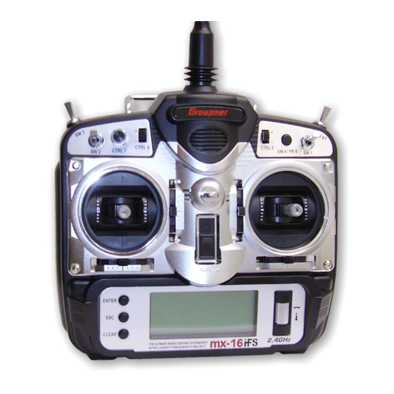
Page 14: Description Of Transmitter
Description of transmitter Transmitter controls Attaching the transmitter neckstrap You will fi nd a strap lug mounted in the centre of the Aerial with folding / swivelling joint front face of the -16iFS transmitter, as shown in the Neckstrap lug drawing on the right. - Page 15 For your notes...
-
Page 16: Dsc (Direct Servo Control)
Transmitter back panel Direct Servo Control The original function of this socket was for “Direct Servo Case screw Case screw Case screw Case screw Control”, and that’s why the abbreviation is still in use. However, for technical reasons “direct servo control” is no longer possible with iFS systems using the diagnosis lead. - Page 17 fi nd that it is necessary to swap over certain contacts at the battery plug or the DSC module. This work must be carried out by a GRAUPNER Service Centre. Description of transmitter: back panel...
-
Page 18: Lcd Screen
LCD screen and operating buttons Visual display of trim lever positions; alternatively – if the Error in Trainer mode Throttle stick danger- Operating voltage ously high inadequate rotary cylinder is held pressed in – display of the current settings of the two INC / DEC buttons (CTRL 5 + 6). throttl e ba tter y student... -
Page 19: Buttons, Function Fi Elds
Controlling the “Data Terminal” Input buttons and basic method of using the rotary cylinder Function fi elds ENTER, ESC, CLEAR SEL, STO, CLR, SYM, ASY, Buttons to the left of the screen brief press on the rotary cylinder at the top Function fi... -
Page 20: Adjusting Screen Contrast
Adjusting screen contrast Position display Servo display INC / DEC button, CTRL 5 + 6 The contrast of the -16iFS transmitter’s LCD screen Holding the rotary cylinder pressed in while you are at Pressing the rotary cylinder at the transmitter’s basic is variable, to ensure that you can read the information the transmitter’s basic display calls up a visual display of display calls up a visual representation of the current... - Page 21 … and for model helicopters: Bar 1 = Collective pitch or roll (2) or pitch-axis (2) servo Bar 2 = Roll (1) servo Bar 3 = Pitch-axis (1) servo Bar 4 = Tail rotor servo (gyro) Bar 5 = Pitch axis (2) servo / free channel Bar 6 = Throttle servo / speed controller Bar 7 = Gyro gain / free channel Bar 8 = Speed governor / free channel...
-
Page 22: Using The Transmitter For The Fi Rst Time
During this procedure taneous use of up to 120 models, although in practice the Graupner | iFS RF module (on the back of the trans- any Graupner | iFS receiver which has already been the mixed operation of different technical systems in mitter) briefl... - Page 23 fi ve seconds. FCC adaptive* / constant • The Status LED of Graupner | iFS receivers glows To change the output power, press the programming (USA, twelve channels) green in normal use if the output power is set to a button briefl...
-
Page 24: Using The Receiver For The Fi Rst Time
Using the receiving system for the fi rst time Preliminary notes, programming the XR-16ifs receiver (See also the instructions supplied with your particular receiver. For more information please visit the Internet site at www.graupner-ifs-system.de) Receiving system completely different locations from the model, e. g. as “Binding”... - Page 25 Graupner | iFS receiver on. After a few seconds the Sta- • After switching the model off at the end of a fl ight, Walk to a distance of at least 125 feet / 40 meters. If tus LED starts fl ashing red. Press and hold the program-...
-
Page 26: Expanded Receiver Programming Mode
Servo sockets and polarity (1), withdraw the red wire (2) and insulate the bare The servo sockets of the Graupner | iFS receiver are contact with tape to avoid numbered. The socket marked “B/T” is intended for possible short circuits (3). - Page 27 6 Telemetry set-up* ment by fl ashing green, you have a period of fi ve sec- a Graupner | iFS RF module to which the associated onds to enter a new assignment; this is accomplished by Graupner | iFS receiver has already been “bound”, Telemetry applications not currently available..
- Page 28 27 – press and hold a value which is higher than the permissible range, then helicopters in the case of most Graupner/JR systems), the programming button until the LED goes out. The the LED fl ashes alternately red and green (error indica- and assign the second or subsequent servos to one LED then fl...
- Page 29 If you do not press the programming button within the the number of fl ashes corresponding to the number of a period of about eight seconds. fi ve-second period, or if you enter an invalid number, seconds selected. For example, if the default value (2) is Within this time you should move the sticks and other then the LED fl...
-
Page 30: Installation Notes
Regardless of which Graupner | iFS receiver you are model: The sequence in which the servos are connected to the using, the procedure is always the same: Wrap the receiver in foam rubber at least 6 mm thick. - Page 31 For your notes...
-
Page 32: Defi Nition Of Terms
Defi nition of terms Control functions, transmitter controls, function inputs, control channels, mixers, switches, control switches To make it easier for you to understand the -16iFS • The INC / DEC buttons (CTRL 5 + 6) located on either the numerous mixer functions as described in the section manual, the following section contains defi... -
Page 33: Assigning Switches And Transmitter Controls
Assigning switches and control switches The basic procedure At many points in the program there is the option of using available in the “Helicopter” model type. This com- transmitter. a switch (SW 1 … 4, SW 6/7, PB 8) or a control switch pletes the assignment process. -
Page 34: Digital Trims
Digital trims Description of function, and Ch 1 cut-off trim Digital trims with visual and audible indicators 1. Fixed-wing models 2. Model helicopters The Ch 1 trim features a special cut-off trim which is In helicopter mode the Ch 1 trim has another feature in Both the dual-axis stick units are fi... - Page 35 For your notes...
-
Page 36: Fixed-Wing Model Aircraft
Fixed-wing model aircraft This program provides convenient support for normal elevator and rudder control functions in such a way that modes of control. model aircraft with up to two aileron servos and two fl ap each tail panel can be actuated by a separate servo. Depending on the model type you have selected, the servos, V-tail models, fl... -
Page 37: Receiver Socket Assignment
If you are using a GRAUPNER transmitter to control a model which was formerly fl own using a different make of transmitter fi tted with a Graupner | iFS RF module, 4 = Rudder / right V-tail e. g. when using the... - Page 38 Receiver socket assignment for models of the “Delta / Flying wing” type, with up to two fl aps As there are several possible combinations of servo orientation and control surface linkage, you may fi nd that the direction of rotation of one or more servos is incor- rect.
- Page 39 For your notes...
-
Page 40: Model Helicopters
Model helicopters The continued development of model helicopters and You can return to the correct idle position for the digital ner, who will initially simply set the hover point to coin- helicopter components, such as gyros, speed governors, Ch 1 trim simply by pressing a button. cide with the centre point of the stick arc, and adjust the rotor blades etc., has led to the current position where collective pitch travel as required. -
Page 41: Receiver Socket Assignment
If you are using a GRAUPNER transmitter to control a model which was formerly fl own using a different make 4 = Tail rotor servo (gyro) of transmitter fi tted with a Graupner | iFS RF module, e. g. when using the -16iFS for Trainer mode op-... -
Page 42: Reserving A New Memory
Detailed description of programming Reserving a new memory If you have already read through the manual to this Sel mo del type => select model point, you will undoubtedly have made your fi rst attempt => ( empty mod mem ) clear model at programming the system already. - Page 43 However, if you erase a model memory which is not you switching model memories in the interests of You will fi nd a description of the basic steps for program- currently active, after the procedure you will see the safety. In this case the screen displays this message: ming a fi...
-
Page 44: Model Memories
Model memories Calling up a model, erasing a model, copying model model The section on pages 18 and 19 explains the basic Select model Clear model method of using the buttons, while the previous double Hold the rotary cylinder pressed in and select the “clear =>... - Page 45 Caution: Copy model model model The erasure process is irrevocable. All model memo- Hold the rotary cylinder pressed in, select the “Copy ULTIMATE ry data is reset to the factory default settings. model model” sub-menu, and press ENTER or the empty rotary cylinder: t o be co pied ?
-
Page 46: Basic Settings« (Model)
Basic settings Basic model-specifi c settings for fi xed-wing model aircraft Before you start programming specifi c parameters, You can move to any character position within the input model name GRAUBELE some basic settings must be entered which apply only fi... - Page 47 too high” is activated (see page 18). In of the screen. Press the ENTER button or the rotary Ailerons / Camber-changing fl aps the »wing mixer« menu the “Brake cylinder: the current setting is highlighted. Now use the stick mode N.N.*”...
- Page 48 Timers Switching between “count-up” and “count-down” GRAUBELE stop 10:01 Two timers are shown in the basic display: one stop- Count-up timer (stopwatch function) 0:00 watch and one fl ight timer. If you assign a switch and start the stopwatch with the 9.6V «normal »...
- Page 49 Phase 2 / Phase 3 For more information on Trainer systems please refer to default sequence. page 122. Please note that any subsequent changes to servo clock 10:01 settings, such as servo travel, Dual Rate / Expo, mixers Receiver output phase 2 takeoff etc., must be carried out according to the original...
-
Page 50: Model Helicopter
Basic settings Basic model-specifi c settings for model helicopters Before you start programming specifi c parameters, You can move to any character position within the input model name STARLET some basic settings must be entered which apply only fi eld using the rotary cylinder pressed in; it is indicated stick mode to the currently active model memory. - Page 51 type. This is because model helicopters Swashplate type: 1 servo Direction of rotation of main rotor with only one collective pitch servo are model name STARLET controlled without transmitter mixers for stick mode the swashplate functions collective pitch, swashplate 3sv(2roll) pitch-axis and roll.
- Page 52 (Collective) pitch min Note: watch is halted (switched off). It can only be stopped by pressing with the stopwatch halted. • The Ch 1 trim always affects the throttle servo only. stick mode Once stopped, pressing CLEAR resets both timers to •...
- Page 53 that the stopwatch switches to the “Timer” function; see Phase 2 Trainer / student top right in the next illustration. rotor direct left clock 10:01 STARLET 10:01 stop pitch min front phase 2 hover clock 10:01 autorotat. 0:00 phase 2 hover train.
- Page 54 GRAUPNER/JR mc-systems. The throttle servo is now assigned to receiver output “6” and the collective pitch servo to output “1”. You may therefore wish to retain the earlier confi...
- Page 55 For your notes...
-
Page 56: Servo Settings
Servo settings Servo direction, centre, travel Column 2 “rev” Column 3 “cent” 100% 100% The direction of servo rotation can be adjusted to suit The facility to offset the servo travel centre is intended 100% 100% the actual installation in your model. This means that for adjusting servos whose centre setting is not standard 100% 100% you don’t need to concern yourself with servo directions... - Page 57 Column 4 “- trav +” In this column you can adjust servo travel symmetrically or asymmetrically (different each side of neutral). The adjustment range is 0 … 150% of normal servo travel. The reference point for the set values is the setting in the “Centre”...
-
Page 58: Transmitter Control Settings
Transmitter control settings Basic procedures for assigning transmitter controls and switches the “supplementary” transmitter controls for any task set the desired value using the rotary cylinder. emp ty + 100% 100% you like, and that you are not required deliberately to Press the rotary cylinder to conclude the input proc- emp ty 100%... - Page 59 Tips: Column 3 “- trv +” inputs, i. e. all servos which are affected by that transmit- ter control. • When assigning the switches please take care to set Hold the rotary cylinder pressed in to select one of the them to the appropriate direction of travel, and en- inputs 5 to 8.
-
Page 60: Model Helicopter
Transmitter control settings Basic procedures for assigning transmitter controls and switches the “supplementary” transmitter controls for any task to make. emp ty + 100% 100% you like, and that you are not required deliberately to Press the rotary cylinder: the input fi eld you want to emp ty 100% 100%... - Page 61 in addition to the two end-points. Column 3 “- trv +” inputs, i. e. all servos which are affected by that transmit- ter control. Pressing the CLEAR button with the switch assignment Hold the rotary cylinder pressed in to select one of the activated –...
-
Page 62: Throttle Limit Function
Throttle limit function “Lim” input “Throttle” „Gyro“ Meaning and application of “throttle limit” 100% 100% 100% 100% ctrl6 111% e mpty 100% 100% empty 100% 100% emp ty 100% 100% ctrl7 100% 100% ctr l6 111% ctrl6 111% tr v tr v tr v In principle all transmitter controls (rotary proportional... -
Page 63: Basic Idle Setting
curve, and therefore reach its full-throttle setting, if you Tip: »servo set.« menu. release full servo travel using the throttle limit control. You can call up the »Servo display« menu to check the Now close the throttle limiter completely by turning the That is why the “Lim”... - Page 64 collective pitch stick to and fro slightly at the minimum end-point. When you do this, the throttle servo must not Throttle limit contro stop move! In any case fi ne-tuning must be carried out with f lt the model fl ying. «norm The motor is always started with the throttle limiter completely closed;...
- Page 65 For your notes...
-
Page 66: Fixed-Wing Model Aircraft
Dual Rate / Expo Switchable control characteristics for aileron, elevator and rudder rate of travel of the control surface declines steadily Dual Rate function aile 100% towards the extremes, dependent upon the position of If you wish to switch between two possible D/R settings, elev 100% the linkage point on the output disc or lever. - Page 67 Exponential function Combined Dual Rate and Expo If you wish to switch between two settings, select the If you enter values for both Dual Rates and Expo, the fi eld and assign a switch as described on page 33. two functions are superimposed as follows: The assigned switch appears in the screen together with Expo = +100%, DR = 125% Expo = +100%, DR = 50%...
-
Page 68: Model Helicopter
Dual Rate / Expo Switchable control characteristics for roll, pitch-axis and tail rotor linearity of rotary-output servos, which are the standard Dual Rate function roll 100% nowadays. With a rotary servo the movement of the If you wish to switch between two possible D/R settings, nick 100% control surface is inevitably non-linear, as the linear... - Page 69 Exponential function Combined Dual Rate and Expo If you wish to switch between two settings, select the If you enter values for both Dual Rates and Expo, the fi eld and assign a switch as described on page 33. two functions are superimposed as follows: The assigned switch appears in the screen together with Expo = +100%, DR = 125% Expo = +100%, DR = 50%...
-
Page 70: Phase Trim« (Fi Xed-Wing Model Aircraft)
Phase trim Flight phase-specifi c trims for fl aps, ailerons and elevator If you have not assigned a switch to “Phase 2” and / when thermalling, or faster when fl ying speed tasks, but clock 0:00 or “Phase 3” in the »base sett.« menu, i. e. you have WITHOUT having to change the basic settings each phase 2 takeoff... - Page 71 P H A S E T R I M normal takeoff – 7% – – speed FLAP AILE ELEV Note: When setting up »phase trim«, only the column “ELEV”, the columns “AILE” and “ELEV”, or – as shown above – “FLAP”, “AILE”...
-
Page 72: What Is A Mixer
What is a mixer? Fixed-wing mixers The basic function In many models it is often desirable to use a mixer to Notes: d i f f a i l e . couple various control systems, e. g. to link the ailerons •... - Page 73 nates the danger of errors when a fl ap command is at which the airbrakes are always retracted, is the given. forward position of the Ch 1 stick (throttle / airbrakes) if you select “no” in the “Motor at Ch 1” line of the »base The basic programming procedure sett.«...
- Page 74 fl yers, when ailerons alone are often used for turning the rudd (Aileron rudder) into the fl ap channel. When an aileron command is model. given, the fl aps “follow” the ailerons, although usually through a smaller angle, i. e. the mixer ratio is gener- Pressing CLEAR resets the value to 0%.
- Page 75 fi gures. It is essential to check and adjust this setting at to +150%. Note: a safe height. If your model features full-span (strip) ailerons which Pressing CLEAR resets the value to 0%. also double as camber-changing fl aps, the two mix- It can also be useful to defl...
- Page 76 elev aile (Elevator aileron) fl ap aile (Flap aileron) differential when you invoke the butterfl y setting using the airbrake stick. Differential is reduced progressively, or even eliminated altogether, as the airbrake stick is moved towards its end-point. A value of 0% at this point means that the full pro- grammed aileron differential is retained.
- Page 77 For your notes...
-
Page 78: Helicopter Mixers
Helicopter mixers Flight phase-specifi c mixers for collective pitch, throttle and tail rotor In the »base sett.« menu a method of switching fl ight Description of the helicopter mixers ptch phases can be activated by assigning the appropriate Five-point curves are available for setting up the control thro switches to “Phase 2”... - Page 79 The programming procedure in detail +75%. characteristics by no means represent real collective pitch curves! Start by switching to the desired fl ight phase, e. g. However, points “2” and “4” can optionally be activated, “normal”. even though they are disabled by default: ptch The throttle / collective pitch stick can now be used to ptch...
- Page 80 thro (Throttle curve) started and stopped using the throttle limiter (see Notes on using the “Throttle limit” function: below). • We strongly recommend that you make use of the thro If you are used to a different radio control system which throttle limit function (»contr set.«...
- Page 81 When you select auto-rotation, the mixer automati- tle”) output value. The “height” of the line in the graph render your helicopter completely uncontrollable. cally switches the value to a variable pre-set value; determines the nominal system rotational speed. If you use your gyro sensor in “normal” operating mode, see the section starting on page 86.
- Page 82 gyro (adjusting gyro gain) full travel (away from centre), the gyro gain increases ing effect may be an over-reaction which manifests itself accordingly … as tail oscillation. In order to obtain optimum stabilisation Most modern gyro systems feature proportional, infi nite- from a gyro in all fl...
-
Page 83: Adjusting The Throttle And Collective Pitch Curves
Adjusting the throttle and collective pitch curves A practical procedure Although the throttle and collective pitch control systems Idle setting and throttle curve has to be adjusted in the hover range. are based on separate servos, they are always operated The basic set-up procedure Note: in parallel by the throttle / collective pitch stick (except... - Page 84 With the basic set-up completed, it should be possible to 2. The model lifts off below the centre point. The climb setting start the motor in accordance with the operating instruc- a) Rotational speed too high The combination of throttle hover setting, collective pitch +100% tions supplied with it, and adjust the idle setting using Remedy: reduce the throt-...
- Page 85 Conversely, if the model hovers below the mid-point, This completes the set-up procedure for throttle and This causes the rotor to accelerate quickly, resulting in correct this by reducing the pitch angle again. collective pitch. premature wear of the clutch and gear train. The main rotor blades are generally free to swivel, and they may You may fi...
-
Page 86: Auto-Rotation Settings
Helicopter mixers Auto-rotation settings Auto-rotation allows full-size and model helicopters to facilities which are designed to help you fl y your helicop- speed into a descent of around 60 … 70° when collec- land safely in a crisis, i. e. if the power plant should fail. ter in its unpowered state. - Page 87 rotation; for an electric helicopter the motor should be slight torque which causes this effect must then be reliably “off”. corrected by adjusting the tail rotor blade pitch angle. This value will always be a small fi gure between zero tail (static torque compensation) degrees and a pitch angle opposed to the direction of...
-
Page 88: General Notes Regarding Freely Programmable Mixers
General notes regarding freely programmable mixers The two menus »wing mixer« and »heli mixer«, as to assign an optional ON / OFF switch to it. However, described on the preceding pages, contain a wide range since there are so many functions to which switches can of ready-programmed coupling functions. -
Page 89: Free Mixers
Free mixers Linear mixers Regardless of the selected model type, three linear mix- “fro(m)” column “to” column. ers are available for each of the twelve model memories, Press the rotary cylinder, then rotate it to select one of At this point you can defi ne the control channel as the with the additional possibility of non-linear characteristic the control functions 1 …... - Page 90 “Typ(e)” column (including the trim) »servo set.« menu, and / or reduce the mixer values. Mixer Effect If you wish, and if you are using one of the primary con- N.N.* Servo pair 2 + 5 responds with aileron Mixer ratios and mixer neutral point trol functions 1 …...
- Page 91 »contr set.« menu control travel at which the mixer has NO infl uence on the MIX 1 channel connected to its output. By default this point is emp ty 100% 100% set to the centre position. 100% 100% ct r l7 However, in our example the neutral (retracted) position e mp ty 100%...
-
Page 92: Examples
Symmetrical mixer ratios achieve this effect. The vertical line then jumps between MIX 1 the left and right sides. The next step is to defi ne the mixer values above and + 20% + 20% tr v below the mixer neutral point, starting from the cur- Examples: offs 100%... -
Page 93: Swashplate Mixers
Swashplate mixers Collective pitch, roll and pitch-axis mixers • collective pitch mixer acts on the two collective MIX 3 – M I X E R pitch servos connected to receiver sockets 1 + 2; p tch tr v • roll mixer also acts on the two collective pitch ro ll offs 100%... -
Page 94: Introduction
-16iFS programming techniques Preparation, using a fi xed-wing model aircraft as an example Programming model data into an -16iFS … for poor-quality construction and defective installation by the down-movement of the fl aps rather than the methods. up-movement of the ailerons, so in this case the servo …... - Page 95 and you gain experience, you might feel the need to try “throttle min. front / rear” is the effect of the Ch 1 trim. glider is on the landing approach. It surely makes more out different control systems and other refi nements, and The trim is effective over the full stick travel if “no (/ inv)”...
-
Page 96: First Steps In Programming A New Model
First steps in programming a new model Example: non-powered fi xed-wing model aircraft When programming a new model you should start with erasing the model memory. 18 or 46 … 47 – is disabled. the ... • If the battery voltage is too low, you will not be able •... - Page 97 “direction of rotation”, “neutral set- elev aile GRAUPNER sequence: ting” and “servo travel”, to suit the requirements of the flap elev model. aile flap Auxiliary function By “requirements”...
- Page 98 tween 20% and 40% is usually a good starting point, but … and if you wish to be able to defl ect both ailerons up mixer at 0%. the “perfect” setting nearly always has to be established using the throttle / brake stick (Ch 1), then a suitable The “fl...
- Page 99 »D/R Expo« (page 66) aile 111% elev 111% rudd 100% DUAL EXPO ... in order to adjust the overall set-up to suit your requirements and fl ying style. Dual Rates are used to adjust the magnitude of the stick’s effect (see page 66). However, if it is only the model’s control response around neutral which is too powerful for comfortable fl...
-
Page 100: Including An Electric Power System
Expanded programming: including an electric power system Example 1 »servo set.« menu. (page 56) Using the rotary proportional control CTRL 7 100% 100% If this transmitter control is used, the set-up is extremely 100% 100% easy. All you have to do is connect the speed control- 100% 100% ler to any of the receiver servo sockets 5 …... - Page 101 assigned two aileron servos in the »base sett.« menu, Example 3 »servo set.« menu. (page 56) and if you have not connected any other auxiliary func- Using the three-position switch SW 6/7 100% 100% tion, then this would be channel 6; if your model features This variant implements a three-stage solution for 100% 100% two aileron servos and two fl...
-
Page 102: Electric Motor And Butterfl Y (Crow) With The Ch 1 Stick
Controlling the electric motor and butterfl y (crow) system using the Ch 1 stick (Butterfl y / crow system as landing aid: ailerons up, fl aps down) Example 4 the other settings can be adopted as described. before you continue with the programming procedure. Before we start the programming of this fourth example, In the …... - Page 103 … menu where you need to program a free mixer “c1 »Servo display« (page 20) cylinder briefl y, then assign your selected “change-over c1”. When you have done this, move to the (switch) switch” by moving your preferred switch from “forward” –...
- Page 104 104 For your notes...
-
Page 105: Operating The Timers
Operating the timers using the Ch 1 stick or a switch SW 1 … 7 If, following on from the model programming described timer by pressing ESC, and then reset both timers to the same switch to the “clocks”, with the same switching on the preceding pages, you have decided on Example their starting value by pressing CLEAR... -
Page 106: Using Fl Ight Phases
Using fl ight phases Within any of the twelve model memories you can Each of the two end-points of this switch should be position, and enter the desired values in the standard program up to three different fl ight phases (states of assigned to one fl... -
Page 107: Servos Running In Parallel
… menu and set up a mixer “tr rd 8”. In the “Type” (Order No. 3162 – available in the Graupner range) in- column select the “tr” setting, so that the rudder trim stead of a simple Y-lead. This unit allows one transmitter affects both rudder servos. -
Page 108: Model Deltas And Fl Ying Wings
Programming example: Delta / fl ying wing • “no/inv”: On page 94, where the section on fi xed-wing model Auxiliary function programming starts, you will fi nd general notes regard- Right flap The brake system is “retracted” at Left flap ing installing and setting up the RC system in a model, the “back”... - Page 109 »wing mixer« (pages 72 … 76) same direction and provide an elevator effect when an digital trim of the elevator stick – so an alternative has to elevator command is given. The procedure starts by be found. d i f f a i l e .
- Page 110 effect, in the »Servo display«, or on the model itself, ment you have selected. This is because differential and change the prefi xes if necessary. travels tend to produce an asymmetrical elevator effect on a tailless model, rather than the desired adverse yaw If you carry out the programming as described above, reduction.
- Page 111 For your notes...
-
Page 112: F3A Models
Programming example: F3A model aircraft F3A models belong to the category of powered fi xed- fi xed-wing models we have already described. »servo set.« (page 56) wing model aircraft designed for competition fl ying. They The auxiliary function “Retracts” is usually assigned to 100% 100% may be powered by an internal combustion engine or an one of the auxiliary channels 6 to 8. - Page 113 You may fi nd it necessary to assign transmitter controls the typical F3A model. Many experts use higher values; to particular inputs to operate the retractable undercar- even up to +60% exponential. riage and carburettor mixture adjustment. This is carried aile 100% out in the...
- Page 114 the mixers of a computer radio control system are then b) Correction around the longitudinal axis (aileron) centre position, and set up the mixer ASYmetrically. required to compensate for these defi ciencies. In this MIX “rd ar” Rolling when ailerons and fl aps are extended section we will describe how to carry out the adjust- ASYmmetrical setting.
- Page 115 function takes effect. Summary The settings described on this page are intended prima- rily for the expert fl yer. Please bear in mind that refi ning the fl ying characteristics of a model to this extent in- volves tremendous effort, time, sensitivity and expertise. Some experts continue the programming procedure even when they are fl...
-
Page 116: Model Helicopters
As our programming example we take the GRAUPNER STARLET 50 helicopter, with right-hand rotation, three After a brief press of the rotary cylinder or pressing The memory should now be assigned an appropriate swashplate linkage points distributed evenly at 120°... - Page 117 In the “(Collective) pitch min.” line set “front” collective pitch servo and the throttle servo have been stick mode or “rear” to suit your personal preference. This set- interchanged in later GRAUPNER radio swashplate 1 servo ting applies equally to all subsequent mixers, and it is control systems.
- Page 118 the rotary proportional control CTRL 7, is assigned to restrict the full throttle travel dictated by the collective Note: the “lim” input, whereas all other inputs are programmed pitch stick when the model is in fl ight. For more information on setting up this “emergency OFF to “empty”...
- Page 119 +50%. of around 65%. tail Note: thro gyro A rotor blade set-up gauge, e. g. the GRAUPNER item, input 100% Autorot Order No. 61, is very useful when setting up blade pitch output...
- Page 120 should be changed to a value which provides a reliable now be altered by setting a value other than “0” in the Additional notes on setting up gyros can be found on idle. “Gyro” line: page 81. Set-up note for electric helicopters: Further adjustments ptch Since the motor must be stopped completely if an emer-...
- Page 121 other menu settings which you entered separately for ter is to install and program the speed governor exactly each fl ight phase (see page 78). in accordance with the manufacturer’s instructions. Of course, the -16iFS provides further facilities to For example, if the motor run is limited by the fueltank allow you to implement different rotational speeds in the size or battery capacity, you should set the stopwatch individual fl...
-
Page 122: Mx -16Ifs
Trainer system Total control transfer -16iFS as Pupil transmitter the “classic” 35 / 40 MHz band; see right-hand picture GRAUBELE stop 0:00 on the next double page. For example, an -16iFS The model to be controlled by the pupil MUST be pro- 0:00 Teacher transmitter can also be connected to an grammed completely in a model memory of the Teacher... - Page 123 Checking the functions Operate the assigned Trainer change-over switch: • The Pupil system is working properly if no error message appears in the basic display of the Teacher transmitter when you operate the assigned change- over switch. • However, if the basic display shows the message s tu d e n t s ig n a l then there is a problem with the connection;...
-
Page 124: Appendix
Appendix Trainer mode operations with the -16iFS transmitter Due to the steadily growing product range please refer to www.graupner.com for the latest information. -16iFS Pupil transmitter nsmitter -16iFS Teacher transmitter ransmitter Trainer lead, Trainer lead, Trainer lead, Trainer lead, Order No. 4179.1 Order No. - Page 125 This unit guarantees a stabilised, user-variable power supply for the program the settings of Graupner | iFS RF modules or Graupner | iFS receiver, with the aim of further enhancing the reliability of the power A selector switch is used to select each of the connected servos receivers wirelessly, and also to update the fi...
-
Page 126: Approved Transmitter Output Stages And National Receiver Settings
Approved transmitter output stages and national receiver settings In order to fulfi l various directives including FCC, ETSI, IC etc., and other statutory regulations valid in individual countries, this radio control system is only approved for use with the transmitter output stages and national receiver settings stated below. Please observe the legal restrictions which apply to you. It is prohibited to use the radio control system with settings other than those stated below. -
Page 127: Conformity Declaration
Conformity declaration Conformity declaration... - Page 128 128 For your notes...
- Page 129 For your notes 129...
- Page 130 130 For your notes...
-
Page 131: Guarantee Certifi Cate
Guarantee certifi cate Sur ce produit nous accordons une garantie de mois Servicestellen / Service / Service après-vente Die Fa. Graupner GmbH & Co. KG, Henriettenstraße 94-96, 73230 Kirchheim/Teck gewährt ab dem Kaufdatum Graupner-Zentralservice Servicehotline auf dieses Produkt eine Garantie von 24 Monaten. Die Graupner GmbH &... - Page 132 However, we accept no liability of any kind for errors, omissions and printing D-73220 KIRCHHEIM/TECK We will gladly supply addresses of retailers. errors. GRAUPNER reserves the right to modify the software and hardware features GERMANY described in this manual at any time and without prior notifi cation.
Need help?
Do you have a question about the mx-16 ifs and is the answer not in the manual?
Questions and answers